1
R
Room Air Conditioner
INSTALLATION AND OPERATING INSTRUCTIONS
Models:
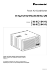
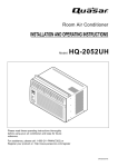
CW-XC65HU, CW-XC85HU
Please read these operating instructions thoroughly
before using your air conditioner and keep for future reference.
For U.S customers :
For assistance, please call : 1-800-211-PANA(7262) or
Register your product at : http://www.panasonic.com/register
CW382820391N
Safety Precautions
Safety Precautions
Safety Precautions .............3
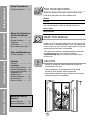
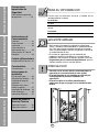
FOR YOUR RECORDS
Staple your receipt to this page in case you need it later.
Write down the model and serial numbers here:
Model #
Serial #
You can find them on a label on the side of each unit.
Dealer's Name
Before you call for service...
Features and Installation
About the Controls on the Air Conditioner
Date Purchased
About the Controls on
the Air Conditioner
Controls..............................5
Remote Controller ..............6
Ventilation ..........................7
Air Direction........................7
How to Secure Drain Pipe ....7
Care and Maintenance
Air Filter Cleaning...............8
Features
Features .............................9
Installation
How to Install the Unit ......10
Window Requirements .....10
Installation Kit Contents ...11
Suggested Tool
Requirements...................11
Cabinet Installation...........12
Electrical Data ..................14
Electrical Safety ...............15
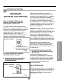
READ THIS MANUAL
Inside you will find many helpful hints on how to use and
maintain your air conditioner properly. Just a little preventive
care on your part can save you a great deal of time and
money over the life of your air conditioner.
You'll find many answers to common problems in the chart
of troubleshooting tips. If you review our chart of
Troubleshooting Tips first, you may not need to call for
service at all.
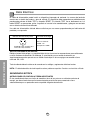
CAUTION
• Contact an authorized Service technician for repair or
maintenance of this unit.
• The air conditioner is not intended for use by young
children or infirm persons without supervision.
• Young children should be supervised to ensure that they
do not play with the air conditioner.
Before you call for
service...
Normal Operation.............16
Abnormal Operation .........16
2
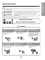
To prevent injury to the user or other people and property damage, the following instructions must be
followed.
■ Incorrect operation due to ignoring of instruction will cause harm or damage. The seriousness is classified
by the following indications.
WARNING
: This symbol indicates the possibility of death or serious injury.
CAUTION
symbol indicates the possibility of injury or damage to
: This
property only.
■ Meanings of symbols used in this manual are as shown below.
Be sure not to do this.
Be sure to follow the instructions.
WARNING
Plug in the power plug
properly.
Do not operate or stop the
unit by inserting or pulling
out the power plug.
Do not damage or use an
unspecified power cord.
• Otherwise, it will cause electric
shock or fire due to heat
generation.
• It will cause electric shock or fire
due to heat generation.
• It will cause electric shock or fire.
• If the power cord is damaged, it must
be replaced by the manufacturer or
an authorized service center or a
similarly qualified person in order to
avoid a hazard.
Do not modify power cord
length or share the outlet
with other appliances.
Do not operate with wet
hands or in a damp
environment.
Do not direct air flow at room
occupants.
• It will cause electric shock or fire
due to heat generation.
• It will cause electric shock.
• This could lead to health
problems.
3
Safety Precautions
Safety Precautions
Safety Precautions
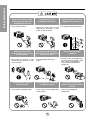
When the air filter is to be
removed, do not touch the
metal parts of the unit.
• It may cause an injury.
When the unit is to be
cleaned, switch off, and turn
off the breaker.
• Since the fan rotates at high
speed during operation, it may
cause an injury.
Do not operate switches
with wet hands.
• It may cause an electric shock.
Do not clean the air
conditioner with water.
• Water may enter the unit and
degrade the insulation. It may
cause an electric shock.
Do not put a pet or house
plant where it will be exposed
to direct air flow.
• This could injure the pets or
plants.
Do not apply an insecticide
or flammable spray.
• It may cause a fire or deformation
of the cabinet.
4
Ventilate well when used
together with a stove, etc.
• An oxygen shortage may occur.
Do not use for special
purposes.
• Do not use this air conditioner to
preserve precision devices, food,
pets, plants, and art objects.
It may cause deterioration of
quality, etc.
Do not put a heater, etc.
where it is exposed to direct
air flow.
• It may cause imperfect
combustion.
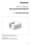
About the Controls on the Air Conditioner
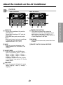
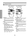
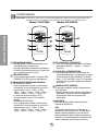
Controls
Model: CW-XC85HU
Model: CW-XC65HU
7
F
4
FAN
SPEED
TIMER
TIMER
FAN COOL
DRY
MODE
2
6
OFF/ON
1
ECONOMY
FAN COOL
AIR
SWING
DRY
TIMER
OFF/ON
MODE
OPERATION
TEMP
3
AIR
SWING
3
5
2
1
OPERATION
TEMP
5
OPERATION
• To turn the air conditioner ON, push the
OFF/ON button.
To turn the air conditioner OFF, push the
button again.
• This button takes priority over any other
buttons.
• When you first turn it on, the air conditioner
is on the High cool mode and the
temperature is set at 72°F (22°C)
TEMPERATURE SETTING
• This button can automatically control the
temperature of the room. The temperature can
be set within a range of 60°F to 86°F by 1°F
(16˚C to 30˚C by 1˚C) Select a lower number for
a lower temperature in the room.
MODE
• Every time you push this button, it will
toggle between COOL,ECONOMY, FAN
and DRY.
REMOTE CONTROL SIGNAL RECEIVER
AIR SWING
• This button can automatically control the air flow
direction.
ON/OFF TIMER
• Every time you push the TIMER button,
timer is set as follows. (1Hour → 2Hours →
3Hours → 4Hours → 5Hours → 6Hours →
7Hours → 8Hours → 9Hours → 10Hours →
11Hours → 12Hours → O)
• The Setting Temperature will be raised by
2°F(1˚C) 30 min. later and by 2°F(1˚C) after
another 30 min.
FAN SPEED
• Every time you push this button it is set as
follows. {High(F3) → Low(F1) → Med(F2) →
High(F3)...}.
5
About the Controls on the Air Conditioner
TIMER
FAN
SPEED
4
ECONOMY
7
F
hr
hr
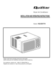
Remote controller
Precaution: The Remote Controller will not function properly if strong light strikes the sensor window of the
air conditioner or if there are obstacles between the Remote Controller and the air conditioner.
Model: CW-XC85HU
Model: CW-XC65HU
OPERATION
OPERATION
1
1
About the Controls on the Air Conditioner
TEMP
TIMER
3
TEMP
AIR
SWING
5
7
MODE
FAN SPEED
2
5
TIMER
3
MODE
4
2
FAN SPEED
4
ECONOMY
ECONOMY
6
6
OPERATION
• To turn the air conditioner ON, push the button.
To turn the air conditioner OFF, push the button
again.
• This button takes priority over any other buttons.
• When you first turn it on, the air conditioner is on
the High cool mode and the temp. at 72°F (22˚C).
MODE
• Every time you push this button,it will toggle
between COOL, ECONOMY, FAN and DRY.
FAN SPEED
• Every time you push this button it is set as follows.
{High(F3) → Low(F1) → Med(F2) → High(F3)...}.
TEMPERATURE SETTING
• This button can automatically control the
temperature of the room.
The temperature can be set within a range of 60°F
to 86°F by 2°F.(16˚C to 30˚C by 1˚C) Select the
lower number for lower temperature of the room.
ECONOMY
• If the switch is set to "On", the fan stops when the
compressor stops cooling. Approximately every 3
minutes the fan will turn on and check the room air
to determine if cooling is needed.
ON/OFF TIMER
- STOPPING OPERATION
• Every time you push this button, when the air
conditioner is operating, timer is set as follows.
(1Hour → 2Hours → 3Hours → 4Hours → 5Hours
→ 6Hours → 7Hours → 8Hours → 9Hours →
10Hours → 11Hours → 12Hours → O)
• The Setting Temperature will be raised by
2°F (1°C) 30 min. later and by 2°F (1°C) after
another 30 min.
- STARTING OPERATION
• Every time you push this button, when the air
conditioner is not operating, timer is set as follows.
(1Hour → 2Hours → 3Hours → 4Hours → 5Hours
→ 6Hours → 7Hours → 8Hours → 9Hours →
10Hours → 11Hours → 12Hours → O)
AIR SWING
• This button can automatically control the air flow
direction.
DRY
• When this unit is in dry mode, the fan rotates in
low speed. The fan stops when the compressor
stops cooling.
Approximately every 3 minutes the fan will turn on
and the unit checks the room air temperature to
set itself.
6
Additional controls and important information.
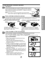
Ventilation
The ventilation lever must be in the CLOSE position in order to maintain the best
cooling conditions. When fresh air is necessary in the room, set the ventilation
lever to the OPEN position.
The damper is opened and room air is drawn out.
CLOSE
VENT
NOTE: Before using the ventilation feature, and prior to installing the front grille,
Part A
pull down part until level with part .
OPEN
Part B
The direction of air can be controlled wherever you want to cool by adjusting the horizontal
louver and the vertical louver.
• VERTICAL AIR-DIRECTION CONTROL • HORIZONTAL AIR-DIRECTION CONTROL
Controlled
manually
The vertical air direction is adjusted by
rotating the horizontal louver forward or
backward manually.
Controlled by Remote
Controller (Model: CW-XC85HU)
Controlled
manually
The horizontal air direction is adjusted by rotating
the vertical louver right or left manually or by
Remote Controller.
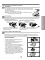
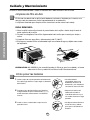
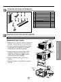
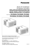
How to Secure the Drain Pipe
In humid weather, excess water may cause the BASE PAN to overflow. To drain the water, remove the
DRAIN CAP and secure the DRAIN PIPE to the rear hole of the BASE PAN. Press the drain pipe into the
hole by pushing down and away from the fins to avoid injury.(See Fig.1)
Optional(CW3H02502C)
1. Remove the rubber plug and slide the chassis out
from the cabinet.(See Fig. 2)
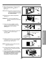
2. Install the drain pan over the corner of the cabinet
where you removed the plug with 4 (or 2)
screws.(See Fig. 3)
3. Connect the drain hose to the outlet located at the
bottom of the drain pan. You can purchase the drain
hose or tubing locally to satisfy your particular
needs. (Drain hose is not supplied).(See Fig. 3)
4. Select the most appropriate connection from among
the figures to the right (by considering the hole of the
unit) to fit drain pan to your own unit.(See Fig. 3)
5. Slide the chassis back into the cabinet. Reinstall the
cabinet screws. Secure the cabinet to chassis by
using screws. (See Fig. 4)
Drain pipe
Drain cap
Fig. 1
OPERATION
TIMER
SET
F
TE P/TI
OFF/ON
SET/E
C N
ECONOMY
AIR
COOL
MO
E
FAN
HIGH
MED FAN
rol
Wireless
Cont
Remote
SPEED
LOW
Remove the
rubber plug
Fig. 2
CABINET
DRAIN HOSE
Inside diameter 17mm (5/8")
DRAIN
PAN
SCREW
F
hr
TIMER
TEMP/TIMER
FAN
OPERATION
SET
SET/
CANCEL
COOL
Fig. 3
OFF/ON
MODE
AIR SWING
HIGH
MED
LOW
ECONOMY
FAN SPEED
Wireless
Remot
e Cont
r
ol
Fig. 4
7
About the Controls on the Air Conditioner
Air Direction
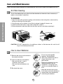
Care and Maintenance
TURN THE AIR CONDITIONER OFF AND REMOVE THE PLUG FROM THE POWER OUTLET.
Air Filter Cleaning
The air filter behind the front grille should be checked and cleaned at least once every 2
weeks or more often if necessary.
About the Controls on the Air Conditioner
TO REMOVE:
1. Open the inlet grille upward by pulling out the bottom of the inlet grille or downward by
pulling out the top of the inlet grille.
2. Using the tab, pull up slightly on the filter to release it and pull it down or up.
3. Clean the filter with warm, soapy water under 40°C (104°F).
4. Rinse and gently shake the water from the filter and let it dry before replacing it.
CAUTION: DO NOT operate the air conditioner without a filter because dirt and lint will
clog it and reduce performance.
How to Insert Batteries
1. Remove the cover from the back of
• Do not use rechargeable
batteries. Such batteries
differ from standard dry cells in
shape, dimensions, and
performance.
• Remove the batteries from the
remote controller if the air
conditioner is not going to be
used for an extended length of
time.
• Keep the remote control away
from infants and small children to
prevent them from accidentally
swallowing the batteries.
the remote controller.
2. Insert two AAA dry cell batteries.
• Be sure that the (+) and (-)
directions are correct.
• Be sure that both batteries are
new.
3. Re-attach the cover.
8
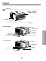
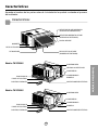
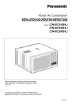
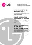
Features
Learning parts name prior to installation will help you understand the installation procedure.
Features
VERTICAL AIR DEFLECTOR
(HORIZONTAL LOUVER)
HORIZONTAL AIR DEFLECTOR
(VERTICAL LOUVER)
AIR DISCHARGE
CABINET
FRONT GRILLE
AIR FILTER
AIR INTAKE
(INLET GRILLE)
Model: CW-XC85HU
BRACE
VERTICAL LOUVER
COMPRESSOR
BASE PAN
F
FAN
SPEED
hr
TIMER
CONTROL BOARD
ECONO
MY
FAN
COOL
DRY
TIMER
AIR
SWING
MODE
OFF/O
N
POWER CORD
REMOTE CONTROLLER
Model: CW-XC65HU
BRACE
COMPRESSOR
CONDENSER
EVAPORATOR
BASE PAN
F
FAN
hr
SPEED
TIMER
CONTROL BOARD
ECONO
MY
TIMER
FAN
COOL
DRY
MODE
OFF/O
N
POWER CORD
REMOTE CONTROLLER
9
Features and Installation
CONDENSER
EVAPORATOR
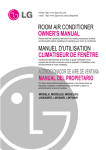
INSTALLATION
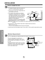
How to Install the Unit
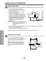
1. To prevent vibration and noise, make sure
the unit is installed securely and firmly
2. Install the unit where the sunlight does not
shine directly on the unit.
3. The outside of the cabinet must extend
outward for at least 28 cm (11") and there
should be no obstacles, such as a fence or
wall, within 50.8 cm (20") from the back of
the cabinet because it will prevent heat
radiation of the condenser.
Restriction of outside air will greatly reduce
the cooling efficiency of the air conditioner.
Fence
Awning
Cooled air
76.2 cm (30")~
152.4 cm (60")
Heat
radiation
About 12.7 mm (1/2")
Over 50.8 cm (20")
CAUTION: All side louvers of the cabinet must remain exposed to the outside of the
structure.
4. Install the unit a little slanted so the back is slightly lower than the front
(about 12.7 mm (1/2")).
This will force condensed water to flow to the outside.
Features and Installation
5. Install the unit with the bottom about 76.2 cm (30")~152.4 cm (60") above the floor level.
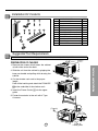
Window Requirements
NOTE: All supporting parts should be secured to firm wood, masonry, or metal.
This unit is designed for installation in
standard double hung windows with actual
opening widths from 55.88 cm (22") to 91.44
cm (36").
The top and bottom window sash must open
sufficiently to allow a clear vertical opening of
38 cm (15") from the bottom of the upper
sash to the window stool.
10
55.8 cm (22") to
91.44 cm (36")
38 cm (15") min Stool
(With frame curtain)
Offset
12.7 mm (1/2") to
31.8 mm (11/4")
Sill
Interior wall
47 cm (181/2") min.
(Without frame curtain)
Exterior
Installation Kit Contents
2
1
5
6
3
4
7
8
NO.
1
2
3
4
5
6
7
8
9
10
11
10
9
11
NAME OF PARTS
Q'TY
FRAME CURTAIN
2
SILL SUPPORT
2
BOLT
2
NUT
2
SCREW(TYPE A) (10mm (25/64")) 13
3
SCREW(TYPE B) D5.1mm(3/16")/16mm(5/8")
SCREW(TYPE C) D4.1mm(5/32")/16mm(5/8")
5
FOAM-STRIP
1
1
WINDOW LOCKING BRACKET
1
FOAM-PE (920mm x 30mm x 2mm)
DRAIN PIPE
1
Suggested Tool Requirements
SCREWDRIVER(+, -), RULER, KNIFE, HAMMER, PENCIL, LEVEL
Shipping
Screws
PREPARATION OF CHASSIS
Features and Installation
1. Remove the screws which fasten the cabinet
at both sides and at the back.
2. Slide the unit from the cabinet by gripping the
base pan handle and pulling while bracing the
cabinet.
3. Cut the window sash seal to the proper
length.
Peel off the backing and attach the FOAM-PE
to the underside of the window sash.
4. Insert the Frame Curtain
guide.
into the upper
5. Fasten the curtains to the unit with 4 Type
A screws.
10
(Type A)
5
5
11
Lower guide
5
(Type A)
Lower guide
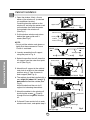
Cabinet Installation
1. Open the window. Mark a line on
center of the window sill (or desired
air conditioner location).
Carefully place the cabinet on the
window sill and align the center mark
on the bottom front with the center
line marked in the window sill.
(See Fig.1)
Upper Guide
Window sill
Front Angle
Fig.
Window Sash
2. Pull the bottom window sash down
behind the upper guide until it
meets.(See Fig.2)
Upper guide
Foam-pe 10
Cabinet
Frame Curtain
NOTE:
• Do not pull the window sash down so
tightly that the movement of Frame
Curtain is restricted.
1
Fig. 2
INDOOR
OUTDOOR
Sill Support
4. Select the position that will place the
sill support near the outer most point
on sill (See Fig. 4)
Nut
3
Fig. 3
4
Screw (Type A)
5
About 12.7 mm (1/2")
Bolt
2
Frame Guide
5. Attach the sill support to the cabinet
track hole in relation to the selected
position using 2 Type A screws in
each support (See Fig. 4).
Cabinet
INDOOR
6. The cabinet should be installed with a
very slight tilt (about 12.7 mm(1/2"))
downward toward the outside (See
Fig. 5).
Adjust the bolt and the nut of sill
support for balancing the cabinet.
OUTDOOR Fig. 4
Screw (Type B)
6
Sill support
7. Attach the cabinet to the window sill
by driving the screws
(Type B)
through the front angle into window
sill.
2
About 12.7 mm (1/2")
3. Loosely assemble the sill support
using the parts in Fig. 3.
Features and Installation
1
Sash track
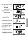
8. Pull each Frame curtain fully to each
window sash track, and repeat step 2.
Front Angle
Screw (Type B)
Sill support
12
2
6
Fig. 5
9. Attach each Frame curtain to the window
sash using screws
(Type C). (See Fig. 6)
Type C
CAUTION: DO NOT DRILL A HOLE IN THE
BOTTOM PAN.
The unit is designed to operate
with approximately 12.7 mm (1/2")
of water in bottom pan.
7
Fig. 6
10. Slide the unit into the cabinet. (See Fig. 7)
CAUTION: For security purposes, reinstall
screws at cabinet's sides.
Power cord
Screw
Screw
Fig. 7
Foam-Strip
11. Cut the foam-strip
to the proper length
and insert between the upper window sash
and the lower window sash.
(See Fig. 8)
Fig. 8
9
with
Fig. 9
13. Attach the front grille to the cabinet by
inserting the tabs on the grille into the tabs
on the front of the cabinet. Push the grille
in until it snaps into place. (See Fig.10)
NOTE: Please refer to p.7 for setting
ventilation kit.
Fig. 10
14. Lift the inlet grille and secure it with two
type A screws through the front grille.
(See Fig. 11)
15. Window installation of room air conditioner
is now completed. See ELECTRICAL DATA
for attaching power cord to electrical outlet.
Fig. 11
13
Features and Installation
Window locking bracket
12. Attach the window locking bracket
a type C screw. (See Fig. 9)
8
Electrical Data
Power cord may include a current interrupter device. A test and reset button is provided on the plug
case. The device should be tested on a periodic basis by first pressing the TEST button and then the
RESET button. If the TEST button does not trip or if the RESET button will not stay engaged,
discontinue use of the air conditioner and contact a qualified service technician.
Damaged power supply cord must be replaced with a new power supply cord obtained from the product
manufacture and not repaired.
Use Wall Receptacle
Standard 125V, 3-wire grounding
receptacle rated 15A, 125V AC
Power Supply
Use 15 AMP. time
delay fuse or 15 AMP.
circuit breaker.
USE OF EXTENSION CORDS
Because of potential safety hazards, we strongly discourage the use of an extension cord. However, if you wish to
use an extension cord, use a CSA certified/UL-listed 3-wire (grounding) extension cord, rated 15A, 125V.
Features and Installation
All wiring should be made in accordance with local electrical codes and regulations.
NOTE : Aluminum house wiring may pose special problems. Consult a qualified electrician.
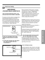
ELECTRICAL SAFETY
IMPORTANT GROUNDING INSTRUCTIONS
Air conditioner has a three-prong grounding plug on its power supply cord, which must be plugged into
properly grounded three-prong wall receptacle for your protection against possible shock hazard.
14
Electrical Safety
IMPORTANT
(PLEASE READ CAREFULLY)
Because of potential safety hazards, we strongly
discourage the use of an adapter plug. However, if
you wish to use an adapter, a TEMPORARY
CONNECTION may be made. Use UL-listed
adapter, available from most local hardware stores
(Fig. 13). The large slot in the adapter must be
aligned with the large slot in the receptacle to
assure a proper polarity connection.
FOR THE USER'S PERSONAL SAFETY, THIS
APPLIANCE MUST BE PROPERLY GROUNDED
The power cord of this appliance is equipped with a
three-prong (grounding) plug. Use this with a
standard three-slot (grounding) wall power outlet
(Fig. 12) to minimize the hazard of electric shock.
The customer should have the wall receptacle and
circuit checked by a qualified electrician to make
sure the receptacle is properly grounded.
CAUTION: Attaching the adapter ground terminal to
the wall receptacle cover screw does not ground the
appliance unless the cover screw is metal, and not
insulated, and the wall receptacle is grounded
through the house wiring.
The customer should have the circuit checked by a
qualified electrician to make sure the
receptacle is properly grounded.
PREFERRED METHOD
Ensure proper ground
exists before use
Fig. 12
B. SITUATIONS WHERE THE APPLIANCE
WILL BE DISCONNECTED OFTEN.
Do not use an adapter plug in these situations.
Unplugging the power cord frequently can lead to
an eventual breakage of the ground terminal. The
wall power outlet should be replaced by a three-slot
(grounding) outlet instead.
DO NOT CUT OR REMOVE THE THIRD
(GROUND) PRONG FROM THE POWER
PLUG.
A. SITUATIONS WHERE THE APPLIANCE
WILL BE DISCONNECTED ONLY
OCCASIONALLY:
USE OF EXTENSION CORDS
TEMPORARY METHOD
Because of potential safety hazards, we strongly
discourage the use of an extension cord. However,
if you wish to use an extension cord, use a CSA
certified/UL-listed 3-wire (grounding) extension
cord, rated 15A, 125V.
Adapter plug
Metal screw
Receptacle cover
Fig. 13
15
Features and Installation
Disconnect the power cord from the adapter, using
one hand on each. Otherwise, the adapter ground
terminal might break. DO NOT USE the appliance
with a broken adapter plug.
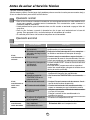
Before you call for service...
Troubleshooting Tips
Save time and money! Review the chart below first and you may not need to call for service.
Normal Operating
• You may hear a pinging noise caused by water being picked up and thrown against the condenser
on rainy days or when the humidity is high. This design feature helps remove moisture and improve
efficiency.
• You may hear the thermostat click when the compressor cycles on and off.
• Water will collect in the base pan during high humidity or on rainy days. The water may overflow
and drip from the outdoor side of the unit.
• The fan may run even when the compressor does not.
Abnormal Operation
Problem
Air conditioner
does not start
Before you call for service...
Air conditioner
does not cool as it
should
Air conditioner
freezing up
Possible Causes
What To Do
■ The air conditioner is
unplugged.
• Make sure the air conditioner plug is pushed
completely into the outlet.
■ The fuse is blown/circuit
breaker is tripped.
• Check the house fuse/circuit breaker box and
replace the fuse or reset the breaker.
■ Power failure.
• When power is restored, wait 3 minutes to restart the
air conditioner to prevent tripping of the compressor
overload.
■ The current interrupter
device is tripped.
• Press the RESET button located on the power cord plug.
• If the RESET button will not stay engaged,
discontinue use of the air conditioner and contact a
qualified service technician.
■ Airflow is restricted.
• Make sure there are no curtains, blinds, or furniture
blocking the front of the air conditioner.
■ TEMP Control is set at too
high a number.
• Set the TEMP Control to a lower number.
■ The air filter is dirty.
• Clean the filter at least every 2 weeks.
See the operating instructions section.
■ The room may have been
hot.
• When the air conditioner is first turned on
you need to allow time for the room to cool down.
■ Cold air is escaping.
• Check for open furnace floor registers
and cold air returns.
• Set the air conditioner's vent to the closed position.
■ Cooling coils have iced up.
• See Air Conditioner Freezing Up below.
■ Ice blocks the air flow and
stops the air conditioner
from cooling the room.
• Set the mode control at High Fan or High Cool with
the high temperature.
16
MEMO
17
Precauciones Importantes de seguridad
Instrucciones de Funcionamiento
Instrucciones de
Funcionamiento
Antes de avisar al Servicio Técnico
Características e Instalacion
Precauciones
Importantes de
Seguridad
Precauciones Importantes
de seguridad ....................19
PARA SU INFORMACION
Escriba aquí los números de serie y modelo de las
unidades exterior e interior:
Nº de Modelo
Nº Serie
Los números figuran en una etiqueta en el lateral de cada
unidad.
Distribuidor
Fecha de compra
Controles ...........................21
Control remoto...................22
Ventilación.........................23
Como controlar la
direccion del aire ...............23
Como installar el Tubo de
Desagüe ............................23
LEA ESTE MANUAL
Limpieza de filtro de aire...24
• Aquí encontrará numerosas sugerencias sobre cómo
utilizar y mantener adecuadamente su acondicionador de
aire. Con unos cuantos cuidados preventivos se puede
ahorrar mucho tiempo y dinero a lo largo de la vida útil de
su acondicionador de aire.
• En la tabla de sugerencias para la resolución de
problemas encontrará respuestas a la mayoría de los
problemas más comunes. Si consulta primero la tabla de
Sugerencias para la resolución de problemas, quizá ni
siquiera necesite avisar al servicio técnico.
Características
PRECAUCION
Cuidado y Mantenimiento
Características ..................25
Instrucciones de
instalación
Elija el major lugar.............26
Requisitos de ventana.......26
Contenido del juego de
instalación ..........................27
Requisitos de las herra
mientas sugeridas...............27
Instalación del Gabinete....28
Datos Electricos ................30
Informacion Electrica.........31
• Consulte con el servicio técnico autorizado sobre la
reparación o el mantenimiento de esta unidad.
• El acondicionador de aire no debe ser utilizado por
niños pequeños o personas inestables sin
supervisión.
• Es preciso vigilar a los niños pequeños para
asegurarse de que no juegan con el acondicionador
de aire.
Antes de avisar al
Servicio Técnico
Operacíon normal ............32
Operacíon anormal ..........32
18
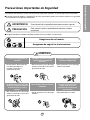
Para prevenir tanto lesiones al usuario u otras personas como daños materiales, es preciso seguir estas instrucciones.
■ El manejo incorrecto debido a la inobservancia de estas instrucciones puede causar lesiones o daños cuya gravedad
está clasificada en las siguientes indicaciones.
ADVERTENCIA
Este símbolo indica la posibilidad de lesiones mortales o graves.
PRECAUCION
Este símbolo indica la posibilidad de lesiones o daños
materiales.
■ El significado de los símbolos utilizados en este manual se indica a continuación.
Asegúrese de no hacerlo.
Asegúrese de seguir las instrucciones.
ADVERTENCIA
Conecte correctamente el
enchufle
No opere o pare la unidad
insertando o tirando del
enchufe
No dañe o utilize un cable
eléctrico inadecuado
• De otra forma, ello ocasionaría
una descarga eléctrica o
incendio a causa de la
generación de calor.
• Ello ocasionaría una descarga
eléctrica o incendio a causa de la
generación de calor.
• Ello ocasionaría una descarga
eléctrica o incendio.
No modifique el largo del cable
eléctrico, y tampoco comparta
el tomacorriente con otros
aparatos
No lo maneje con las manos
humedas
No exponga durante mucho
tiempo la piel al aire frío
procedente directamente del
acondicionador.
• Ello ocasionaría una descarga
eléctrica o incendio a causa de la
generación de calor.
• Puede ocasionar una descarga
eléctrica.
19
• Esto podría dañar su salud.
Precauciones Importantes de seguridad
Precauciones Importantes de Seguridad
Precauciones Importantes de seguridad
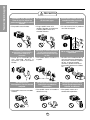
PRECAUCION
Cuando se vaya a quitar el
filtro de aire no toque las
partes metálicas de la unidad
interior.
No limpie el acondicionador
de aire con agua.
Ventile bien cuando utilice el
acondicionador junto con
una estufa, etc.
• El agua podría entrar en la
unidad y degradar el aislamiento.
También podría causar una
sacudida eléctrica.
• En este caso tal vez se produzca
una falta de oxígeno.
Cuando limpie la unidad,
desconecte la alimentación y
desconecte también el
disyuntor.
NO ponga un animal doméstico
ni una planta donde quede
directamente expuesto al flujo
de aire.
No lo utilice para propósitos
especiales.
• Puesto que el ventilador gira a
alta velocidad durante la
operación, podría ocasionar
heridas.
• Esto podría dañar al animal o a
la planta.
• No utilice este acondicionador de
aire para conservar dispositivos
de precisión, alimentos y objetos
de arte; no ponga tampoco
animales y plantas cerca de él.
Esto podría deteriorar la calidad,
etc.
No manipule los
interruptores con las manos
mojadas.
No aplique aerosoles con
insecticida o productos
inflamables.
No ponga una estufa, etc.
donde quede expuesta al
flujo de aire directo.
• Esto podría causar una sacudida
eléctrica.
• Esto podría causar un incendio o
deformar la caja.
• Esto podría causar heridas.
20
• Esto podría causar una
combustión imperfecta.
Instructions de Fonctionnement
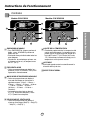
Controles
Modelo: CW-XC85HU
Modelo: CW-XC65HU
7
F
4
hr
FAN
SPEED
TIMER
4
ECONOMY
FAN COOL
2
AIR
SWING
6
OFF/ON
1
ECONOMY
FAN COOL
AIR
SWING
DRY
TIMER
OFF/ON
MODE
OPERATION
OPERATION
TEMP
5
3
2
5
AJUSTE DE LA TEMPERATURA
• Este botón puede controlar la temperatura del
cuarto automáticamente. La temperatura se
puede ajustar de grado en grado, desde 60˚F
hasta 86˚F cada 1˚F (16˚C hasta 30˚C cada
1˚C). Seleccione el número más bajo para la
temperatura más baja en el cuarto.
ENECNDIDO/APAGADO
• Para ENCENDER el sistema presione el
botón, y para APAGARLO presione el
botón otra vez.
• Este botón tiene prioridad sobre todos los
otros botones.
• Cuando Ud. Io enciende por primera vez,
el sistema está en el y la temperatura es
de 72˚F (22˚C).
AUTOGIRO
Este botón puede controlar automáticament la
dirección del flujo de aire.
FRÍO/VENTILADOR
• Cada vez que presione este botón, las
palabras COOL, ECONOMY, FAN y DRY
aparecerán alternadamente.
RECEPTOR DE SEÑAL
MARCADOR DE ENCENDIDO/APAGADO
• Cada vez que presione este botón, el
marcador de tiempo se ajustará de la
siguiente manera: (1Hora → 2 Horas →
3 Horas → 4 Horas → 5 Horas → 6 Horas
→ 7 Horas → 8 Horas → 9 Horas →
10 Horas → 11 Horas → 12 Horas →
Cancelar).
• La temperatura de ajuste se elevará
2˚F(1˚C), 30 minutos después, y otros
2˚F(1˚C)media hora después.
VELOCIDAD DEL VENTILADOR
• Cada vez que presione este botón, el
ajuste es como sigue {Alto(F3) → Bajo(F1)
→ Alto(F2) → Alto(F3)...}
21
1
Instrucciones de Funcionamiento
MODE
TEMP
3
FAN
SPEED
TIMER
DRY
TIMER
7
F
hr
Control remoto
Precaución: El dispositivo de control remoto no funcionará adecuadamente si la ventana sensora del acondicionador de aire es
expuesta a luz fuerte, o si hay obstáculos entre el dispositivo de control remoto y el acondicionador de aire.
Modelo: CW-XC85HU
Modelo: CW-XC65HU
OPERATION
OPERATION
Instrucciones de Funcionamiento
1
1
TEMP
TIMER
3
TEMP
AIR
SWING
5
7
MODE
FAN SPEED
2
5
TIMER
3
MODE
4
2
FAN SPEED
4
ECONOMY
ECONOMY
6
6
ENECNDIDO/APAGADO
• Para ENCENDER el sistema presione el botón, y para
APAGARLO presione el botón otra vez.
• Este botón tiene prioridad sobre todos los otros botones.
• Cuando Ud. Io enciende por primera vez, el sistema está
en el y la temperatura es de 72˚F(22˚C).
VELOCIDAD DEL VENTILADOR
• Cada vez que presione este botón, el ajuste es
como sigue. {Alto(F3) → Bajo(F1) → Alto(F2) →
Alto(F3)...}
AJUSTE DE LA TEMPERATURA
• Este botón puede controlar la temperatura del
cuarto automáticamente. La temperatura se puede
ajustar de grado en grado, desde 60˚F hasta 86˚F
cada 1˚F (16˚C hasta 30˚C cada 1˚C). Seleccione
el número más bajo para la temperatura más baja
en el cuarto.
FRÍO/VENTILADOR
• Cada vez que presione este boton, las palabras COOL,
ECONOMY,FAN y DRY aparecerán alternadamente.
MARCADOR DE ENCENDIDO/APAGADO
- OPERACIÓN DE PARADA:
• Cada vez que presione este botón, cuando el sistema
esté operando, el marcador de tiempo se ajustará de la
siguiente manera: (1Hora → 2 Horas → 3 Horas →
4 Horas → 5 Horas → 6 Horas → 7 Horas → 8 Horas →
9 Horas → 10 Horas → 11 Horas → 12 Horas → 0).
• La temperatura de ajuste se elevará 2˚F(1˚C),
30 minutos después, y otros 2˚F(1˚C) media hora
después.
- OPERACIÓN DE INICIACIÓN:
• Cada vez que presione este botón, cuando el sistema
esté operando, el marcador de tiempo se ajustará de la
siguiente manera: (1Hora → 2 Horas → 3 Horas →
4 Horas → 5 Horas → 6 Horas → 7 Horas → 8 Horas →
9 Horas → 10 Horas → 11 Horas → 12 Horas → 0).
AHORRADOR DE ENERGÍA
El ventilador se detiene cuando el compressor no
sigue enfriando.
• Aproximadamente cada 3 minutos el ventilador se
encenderá, y necesitará verificar la temperatura
del cuarto para saber si es necesario más
enfriamiento.
AUTOGIRO
Este botón puede controlar automáticament la
dirección del flujo de aire.
DRY
Cuando esta unidad se torna al modo seco, el
ventilador gira en velocidad lenta. El ventilador se
detiene cuando el compresor se para de enfriar.
Aproximadamente cada 3 minutos se encendera el
ventilador y la unidad comprueba la temperatura del
aire de la habitacion para ajustarse a si mismo.
22
Controles adicionales e informacion importante.
Ventilación
La palanca de ventilación debe estar en posición CERRADA para poder mantener las
mejores condiciones de enfriamiento. Cuando se necesite aire fresco en la habitación,
coloque la palanca de ventilación en posición ABIERTA. La Compuerta es abierta y el
aire de la habitación es expulsado.
CERRADO
NOTA: Antes de utilizar la característica de ventilación, haga un kit de ventilación.
Primero, hale hacia abajo la parte hasta que quede horizontal con la parte .
VENT
ABIERTO
Parte B
Parte A
La dirección del aire puede ser controlada cuando usted desee enfriar, ajustando la
palanca vertical y la palanca horiziontal.
• CONTROL DE LA DIRECCIÓN HORIZONTAL DEL AIRE
• CONTROL DE LA DIRECCIÓN VERTICAL DEL AIRE
Controlado
por manual
Controlado por
Director Remoto
(Modelo:CW-XC85HU)
Controlado
por manual
La dirección vertical del aire es
ajustada rotando la palanca horizontal
hacia adelanto o hacia atrás.
La dirección horizontal del aire es ajustada
rotando la palanca vertical hacia la derecha o
hacia la izquierda manualmente o por Director
Remoto.
Como Installar el Tubo de Desagüe
En climas húmedos, es posible que la BANDEJA EVAPORADORA se llene de agua.
Para quitar el agua acumulado, es preciso conectar el tubo de desagüe.
Quite la TAPA DEL DESAGÜE y conecte el TUBO a la BANDEJA EVAPORADORA.(Ver Fig.1)
Opcional(CW3H02502C)
1. Retire el tapón de plástico y deslice el chasis fuera
del armario. (Ver Fig. 2)
2. Instale la bandeja de drenaje por encima de la
esquina de la tapa de donde retiró el tapón con 4 (o
2) tornillos.(Ver Fig. 3)
3. Conecte la manguera de drenaje a la salida situada
en la parte inferior de la bandeja de drenaje. Puede
adquirir una manguera de drenaje o una tubería
apropiada en su localidad que satisfaga sus
necesidades particulares (la manguera no se
suministra).(Ver Fig. 3)
4. Seleccione la conexión más apropiada entre las
figuras siguientes (teniendo en cuenta el orificio de la
unidad) para acoplar la bandeja de drenaje en su
unidad.(Ver Fig. 3)
5. Deslice el chasis en el interior del armario.
Vuelva a apretar los tornillos del armario. Fije el
armario al chasis con tornillos.(Ver Fig. 4)
Tapa
del desagüe
Tubo
Fig. 1
OPERATION
TIMER
OFF/ON
SET
F
TE P/TI
SET/E
C N
ECONOMY
AIR
COOL
MO
E
FAN
HIGH
MED FAN
rol
Wireless
Cont
SPEED
Remote
LOW
Retire el tapón
de goma
Fig. 2
TAPA
MANGUERA DE DRENAJE
El diámetro
interior 17mm (5/8")
BANDEJA
DE DRENAJE
TORNILLOS
F
hr
TIMER
TEMP/TIMER
FAN
OPERATION
SET
SET/
CANCEL
COOL
Fig. 3
OFF/ON
MODE
AIR SWING
HIGH
MED
LOW
ECONOMY
FAN SPEED
Wireless
Remot
e Cont
r
ol
Fig. 4
23
Instrucciones de Funcionamiento
Como controlar la direccion del aire
Cuidado y Mantenimiento
APAGUE EL AIRE ACONDICIONADO Y SAQUE EL ENCHUFE DEL TOMA CORRIENTE DE LA PARED.
Limpieza de filtro de Aire
El filtro de aire detrás de la rejilla frontal debe ser revisado y limpiado por lo menos una
vez por cada dos semanas o más frecuentemente si es necesario.
La rejilla es diseñado para limpiar el filtro tanto hacia arriba como hacia abajo.
Instrucciones de Funcionamiento
PARA REMOVER:
1. Abra la rejilla hacia arriba tirando la parte inferior de la rejilla o hacia abajo tirando la
parte superior de la rejilla.
2. Usando una lengüeta, tire el filtro ligeramente hacia arriba para sacarlo por abajo o
arriba.
3. Limpie el filtro con agua tibia y jabonosa bajo 40°C (104°F).
4. Enjuague y sacuda el filtro suavemente bajo la corriente de agua y déjelo secar antes
de reponerlo.
PRECAUCION: NO OPERE el aire acondicionado sin filtro ya que la suciedad y el tamo
obstruirá el filtro y reducirá la eficiencia del funcionamiento.
Cómo poner las baterías
1. Quite la tapa de la parte posterior del telemando.
Para ello haga deslizar la tapa según la dirección
del la flecha.
2. Introduzca las dos AAA célula seca baterías,
asegurándose de que las direcciones (+) y (-)
estén colocadas correctament. Use baterías
nuevas.
3. Volver a cerrar, resbalando la tapa hasta la
posición inicial.
24
• No utilice baterís
recargables, éstas son
diferentes de forma, de
dimensión y uso respecto a
las baterías secas usuales.
• Seque las baterías del
telemando cuando el
acondicionador no vaya a
ser usado durante un largo
período.
• No deje el control remoto a
mano de ninos y bebes
para que no absorben las
baterias.
Características
Aprender el nombre de las partes antes de la instalación le ayudará a entender el proceso
de instalación.
Características
DEFLECTOR DE AIRE HORIZONTAL
(VENTANILLAS HORIZONTALES)
DEFLECTOR HORIZONTAL DE AIRE
(VENTANILLAS VERTICALES)
SALIDA DE AIRE
GABINETE
REJILLA FRONTAL
RECOLECTOR DE AIRE
(BANDEJA DE ENTRADA)
FILTRO DE AIRE
Modelo: CW-XC85HU
SUSPENSORES
COMPRESOR
CONDENSADOR
EVAPORADOR
PANEL DE CONTROL
BANDEJA
F
FAN
SPEED
hr
TIMER
ECONO
MY
FAN
COOL
DRY
TIMER
AIR
SWING
MODE
OFF/O
N
CONTROL REMOTO
CABLE DE CONEXIÓN ELÉCTRICA
Modelo: CW-XC65HU
SUSPENSORES
COMPRESOR
CONDENSADOR
EVAPORADOR
BANDEJA
F
FAN
hr
SPEED
TIMER
PANEL DE CONTROL
ECONO
MY
TIMER
FAN
COOL
DRY
AIR
SWING
MODE
OFF/O
N
CABLE DE CONEXIÓN ELÉCTRICA
CONTROL REMOTO
25
Características e Instalacion
VENTANILLAS VERTICALES
Instrucciones de Instalación
Elija el major lugar
Cerca
Pabellón
Aire frio
Radiacion
de calor
30"~60"
1. Para prevenir la vibración y el ruido,
asegure de que la unidad esté instaalada
segura y firmemente.
2. Instale la unidad donde el sol no refleje
directamente en la unidad.
3. La salida debe extenderse hacia afuera por
lo menos 11" y no debe haber obstáculos,
como cercas o paredes, en 20" de la parte
de atrás del gabinete porque va ha prevenir
la rediación de calor del condensador.
Restriciones del aire de afuera reducirá
grandemente la eficiencia del aire
acondicionado.
Aproximamente 1/2"
Over 20"
CUIDADO: Todas las ventanillas de los lados
del gabinete deben mantenerse
expuestas hacia afuera de la
estructura.
4. Instale la unidad un poco inclinada de tal forma que la parte trasera esté ligeramente
más baja que el frente(cerca de 1/2").
Esto forzará el agua del condensador hacia afuera.
Características e Instalacion
5. Instale la unidad con la parte inferior cerca de 30"~60" arriba nivel de suelo.
Requistios de ventana
Esta unidad está diseñada para que sea
instalada en ventanas dobles estándares con
una abertura actual de ancho desde 22" a
36".
La parte superior e inferiro de la ventana
debe abrir lo suficiente para permitir una
abertura vertical libre de 15" desde la parte
inferior de la ventana hasta la base de la
misma.
22" a 36"
Taburete
15" min
(Con cubierta de armazon)
1/2" a 11/4"
Aiféizar
Interior pared
18 1/2" min
(Sin cubierta de armazon)
26
Retallo
Exterior
Contenido del Juego de Instalación
2
1
5
6
3
4
7
8
NO.
1
2
3
4
5
6
7
8
9
10
11
10
9
NOMBRE LA PARTE
CANTIDAD
PANEL GUÍA
2
SOPORTE DE ALFÉIZAR
2
TORNILLO
2
TUERCA
2
TORNILLO(TIPO A) 10mm (25/64")
13
TORNILLO(TIPO B) D5.1mm (3/16")/16mm (5/8")
3
TORNILLO(TIPO C) D4.1mm (5/32")/16mm (5/8")
5
TIRA DE GOMA
1
CHAPA DE SOPORTE PARALA VENTANA
1
BANDA ADHESIVA (920mm x 30mm x 2mm)
1
TAPA DEL DESAGÜE
1
11
Requisitos de las herra mientas sugeridas
DESARMADOR (+, -), REGLA, CUCHILLO, MARTILO, LAPIZ, NIVEL
Tornillos para
transporte
PREPARACION DEL CHASIS
Características e Instalacion
1. Remueva los tornillos cuales sujetan el
gabinete a ambos lados y en la parte de atrás.
2. Deslice la unidad fuera del gabinete tomando
el agarradero de la bandeja y hale hacia el
frente mientras mantiene el gabinete.
3. Corte el marco de la ventana con el largo
apropiado. Desprenda la parte de atrás y
sujete el Banda adhensiva
en la parte
inferior del marco de la ventana.
4. Inserte los paneles guías
superior.
en la guía
5. Sujete el armazon a la unidad con 4 tornillos.
(Tipo A)
10
(Tipo A)
5
5
Guía mas baja
5
27
(Tipo A)
Instalación del Gabinete
1. Abra la ventana. Marque una línea en el
centro del banqueta de la ventana(o la
ubicación deseada del aire acondicionado).
Cuidadosamente ubique el gabinete en la
banqueta de la ventana y alinee la marca
central en el frente inferior con el centro de la
línea marcada en la banqueta de la ventana.
(Ver Fig. 1)
2. Hale hacia abajo la parte inferior de la
ventana hasta que se una detrás de la guía
superior.(Ver Fig. 2)
Guía Superior
Taburete de la Ventana
Angulo de Delante
Fig. 1
Marco de Ventana
Banda adhesiva
Gabinet
Panel Guía 1
NOTA:
• No hale la ventana hacia abajo tan
apretadamente que el movimiento del panel
guía sea restringido.
Fig. 2
Interior
Exterior
3. Ligeramente ensamble el soporte del alfeizar
usando las partes de la fig. 3.
Soporte del Alféizar 2
Tornillo 3
4. Seleccione la posición que ubicará el soporte
del alféizar cerca del punto más exterior del
alféizar.(Ver Fig. 4)
Fig. 3
Tuerca 4
5. Pegue el soporte antepecho a los rieles de la
caja en relacion a la posicion deseada
usando dos tornillos Tipo A en cada soporte.
(Ver Fig. 4)
Gabinete
Exterior
Interior
Fig. 4
Tornillo(Tipo B) 6
6. El gabinete debe ser instalado con una
pequeña caída(cerca de 1/2") hacia abajo
hacia afuera (Ver Fig. 5).
Soporte del Alféizar 2
7. Adjunte el gabinete al banquete de la ventana
atornillando los tornillos (Tipo B: Largo
dieciséis milímetros y menos.) a través del
ángulo frontal en la banqueta de la ventana.
Aproximamente 1/2"
Tornillo(Tipo A) 5
Guia Marco 9
Aproximamente 1/2"
Características e Instalacion
Guía Superior
Pista de
Marco
8. Hale cada panel guía completamente a cada
lado de la ventana y repita del paso 2.
Angulo de Delante
Tornillo(Tipo B) 6
Soporte del Alféizar 2
28
Fig. 5
9. Adjunte cada panel guía a cada lado de la
(Tipo C).
ventana usando tornillos
(Ver Fig. 6)
Tipo C
PRECAUCION: No perfore la charola del fondo. La
unidad está diseñada para operar
con aproximadamente 1/2" de agua
en la charola del fondo.
7
Fig. 6
10. Deslice el chasís dentro del gabinete.
(Ver Fig. 7)
Conrdon
de Alimentacion
CUIDADO: Por razones de seguridad, re
instale los tornillos en los lados del
gabinete.
Tornillo
Tornillo
11. Corte la tira de goma
a la medida
apropiada e introdúzcala entre la parte
superior e inferior de la ventana.
(Ver Fig. 8)
Fig. 7
Tira de Goma
8
Fig. 8
Chapa de soporte para
la ventana 9
Fig. 9
13. Pegue el panel frontal a la caja insertando
los fijadores en el panel adentro los del
panel de la caja. (Ver Fig. 10)
NOTA: Se refiere por favor p.40 para poner
juego de ventilación.
Fig. 10
14. Levante la parrilla de entrada y ajústela
con tornillos Tipo A, através de la parrilla
frontal. (Ver Fig. 11)
15. Ahora la instalación del aire acondicionado
en la ventana es completada. Vea los DATOS
ELECTRICOS para instalar el cable de
alimentación en la toma de corriente.
Fig. 11
29
Características e Instalacion
12. Sujete la chapade soporte en el marco de
la ventana
con untornillo tipo C.
(Ver Fig. 9)
Datos Electricos
El cable de alimentación puede incluir un dispositivo interruptor de corriente. La carcasa del enchufe
cuenta con un botón de prueba y otro de reinicio. El dispositivo debe comprobarse periódicamente
presionando primero el botón TEST y después RESET. Si el botón TEST no se desconecta o si el
botón RESET no permanece activo, suspenda el uso del aire acondicionado y póngase en contacto
con un técnico de servicio cualificado.
Un cable de alimentación dañado debe sustituirse por uno nuevo proporcionado por fabricante del
producto y no reparado.
Utilice el enchufe de la pared
Standard 125V, enchufe de 3
Líneas de 15A, 125V AC
Consumo de Energía
Utilice un fusible de
15AMP. o un
Interruptor de 15AMP.
Características e Instalacion
USO DE CORDONES DE EXTENSION
Debido al potencial de peligro a su seguridad bajo ciertas circunstancias recomendamos encaredidamente
no utiliar cordones de extensión. Sin embargo, si usted decide usar un cordón de extensión, es
absolutamente necesario que este sea un cordón listado bajo UL de tres espigas con conexión a tierra
calificado 15A, 125V.
Todo el cableado deberá realizarse de acuerdo con los códigos y reglamentos eléctricos locales.
NOTA : El cableado doméstico de aluminio podría ocasionar problemas especiales. Consulte a un electricista calificado.
SEGURIDAD ELECTRICA
NSTRUCCIONES DE CONEXION A TIERRA IMPORTANTES
El aire acondicionado tiene una clavija de conexión a tierra de tres patas en su cable de suminstro de
energía, que deverá enchufarse en un tomacorriente de pared de tres paras conectado a tierra
adecuadamente para su protección contra un posible riesgo de electrocución.
30
Informacion Electrica
Debido al peligro potencial, nosotros no
recomendamos el uso de adaptadores. Sin
embargo, si usted desea utilizar un adaptador,
una CONEXIÓN TEMPORAL, puede ser
efectuada. Utilice adaptadores UL, disponibles
en la mayoría de los estable cimientos de
herramientas(Fig. 13). La pata mas grande del
adaptador debe ser alineada con la pata mas
grande del interruptor para asegurarse una
polarización adecuada.
IMPORTANTE
(FAVORLEA CON ATENCIÓN)
POR LA SEGURIDAD PERSONAL DEL
USUARIO, ESTE APARATO DEBE SER
DEBÍDAMENTE NEUTRALIZADO.
El cordón de energía de éste aparato esta
equipado con tres patas(cable a tierra). Utilice
éste con un enchufe de pared de tres salidas(a
tierra)(Fig. 12) para minimizar el peligro de
choque eléctrico. El cliente debe revisar el
receptor de pared y el circuito por un
electricista calificado para asegurarse que la
recepción esta debidamente neutralizada.
CUIDADO: Adaptar la terminal del ground del
adaptador a la cubierta de la pared con un
tornillo no neutraliza el aparato a menos que la
cubierta del tornillo sea de metal, u no sea
insolada, y el receptor de pared este
neutralizado a través del alambrado del la
casa. El cliente debe hacer verificar el circuito
por un electricista calificado para asegurarse
que el receptor esta debidamente neutralizado.
ASEGÚRESE QUE EXISTE
DEBIDA NEUTRALIZACIÓN ANTES
DE UTILIZAR EL APARATO.
Fig. 12
NO CORTE O REMUEVA LA TERCERA
PATA(GROUND) DEL ENCHUFE.
A. SITUACIONES EN LAS CUALES EL
APARATO ES DESCONECTADO
OCASIONALMENTE:
MÉTODO TEMPORAL
Desconecte el cordón de energía del
adaptador, utilizado una mano en cada uno.
De lo contrario, la terminal del adaptador
puede romperse. NO UTILICE el aparato con
un enchufe roto.
B. SITUACIONES EN LAS CUALES EL
APARATO ES DESCONECTADO CON
FRECUENCIA.
No utilice un adaptador en estas
circunstancias. Desconectar el cordón de
energía con frecuencia lo llevará al eventual
rompimiento de la terminal de neutralización.
La saluda de energía de la pared debe ser
reemplazada por una salida de tres
patas(neutralizada).
USO DE EXTENSIONES
Adaptador
Tornillo de metal
Cubierta del interruptor
Fig. 13
31
Debido al peligro potencial, no recomendamos
la utilización de extensiones. Sin embargo, si
usted desea utilizar una extensión, utilice una
certificada por CSA/UL de tres alambres,
catalogada 15A, 125V.
Características e Instalacion
Características e Instalacion
MÉTODO PREFERIDO
Antes de avisar al Servicio Técnico
Tips para solucionar problemas
(Ahorre temopo y dinero) Cuando tenga algún problema primero consulte el cuadro que se encuentra abajo y
tal vez no necesite llamar para solicitar servicio técnico.
Operación normal
• Durar te dias lluviosos o cuando la humedad es alta usted puede escuchar un ruido metállco causa
do por agua recogida y arrojada contra el condensador. Esta caracteristica ayuda a remover la
humedad y mejorar la eficiencia.
• Usted puede escuchar que el termostato hace un click cuando se enciende o apaga el ciclo del
comp esor.
• Durar te dias lluviosos o cuando la humedad es alta el agua será recolectada on la base del
aparato. Esta agua podrá fluir y será eliminada por el lado externo de la unidad.
• El ventilador podrá correr aún cuando el compresor no esté encendido.
Operación anormal
Probama
El aire
acondicionado no
enciende
El aire
acondicionado
enfria dernasiado
Que hacer
■ El aire acondicionado está • Asegúrese que ei aire acondicionado está conectado
completamente a la fuente de energia.
desconectado.
■ El fusible está quemado/el • Cheque los fusibles/interruptor de la casa y reemplace
interruptor de energía se ha los fusibles o reestablezca el interruptor de energía.
bloqueado.
• Cuando la energía se reestablezca, espere 3 minutos
■ Falta de energía.
para encender de nuevo el aire acondicionado. Con esto
evitará que se produzca una sobrecarga en el compresor.
■ El dispositivo interruptor de • Presione el botón RESET situado en el enchufe del cable
corriente está
de alimentación
desconectado.
• Si el botón RESET no permanece activo, suspenda el
uso del aire acondicionado y póngase en contacto con un
técnico de servicio cualificado.
■ El flujo de aire esta
restringido.
■ Coloque el control de
TEMPERATURA en un
número más alto.
• Asegúrese que no haya cortinas, persianas o muebles
bloqueando el frente del aire acondicionado.
• Gire el control de TEMPERATURA a un número más
bajo.
■ El filtro de aire está sucio.
• Limpie el filtro por lo menos cada dos semanas. Vea la
sección de instrucciones de operación.
• Cuando usted enciende el aire acondicionado debe
esperar un momento para que la habitación se enfrie.
• Asegúrese que todas las salidas de aire estén cerradas
para que el aire regrese.
• Coloque la ventana del aire acondicionado en la
posición más cercana.
• Establezca una temperatura más alta.
■ El cuarto aún está caliente.
.
■ El aire frio se está
escapando.
■ El serpentin de refrigeración
se ha congelado.
■ El hielo bloquea el flujo de
aire y detiene el
enfriamiento del cuarto.
• Ajustar el control de mode en 'Ventilación Alta' o
'Erfriamiento Alto' con la temperatura alta.
32
Before you call for service...
Antes de avisar al Servicio Técnico
El aire
acondicionado no
enfría corno
debiera
Causas posibles
MEMO
33
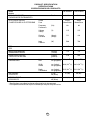
PRODUCT SPECIFICATION
SPÉCIFICATIONS
ESPECIFICIONES DEL PRODUCTO
Model
Modelo
COOLING CAPACITY
CAPACIDAD DE ENFRIAMIENTO
ELECTRICAL RATING
CLASIFICION DE LA ELECTRICIDAD
Btu/h
Phase
Fase
CW-XC65HU
CW-XC85HU
6,000
7,800
Single
Monofasico
Single
Monofasico
Frequency
Frecuencia
(Hz)
60
60
Voltage
Voltaja
(V)
115
115
Current
Corriente
(Amps)
(Amps)
5.2
6.6
Input
Potencia
(W)
560
720
10.7
10.8
EER
EER
MOISTURE REMOVAL
DESHUMIDIFICACION
(Pints/h)
(Tinta/h)
1.8
2.3
ROOM CIRCULATION
CIRCULACION DE AIRE
(Cf/min)
(pie/min)
170
226
DIMENSIONS
DIMENSIONES
Height
Alto
cm (inches)
cm (pulgadas)
35.3 (13 29/32)
35.3 (13 29/32)
Width
Ancho
cm (inches)
cm (pulgadas)
46.9 (18 15/32)
46.9 (18 15/32)
Depth
Profundidad
cm (inches)
cm (pulgadas)
52.5 (20 21/32)
52.5 (20 21/32)
NET WEIGHT
PESO NETO
kg (Ib)
kb (libras)
27 (60)
30 (66)
GROSS WEIGHT
PESO BRUTO
kg (Ib)
kb (libras)
30 (66)
33 (74)
* Specifications are subject to change without notice for improvement.
* Las especificacionas están sujetas a cambios por majoras sin previo aviso.
34
Panasonic Consumer Electronics Company,
Division of Panasonic Corporation of North
America
One Panasonic Way
Secaucus, New Jersey 07094
Division of Panasonic Puerto Rico, Inc.,
Ave. 65 de Infanteria, Km. 9.5
San Gabriel Industrial Park
Carolina, Puerto Rico 00985
Panasonic Room Air Conditioner
Limited Warranty
Panasonic Consumer Electronics Company or Panasonic Sales Company (collectively referred to as "the Warrantor") will repair
this product with new or refurbished parts in case of defects in material or workmanship, free of charge, in the USA or Puerto
Rico in accordance to the following (All time periods start from the date of the original purchase).
ALL COMPONENTS: (1) YEAR PARTS AND LABOR.
SEALED REFRIGERATING SYSTEM (compressor and interconnecting tube): (1) YEAR LABOR. (5) YEARS PARTS.
FOR YEARS 2 THROUGH 5, SERVICE AND LABOR COSTS WILL BE THE RESPONSIBILITY OF THE
CUSTOMER.
In-home service in the USA can be obtained during the warranty period by contacting Panasonic, toll free, at 1-800-211PANA(7262), to locate a PASC authorized Servicenter. In-home service in Puerto Rico can be obtained during the warranty
period by calling the Panasonic Sales Company telephone number listed in the Servicenter Directory.
Note: If the unit is installed at other than normal window height and/or has been
custom-installed (e.g., through the wall), the customer is responsible for removing
the unit from its installation prior to the performance of in-home service.
This warranty is extended only to the original purchaser. A purchase receipt or other proof of date of the original purchase is
required for service and parts replacement under this warranty.
This warranty only covers failures due to defects in materials and workmanship and does not cover normal wear or cosmetic
damage. The warranty does not cover damages which occur in shipment, or failures which are caused by products not supplied by
the warrantor, or failures which result from accident, misuse, abuse, neglect, mishandling, misapplication, faulty installation,
maladjustment of customer controls, improper maintenance, alteration, modification, power line surge, lightning damage,
improper voltage supply, commercial use such as hotel, office, restaurant, or other business or rental use of the product, or service
by anyone other than a PASC Factory Servicenter or a PASC authorized Servicenter, or damage that is attributable to acts of God.
LIMITS AND EXCLUSIONS
There are no express warranties except as listed above.
THE WARRANTOR SHALL NOT BE LIABLE FOR INCIDENTAL OR CONSEQUENTIAL DAMAGES RESULTING
FROM THE USE OF THIS PRODUCT, OR ARISING OUT OF ANY BREACH OF THIS WARRANTY. ALL EXPRESS AND
IMPLIED WARRANTIES, INCLUDING THE WARRANTIES OF MERCHANTABILITY, ARE LIMITED TO THE
APPLICABLE WARRANTY PERIOD SET FORTH ABOVE.
Some states do not allow the exclusion or limitation of incidental or consequential damages or limitations on how long an
implied warranty lasts, so the above exclusions or limitations may not apply to you.
This warranty gives you specific legal rights and you may also have other rights which vary from state to state If a problem with
this product develops during or after the warranty period, you may contact your dealer or Servicenter If the problem is not
handled to your satisfaction, then write to the Consumer Affairs Department at the company address indicated above
SERVICE CALLS WHICH DO NOT INVOLVE DEFECTIVE MATERIALS OR WORKMANSHIP AS DETERMINED BY
THE WARRANTOR, IN ITS SOLE DISCRETION, ARE NOT COVERED COSTS AND SUCH SERVICE CALLS ARE THE
RESPONSIBILITY OF THE PURCHASER.
[For assistance, please call: 1-800-21 1-PANA (7262) or contact us via the web at http://www.panasonic.com/contactinfo]
Printed in China