1
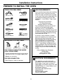
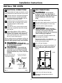
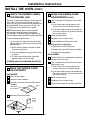
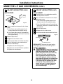
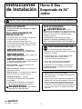
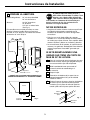
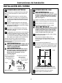
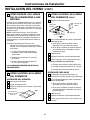
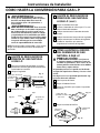
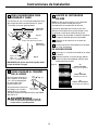
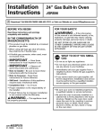
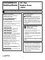
Installation
Instructions
24” Gas
Built-In Oven
JGRP20
Questions? Call 800.GE.CARES (800.432.2737) or Visit our Website at: www.GEAppliances.com
FOR YOUR SAFETY:
BEFORE YOU BEGIN
Read these instructions and warnings
completely and carefully.
WARNING
— If the information
in this manual is not followed exactly, a fire,
explosion or gas leak may result, causing
property damage, personal injury or death.
IN THE COMMONWEALTH
OF MASSACHUSETTS:
DO NOT STORE OR USE GASOLINE OR
OTHER FLAMMABLE VAPORS AND LIQUIDS
IN THE VICINITY OF THIS OR ANY OTHER
APPLIANCE!
• This product must be installed by a licensed
plumber or gas fitter.
• When using ball-type gas shut-off valves,
they shall be the T-handle type.
• A flexible gas connector, when used, must
not exceed 3 feet.
WHAT TO DO IF YOU
SMELL GAS:
•
IMPORTANT
— Save these
instructions for local inspector’s use.
• Do not try to light any appliance.
•
IMPORTANT
• Do not touch any electrical switch; do not
use any phone in your building.
•
IMPORTANT
• Immediately call your gas supplier from a
neighbor’s phone. Follow the gas supplier’s
instructions.
•
•
•
•
•
•
— Observe all
governing codes and ordinances.
— Leak testing of the
appliance shall be conducted according to
the manufacturer’s instructions.
Note to Installer – Be sure to leave these
instructions with the Consumer.
Note to Consumer – Keep these
instructions for future reference.
Skill level – Installation of this appliance
requires basic mechanical skills.
Completion time – 1 to 3 hours
Proper installation is the responsibility
of the installer.
Product failure due to improper installation
is not covered under the Warranty.
• If you cannot reach your gas supplier, call
the fire department.
Installation and service must be performed by
a qualified installer, service agency or the gas
supplier.
• Be sure your oven is installed properly by
a qualified installer or service technician.
• Be sure the oven is securely installed in a
cabinet that is firmly attached to the house
structure. Weight on the oven door could
cause the oven to tip, resulting in serious
personal injury or death. Never allow
anyone to climb, sit, lean, stand or hang
on the oven door.
WARNING
— This appliance must
be properly grounded.
229C4053P578
31-10584 12-03 JR
1
Installation Instructions
PREPARE TO INSTALL THE OVEN
TOOLS YOU WILL NEED
Drill with 1/8” Bit
1 GAS REQUIREMENTS
You must follow local codes when installing
your built-in oven. Check with your local
utilities for codes and ordinances that apply
in your area. If there are no local codes, you
must follow the National Fuel Gas Code
ANSI/Z223.1 – Latest Edition. To get a copy
write to:
Safety Glasses
Adjustable Wrench
Ruler or Straightedge
Pipe Wrench
Pencil
3/16” Hex Socket
Driver
12” Spirit Level
#1 or #2
Phillips Screwdriver
American Gas Association
1515 Wilson Boulevard
Arlington (Rosslyn), VA 22209
This standard does not cover the thermal
efficiency of household cooking gas
appliances since it is regulated by the
Energy Policy and Conservation Act of 1975,
the National Energy Conservation Policy Act
of 1978 and the National Appliance Energy
Conservation Act of 1987.
If the oven is to be installed in a mobile
home, the installation must conform to the
Manufactured Home Construction and
Safety Standard, Title 24, CFR, Part 3280 or,
when not applicable, the Standard for
Manufactured Home Installations ANSI/
A225.1 – Latest Edition and Manufactured
Home Installations, Sites and Communities
ANSI/NFPA 501A, or with local codes. You
can get a copy of the Federal Standard by
writing:
Hand or Saber Saw
MATERIALS YOU MAY NEED
Gas line
shut-off valve
Pipe joint sealant
1/2″ pipe nipple
FOR FLEXIBLE CONNECTION WHERE
LOCAL CODES PERMIT:
Office of Mobile Home Standards
HUD Building
451 7th Street, S.W.
Washington, D.C. 24010
• Coated and approved flexible metal tubing
(same 3/4″ or 1/2″ I.D. as gas supply line)
• Adaptor or connector
FOR RIGID CONNECTION:
2 ELECTRICAL REQUIREMENTS
• Pipe fittings or union as required
This appliance must be electrically
grounded. Check with your local codes
which apply in your area. If no local
codes apply, the National Electrical Code,
ANSI/NFPA No. 70 – Latest Edition must
be followed. Write to:
NATIONAL FIRE PROTECTION
ASSOCIATION
BATTERYMARCH PARK
QUINCY, MA 02269
2
Installation Instructions
The cabinet must have solid sides,
back and bottom. The bottom must
be solid either at floor level or with
the bottom edge of the cutout. Any
openings around the gas or electrical outlets
must be sealed. All cabinet openings must be
sealed at the time of installation to prevent
drafts. Drafts will affect safe use of the oven.
3 PREPARE THE OPENING
Cabinet space:
24″ min. depth
24″ min. width
Cutout:
22 3/16″ width
38″ height
3/8″ min. on either side
(See Fig. 2)
It’s best to use a template to make a straight cut.
Place the template on a level base line, 22″ to 28″
above the floor. This will place the oven cavity 36″
or 42″ above the floor.
24″
MIN.
SPECIAL NOTES:
• Make sure the oven is installed at the specified
height. The unit has been tested and approved for
installation, in accordance with safety standards at
this height.
24″
MIN.
• If the floor is to be the solid bottom, two runners,
centered within the cutout opening 11″ apart may
be used to support the oven. These runners must
support 130 lbs. and must be level and straight.
22 3/16″
38″
• The wall coverings, countertops and cabinets
around the oven should be able to withstand
temperatures of up to 200°F generated by
the oven.
39″
22″ to
28″*
2 Runners on
11″ Centers
IF YOU ARE REPLACING A UNIT
THAT HAS A CUTOUT HEIGHT
OF MORE THAN 38″:
23 3/4″
Fig. 1
* SHOULD BE ADJUSTED TO SUIT BOTH STANDARD
CABINETRY AND DESIRED OVEN WORKING HEIGHT.
A
Shut off the main gas supply before removing
the existing oven. Leave the gas off until the
new hookup is complete.
B
Measure how much your cutout height
exceeds 38″.
C
Raise your gas inlet pipe if necessary.
D
Remove the storage drawer.
E
Extend the leg levelers (using a 3/16″ hex
socket driver) by the amount measured in
Step B.
F
Insert the oven into the cutout and adjust the
levelers so that the oven racks are level and
the top of the control panel overlaps the top
of the cutout.
Oven
3/8″ MIN.
Wall or
Cabinet
Fig. 2
3/16″ Slotted
Hex Head
Fig. 3
Leg Leveler
3
Installation Instructions
INSTALL THE OVEN
4 ELECTRICAL CONNECTIONS
5 GAS CONNECTIONS
An adequate electrical supply and outlet must be
used to operate the electrical parts of your oven.
A
The oven cord has a three-prong plug and
must be used with a properly grounded
three-hole outlet with a standard 120 Volt,
60 cycle AC household current.
B
Install the electrical outlet below the oven
on the left side, in a location that is easily
reached through the cabinet doors
(see Fig. 6).
C
D
WARNING:
Do not operate
the burners of this oven when using L.P.
(bottled) gas before converting the pressure
regulator and burner orifice for L.P. gas
usage.
See page 2 for all gas requirements.
If you do not have a three-hole grounded
outlet, have a qualified electrician change
your old one.
A
Shut off the gas supply at the shut-off valve.
B
Remove the existing oven (if necessary).
C
Discard any old or used connectors.
WARNING:
Never reuse old
flexible connectors. The use of old flexible
connectors can cause gas leaks and
personal injury. Always use new connectors
when installing a gas appliance.
A grounding adaptor will be needed to
convert the old one until the outlet can be
replaced. This method is only temporary,
and a qualified electrician should test it to
be sure it meets requirements.
D
Always unplug the oven cord before making any
electrical repairs to the oven. When unplugging
the oven, always grasp the plug, never the cord.
To prevent any leaks, use a pipe joint
compound that resists the action of L.P. gas
on the male outside threads.
WARNING:
NEVER USE AN
EXTENSION CORD TO CONNECT THE OVEN
TO THE ELECTRICAL SUPPLY.
E
Use a 1/2″ gas inlet pipe.
F
The hole for the inlet pipe should be 8 1/2″
min. to 9 5/8″ max. right of the centerline
and 23″ behind the front surface of the
cabinet.
WARNING:
Do not under any
circumstances cut or remove grounding
prong from oven cord. Failure to provide
proper polarization may create a hazardous
condition.
Plug with ground prong
properly polarized and
grounded receptacle
N
22″
Fig. 6
8 1/2″
MIN.
9 5/8″
MAX.
Polarized receptacle
properly grounded
Metal Eyelet
Ground
22″
to
28″
L
Receptacle
Plate Mounting
Screw
Preferred Method
Fig. 4
Be sure no strain has been placed on the
connecting line assembly.
Temporary Method
13 1/2″
Recommended Main Shut-OFF Location
(The regulator also has a shut-off lever)
Fig. 5
4
G
Install a shut-off valve to the pipe.
H
Remove the storage drawer and the
oven door.
Installation Instructions
5 GAS CONNECTIONS (cont.)
I
Place the oven in the cutout.
J
Level the oven:
K
6 CHECK FOR LEAKS
WARNING:
DO NOT USE OPEN
FLAME TO CHECK FOR LEAKS!
1. Place a spirit level on one of the oven
racks.
A
Apply a soap solution to all connections:
supply line, manifold and oven.
2. If the oven is not level, adjust the leg
levelers.
B
Turn on the main gas supply.
C
Check for any bubbles to form.
3. Remove regulator cover at the back of
the storage drawer area by removing
4 screws.
D
Turn off main gas supply.
E
Stop any leaks found.
With the oven in place, the pressure
regulator inlet is accessible through the
opening in the main back.
F
Turn main gas supply on to make sure all
leaks were stopped.
G
Replace the regulator cover using the 4
screws previously removed.
Through this opening connect:
WARNING:
1. The flexible connection and the adaptor
(see Fig. 7).
ALL LEAKS MUST BE
STOPPED BEFORE ATTEMPTING TO LIGHT
BURNERS.
or
2. The rigid pipe connection and union to the
shutoff valve (see Fig. 8).
Pressure Regulator
with Built-In
Shut-Off
Valve
7 PRESSURE TEST INFORMATION
Adaptor
Flexible Connection
Regulator
Cover
A
The maximum allowable pressure for the
regulator is 14″ W.C.
B
The minimum pressure needed to check the
regulator setting is 11″ W.C. for L.P. gas and
5″ W.C. for Natural.
CAUTION:
The range and
its individual shutoff valve must be
disconnected from the gas supply piping
system during any pressure testing of the
gas supply system at test pressures in
excess of 1/2 psig (pound per square inch
gauge).
Fig. 7
FLEXIBLE HOOK-UP
Pressure Regulator
Union
The range must be isolated from the gas supply
piping system by closing its individual manual
shut-off valve during any pressure testing of the
gas supply system at test pressures equal to or
less than 1/2 psig.
Regulator
Cover
Fig. 8
RIGID HOOK-UP
L
Tighten the fitting.
WARNING:
DO NOT FORCE!
FORCING COULD DAMAGE THE FITTING,
TUBING OR CAUSE LEAKING.
5
Installation Instructions
INSTALL THE OVEN
(CONT.)
8 CHECK THE BURNER FLAMES
FOR NATURAL GAS
9 MAKE THE BURNER FLAME
ADJUSTMENTS (CONT.)
The oven is factory-adjusted for use with Natural
Gas in most areas. But, since the gas in some
areas may vary, you should check all adjustments
described below. If you are to use L.P. Gas, see
L.P. Adjustments at the back of this guide.
E
Use a screwdriver to loosen the air shutter
screw.
1. If the flames were yellow, open the air
shutter more than the original setting.
2. If the flames blew away or fluttered from
the burner, close the air shutter more than
the original setting.
NOTE: Bake and broil flame must be checked
with the door closed to properly check flame
characteristics. To properly check the bake burner,
the oven bottom and oven baffle must be removed.
F
Make the adjustment.
Turn on the bake or broil burner.
G
Retighten the air shutter screw.
H
Close the door and recheck the flame.
As you watch the flame with the oven door
closed, check the following through the oven
door window:
When the results are satisfactory:
1. Replace the orifice fitting cover.
1. Burner flames should not flutter or blow
away from the burner.
2. Replace the oven baffle (flame spreader).
2. They should be blue in color with no trace
of yellow.
3. Replace the oven bottom.
BROIL BURNER
3. The inner cone of the flame should be
approximately 1/2″ to 3/4″ long.
BURNERS SHOULD BE CHECKED FREQUENTLY.
A
The broil burner is located and accessible in
the top rear of the oven.
B
Use a screwdriver to loosen the air shutter
adjustment screw.
1. If the flames were yellow, open the air
shutter more than the original setting.
9 MAKE THE BURNER FLAME
ADJUSTMENTS
2. If the flames blew away or fluttered from
the burner, close the air shutter more than
the original setting.
BAKE BURNER
A
Open the oven door.
B
Remove the oven bottom.
C
Remove 4 screws to remove baffle (flame
spreader).
Fig. 9
Oven Bottom
Burner Baffle
D
Remove orifice fitting cover.
Orifice
Fitting
Cover
Air Shutter
Air Shutter
Screw
Fig. 10
6
C
Make the adjustment.
D
Retighten the air shutter screw.
E
Close the oven door and recheck the flame.
Installation Instructions
10 SECURE THE OVEN
11 RECHECK STEPS
IMPORTANT: Remove
Double check to make sure everything in this
guide has been completed. Rechecking steps will
ensure safe use of the oven.
all packing material and literature
from the oven before connecting
any electrical supplies.
A
Using a 1/8″ drill bit, drill holes through the
side trim and into the cabinet front.
B
With the screws provided, secure the oven
to the wall.
C
If the cabinet cutout is 38″ high, use the
short trim and attach to the bottom of the
front frame, with screws provided.
WARNING: The trim permits air
entry into the cabinet below the unit and
must not be blocked.
(If the cutout is higher than 38″, use the taller trim.)
7
Installation Instructions
MAKE THE L.P. GAS CONVERSION
WARNING: If you are using L.P.
1 ADJUST PRESSURE
REGULATOR FROM NATURAL
GAS TO L.P. (CONT.)
(bottled) gas, all the adjustments described
below must be made before you make any
burner adjustments or use the oven.
WARNING: This conversion must
be performed by a qualified installer or gas
supplier in accordance with the
manufacturer’s instructions and all codes
and requirements of the authority having
jurisdiction. Failure to follow instructions
could result in serious injury or property
damage. The qualified agency performing
this work assumes responsibility for the
conversion.
NOTE: Disconnect all electrical power and turn
off the gas supply at the shut-off valve before
beginning the conversion.
Remove regulator cover at the back of the
storage drawer area by removing 4 screws.
B
Locate the regulator.
Pressure Regulator
with Built-In
Shut-Off
Valve
Remove the retainer from the cap.
E
Turn the retainer over so L.P. is showing on
the bottom of the retainer.
F
Return the retainer inside the cap.
G
Replace the cap on the regulator.
H
Replace the regulator cover using the
4 screws that held the cover originally.
2 ADJUST BURNER ORIFICE
FROM NATURAL TO L.P. GAS
CAUTION: The adjustments in the
next column must be made before turning
on the burners. Failure to do so could result
in serious injury due to high flames and
toxic fumes.
1 ADJUST PRESSURE
REGULATOR FROM NATURAL
GAS TO L.P.
A
D
Your Broil burner is located in the upper portion
of the oven and is easilly accessible.
To access your Bake burner follow the steps
below:
Adaptor
Flexible Connection
A
Open the oven door.
B
Remove the oven bottom.
C
Remove 4 screws holding the oven baffle
(flame spreader).
Fig. 11
Regulator
Cover
FLEXIBLE HOOK-UP
C
Oven Bottom
Burner Baffle
Unscrew the cap.
Fig. 13
Cap
Gasket
D
Spring
Retainer
Fig. 12
Remove the orifice fitting cover.
Orifice
Fitting
Cover
Air Shutter
NAT.
NAT.
l..P.
L.P.
Air Shutter
Screw
8
Fig. 14
Installation Instructions
3 FOR BAKE AND BROIL
BURNERS
5 ADJUST AIR SHUTTER
NOTE: The Bake and Broil burner flame must be
checked with the door closed to properly check
flame characteristics.
Use a 1/2″ open end or adjustable wrench to turn
the orifice hood in the L.P. direction, about 1 1/2
turns, until snug.
Turn on the bake or broil burner.
Broil Burner
As you watch the flame with the oven door
closed, check the following through the oven
door window:
L.P.
NAT.
Air Shutter
Air Shutter Screw
A
Burner flames should not flutter or blow
away from the burner.
B
They should be blue in color with no trace
of yellow.
C
The inner cone of the flame should be
approximately 1/2″ to 3/4″ long.
Fig. 15
Bake Burner
NAT.
L.P.
IN SOME CASES
Air Shutter
NAT. – L.P.
Adjustment
Made To Orifice Hood
Fig. 16
IMPORTANT: Do not overtighten or you may
bend the orifice hood or needle.
1/2″
to 3/4″
With L.P. gas, some yellow tipping on the
outer cone is normal.
B
Foreign particles in the gas line may cause
an orange flame at first, but this will soon
disappear.
Fig. 18
4 CHECK FLAME SIZE
Check the inner cone of
the flame. It should be
approximately 1/2″ to 3/4″
long for the oven and
broil burners until snug.
A
“A”
Yellow Flames
Call for Service
“B”
Yellow Tipping
Normal for LP Gas
Fig. 17
“C”
Soft Blue Flames
Normal for Natural Gas
If the flame size is too
long, use a 1/2″ open-end
Inner Cone
of Flame
wrench or adjustable joint
pliers to adjust the orifice
hood, by turning in the L.P. direction.
WARNING: If you attempt to
measure the inner cone of the flame, please
use caution; burns could result.
9
Installation Instructions
MAKE THE L.P. GAS CONVERSION
5 ADJUST AIR SHUTTER (CONT.)
5 ADJUST AIR SHUTTER (CONT.)
BAKE BURNER
Air Shutter
Screw
A
BROIL BURNER
Orifice
Fitting
Cover
Air Shutter
(CONT.)
A
The broil burner is located and accessible
in the top rear of the oven.
B
Use a screwdriver to loosen the air shutter
adjustment screw.
1. If the flames were yellow, open the air
shutter more than the original setting.
Fig. 19
2. If the flames blew away or fluttered from
the burner, close the air shutter more than
the original.
Use a screwdriver to loosen the air shutter
screw.
1. If the flames were yellow, open the air
shutter more than the original setting.
2. If the flames blew away or fluttered from
the burner, close the air shutter more than
the original setting.
B
Make the adjustment.
C
Retighten the air shutter screw.
D
Close the oven door and recheck the flame.
E
When all adjustments are made and the
results are satisfactory:
C
Make the adjustment.
D
Retighten the air shutter screw.
E
Close the oven door and recheck the flame.
Fig. 20
Air Shutter
Air Shutter Screw
SPECIAL NOTE: To convert the oven back to
natural gas, reverse the instructions given in
making L.P. Adjustments.
1. Replace the orifice fitting cover.
2. Replace the oven baffle (flame spreader).
WARNING: Once the conversion is
3. Replace the oven bottom.
complete, locate the L.P. Conversion Sticker
under the storage drawer on the main
bottom. When the Conversion checks OK,
fill out the L.P. sticker and include your
name, organization and date conversion
was made. Apply the sticker to the front
frame opposite the name and number plate
behind the storage drawer to alert others
in the future that this appliance has been
converted to L.P. If converting back to
natural gas from L.P., please remove the
sticker so others know the appliance is
set to use natural gas.
10
Instrucciones
de Instalación
Horno A Gas
Empotrado de 24”
JGRP20
¿Preguntas? Llame al 1.800.GE.CARES (800.432.2737) o bien visite nuestra página Web: www.GEAppliances.com
PARA SU SEGURIDAD:
ANTES DE EMPEZAR:
¡ADVERTENCIA!
Lea estas instrucciones y las advertencias completa
y cuidadosamente.
— Si la
información en este manual no se sigue exactamente,
podría resultar un incendio, una explosión o un escape
de gas que causen daño a la propiedad, heridas
personales o muerte.
EN LA MANCOMUNIDAD DE
MASSACHUSETTS:
• Este producto debe ser instalado por un plomero
¡NO ALMACENE O USE GASOLINA U OTROS
VAPORES O LIQUIDOS INFLAMABLES CERCA DE
ESTE O CUALQUIER APARATO ELECTRODOMÉSTICO!
licenciado o por un técnico de gas.
• Cuando se encuentre usando válvulas de
desconexión de gas tipo bola, deben ser del tipo T.
• Un conectador de gas flexible, cuando se use, no
•
debe exceder los 3 pies.
QUE HACER SI HUELE GAS:
IMPORTANTE — Guarde estas
• No trate de encender ningún aparato.
instrucciones para su uso por el inspector local.
•
• No toque ningún interruptor eléctrico; no use ningún
teléfono en su edificio.
IMPORTANTE — Observe todos los
• Inmediatamente llame a su abastecedor de gas
codigos y ordenanzas vigentes.
•
usando el teléfono de un vecino. Siga las
instrucciones del abastecedor de gas.
IMPORTANTE — La prueba de escape
• Si no puede comunicarse con el abastecedor
de gas del aparato deberá conducirse de acuerdo a
las instrucciones del fabricante.
de gas, llame a la compañía de bomberos.
• Nota al instalador – Asegúrese de dejar estas
La instalación y el servicio deben ser hechos por un
instalador competente, una agencia de servicio o
el abastecedor de gas.
instrucciones con el cliente.
• Nota al consumidor – Guarde estas instrucciones
para referencia futura.
• Nivel de destreza – La instalación de este aparato
• Asegúrese que su horno sea instalado
requiere de destrezas mecánicas básicas.
adecuadamente por un instalador competente o un
técnico de servicio.
• Tiempo de instalación – 1 a 3 horas
• La instalación apropiada es la responsabilidad
• Asegúrese que el horno quede bien instalado en un
del instalador.
gabinete que esté firmemente pegado a la estructura
de la casa. Peso sobre la puerta puede causar que
el horno se vuelque resultando en serias heridas
personales o muerte. Nunca permita que alguien se
suba, se afirme, se pare o se cuelgue de la puerta
del horno.
• La falla del producto debido a una instalación
inadecuada no está cubierta por la garantía.
ADVERTENCIA — Este aparato
debe hacer tierra adecuadamente.
229C4053P578
31-10584 12-03 JR
1
Instrucciones de Instalación
PREPARACIÓN PARA LA INSTALACIÓN DEL HORNO
LISTA DE HERRAMIENTAS
Taladro con Punta de 1/8″
Llave inglesa
ajustable
1 REQUERIMIENTOS DE GAS
Usted debe cumplir con los códigos locales
cuando instale su horno. Consulte con su
compañía de gas local acerca de las leyes y
ordenanzas locales que se aplican en su área.
Si no existen códigos locales, usted debe cumplir
con el National Fuel Gas Code ANSI/Z223.1 –
Latest Edition. Para obtener una copia escriba a:
Gafas de seguridad
Regla y vara derecha
para medir
American Gas Association
1515 Wilson Boulevard
Arlington (Rosslyn), VA 22209
Esta norma no cubre la eficiencia termal de los
aparatos para cocinar a gas de la casa ya que
esto es regulado por la Energy Policy and
Conservation Act de 1975, la National Energy
Conservation Policy Act de 1978 y la National
Appliance Energy Conservation Act de 1987.
Lápiz
Llave inglesa para
cañerías
Nivel de espíritu de 12″
Soquete hexagonal
de 3/16″
Destornillador
Phillips No. 1 o No. 2
Si el horno va a ser instalado en una casa móvil,
la instalación debe cumplir con Manufactured
Home Construction and Safety Standard, Title 24,
CFR, Part 3280 o, cuando no es aplicable, el
Standard for Manufactured Home Installations
ANSI/A225.1 – Latest Edition and Manufactured
Home Installations, Sites and Communities
ANSI/NFPA 501A, o con los códigos locales.
Usted Puede obtener una copia del Federal
Standard escribiendo a:
Sierra manual o
eléctrica
MATERIALES ADICIONALES QUE
PODRÍA NECESITAR:
Válvula de cierre
para la línea del gas
Office of Mobile Home Standards
HUD Building
451 7th Street, S.W.
Washington, D.C. 24010
Sello para las
uniones de
cañerías
Tubo de 1/2″
2 REQUERIMIENTOS ELÉCTRICOS
PARA CONEXIONES FLEXIBLES DONDE
LAS PERMITAN LOS CÓDIGOS LOCALES:
Este aparato debe hacer tierra. Consulte los
códigos locales que se aplican en su área. Si no
existen códigos locales, debe cumplir con el
National Electrical Code, ANSI/NFPA No. 70 –
Latest Edition. Escriba a:
• Tubería flexible de metal revestida y aprobada
(3/4″ o 1/2″ I.D. igual a la línea abastecedora del
gas)
• Adaptador o conector
NATIONAL FIRE PROTECTION
ASSOCIATION
BATTERYMARCH PARK
QUINCY, MA 02269
PARA CONEXIONES RÍGIDAS:
• Junturas o uniones para cañerías requeridas
2
Instrucciones de Instalación
El gabinete debe tener fondo, posterior y
lados sólidos. El fondo debe ser sólido, a nivel
del piso o con el borde sólido del fondo del
corte. Todas las aberturas del gabinete deben
estar selladas en el momento de la instalación para
prevenir corrientes de aire. Las corrientes de aire
afectarán el uso seguro del horno.
3 PREPARE LA ABERTURA
Espacio del gabinete:
24″ mín. de profundidad
24″ mín. de anchura
Abertura:
22 3/16″ de anchura
38″ de altura
3/8″ mín. en ambos lados
(Vea Fig. 2)
NOTAS ESPECIALES:
• Asegúrese de instalar el horno a la altura especificada.
Es buena idea usar un molde para hacer un corte
derecho. Coloque el molde sobre una línea base
nivelada, 22″ a 28″ del piso. Esto colocará la cavidad
del horno a 36″ o 42″ del piso.
24″
MIN.
La unidad ha sido probada y aprobada para la
instalación de acuerdo a las normas de seguridad
a esta altura.
• Si el piso va a ser el fondo sólido, dos soportes,
24″
MIN.
centrados a 11″ uno del otro dentro del corte pueden
ser usados para sujetar el horno. Estos soportes deben
sostener 130 libras y deben ser nivelados y derechos.
• Los revestimientos de las paredes, la superficie de los
22 3/16″
mesones y los gabinetes alrededor del horno deberían
soportar temperaturas hasta 200°F generadas por
el horno.
38″
22″ a
28″*
2 Soportes
Centrados a 11″
SI ESTÁ REEMPLAZANDO UNA
UNIDAD QUE TIENE UN CORTE DE
MAS DE 38″ DE ALTURA:
39″
23 3/4″
Cierre el suministro de gas principal antes de sacar
el horno existente. Deje el gas apagado hasta que
la nueva conexión haya sido completada.
B
Mida la cantidad del corte que excede 38″.
C
Levante la cañería de entrada del gas si
es necesario.
D
Saque el cajón.
E
Extienda los niveladores de las patas (con un
soquete hexagonal de 3/16″) por la cantidad
medida en Paso B.
F
Encaje el horno en el corte y ajuste los niveladores
de manera que las parrillas del horno queden
niveladas y que la parte de arriba del panel de
control quede sobre la parte superior del corte.
Fig. 1
* DEBERÍA SER AJUSTADO PARA ACOMODAR LOS
GABINETES NORMALES Y LA ALTURA DEL HORNO.
Horno
Cabeza
Hexagonal de
3/16″
3/8″ MIN.
Pared o
Gabinete
A
Fig. 3
Fig. 2
Nivelador
de Pata
3
Instrucciones de Instalación
INSTALACIÓN DEL HORNO
4 CONEXIONES ELÉCTRICAS
5 CONEXIONES DEL GAS
ADVERTENCIA:
Un abastecimiento y receptáculo eléctrico adecuado
debe ser usado para operar las partes eléctricas de
su horno.
A
B
No haga
funcionar los quemadores de este horno cuando
use gas L.P. (embotellado) antes de convertir el
regulador de presión y el orificio del quemador
para uso con gas L.P.
El cordón del horno tiene un enchufe de tres
patas y debe ser usado con un receptáculo de
tres hoyos que haga tierra adecuadamente con
corriente alterna normal de casa de 120 Voltios,
60 Ciclos.
Vea la página 2 para todos los requerimientos de gas.
Instale el receptáculo eléctrico más abajo del
horno en el lado izquierdo, en un lugar donde se
pueda alcanzar fácilmente a través de las puertas
del gabinete. (Vea Fig. 6).
C
Si no tiene un receptáculo de tres hoyos que
haga tierra, haga que un electricista calificado
le cambie el antiguo.
D
Un adaptador para hacer tierra se necesitará para
convertir el receptáculo viejo hasta que pueda
ser reemplazado. Este método es sólo provisorio,
y un electricista calificado lo debería probar para
estar seguro que cumple con los requerimientos.
A
Cierre el suministro del gas en la válvula de cierre.
B
Saque el horno existente (si es necesario).
C
Bote todos los conectores viejos o usados.
ADVERTENCIA:
Nunca reutilice
conectores flexibles viejos. El uso de conectores
flexibles viejos puede causar escapes de gas y
heridas personales. Siempre utilice conectores
nuevos cuando instale una estufa a gas.
D
Asegúrese de no ejercer presión sobre el juego
de la línea de conexión.
Para prevenir cualquier escape, use un
compuesto para unión de cañerías que sea
resistente al gas L.P. sobre los hilos machos
exteriores.
Siempre desenchufe el cordón del horno antes
de hacer cualquier reparación al horno. Cuando
desenchufe el horno, siempre tome el enchufe,
nunca el cordón.
ADVERTENCIA:
NUNCA USE UN
CORDÓN DE EXTENSIÓN PARA CONECTAR EL
HORNO A LA ELECTRICIDAD.
E
Use una cañería de entrada de 1/2″.
F
El hoyo para la cañería de entrada debería ser de
8 1/2″ mín. a 9 5/8″ máx. a la derecha de la línea
de centro y 23″ detrás del frente de la superficie
del gabinete.
ADVERTENCIA:
Bajo ninguna
circunstancia corte o saque la pata para hacer
tierra del cordón del horno. No proveer una
polarización adecuada podría crear una
condición peligrosa.
Enchufe con pata para
hacer tierra polarizado
adecuadamente y
receptáculo que hace
tierra
Fig. 4
N
22″
Fig. 6
8 1/2″
MIN.
9 5/8″
MAX.
Receptáculo polarizado
que hace tierra
adecuadamente
Ojo de metal para
hacer tierra
22″
a
28″
Fig. 5
L
Tornillo de
montaje para la
placa del
receptáculo
Método Preferido
13 1/2″
Ubicación Recomendada del Cierre Principal
(El regulador también tiene una manilla de cierre)
Método Provisorio
4
G
Instale la válvula de cierre en la cañería.
H
Saque el cajón y la puerta del horno.
Instrucciones de Instalación
5 CONEXIONES DEL GAS (cont.)
I
Coloque el horno en el corte.
J
Nivele el horno:
6 REVISE QUE NO HAYAN
ESCAPES
ADVERTENCIA:
¡NO USE UNA
LLAMA ABIERTA PARA VER SI EXISTEN
ESCAPES DE GAS!
1. Coloque el nivel de espíritu sobre una de las
parrillas del horno.
A
Aplique una solución de jabón a todas las
conexiones: línea de abastecimiento, cañerías
y horno.
B
Abra el suministro principal del gas.
C
Vea si se forman burbujas.
Con el horno en su lugar, la entrada del
regulador de presión es accesible a través de
la abertura en la espalda principal.
D
Cierre el suministro principal del gas.
E
Detenga cualquier escape que haya encontrado.
A través de esta abertura conecte:
F
Abra el suministro principal del gas para
asegurarse que todos los escapes han sido
detenidos.
G
Coloque nuevamente la cubierta del regulador
usando los 4 tornillos que se removieron
previamente.
2. Si el horno no está nivelado, ajuste los
niveladores de las patas.
3. Remueva la cubierta del regulador en
la parte posterior del área del cajón de
almacenamiento, removiendo los 4 tornillos.
K
1. La conexión flexible y el adaptador (vea Fig. 7).
1. o
2. La conexión de cañerías rígidas y la unión a la
válvula de cierre (vea Fig. 8).
ADVERTENCIA:
TODOS LOS
ESCAPES DE GAS DEBEN SER DETENIDOS
ANTES DE TRATAR DE ENCENDER LOS
QUEMADORES.
Regulador de Presión Adaptador
con Válvula
Conexión Flexible
de Cierre
Incorporada
Cubierta del
Regulador
7 INFORMACIÓN PARA PRUEBAS
DE PRESIÓN
Fig. 7
A
La presión permisible máxima para el regulador
es de 14″ W.C. (Columna de Agua).
B
La presión mínima necesitada para probar la
calibración del regulador es de 11″ W.C. para gas
L.P. y 5″ W.C. para gas natural.
INSTALACIÓN FLEXIBLE
Regulador de Presión
Unión
PRECAUCION: El horno y
su válvula de cierre individual debe ser
desconectado del sistema de la línea
abastecedora de gas durante cualquier
prueba de presión en exceso de 1/2 psig
(libra por pulgada cuadrada gauge).
Cubierta del
Regulador
Fig. 8
El horno debe ser aislado del sistema de
abastecimiento de gas cerrando su válvula de cierre
manual durante cualquier prueba al sistema de
abastecimiento de gas igual o menor a 1/2 psig.
INSTALACIÓN RÍGIDA
L
Apriete las conexiones.
ADVERTENCIA:
¡NO FUERCE!
SI FUERZA PODRÍA DAÑAR LAS UNIONES, LAS
CAÑERÍAS O CAUSAR ESCAPES.
5
Instrucciones de Instalación
INSTALACIÓN DEL HORNO
(CONT.)
8 CÓMO REVISAR LAS LLAMAS
DE LOS QUEMADORES A GAS
NATURAL
9 CÓMO AJUSTAR LAS LLAMAS
DEL QUEMADOR (CONT.)
D
El horno viene ajustado de fábrica para ser usado con
gas natural en la mayoría de las áreas. Pero, como el
gas en algunas áreas varía, usted debe revisar todos
los ajustes que se describen más abajo. Si usted va a
usar gas L.P., mire los Ajustes para Gas L.P. en la parte
final de esta guía.
NOTA: La llama para hornear y asar a la parrilla
debe ser revisada con la puerta cerrada para revisar
adecuadamente las características de la llama. Para
revisar correctamente el quemador para hornear, el
fondo del horno y el esparcidor de llamas deben ser
removidos.
Encienda el quemador para hornear o asar.
Mientras mire la llama con la puerta del horno
cerrada, revise lo siguiente a través de la ventana
de la puerta:
Saque la cubierta del orificio.
Obturador
de Aire
Tornillo del
Obturador de Aire
E
Cubierta del
Orificio
Fig. 10
Use un destornillador para soltar el tornillo del
obturador de aire.
1. Si las llamas estaban amarillas, abra el
obturador más que la posición original.
2. Si las llamas soplaban en dirección opuesta
al quemador, cierre el obturador más que
la posición original.
1. Las llamas del quemador no deberían
pestañear o soplar en dirección opuesta
al quemador.
2. Deberían ser de color azul sin muestras
de amarillo.
3. El cono interior de la llama debería ser
de 1/2″ a 3/4″ de longitud.
F
Haga el ajuste.
G
Apriete nuevamente el tornillo del obturador.
H
Cierre la puerta y revise nuevamente la llama.
Cuando los resultados son satisfactorios:
1. Coloque nuevamente la cubierta del orificio.
LOS QUEMADORES DEBERÍAN SER REVISADOS
FRECUENTEMENTE.
2. Coloque el esparcidor de llamas en su lugar.
3. Coloque nuevamente el fondo del horno.
QUEMADOR PARA ASAR
9 CÓMO AJUSTAR LAS LLAMAS
DEL QUEMADOR
QUEMADOR DEL HORNEAR
A
Abra la puerta del horno.
B
Saque el fondo del horno.
C
Saque los 4 tornillos para remover el esparcidor
de llamas.
Esparcidor del
quemador fondo
del horno
A
El quemador para asar está ubicado y es
accessible en la parte superior trasera del horno.
B
Use un destornillador para soltar el tornillo de
ajuste del obturador.
1. Si las llamas estaban amarillas, abra el
obturador más que la posición original.
2. Si las llamas soplaban en dirección opuesta
al quemador, cierre el obturador más que la
posición original.
Fig. 9
6
C
Haga el ajuste.
D
Apriete nuevamente el tornillo del obturador.
E
Cierre la puerta del horno y revise nuevamente
la llama.
Instrucciones de Instalación
10 CÓMO COLOCAR BIEN
EL HORNO
11 REVISE LOS PASOS
Revise varias veces para asegurarse que todo en esta
guía ha sido completado. El revisar los pasos le
asegurará la utilización segura del horno.
IMPORTANTE:
Saque todos los
materiales de empaque y la literature del horno
antes de hacer cualquier conexión eléctrica.
A
Usando un barreno de 1/8″, haga hoyos a través
de las molduras laterales y en el frente del
gabinete.
B
Con los tornillos que se proveen, asegure el
horno a la pared.
C
Si el corte del gabinete es de 38″ de altura, utilice
la moldura corta y péguela al fondo del marco
frontal con los tornillos que se proveen.
ADVERTENCIA:
La moldura
permite la entrada del aire al gabinete bajo
la unidad y no debe ser obstruida.
(Si el corte es de más de 38″ de altura, use la moldura
más alta).
7
Instrucciones de Instalación
CÓMO HACER LA CONVERSIÓN PARA GAS L.P.
ADVERTENCIA:
1 AJUSTE EL REGULADOR DE
PRESIÓN DE GAS NATURAL
A GAS L.P. (CONT.)
Si usted va
a usar gas L.P. (embotellado), todos los ajustes
descritos más abajo deben hacer antes de
hacer cualquier ajuste a los quemadores o
usar el horno.
D
Saque el retenedor de la tapa.
ADVERTENCIA:
E
Invierta el retenedor de manera que L.P. se vea
sobre el fondo del retenedor.
F
Coloque nuevamente el retenedor dentro de
la tapa.
G
Coloque nuevamente la tapa sobre el regulador.
H
Coloque nuevamente la cubierta del regulador
usando los 4 tornillos que sostenían
originalmente la cubierta del regulador.
Esta conversión
debe ser hecha por un instalador competente o
por el abastecedor de gas de acuerdo con las
instrucciones del fabricante y todos los códigos
y requerimientos de las autoridades que tienen
jurisdicción. El no seguir las instrucciones podría
resultar en serias heridas o daño a la propiedad.
La agencia calificada que hace este trabajo
asume la responsabilidad de la conversión.
NOTA: Desconecte toda la electricidad y cierre el paso
del gas en la válvula de cierre antes de empezar la
conversión.
2 CÓMO AJUSTAR EL ORIFICIO
DEL QUEMADOR DE GAS
NATURAL A GAS L.P.
1 AJUSTE EL REGULADOR DE
PRESIÓN DE GAS NATURAL
A GAS L.P.
A
Remueva la cubierta del regulador en la parte
posterior del área del cajón de almacenamiento
removiendo los 4 tornillos.
B
Ubique el regulador.
PRECAUCIÓN: Los ajustes en
la siguiente columna se deben hacer antes de
encender los quemadores. Si no se hace de esa
manera podrían resultar heridas serias debido a
llamas altas y vapores tóxicos.
Su quemador para asar a la parrilla está localizado
en la porción superior de su horno y el acceso a éste
es fácil.
Fig. 11
Regulador de Presión Adaptador
con Válvula
Conexión Flexible
de Cierre
Incorporada
Para lograr acceso a su quemador para hornear siga
las instrucciones más adelante:
Cubierta del
Regulador
C
A
Abra la puerta del horno.
B
Saque el fondo del horno.
C
Saque los 4 tornillos que sujetan el esparcidor
de llamas.
Destornille la tapa.
Tapa
Sello
Fig. 12
NAT.
NAT.
Sujetado de
Resorte
l..P.
Fig. 13
Esparcidor del
quemador fondo
del horno
L.P.
D
Saque la cubierta del orificio.
Obturador
de Aire
Tornillo del
Obturador de Aire
8
Cubierta del
Orificio
Fig. 14
Instrucciones de Instalación
3 PARA QUEMADORES PARA
HORNEAR Y ASAR
5 AJUSTE EL OBTURADOR
DE AIRE
Use una llave de 1/2″ o una llave ajustable para hacer
girar la tapa del orificio en dirección de L.P., aprox.
1 1/2 vuelta, hasta que quede apretada.
NOTA: Las llamas para hornear y asar se deberían
revisar con la puerta cerrada para revisar
correctamente las características de la llama.
Encienda el quemador para hornear o para asar.
Quemador
para asar
Mientras mira la llama con la puerta cerrada, revise
lo siguiente a través de la ventana de la puerta:
L.P.
Fig. 15
NAT.
Obturador de Aire
Tornillo del Obturador de Aire
Quemador
para hornear
A
Las llamas del quemador no deberían pestañear
o soplar en dirección opuesta al quemador.
B
Deberían ser de color azul sin muestras de
amarillo.
C
El cono interior de la llama debería ser de aprox.
1/2″ a 3/4″ de longitud.
NAT.
L.P.
EN ALGUNOS CASOS
Obturador
de Aire
Ajustes de Gas
NAT. – L.P.
Hechos a la Tapa del Orificio
Fig. 16
IMPORTANTE: No apriete demasiado o podría doblar
la tapa del orificio o la aguja.
1/2″
a 3/4″
Con el gas L.P., un poco de amarillo en las puntas
es normal.
B
Partículas extrañas en la línea del gas podrían
causar una llama anaranjada al principio, pero
esto desaparecerá pronto.
Fig. 18
4 CÓMO REVISAR EL TAMAÑO
DE LA LLAMA
Revise el cono interior de la
llama. Debería ser de aprox.
1/2″ a 3/4″ de longitud para
los quemadores para
hornear y para asar.
A
“A”
Llamas Amarillas
Llame para un Servicio
“B”
Puntas Amarillas
Normal para Gas LP
Fig. 17
“C”
Llamas de Azul Suave
Normal para Gas Natural
Si el tamaño de la llama está Cono Interior
para alargar, use una llave
de la Llama
abierta de 1/2″ o un alicate
ajustable para ajustar la tapa del orificio, haciéndola
girar hacia L.P.
ADVERTENCIA:
Si trata de
medir el cono interior de la llama, por favor
use precaución; se podría quemar.
9
Instrucciones de Instalación
CÓMO HACER LA CONVERSIÓN PARA GAS L.P.
5 AJUSTE EL OBTURADOR
DE AIRE (CONT.)
5 AJUSTE EL OBTURADOR
DE AIRE (CONT.)
QUEMADOR PARA HORNEAR
Obturador
de Aire
Tornillo del
Obturador de Aire
A
(CONT.)
QUEMADOR PARA ASAR
Cubierta del
Orificio
A
El quemador para asar está ubicado y es
accesible en la parte superior trasera del horno.
B
Use un destornillador para soltar el tornillo del
ajuste del obturador de aire.
1. Si las llamas estaban amarillas, abra el
obturador más que la posición original.
Fig. 19
2. Si las llamas soplaban en dirección opuesta
al quemador, cierre el obturador de aire más
que la posición original.
Use un destornillador para soltar el tornillo del
obturador.
1. Si las llamas estaban amarillas, abra el
obturador de aire más que la posición original.
2. Si las llamas soplaban en dirección opuesta al
quemador, cierre el obturador de aire más que
la posición original.
B
Haga el ajuste.
C
Apriete nuevamente el tornillo del obturador.
D
Cierre la puerta del horno y revise nuevamente
la llama.
E
Cuando todos los ajustes sean hechos y los
resultados son satisfactorios:
C
Haga el ajuste.
D
Apriete nuevamente el tornillo del obturador.
E
Cierre la puerta del horno y revise nuevamente
la llama.
Fig. 20
Obturador
de Aire
Tornillo del Obturador de Aire
NOTA ESPECIAL: Para convertir el horno de vuelta a
gas natural, invierta las instrucciones dadas para hacer
los ajustes para gas L.P.
1. Coloque nuevamente cubierta del orificio.
ADVERTENCIA:
2. Ponga en su lugar el esparcidor de llamas.
Una vez que la
conversión esté terminada y funcionando bien,
llene la etiqueta de L.P. localizada en el paquete
enviado con su estufa e incluya su nombre,
organización y la fecha en que la cinversión fue
hecha. Pegue la etiqueta al marco frontal de la
estufa cerca de la placa de identificación detrás
del cajón y advierta a otros en el futuro que esta
estufa ha sido convertida para ser usada con gas
L.P. Si se convierte de vuelta de gas L.P. a gas
natural, por favor saque la etiqueta para que
otros sepan que la estufa está programada para
ser usada con gas natural.
3. Coloque el fondo del horno nuevamente
en su lugar.
10