1
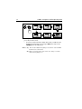
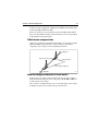
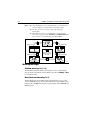
ST6001
Smartpilot
Controller
Operating Guide
Document number: 81215-1
Date: July 2003
ii
ST6001+ Smartpilot Controller Operating Guide
Autohelm, HSB (High Speed Bus), SailPilot, SeaTalk and SportPilot are registered trademarks of Raymarine Ltd.
Raymarine, AST (Advanced Steering Technology), AutoAdapt, AutoLearn,
AutoRelease, AutoSeastate, AutoTack, AutoTrim, FastTrim, GyroPlus,
RayGyro, RayPilot and WindTrim are trademarks of Raymarine Ltd.
Handbook contents © Raymarine Ltd. 2003.
Important Information
iii
Important Information
About the documentation provided
Welcome to Raymarine SmartPilot. The autopilot system that will steer your
boat to a heading automatically, accurately, reliably and comfortably.
SmartPilot documentation is arranged so that you can install, commission
and quickly use your SmartPilot, keeping to hand only the information
necessary.
•
•
•
•
Installation Sheets - One per element of the system, these easy to understand sheets guide you through the installation process. These can be discarded once the installation is complete.
SmartPilot Commissioning Guide - Describes how to connect, commission and configure the system.
Quick Start Guide - Once commissioned, use your Smart Pilot right
away with this handy guide to the main operations.
Operating Guide - This handbook. Contains a detailed description of
the SmartPilot’s features and functions.
Warranty
To register your new Raymarine product, please take a few minutes to fill out
the warranty card. It is important that you complete the owner information
and return the card to us to receive full warranty benefits.
Safety notices
WARNING: Calibration
We supply this product calibrated to default settings that should provide
initial stable performance for most boats. To ensure optimum performance
on your boat, you must complete the procedures in SmartPilot
Commissioning Guide before use.
WARNING: Navigation aid
Although we have designed this product to be accurate and reliable, many
factors can affect its performance. As a result, it should only be used as an aid
to navigation and should never replace common sense and navigational
judgement. Always maintain a permanent watch so you can respond to
situations as they develop.
iv
ST6001+ Smartpilot Controller Operating Guide
Your Raymarine SmartPilot will add a new dimension to your boating
enjoyment. However, it is the skipper’s responsibility to ensure the safety of
the boat at all times by following these basic rules:
•
•
•
•
•
•
Ensure that someone is present at the helm AT ALL TIMES, to take manual control in an emergency.
Make sure that all members of crew know how to disengage the autopilot.
Regularly check for other boats and any obstacles to navigation – no matter how clear the sea appears, a dangerous situation can develop rapidly.
Maintain an accurate record of the boat’s position by using either a navigation aid or visual bearings.
Maintain a continuous plot of your boat’s position on a current chart.
Ensure that the locked autopilot heading will steer the boat clear of all
obstacles. Make proper allowance for tidal set – the autopilot cannot.
Even when your autopilot is locked onto the desired track using a navigation aid, always maintain a log and make regular positional plots. Navigation signals can produce significant errors under some circumstances and
the autopilot will not be able to detect these errors.
EMC Conformance
All Raymarine equipment and accessories are designed to the best industry
standards for use in the recreational marine environment. Their design and
manufacture conforms to the appropriate Electromagnetic Compatibility
(EMC) standards, but correct installation is required to ensure that
performance is not compromised.
Handbook information
To the best of our knowledge, the information in this handbook was correct
when it went to press. However, Raymarine cannot accept liability for any
inaccuracies or omissions it may contain. In addition, our policy of
continuous product improvement may change specifications without notice.
As a result, Raymarine cannot accept liability for any differences between
the product and the handbook.
Contents
v
Contents
Important Information ....................................................................................... iii
About the documentation provided .........................................................iii
Warranty ..................................................................................................iii
Safety notices ...........................................................................................iii
EMC Conformance ................................................................................. iv
Handbook information ............................................................................ iv
Chapter 1: SmartPilot Operation .......................................................................1
1.1 Introduction ...................................................................................... 1
1.2 Using the control unit ....................................................................... 3
Start-up mode ................................................................................... 3
Keypad functions ............................................................................. 3
What does the display tell me? ......................................................... 4
1.3 Using the SmartPilot to steer your boat ............................................ 5
How do I automatically steer to a heading? ...................................... 5
How do I return to hand steering? ..................................................... 5
How do I change course in Auto mode? ........................................... 6
Can I dodge an obstacle and then resume course? ............................ 6
1.4 How do I adjust the performance of my SmartPilot? ....................... 7
Off Course warning .......................................................................... 9
1.5 Using the SmartPilot with sail boats ............................................... 10
1.6 Can I adjust the display lighting? ................................................... 11
Chapter 2: Advanced Operation .......................................................................13
2.1 How do I follow a route set on a Chartplotter? ............................... 13
How do I activate Track mode? ...................................................... 13
How do I leave Track mode? .......................................................... 14
What is Cross track error? .............................................................. 14
Tidal stream compensation ............................................................. 15
How do I dodge an obstacle in Track mode? .................................. 15
What happens when I arrive at a waypoint? ................................... 16
What happens when I get to the end of the route? ........................... 17
Safety in Track mode ...................................................................... 18
2.2 Using Wind Vane mode – sail boats ............................................... 18
What is Wind Vane mode? ............................................................. 18
How do I select Wind Vane mode? ................................................. 19
How do I leave Wind Vane mode? .................................................. 19
How do I adjust the locked wind angle ........................................... 19
How do I dodge an obstacle in Wind Vane mode? .......................... 20
What is a Wind Shift warning? ....................................................... 20
How do I use AutoTack in Wind Vane mode? ................................ 20
vi
ST6001+ Smartpilot Controller Operating Guide
Operating hints for Wind Vane mode ............................................. 21
2.3 How do I display boat data? ............................................................ 21
Warning messages .......................................................................... 22
2.4 User Calibration Options ................................................................ 23
How do I access User Calibration settings? .................................... 23
User Calibration pages ................................................................... 23
Chapter 3: Fault Finding & Maintenance .........................................................27
3.1 Fault finding ................................................................................... 27
SmartPilot alarm messages ............................................................ 28
3.2 General maintenance ...................................................................... 30
Routine checks ............................................................................... 30
Cleaning the display ....................................................................... 30
EMC advice .................................................................................... 30
Product support .............................................................................. 31
Specifications .......................................................................................................33
ST6001 control unit ................................................................................ 33
SmartPilot computer functions ............................................................... 33
Glossary .................................................................................................................34
Index ......................................................................................................................37
Chapter 1: SmartPilot Operation
1
Chapter 1: SmartPilot Operation
1.1 Introduction
1
60-
D54
The SmartPilot controller is a SeaTalk® compatible autopilot control unit. It
is designed as the main controller for the SmartPilot system.
The SmartPilot controller operates in the following modes:
•
•
•
•
Standby: SmartPilot off. You have manual control of the boat
Auto: The SmartPilot steers the boat to maintain a locked heading
Track: The SmartPilot steers the boat to maintain a track between two
waypoints created on a navigation aid
Wind Vane: The SmartPilot steers the boat to maintain a course relative
to a true or apparent wind angle
The SmartPilot controller also provides:
•
•
automatic tack (AutoTack) in Auto and Wind Vane modes
waypoint advance feature in Track mode
2
ST6001+ Smartpilot Controller Operating Guide
SmartPilot Functions
The functions provided with your SmartPilot system depend on whether the
SmartPilot computer contains an internal GyroPlus yaw sensor
:
S1G, S2G and S3G systems
(with GyroPlus)
Non-G systems
(without GyroPlus)
Internal GyroPlus yaw sensor provides
enhanced course keeping using AST
(Advanced Steering Technology)
Full basic functionality: uses Raymarine
steering algorithm without AST
Steering to true and apparent wind in
Wind Vane mode
Steering to true and apparent wind in
Wind Vane mode
Equipped with AutoLearn, Raymarine’s
self-learning calibration system
Extended systems
You can connect the SmartPilot controller to other Raymarine SeaTalk
equipment so it can send and receive SeaTalk data:
•
•
•
it can use waypoint information from a SeaTalk navigation instrument to
provide track control
it can use boat speed from a SeaTalk speed instrument to optimize trackkeeping performance
it can use wind information from a SeaTalk wind instrument for Wind
Vane steering
You can also use the SmartPilot with any navigator or wind instrument that
transmits National Marine Electronics Association (NMEA) 0183 data.
The SmartPilot control unit can display SeaTalk and NMEA instrument data
in a user-defined selection of data pages.
For further information on other connections to your system see SmartPilot
Commissioning Guide
Chapter 1: SmartPilot Operation
3
1.2 Using the control unit
Start-up mode
The SmartPilot always powers up in Standby mode with the display showing
the boat’s current compass heading.
Note: You can press standby at any time to return to manual steering.
Keypad functions
The SmartPilot is controlled using simple push-button operations, all of
which are confirmed with a short beep. In addition to the main single-key
functions, there are several dual key operations.
-1 plus -10
Press together
for AutoTack
to port
-1 plus +1
Press for Response level
Press for 1 second
for Rudder Gain
DISP
Press to display
data pages
Press for 1 second
for lamp control
STANDBY
Press for
Standby mode
Press for 2 seconds
to enter Calibration mode
Course change keys
Port 1˚ Starboard 1˚
Port 10˚ Starboard 10˚
+1 plus +10
Press together
for AutoTack
to starboard
TRACK
Press for Track
mode from Auto
(if a navigator is
connected)
Press to accept
waypoint advance
Press for 1 second
to skip waypoint
AUTO
Press for Auto mode
STANDBY plus AUTO
Press for Wind Vane mode
(if a wind vane is connected)
D5449-2
4
ST6001+ Smartpilot Controller Operating Guide
What does the display tell me?
The SmartPilot display screen provides the following information:
Variable text region (up to 9 characters/digits)
Heading indicators
Distance units:
• no units = kilometres
• nm = nautical miles
• SM = statute miles
Autopilot mode
indicators
Port and Starboard
direction-to-steer
indicators
Calibration mode
indicator (displayed on
calibration pages)
Rudder position indicator
D5457-2
The bar graph at the bottom of the screen indicates the current position of the
rudder, as measured by the rudder position sensor.
Chapter 1: SmartPilot Operation
5
1.3 Using the SmartPilot to steer your boat
How do I automatically steer to a heading?
1. Steady the boat on the required heading.
2. Press auto
The SmartPilot is now in AUTO mode and will steer to the chosen heading,
shown on the display. This mode is often known as “point-and-shoot”.
D3560-5
CAUTION:
Automatic course control makes it easier to sail a boat, but it is NOT a
substitute for good seamanship. ALWAYS maintain a permanent watch
by the helm.
How do I return to hand steering?
Press standby to disengage the SmartPilot:
•
in STANDBY mode, you have manual control of the boat and the display shows the boat’s current compass heading.
D3561-5
6
ST6001+ Smartpilot Controller Operating Guide
How do I change course in Auto mode?
In Auto mode, use the -1 and -10 (port) and +1 and +10 (starboard) keys to
change the locked heading in steps of 1° or 10°. For example: press -10 three
times for a 30° course change to port.
Port
Starboard
or
or
D3320-3
Can I dodge an obstacle and then resume course?
To avoid an obstacle when your boat is under autopilot control, you can
dodge the obstacle and then resume your previous course.
Obstacle
Original
course
Dodge
D3303-3P
1. Select a course change in the appropriate direction. For example, press 10 three times for a 30°dodge to port.
2. When safely clear of the obstacle, reverse the previous course change (for
example, press +10 three times).
Chapter 1: SmartPilot Operation
7
1.4 How do I adjust the performance of my
SmartPilot?
The principal method of adjusting the performance of SmartPilot systems is
by changing the response level. This is the only user adjustment you should
need to make to your SmartPilot on a regular basis.
The response level controls the relationship between the SmartPilot’s course
keeping accuracy and the amount of helm/drive activity. When you turn on
your SmartPilot it will always be at the default level. (This level can be
adjusted in User Calibration see page 23)
When you require extra tight course keeping (e.g. for pilotage in confined
and sheltered waters), increase the setting. If you want to minimize drive
activity and conserve battery power, decrease the setting.
You can make temporary adjustments to the response level when using your
SmartPilot on a day-to-day basis. By doing this you can match performance
to conditions as they occur.
Note: You will lose these temporary changes to response level whenever the
system is powered off. You can make permanent adjustments in User Calibration (See page 23). This determines the default power-up response level.
Adjusting performance – S1G, S2G and S3G systems
S1G, S2G and S3G systems systems have 9 levels of response:
•
•
•
level 9 to 7 give the tightest course keeping and greatest rudder activity
(and power consumption). This can lead to a rough passage in open
waters as the SmartPilot may ‘fight’ the sea.
levels 6 to 4 should give good course keeping with crisp, well controlled
turns under normal operating conditions
level 3 to 1 minimizes the amount of pilot activity. This conserves
power, but may compromise short-term course-keeping accuracy
With these points in mind, you should use the following procedure to make
temporary adjustments to the response level when required:
1. Display the RESPONSE screen by pressing the -1 and +1 keys together
momentarily.
8
ST6001+ Smartpilot Controller Operating Guide
Decrease
response
Increase
response
D5452-2
Note: The RESPONSE screen is set as a default data page (see SmartPilot
Commissioning Guide) so you can also access it by pressing disp and then
scrolling through the data pages.
2. Press -1 or +1 to change the response level.
3. Press disp or wait for 5 seconds to return to the previous display.
Adjusting performance – Non-G systems
Non-G SmartPilot systems have three different response levels:
•
•
•
Response Level 1: AutoSeastate on (Automatic deadband)
The SmartPilot will gradually ignore repetitive boat movements and
only react to true variations in course. This provides the best compromise between power consumption and course keeping accuracy
Response Level 2: AutoSeastate off (Minimum deadband)
This setting provides tighter course keeping but will lead to increased
power consumption and drive unit activity
Response Level 3: AutoSeastate off + yaw damping
This setting provides the tightest possible course keeping by introducing
counter rudder yaw damping You can adjust the counter rudder setting in
Dealer Calibration (see SmartPilot Commissioning Guide)
To make a temporary change to the response setting:
1. Display the RESPONSE screen by pressing the -1 and +1 keys together
2. Press -1 or +1 to change the response between levels 1 to 3.
3. Press disp or wait for 5 seconds to return to the previous display.
Note: You will lose these temporary changes to response level whenever the
system is powered off. You can make permanent adjustments in User Calibration (see page 23).
Chapter 1: SmartPilot Operation
9
Off Course warning
= deviation to port
= deviation to starboard
D3315-4
The SmartPilot warns you when you have been off course from the locked
heading for longer than 20 seconds. It shows whether the deviation is to port
or starboard.
Note: The default off course angle is set at 20º. You can adjust this angle in
Dealer Calibration (see SmartPilot Commissioning Guide).
1. To cancel the off course warning, press standby to return to manual
steering.
2. Check whether your boat is carrying too much sail, or whether the sails
are badly balanced. You can usually significantly improve course keeping by improving the sail balance.
Note: The SmartPilot also clears the warning if the heading recovers or if
you change course.
10
ST6001+ Smartpilot Controller Operating Guide
1.5 Using the SmartPilot with sail boats
Using the SmartPilot to automatically tack (AutoTack)
The SmartPilot has a built in automatic tack facility (AutoTack) that turns the
boat through 100° in the required direction. If you have set the vessel type to
SAIL BOAT, you can adjust the default AutoTack angle in User Calibration (see
page 23).
•
•
to AutoTack to port: press the -1 and -10 keys together
to AutoTack to starboard: press the +1 and +10 keys together
CAUTION:
When making major course changes, the trim on the boat may change
substantially. Due to this, the SmartPilot may take some time to settle
accurately onto the new course.
AutoTack - Port
AutoTack - Starboard
Wind
Wind
AutoTack
angle
AutoTack
angle
D5399-1
How do I prevent accidental gybes?
Note: For the gybe inhibit feature to work, the SmartPilot needs suitable
wind information (see page 24).
The gybe inhibit feature stops the boat from performing an AutoTack away
from the wind – this will prevent accidental gybes. This feature can be disabled if required.
With gybe inhibit on:
• you will be able to perform an AutoTack into the wind
• to prevent accidental gybes, the autopilot will prevent the boat from
performing an AutoTack away from the wind
Chapter 1: SmartPilot Operation
11
With gybe inhibit off:
• you can perform an AutoTack into or away from the wind.
Note: Gybe inhibit is switched on as a default but can be disabled in User
Calibration (see page 23).
Gusty conditions
In gusty conditions, the course may tend to wander slightly, particularly if the
sails are badly balanced. If you take the following precautions, the SmartPilot will be able to maintain competent control even in gale force conditions:
•
•
You can improve course keeping by improving the sail balance:
• do not allow the boat to heel over excessively
• ease the mainsheet traveller to leeward to reduce heeling and weather
helm
• if necessary, reef the mainsail a little early
In very strong winds and large seas, you should avoid sailing with the
wind dead astern:
• ideally, bring the wind at least 30° away from a dead run
• in severe conditions, you may also need to remove the mainsail and
sail under headsail only
1.6 Can I adjust the display lighting?
You can adjust the display and keypad lighting by:
1. Pressing disp for 1 second from any mode to access the LAMP screen and
turn on the lights.
2. Press the disp key to cycle through the possible illumination settings:
LAMP 3 (the brightest setting), LAMP 2, LAMP 1, OFF, LAMP 1, LAMP 2,
LAMP 3 and so on:
• as you change the setting, the illumination on any other SeaTalk
instruments or control units will also change
12
ST6001+ Smartpilot Controller Operating Guide
.
1 second
D3313-4
3. The display automatically returns to the previous mode if you do not
press a key for 10 seconds:
• if you press another mode key within 10 seconds you will select the
mode assigned to that key (for example: auto selects Auto mode,
standby selects Standby mode)
Notes: (1) You can also adjust the lighting level from any other SeaTalk
instrument or control unit.
(2) When you switch off the unit you lose any changes you have
made to the lighting level.
Chapter 2: Advanced Operation
13
Chapter 2: Advanced Operation
2.1 How do I follow a route set on a Chartplotter?
By using TRACK mode, the SmartPilot can maintain a route between
waypoints created on a navigation system. It makes any course changes
necessary to keep your boat on course, automatically compensating for tidal
streams and leeway.
Track mode is only available if you have connected the SmartPilot to a suitable navigation system providing SeaTalk or NMEA information. (See
SmartPilot Commissioning Guide for connection details)
Your SmartPilot system can receive route information from:
•
•
a SeaTalk navigation instrument or chartplotter
a navigation system transmitting data in NMEA 0183 format.
How do I activate Track mode?
CAUTION:
When you enter Track mode, the SmartPilot will bring the boat onto the
track in a controlled way. The closer the boat is to the correct heading
and track, the quicker it will settle the boat onto the new course. To avoid
an unexpected turn, approximately align the boat with the required
track before entering Track mode.
Starting with the SmartPilot in AUTO mode and your chartplotter following a
route.
1. Press track to enter Track mode.
2. Wait for the warning to sound.
The display will show the bearing to the next planned waypoint and the
direction in which the boat will turn to reach this waypoint.
3. If it is safe for the boat to turn onto the new course, press the track key:
• the SmartPilot will turn the boat onto the new course.
• the display shows the heading required to achieve the required track
Note: The closer the boat is to the correct heading and track when you press
track, the quicker the SmartPilot will bring the boat onto the new course. If
the boat is more than 0.3 nm from the track, the Large Cross Track Error
warning will sound (see page 14).
14
ST6001+ Smartpilot Controller Operating Guide
Automatic track acquisition
Waypoint at 270˚
Waypoint at 270˚
Current
heading
From auto mode, press track to enter Track mode . . .
. . . then press track again to turn boat to waypoint.
D5414-3
Previous
heading
How do I leave Track mode?
You can leave Track mode at any time by:
•
•
pressing auto to return to Auto mode
pressing standby to steer manually in Standby mode
What is Cross track error?
Cross track error (XTE)
more than 0.3 nm
e
out
ned
n
Pla
te
rou
Waypoint 1
Cross track error (XTE) is the distance between the current position and a
planned route. The SmartPilot receives the cross track error information
D5415-3
al r
u
Act
Waypoint 2
Chapter 2: Advanced Operation
15
from the navigation equipment, and displays the XTE in nautical miles (nm),
statute miles (SM) or kilometres (km).
If the cross track error is greater than 0.3 nm, the SmartPilot will sound the
Large Cross Track Error warning and show whether you are to the port (Pt) or
starboard (Stb) of the planned track.
Tidal stream compensation
Under most conditions, the SmartPilot will hold the selected track to within
±0.05 nm (300 ft) or better. It takes account of the boat’s speed when
computing course changes to ensure optimum performance.
Waypoint 2
Boat's speed over ground
Tidal component
Boat's speed through water
Waypoint 1
D3261-3
How do I dodge an obstacle in Track mode?
In Track mode you still have full control from the keypad. You can make a
dodge maneuver by using the course change keys (-1, +1, -10 or +10) to select the desired course change.
After you have avoided the hazard, you can cancel the dodge course change
by making an equal course change in the opposite direction.
16
ST6001+ Smartpilot Controller Operating Guide
What happens when I arrive at a waypoint?
As the boat arrives at the target waypoint the chartplotter will select the next
target waypoint and transmit this to the SmartPilot. It will then detect the new
target waypoint name, sound a Waypoint Advance warning and display the
Waypoint Advance (NEXT WPT) screen. This shows the new bearing to the
next waypoint and the direction the boat will turn to acquire the new track.
Waypoint arrival and advance
Next target
Waypoint at 270˚
Waypoint arrival
Old target
Waypoint
Waypoint advance
D5416-3
Target
Waypoint
New target
waypoint at 270˚
How do I get to the next waypoint in a route?
When the Waypoint Advance warning sounds, the SmartPilot suspends
Track mode and maintains the current boat heading.To advance to the next
waypoint:
1. Check that it is safe to turn onto the new track.
2. Press the track key. This will cancel the Waypoint Advance warning and
turn the boat towards the next waypoint.
Note: If you do not press track to accept the Waypoint Advance, the SmartPilot will maintain the current heading and continue sounding the warning.
How do I skip a waypoint? (SeaTalk chartplotters)
If you want to advance to the next waypoint before you have arrived at the
target waypoint, you can skip a waypoint by pressing track for 1 second. The
display will then show the Waypoint Advance screen for the next waypoint.
Check it is safe to turn, then press track to turn the boat towards the next
waypoint.
Chapter 2: Advanced Operation
17
WARNING:
Skipping a waypoint will take you straight to the next waypoint. Check
your navigation before making the turn.
What is the Waypoint Advance warning?
The SmartPilot activates the Waypoint Advance warning (NEXT WPT?) in
Track mode whenever the target waypoint name changes. This occurs when:
•
•
•
•
you select automatic acquisition by pressing track from Auto
you request waypoint advance by pressing track for 1 second in Track
mode (with SeaTalk navigators only)
the boat arrives at the target and the navigator accepts the next waypoint
you activate the Man Overboard (MOB) function (see page 22)
When the warning sounds, the SmartPilot continues on its current heading
but displays:
•
•
the bearing to the next waypoint
the direction the boat will turn to take up that bearing
How do I respond to a Waypoint Advance warning?
To respond to a Waypoint Advance warning:
•
•
check that it is safe to turn onto the new track, then press track to accept
the waypoint advance
alternatively, you can cancel the warning without accepting the waypoint
advance by pressing:
• auto to continue on the same heading, or
• standby to return to manual control
What happens when I get to the end of the route?
The SmartPilot displays the ROUTE COMPLETED warning when you have
reached the last waypoint on a route in Track mode.
•
•
press auto to continue on the same heading
or press standby to return to manual control
18
ST6001+ Smartpilot Controller Operating Guide
Safety in Track mode
CAUTION:
Track mode provides accurate track keeping even in complex
navigational situations. However, it is still the skipper’s responsibility to
ensure the safety of their boat at all times through careful navigation and
frequent position checks. Track mode assists precise navigation and
removes the tasks of compensating for wind and tidal drift. However,
you MUST still maintain an accurate log with regular plots.
2.2 Using Wind Vane mode – sail boats
Note: You can only select Wind Vane mode if the SmartPilot is receiving
suitable SeaTalk or NMEA wind direction information.
What is Wind Vane mode?
When the SmartPilot is in Wind Vane mode it uses the fluxgate compass as
the primary heading reference. As changes in the true or apparent wind angle
occur, it adjusts the locked heading to maintain the original wind angle.
Wind information
To use Wind Vane mode, the SmartPilot must receive wind information from
one of the following sources:
•
•
•
SeaTalk wind instrument connected to the autopilot via SeaTalk
NMEA wind instrument
Raymarine pushpit wind vane connected via a SeaTalk interface
True and apparent wind
SmartPilots can maintain a course relative to either an apparent or true wind
angle in Wind Vane mode
The default setting is apparent wind. If required, you can change this to true
wind in User Calibration (see page 24).
WindTrim
In Wind Vane mode the SmartPilot uses WindTrim to eliminate the effects of
turbulence and short term wind variations. This provides smooth and precise
performance with minimal power consumption. You can adjust the wind
response (WindTrim) level in User Calibration (see page 24) to control how
quickly the SmartPilot responds to changes in the wind direction. Higher
Chapter 2: Advanced Operation
19
wind trim settings will result in a pilot that is more responsive to wind
changes.
How do I select Wind Vane mode?
You can select Wind Vane mode from either Standby or Auto mode:
1. Steady the boat onto the required wind angle.
2. Press standby and auto together to select Wind Vane mode and lock the
current wind angle:
• the display shows the locked heading (e.g. 128°) and the wind angle
(e.g.WIND 145P indicates an wind angle of 145° to port)
• if the SmartPilot does not enter Wind Vane mode, it is not receiving
wind data - check the instrument and connections
+
D3565-5
3. In Wind Vane mode, the SmartPilot will then adjust the boat’s heading to
maintain the locked wind angle.
How do I leave Wind Vane mode?
You can leave Wind Vane mode by:
•
•
pressing auto to return to Auto mode
pressing standby to return to manual control
How do I adjust the locked wind angle
You can adjust the locked wind angle by using the -1, +1, -10 and +10 keys to
change course. For example, to bear away by 10° when the boat is on a
starboard tack:
•
•
press -10 to turn the boat 10° to port – the locked wind angle and locked
heading will both change by 10°
the autopilot will then adjust the locked heading as required to maintain
the new wind angle
20
ST6001+ Smartpilot Controller Operating Guide
Note: Because turning the boat affects the relationship between the true and
apparent wind angles, you should only use this method to make minor adjustments to the wind angle. For major changes, return to Standby mode,
steer onto the new heading, then reselect Wind Vane mode.
How do I dodge an obstacle in Wind Vane mode?
In Wind Vane mode you still have full control from the keypad. You can
make a dodge maneuver by using the course change keys (-1, +1, -10 or +10)
to select the desired course change.
After you have avoided the hazard, you can cancel the dodge course change
by making an equal course change in the opposite direction.
What is a Wind Shift warning?
If the autopilot detects a wind shift of more than 15° it will sound the wind
shift warning and display the WIND SHIFT message:
•
•
To cancel the warning, and retain the existing wind angle and new heading, press standby and auto together.
Alternatively, to cancel the warning and return to the previous heading:
• adjust the locked wind angle using the -1, +1, -10 and +10 keys.
• press standby to return to hand steering, steer onto the required
heading, and press standby and auto together to return to Wind
Vane mode with the new wind angle
How do I use AutoTack in Wind Vane mode?
Note: If you use the AutoTack function in Wind Vane mode, make sure the
wind vane has been centered accurately.
The SmartPilot has a built in automatic tack facility (AutoTack) that turns the
boat through 100° in the required direction:
•
•
to AutoTack to port: press the -1 and -10 keys together
to AutoTack to starboard: press the +1 and +10 keys together
Chapter 2: Advanced Operation
21
AutoTack - Port
AutoTack - Starboard
Wind
Wind
AutoTack
angle
AutoTack
angle
D5399-2
Note: If you have set the vessel type to SAIL BOAT, you can adjust the default
AutoTack angle in User Calibration (see page 23).
When you AutoTack in Wind Vane mode, the boat turns through the
AutoTack angle. The SmartPilot will then trim the heading to mirror the
locked wind angle from the previous tack.
Operating hints for Wind Vane mode
•
•
•
•
Always trim your sails carefully to minimize the amount of standing
helm.
Reef the headsail and mainsail a little early rather than too late.
In Wind Vane mode the SmartPilot will react to long-term wind shifts, but
will not correct for short-term changes such as gusts.
In gusty and unsteady inshore conditions, it is best to sail a few degrees
further off the wind so that changes in wind direction can be tolerated.
2.3 How do I display boat data?
Use the disp key to show ‘data pages’ of SeaTalk or NMEA data:
1. Press disp to access the first data page, and press it again to cycle through
each data page in turn:
• when you cycle past the last data page, the display returns to the current SmartPilot mode screen (for example, AUTO)
• 4 data pages are set in the factory as a default (see diagram): within
User setup you can select up to 7 pages and control the information
they display (see page 23)
22
ST6001+ Smartpilot Controller Operating Guide
Notes: (1) If the SmartPilot system cannot obtain the required information, the data page will show dashes instead of a value.
(2) The direction-to-steer arrows relate to the data page
information.
(3) Most data pages show repeated data so you cannot adjust
them: the exceptions are the RESPONSE and RUDDER GAIN data
pages, which you can adjust using the -1 and +1 keys
Default data pages
Data page 4
Data page 1
Autopilot mode
Data page 3
Press for 1 sec to
return to previous
data page
Data page 2
D5455-2
Warning messages
Shallow warning (SHALLOW)
The SmartPilot shows the Shallow warning if it receives a shallow depth
message from an instrument on the SeaTalk system. Press standby or disp
to cancel the warning.
Man Overboard warning (MOB)
The SmartPilot activates the Man Overboard warning if it receives a man
overboard (MOB) message from another instrument on the SeaTalk system.
It displays the text MOB instead of the waypoint number for the XTE, DTW and
BTW data pages.
Chapter 2: Advanced Operation
23
2.4 User Calibration Options
The calibration information in this handbook relates to only those settings
that can be adjusted during normal operation (USER CAL). For information on
all available calibration settings, see SmartPilot Commissioning Guide.
Note: Many of the settings are sailboat specific and will only be displayed if
your vessel type is set to SAILBOAT
How do I access User Calibration settings?
You can only access the calibration mode from Standby mode:
1. With the SmartPilot in Standby mode, press and hold the standby key
for 2 seconds. The display will change to show DISPLAY CAL.
2. Press the disp key once, the display will now show USER CAL.
3. Press auto to enter User Calibration.
The first page of User Calibration will now be displayed.
4. To access other User Calibration pages, press disp to scroll down
through the items within that grouping:
5. When you reach an item you wish to adjust, use the -1, +1, -10 and +10
keys (as appropriate) to change the value.
6. When you have made all the changes you want to make, press and hold
standby for two seconds to exit calibration mode and save changes.
User Calibration pages
AutoTack angle (SAILBOAT only)
The AutoTack angle is the angle through which the boat will turn when you
select an automatic tack.
Screen Text
Options
AUTO TACK
40° to 125° in 1° steps
24
ST6001+ Smartpilot Controller Operating Guide
Gybe inhibit (SAILBOAT only)
With gybe inhibit on:
•
•
you will be able to perform an AutoTack into the wind
to prevent accidental gybes, the SmartPilot will prevent the boat from
performing an AutoTack away from the wind
With gybe inhibit off, you can perform an AutoTack into or away from the
wind.
Screen Text
Options
GYBE STOP
ON (Default) = Gybe inhibit on (gybes prevented)
OFF = Gybe inhibit off (gybes permitted)
Wind selection (SAILBOAT only)
This screen determines whether the boat steers to apparent or true wind in
Wind Vane mode.
Options
WIND APP (Default)
SmartPilot steers to apparent wind angle
WIND TRUE
SmartPilot steers to true wind angle
WindTrim (SAILBOAT only)
WindTrim controls how quickly the SmartPilot responds to changes in the
wind direction. Higher wind trim settings will result in a system that is more
responsive to wind changes.
Screen Text
Options
WIND TRIM
Range = 1 to 9
1 to 3 - Least responsive to wind changes (less system activity)
4 to 6 - Moderate response to wind changes
7 to 9 - Most responsive to wind changes (more system activity)
Chapter 2: Advanced Operation
25
Response level
This sets the default SmartPilot response level setting. The response level
controls the relationship between course keeping accuracy and the amount of
helm/drive activity. You can make temporary changes to response during
normal operation (see Operation Guide).
S1G, S2G and S3G systems
Screen Text
Options
RESPONSE
Range = 1 to 9
levels 9 to 7 gives the tightest course keeping and greatest
rudder activity (and power consumption). This can lead to a
rough passage in open waters as the SmartPilot may ‘fight’
the sea.
levels 6to 4 should give good course keeping with crisp,
well controlled turns under normal operating conditions
levels 3 to 1 minimizes the amount of pilot activity. This conserves power, but may compromise short-term course-keeping accuracy
Non-G SmartPilot systems
Screen Text
Options
RESPONSE 1
AutoSeastate on (Automatic deadband)
The SmartPilot will gradually ignore repetitive boat movements and only react to true variations in course. This provides
the best compromise between power consumption and
course keeping accuracy
RESPONSE 2
AutoSeastate off (minimum deadband)
This setting provides tighter course keeping but will lead to
increased power consumption and drive unit activity
RESPONSE 3
AutoSeastate off + counter rudder yaw damping
This setting provides the tightest possible course keeping by
introducing counter rudder yaw damping
26
ST6001+ Smartpilot Controller Operating Guide
Chapter 3: Fault Finding & Maintenance
27
Chapter 3: Fault Finding & Maintenance
All Raymarine products are designed to provide many years of trouble-free
operation. We also put them through comprehensive testing and quality
assurance procedures before shipping.
This chapter provides information about identifying problems, interpreting
alarm messages, maintaining your SmartPilot and obtaining product
support.
If a fault occurs with your SmartPilot, use the fault finding tables in this
section to help identify the problem and provide a solution.If you cannot
resolve the problem yourself, refer to the product support information.
3.1 Fault finding
SYMPTOM
POSSIBLE CAUSE and SOLUTION
Display is blank
No power – check the power and SeaTalk fuses on
course computer, then check main fuse/circuit breaker.
Data page display shows stationary dashes
The control unit is not receiving necessary data from
other instruments – check cabling.
Display shows rotating dashes
Compass calibration in progress (see SmartPilot Commissioning Guide).
Displayed compass heading
does not agree with the boat’s
compass
You have not calibrated the compass. Carry out the deviation and alignment procedures (see SmartPilot Commissioning Guide).
No display bar on the display
Rudder bar switched off in Display Calibration – select
RUDD BAR or STEER BAR
Rudder bar display moves in
opposite direction to rudder
Reverse the red and green rudder position sensor connections at the course computer
Boat turns slowly and takes a
long time to come onto course
Rudder gain too low. Complete AutoLearn or increase
gain setting.
Boat overshoots when turning
onto a new course
Rudder gain too high. Complete AutoLearn or decrease
gain setting.
The SmartPilot ‘hunts’ when
trying to position the rudder
Adjust the RUDD DAMP setting (see SmartPilot Commissioning Guide). Increase the damping one level at a time
until the autopilot stops hunting, and always use the
lowest acceptable value
28
ST6001+ Smartpilot Controller Operating Guide
SYMPTOM
POSSIBLE CAUSE and SOLUTION
The SmartPilot appears to be
Northerly/Southerly heading correction (AutoAdapt) is
unstable on Northerly headings not set up (see SmartPilot Commissioning Guide). [Does
in the Northern hemisphere (or not apply to S1G, S2G and S3G systems.]
Southerly headings in the
Southern hemisphere)
You cannot enter Seatrial Calibration
Seatrial calibration lock is on – turn off the calibration
protection feature in Dealer Calibration (see SmartPilot
Commissioning Guide).
The SmartPilot will not ‘talk’ to
other SeaTalk instruments
Cabling problem – make sure all the cables are connected properly.
Position information not
received
Navigator not transmitting the correct position data.
The SmartPilot will not auto
advance to the next waypoint
No bearing to waypoint information received from the
navigator.
Non-Raymarine 24V autopilots
clutch slipping
Check that the clutch fuse is in the correct position. E.g.
24 V position for 24 V clutches.
When holding a constant course The Autopilot is connected to a Raymarine Pathfinder
in STANDBY mode, the heading unit with the “Bridge NMEA Heading” option switched
continuously changes
on. Disable this feature on the Pathfinder unit.
SmartPilot alarm messages
When the SmartPilot detects a fault or failure on the system, it will activate
one of the alarm messages listed in the following table.
•
•
Unless otherwise stated, you should respond to the alarm by pressing
standby to clear the alarm and return to manual control, before you
attempt to resolve the problem.
In some situations, the SmartPilot will raise more than one alarm. When
you have dealt with the first alarm, it will display the next alarm.
ALARM MESSAGE
POSSIBLE CAUSE and SOLUTION
AUTO RELEASE
Possible fault with rudder position sensor – check connections.
OR
Stern (I/O) drives only – you have taken manual control of steering with
AutoRelease on. The alarm cancels automatically after 10 seconds.
CURRENT LIMIT
Serious drive failure – the drive is taking too much current due to shortcircuit or jamming. Check the drive unit.
Chapter 3: Fault Finding & Maintenance
29
ALARM MESSAGE
POSSIBLE CAUSE and SOLUTION
DRIVESTOP
The autopilot is unable to turn the rudder (this occurs if the weather
load on helm is too high, or if the rudder position sensor has passed
beyond the preset rudder limits or rudder end-stops).
Check drive and rudder position sensor.
LOW BATT
Supply voltage has dropped below acceptable limits.
To respond to a Low Battery alarm:
• press standby to clear the alarm and return to hand steering
• start the engine to recharge the battery
LRN FAIL 1, 2 or 4
AutoLearn not completed successfully.
Failure codes:
1 = AutoLearn has not been carried out (default setting)
2 = AutoLearn failed, usually due to manual interruption
4 = AutoLearn failed, probably due to drive or compass failure
Repeat the AutoLearn procedure.
MOT POW SWAPPED
Motor cables are connected to power terminals (and power cables are
connected to motor terminals) at course computer. Turn off power and
swap over connections.
NO DATA
Caused by any of the following situations:
• the compass is not connected
• the autopilot is in Wind Vane mode and it has not received wind
angle data for 30 seconds
• the autopilot is in Track mode and:
• the autopilot is not receiving SeaTalk navigation data, or
• the position sensor (GPS, Loran, Decca) is receiving a low strength
signal – this will clear when the signal improves
Check connections to the compass, wind instrument and navigator.
Note: The autopilot stops adjusting the heading as soon as it loses
data.
NO PILOT
The controller is not receiving data from the SmartPilot computer.
Check connections and check course computer is switched on.
RG FAIL
GyroPlus yaw sensor has failed:
• If you have a S1G, S2G or S3G course computer with internal
GyroPlus sensor – call a Raymarine service agent.
• If you have a Non-Gscourse computer with external GyroPlus yaw
sensor – check the sensor and connections, then call a Raymarine service agent.
SEATALK and FAIL 1 or 2
SeaTalk data problem on one of the SeaTalk lines – check connections.
STLK FAIL
The control unit cannot transmit data to the SeaTalk system. Make sure
all SeaTalk cables are connected properly.
30
ST6001+ Smartpilot Controller Operating Guide
3.2 General maintenance
Routine checks
CAUTION:
The SmartPilot computer and controller do not contain any user
serviceable parts. It should be serviced only by authorized Raymarine
service technician.
The SmartPilot computer does NOT contain user-serviceable parts. If you
remove the main cover you will invalidate the warranty. The controller is also
a sealed unit. As a result, user maintenance is limited to the following checks
•
•
make sure all cable connectors are firmly attached
examine for signs of wear or damage – replace any damaged cables
Note: Do not use chemical or abrasive materials to clean the SmartPilot
computer. If the case is dirty, wipe it with a clean, damp cloth.
Cleaning the display
CAUTION:
Take care when cleaning the display. Avoid wiping the display screen
with a dry cloth as this could scratch the screen coating. If necessary,
only use a mild detergent.
•
•
Never use chemical or abrasive materials to clean the controller. If it is
dirty, wipe it with a clean, damp cloth.
In certain conditions, condensation may appear inside the display screen.
This will not harm the unit, and you can clear it by switching on the illumination for a short time.
EMC advice
•
•
•
When powered up, all electrical equipment produces electromagnetic
fields. These can cause adjacent pieces of electrical equipment to interact
with one another, with a consequent adverse effect on operation.
To minimize these effects and enable you to get the best possible performance from your Raymarine equipment, guidelines are given in the
installation instructions, to enable you to ensure minimum interaction
between different items of equipment, i.e. ensure optimum Electromagnetic Compatibility (EMC).
Always report any EMC-related problems to your nearest Raymarine
dealer. We use such information to improve our quality standards.
Chapter 3: Fault Finding & Maintenance
•
31
In some installations, it may not be possible to prevent the equipment
from being affected by external influences. In general this will not damage the equipment but it can lead to spurious resetting action, or momentarily may result in faulty operation.
Product support
Raymarine products are supported by a worldwide network of distributors
and Authorized Service Representatives. If you encounter any difficulties
with this product, please contact either your national distributor, service
representative, or the Raymarine Technical Services Call Center. Refer to the
back cover or the Worldwide Distributor List for contact details.
Before you consider returning the autopilot, make sure that the power supply
cable is sound and that all connections are tight and free from corrosion. If the
connections are secure, refer to the Fault Finding section in this chapter.
If you cannot trace or rectify the fault, contact your nearest Raymarine dealer
or Service Center, specifying:
•
•
the SmartPilot controller and SmartPilot computer serial numbers:
• the controller serial number is printed on its rear cover
• the computer serial number is printed under its connector cover
the controller and computer software version numbers
The following illustration shows how to display the software information:
•
•
•
press and hold standby for 4 seconds:
• after 2 seconds you will see the DISPLAY CAL screen
• then after another 2 seconds you see controller software version
press disp to display the computer software version
press disp again to display the total number of hours the SmartPilot has
been used in Auto mode.
32
ST6001+ Smartpilot Controller Operating Guide
Software information
4 seconds
1 second
Control unit
software version
Time autopilot
used in Auto
1 second
Course computer
software version
1 second
D5493-2
Product details table
For future reference, you may want to use this table to record serial and
software information for your SmartPilot:
Serial Number
Software Version
SmartPilot Controller
SmartPilot Computer
Hours Used
hours
Specifications
33
Specifications
ST6001 control unit
Nominal supply voltage:
12 V DC via SeaTalk
Operating voltage range:
10 V to 15 V DC
Current consumption (in Standby mode)
60 mA (less than 200 mA with full lighting)
Operating temperature:
0 °C to +70 °C (32 °F to 158 °F)
Water protection:
waterproof to CFR46
Overall dimensions:
width
height
depth
110 mm (4.33 in)
115 mm (4.53 in)
41 mm (1.62 in)
Keypad:
8 button illuminated keypad
Liquid Crystal Display (LCD):
shows heading, locked course and navigational data, and up
to 7 data pages
LCD illumination:
3 brightness levels + off
Input connections:
SeaTalk (x2) and NMEA 0183
Output connections:
SeaTalk (x2)
CE approvals:
conforms to: 89/336/EC (EMC), EN60945:1997
SmartPilot computer functions
SmartPilot computer
Controller
ST6001
S1G, S2G and S3G systems
Non-G systems
• Internal GyroPlus yaw sensor
• Enhanced course keeping using AST
• FastTrim
• Full access to AutoLearn, providing
automatic steering calibration
• Improved track-keeping
• Steers to true and apparent wind in Wind
Vane mode
• Improved calibration access
• Full basic functionality
• Improved track-keeping
• Steers to true and apparent wind in Wind
Vane mode
• Improved calibration access, but without
AutoLearn
• Uses Raymarine steering algorithm
without AST
• No FastTrim
34
ST6001+ Smartpilot Controller Operating Guide
Glossary
Term
Meaning
AST
Advanced Steering Technology (AST) is Raymarine’s unique advanced steering
algorithm. It uses inputs from a wide variety of sensors to tune the autopilot’s operation to provide superior control of the boat in any condition.
AutoLearn
Self-learning calibration feature available on S1G, S2G and S3G autopilot systems.
AutoTrim
The AutoTrim setting determines the rate at which the autopilot applies ‘standing
helm’ to correct for trim changes caused by varying wind loads on the sails or superstructure.
AWG
American Wire Gauge
CE
Marked on Raymarine products that comply with defined European Community
standards
counter rudder
Counter rudder is the amount of rudder the autopilot applies to try to prevent the
boat from yawing off course. Higher counter rudder settings result in more rudder
being applied.
CR pump
Constant Running hydraulic pump
DC
Direct current
EMC
(Electromagnetic
Compatibility)
When powered up, all electrical equipment produces electromagnetic fields. These
can cause adjacent pieces of electrical equipment to interact with one another, and
this can degrade their performance. By following the EMC guidelines in this handbook, you can minimize these effects by ensuring optimum Electromagnetic Compatibility (EMC) between equipment.
Fluxgate
Standard Raymarine compass supplied with course computer core pack
GPS
Global Positioning System
GyroPlus
Raymarine’s GyroPlus yaw sensor that measures the boat’s rate of turn. It is built
into the S1G, S2G and S3G course computers.
I/O drive
Inboard/Outboard or stern drive
MOB
Man overboard
nm
Nautical mile
NMEA
The NMEA (National Maritime Electronics Association) protocol is an internationally accepted serial communication interface standard for sharing data between
electronic equipment. Raymarine products can share information with nonSeaTalk equipment using the NMEA 0183 protocol.
Glossary
35
Term
Meaning
response
The autopilot response level controls the relationship between course keeping
accuracy and the amount of helm/drive activity.
rudder gain
Rudder gain is a measure of how much helm the autopilot will apply to correct
course errors. The higher the setting the more rudder will be applied.
SeaTalk
SeaTalk is Raymarine’s proprietary communication system. It links the products to
provide a single, integrated system sharing power and data.
SeaTalk bus
This refers to the continuous SeaTalk system connecting together a series of Raymarine units.
SM
Statute (land) mile
VHF
Very High Frequency (radio)
WindTrim
WindTrim (wind response) controls how quickly the autopilot responds to changes
in the wind direction. Higher wind trim settings will result in a pilot that is more
responsive to wind changes.
XTE
Cross track error
Yaw
The boat’s rate of turn (°/sec)
36
ST6001+ Smartpilot Controller Operating Guide
Index
37
Index
A
F
Alarms 28
AUTO RELEASE 28
CURRENT LIMIT 28
DRIVE STOPPED 29
LARGE XTE 14
LOW BATT 29
LRN FAIL 29
MOB 22
MOT POW SWAPPED 29
NEXT WPT 17
NO DATA 29
NO PILOT 29
OFF COURSE 9
RG FAIL 29
SEATALK FAIL 1 or 2 29
SHALLOW 22
WINDSHIFT 20
Auto mode 5
AutoTack 9
Changing course 6
Dodging obstacles 6
Off course warning 9
AutoRelease
Alarm 28
AutoTack 9, 23
in wind vane mode 20
Fault finding 27
Following a route 13
C
P
Controller
Specifications 33
Course changes 6
Cross track error
Explanation 14
LARGE XTE warning 14
Current limit alarm 28
Performance 7
Preventing gybes 9
Product support 31
D
S
Data pages 21
Dodging obstacles
Auto mode 6
Drive stopped alarm 29
G
Glossary 34-35
Gybe inhibit 9, 24
GyroPlus fail alarm 29
K
Keypad functions 3
L
Learn fail alarm 29
Low battery alarm 29
M
Maintenance 30
Man Overboard alarm 22
Motor/Power swapped alarm 29
N
Next WPT warning 17
No data alarm 29
No pilot alarm 29
O
Off course warning
Description 9
R
Response level 25
RG fail alarm 29
Route completed 17
Safety notices iii
Track mode 18
Sailboats
AutoTack 9
38
Preventing gybes 9
SeaTalk
SeaTalk fail 1 or 2 29
Service 31
Settings
AutoTack 23
Gybe inhibit 24
Response level 25
User calibration 23
Wind type 24
Shallow alarm 22
SmartPilot
Disengaging 5
Engaging 5
Functions 2, 33
Specifications 33
Standby Mode 5
T
Technical support 31
Track mode 13
Cross track error 14
Next waypoint 17
Route completed 17
Safety 18
Tidal compensation 15
U
User Calibration 23
W
Waypoint
Advance 16
Arrival 16
Skipping 16
Wind angle
Adjusting 19
Wind type 24
Wind vane mode 18
Adjusting wind angle 19
Apparent wind 18
AutoTack 20
Enabling 19
Operating hints 21
True wind 18
Index
Wind shift warning 20
WindTrim 18
WindTrim 18
Worldwide Warranty
The Raymarine warranty terms and conditions as described below do not affect the customer's
statutory rights.
In order to ensure that the equipment continues to operate efficiently and reliably, we
recommend that the Owner's handbook be carefully read and particular, attention is paid to
advice on safe and correct operation and use of the product. We recommend that Raymarine
equipment, be installed by an approved Raymarine installer.
Product warranty
Raymarine warrants each new product to be of good materials and workmanship. Raymarine,
or it's approved agents, will repair or exchange under warranty any parts proven to be defective
in material or workmanship under normal use, for a period of 2 years (24 months) from date of
sale to end user, or 30 months from date of shipment from Raymarine - whichever expires first,
except as provided below.
Raymarine warranty covers the parts and labour associated with any warranty repair as
described above, provided that the unit is returned to Raymarine or one of it's approved agents.
Installed warranty
In addition to the Product warranty cover as described above, Raymarine will, except as
provided below, authorise onboard warranty service by the nearest Raymarine approved
service agent, subject to maximum mileage and travel times applicable, on products, where
proof of installation, or commission by Raymarine certified installers, can be shown
The installed warranty provides for onboard repair or exchange, by Raymarine or it's approved
service agents, for a period of 2 years (24 months):either from date of sale of the boat to the end
user - where the equipment has been installed by a Raymarine certified installer, or from
commissioning of the installation by a Raymarine certified installer, or 30 months from date of
shipment of the equipment from Raymarine - whichever expires first, except as provided
below.
Obtaining warranty service
In the event of warranty service being required, contact Raymarine Technical Support or the
nearest Raymarine approved service agent - a full list of local service agents are available on the
Internet www.raymarine.com .
A suitable proof of purchase, showing date, place of purchase and serial number must be made
available to Raymarine or approved service agent at the time of request for warranty service.
In cases where a Raymarine certified installer has not installed the product; i.e. Product
warranty, the affected unit must be returned to the local Raymarine approved service agent,
with a copy of proof of purchase and/or completed warranty card. Subject to the limitations
below, the unit will be repaired/replaced at no further cost and promptly returned to the user.
In cases where the equipment has been installed by a Raymarine certified installer, (boat
builder, installer dealer etc.) i.e. installed warranty, the nearest Raymarine approved service
agent should be contacted (subject to mileage & travel time restrictions) and onboard service
requested. The warranty card, correctly completed and stamped by the installing agent, must be
available as authorisation for onboard service.
Continued . . .
Warranty limitations
Raymarine warranty policy does not apply to equipment that has been subjected to accident,
abuse or misuse, shipping damage, alterations, corrosion, incorrect and/or non-authorised
service, or equipment on which the serial number has been altered, mutilated or removed.
Raymarine assumes no responsibility for damage incurred during installation or as a result of
improper installation.
This warranty does not cover routine system checkouts, alignment/calibration, sea-trials or
commissioning, unless required by replacement of part(s) in the area being aligned.
Raymarine does not warrant damage caused by or to other equipment, systems or components
occasioned by improper or unauthorised connection, or use, of the product.
A suitable proof of purchase, showing date, place of purchase, and serial number must be made
available to Raymarine or approved service agent at the time of request for warranty service.
Consumable items, including, but not limited to fuses, batteries, drive belts, radar mixer diodes,
snap-in impeller carriers, impellers, impeller bearings, and impeller shaft are specifically
excluded from this warranty.
All costs associated with transducer replacement, other than the cost of the transducer itself, are
specifically excluded from this warranty.
Overtime/premium labour portion of services outside of normal working hours is not covered
by this warranty.
When or if repairs are necessary, these products must be forwarded to a Raymarine facility or an
approved Raymarine service agent, at owner's expense.
Raymarine warranty does not cover any differences in material, colouring or size between
those alluded to in corporate advertising, literature or published on the Web, which are not
specifically objected to at the time of delivery.
Travel costs other than auto mileage, tolls and two (2) hours travel time, are specifically
excluded on all products. Travel costs, which are excluded from the coverage of this warranty,
include but are not limited to: taxi, launch fees, aircraft rental, subsistence, customs, shipping
and communication charges etc. Travel costs, mileage and time, in excess to that allowed must
have prior approval in writing.
TO THE EXTENT CONSISTENT WITH STATE AND FEDERAL LAW:
(1) RAYMARINE SHALL NOT BE LIABLE FOR ANY INCIDENTAL,
CONSEQUENTIAL OR SPECIAL (INCLUDING PUNITIVE OR MULTIPLE)
DAMAGES.
(2) THIS WARRANTY IS STRICTLY LIMITED TO THE TERMS INDICATED HEREIN,
AND NO OTHER WARRANTIES OR REMEDIES SHALL BE BINDING ON
RAYMARINE INCLUDING WITHOUT LIMITATION ANY WARRANTIES OF
MERCHANTABILITY OR FITNESS FOR A PARTICULAR PURPOSE.
All Raymarine products sold or provided hereunder are merely aids to navigation. It is
the responsibility of the user to exercise discretion and proper navigational skill
independent of any Raymarine equipment.
Factory Service Centers
United States of America
UK, Europe, Middle East, Far East
Raymarine Inc
22 Cotton Road, Unit D
Nashua, NH 03063-4219, USA
Raymarine Ltd
Anchorage Park, Portsmouth
PO3 5TD, England
Telephone: +1 603 881 5200
Fax: +1 603 864 4756
www.raymarine.com
Sales & Order Services
Telephone: +1 800 539 5539 Ext. 2333 or
+1 603 881 5200 Ext. 2333
Telephone: +44 (0)23 9269 3611
Fax: +44 (0)23 9269 4642
www.raymarine.com
Customer Support
Telephone: +44 (0)23 9271 4713
Fax: +44 (0)23 9266 1228
Technical Support
Telephone: +1 800 539 5539 Ext. 2444 or
+1 603 881 5200 Ext. 2444
www.raymarine.com
www.raymarine.com
Product Repair Center
Telephone: +1 800 539 5539 Ext. 2118
Stick barcode label here
Purchased from
Purchase date
Dealer address
Installed by
Installation date
Commissioned by
Commissioning date
Owner’s name
Mailing address
This portion should be completed and retained by the owner.