1
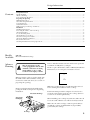
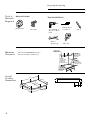
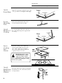
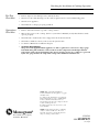
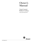
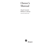
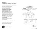
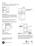
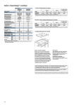
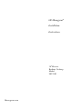
GE Monogram®
Installation
Instructions
30″ Electric
Radiant Cooktop
Model
ZEU30R
Monogram.com
Before you begin—Read these instructions completely and carefully.
IMPORTANT—Save these instructions for local inspector’s use.
IMPORTANT—OBSERVE ALL GOVERNING CODES AND ORDINANCES.
Note to Installer—Be sure to leave these instructions with the Consumer.
Note to Consumer—Keep these instructions for future reference.
Note—This appliance must be properly grounded.
ATTENTION INSTALLER: ALL COOKTOPS MUST BE HARD WIRED (DIRECT WIRED) INTO
AN APPROVED JUNCTION BOX. A “PLUG AND RECEPTACLE” IS NOT PERMITTED ON
THESE PRODUCTS.
!
WARNING
This appliance must be properly grounded. See “Electrical Connections,” page 7.
If you have questions concerning the installation
of this product, call the GE Answer Center®
Consumer Information Service at 800.626.2000,
24 hours a day, 7 days a week or visit our website
at: Monogram.com.
If you received a damaged cooktop, you should
contact your dealer.
Proper installation is the responsibility of the
installer. Product failure due to improper installation
is not covered under the GE Appliance Warranty. See
the Owner’s Manual for warranty information.
For Monogram local service in your area,
1.800.444.1845.
For Monogram Service in Canada,
1.888.880.3030.
For Monogram Parts and Accessories,
call 1.800.626.2002.
FOR YOUR SAFETY:
• For Personal Safety, remove house fuse or open
circuit breaker before beginning installation.
Failure to do so could result in serious injury
or death.
• Be sure your cooktop is installed properly by a
qualified installer or service technician.
• To eliminate the risk of burns or fire by reaching
over heated surface elements, cabinet storage
located above the surface units should be avoided.
If cabinet storage space is to be provided, the risk
can be reduced by installing a range hood that
projects horizontally a minimum of 5″ beyond the
bottom of the cabinets. Cabinet installation above
the cooktop may be no deeper than 13″.
• Make sure the cabinets and wall coverings around the
cooktop can withstand the temperatures (up to 200°F)
generated by the cooktop.
• The cooktop should be easy to reach and lighted with
natural light during the day.
• Always disconnect the electrical service to the cooktop
before repairing or servicing the cooktop. This can be
done by disconnecting the fuse or circuit breaker.
Failure to do this could result in a dangerous or fatal
shock. Know where your main disconnect switch is
located. If you do not know, have your electrician
show you.
Check local building codes for the proper method
of cooktop installation. Local codes vary. Installation,
electrical connections and grounding must comply
with applicable codes.
Electrical Requirements
2
This appliance must be supplied with the proper voltage and frequency, and connected to an
individual, properly grounded branch circuit, protected by a circuit breaker or a time delay fuse as noted
on the rating plate.
We recommend you have the electrical wiring and hookup of your cooktop connected by a qualified
electrician. After installation, have the electrician show you where your main range disconnect
is located.
Wiring must conform to the National Electrical Code. You can get a copy of the National Electrical Code,
ANSI/NFPA No. 70-Latest Edition, by writing:
National Fire Protection Association
Batterymarch Park
Quincy, MA 02269
The cooktop conduit wiring is approved for copper wire connection only, and if you have aluminum house
wiring, you must use special UL approved connectors for joining copper to aluminum.
You must use a two-wire, three conductor 208/240VAC, 60 Hertz electrical system. A white (neutral) wire
is not needed for this unit. The cooktop must be installed in a circuit that does not exceed 125 VAC nominal
to ground. Refer to the rating plate on your cooktop for the KW rating for your cooktop.
Design Information
Electronic Radiant Cooktop
Contents
Models
Available
Advance
Planning
Design Information
Models Available ..................................................................................................................................................................... 3
Advance Planning ................................................................................................................................................................... 3
Tools & Materials Required ................................................................................................................................................... 4
Preparing the Opening
Minimum Clearances ............................................................................................................................................................. 4
Overall Cooktop Dimensions ................................................................................................................................................. 4
Vertical Clearance .................................................................................................................................................................. 5
Cutout Dimensions ................................................................................................................................................................. 5
Wall Coverings, Countertop & Cabinets ............................................................................................................................... 5
Installation
Installing Junction Box ........................................................................................................................................................... 5
Protecting the Surface of the Cooktop................................................................................................................................. 5
Attach Foam Strips ................................................................................................................................................................. 6
Locate Mounting Parts .......................................................................................................................................................... 6
Attach Brackets to Cooktop .................................................................................................................................................. 6
Insert the Cooktop into Cutout ............................................................................................................................................. 6
Attach the Hold Down Bracket ............................................................................................................................................. 6
Electrical Connections ........................................................................................................................................................... 7
Checking Installation & Cooktop Operations ...................................................................................................................... 8
ZEU30R
Electronic Radiant Cooktop
!
The electrical power to the
cooktop supply line must be shut
off while connections are being
made. Failure to do so could
result in serious injury or death.
Remove Installation Instructions from literature pack and
read them carefully before you begin.
Be sure to place all literature, Owner’s Manual, Installation
Instructions, etc. in a safe place for future reference.
GE Monogram®
Installation
Instruction
When preparing cooktop opening, make sure
the inside of the cabinet and the cooktop do
not interfere with each other. (See section on
preparing the opening.)
Remove packaging materials and literature
package from the cooktop before beginning
installation.
Literature Package
Styrofoam
Packaging
30" Electric
Radiant Cooktop
Model ZEU30R
Make sure you have all the tools and materials you need
before starting the installation of the cooktop.
Your home must provide the adequate electrical service
needed to safely and properly use your cooktop. (Refer to
section on electrical requirements.)
When installing your cooktop in your home, make sure all
local codes and ordinances are followed exactly as stated.
HOT
ON
Make sure the wall coverings, countertop and cabinets
around the cooktop can withstand heat (up to 200°F)
generated by the cooktop.
Cooktop
3
Preparing the Opening
Electronic Radiant Cooktop
Tools &
Materials Needed
Materials
Required
Junction Box
Tools You Will Need
Phillips Head
Screwdriver
1/8″ Drill Bit &
Electric or Hand
Drill
Wire Nuts
Ruler or
Straightedge
Minimum
Clearances
Pencil
Saber Saw
13" MAX. Depth
of unprotected
overhead cabinets
The following MINIMUM clearance
dimensions must be maintained.
1 1/2" MIN.
clearance from
cutout to side
wall on the right
of the unit
30" MIN.
clearance from
countertop to
unprotected
overhead surface
18" MIN.
height from
countertop to
nearest cabinet on
either side of unit
2" MIN.
clearance from
cutout to side
wall on the left
of the unit
Overall
Cooktop
Dimensions
29 3/4"
20 7/8"
6 1/4"
20 7/8"
C
L
3 1/4"
5 1/2"
19 1/4"
4
3 1/4"
21 7/16"
28"
CURVED GLASS
Installation
Electronic Radiant Cooktop
Vertical
Clearance
Five inches (5″) minimum vertical clearance between
the cooktop bottom and any combustible surfaces.
5"Min.
Vertical Clearance
Cutout
Dimensions
of the
Countertop
To insure accuracy, it is best to make a
template when cutting the opening in the
counter. Make sure there is clearance
inside the cabinet before cutting the
countertop.
Wall
Coverings,
Countertop
& Cabinets
Make sure the wall coverings, countertop and
cabinets around the cooktop can withstand heat
(up to 200°F) generated by the cooktop.
Installing
the
Junction
Box
1 3/4" Min.
Between cutout
rear edge and the
wall behind the cooktop
2"
2 "Min.
Min.from
from
front edge of cutout
and front edge of countertop
Wall covering,
cabinets and
countertop must
withstand heat up
to 200°F.
Install an approved junction box where it
can be easily reached through the front of
the cabinet where the cooktop will be
located. The cooktop conduit is 3 feet long.
!
Protect
Surface of
Cooktop
19 5/8" width of cut
28 1/2"
length
of cut
IMPORTANT: The junction box
must be located where it will allow
considerable slack in the conduit
for serviceability.
Place a towel or tablecloth onto the
countertop. Lay the cooktop upside down
onto the protected surface.
16"
Min.
Install junction box
so that it can be reached
through the front of
the cabinet.
Bottom of cooktop
Cloth under Cooktop
(Continued on following page)
5
Installation
Electronic Radiant Cooktop
Attach
Foam Strips
Bottom of
Cooktop
Apply the foam strips around the outer edge
of the glass. Do not overlap the foam strips.
Foam Strips
Cooktop
Glass
Locate
Mounting
Parts
Remove the hold down brackets and
screws from the literature package.
Attach
Brackets to
Cooktop
Screw the Hold Down Bracket to the side of
the cooktop unit. Repeat for opposite side
of cooktop.
MOUNTING
SCREW
Pre-drilled
hole
Bottom of
Cooktop
Foam Strips
Cooktop
Glass
Insert
Cooktop
Into
Cutout
Insert the cooktop centered into the
cutout opening. Make sure the front
edge of the countertop is parallel to
the cooktop. Make final check that all
required clearances are met.
COOKTOP
Hold
Down
Bracket
IMPORTANT: If the cooktop
is being installed into a blind
counter (one with no cabinet
opening below), wire connections
must be made before putting the cooktop
into the cutout opening.
!
Attach
Hold Down
Brackets to
Cabinet
Open the cabinet door and screw the Hold
Down Brackets to the cabinet sides with the
screws provided.
MOUNTING
SCREW
CABINET
SIDE
6
BURNER BOX
SIDES
USE SUITABLE
FASTENERS FOR
ANCHORAGE IN
CABINET SIDES
Electrical Connections
Electronic Radiant Cooktop
Step
1
When making the wire connections, use the entire length of conduit provided. The conduit must not be
shortened.
2
With the cooktop in place, open the front of the cabinet door.
Step
Step
3
Insert the wires from the conduit through the opening
of the junction box.
Ground
Step
4
Black
Connect the red and black leads from the
cooktop conduit to the corresponding leads
in the junction box.
Red
Ground
wire
location
Step
5
Strain
Relief
Clamp
Red
Black
Red
Once the connections are made, secure wires
together using wire nuts.
Strain
Relief
Clamp
Ground
Black
GROUNDING INSTRUCTIONS
The bare ground wire in the conduit is connected to the cooktop frame. Effective January 1, 1996, the
National Electrical Code will not permit grounding through neutral. If used in new construction after
January 1, 1996 or in a mobile home, recreational vehicle or if local codes do not permit grounding
through the neutral white lead, attach the appliance grounding lead (green or copper) to the residence
grounding conductor (green or bare copper) in accordance with local codes. When connecting to a 3
conductor branch circuit, if local codes permit, connect the bare ground connector lead of the cooktop to
the branch circuit neutral (gray or white in color).
IMPORTANT: If the cooktop is being installed into a blind counter (one with no cabinet opening below),
wire connections must be made before putting the cooktop into the cutout opening.
NOTE: ALUMINUM WIRING
A. WARNING:
IMPROPER CONNECTION OF ALUMINUM HOUSE WIRING TO THE COPPER LEADS CAN
RESULT IN A SERIOUS PROBLEM.
B. Splice copper wires to aluminum wiring using special connectors designed and UL approved for joining
copper to aluminum and follow the manufacturer’s recommended connector procedure closely.
NOTE: Wire used, location and enclosure of splices, etc., must conform to good wiring practice and
local codes.
7
Checking the Installation & Cooktop Operation
Electronic Radiant Cooktop
Pre-Test
Checklist
• Remove all protective film if present, and any stickers.
• Check to be sure that all wiring is secure and not pinched or in contact with moving parts.
• Check level of appliance.
• Check that the cooktop is properly grounded.
Operation
Checklist
• Remove all items from the top of the cooktop surface.
• Turn on the power to the cooktop. (Refer to your Owner’s Manual.) Verify that all surface units
operate properly.
• Check that the circuit breaker is not tripped nor the house fuse blown.
• Check that conduit is securely connected to the junction box.
• See Owner’s Manual for troubleshooting list.
•
NOTE TO ELECTRICIAN:
The power leads supplied with this appliance are UL recognized for connections to larger gauge
household wiring. The insulation of these leads is rated at temperatures much higher than the
temperature rating of household wiring. The current carrying capacity of a conductor is governed
by the wire gauge and also the temperature rating of the insulation around the wire.
NOTE: While performing installations
described in this book, safety glasses or goggles
should be worn.
To obtain specific information concerning any
Monogram product or service, call GE Answer
Center® consumer information service at
800.626.2000—any time, day or night or visit our
website at: Monogram.com.
For Monogram local service in your area, call
1.800.444.1845.
®
Monogram
General Electric Company
Louisville, KY 40225
NOTE: Product improvement is a continuing
endeavor at General Electric. Therefore,
materials, appearance and specifications are
subject to change without notice.
31-10543
229C4053P527
(09/02 JR)