1
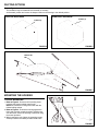
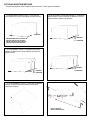
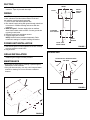
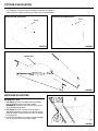
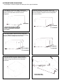
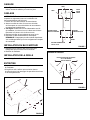
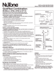
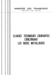
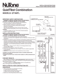
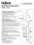
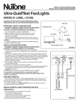
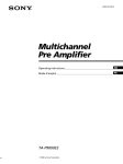
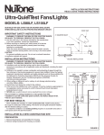
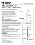
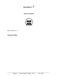
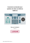
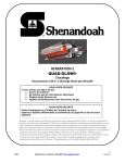
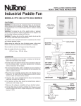
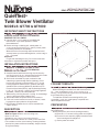
INSTALLATION INSTRUCTIONS
READ & SAVE THESE INSTRUCTIONS!
QuieTTest ®
Twin Blower Ventilator
MODELS: QT 700 & QT1000
IMPORTANT SAFETY INSTRUCTIONS
WARNING: TO REDUCE THE RISK OF FIRE.
ELECTRIC SHOCK, OR INJURY TO PERSONS,
OBSERVE THE FOLLOWING:
A. Use this unit only in the manner intended by the
manufacturer. If you have questions, contact
the manufacturer.
B. Before servicing or cleaning unit, switch power off
at service panel and lock service panel to prevent power
from being switched on accidentally.
When the service disconnecting means cannot be locked,
securely fasten a prominent warning device, such as a tag, to
the service panel.
CAUTION:
For general ventilating use only. Do not use to exhaust
hazardous or explosive materials and vapors.
HOUSING DIMENSIONS
57⁄8"
147⁄8"
231⁄4"
INSTALLATION INSTRUCTIONS
WARNING: TO REDUCE THE RISK OF FIRE,
ELECTRIC SHOCK, OR INJURY TO PERSONS,
OBSERVE THE FOLLOWING:
A. Installation work and electrical wiring must be done by
qualified person(s) in accordance with all applicable codes
and standards, including fire-rated construction.
B. Sufficient air is needed for proper combustion and
exhausting of gases through the flue (chimney) of fuel
burning equipment to prevent back drafting. Follow the
heating equipment manufacturer’s guideline and safety
standards such as those published by the National Fire
Protection Association (NFPA), and the American Society
for Heating, Refrigeration, and Air Conditioning Engineers
(ASHRAE), and the local code authorities.
C. When cutting or drilling into wall or ceiling, do not damage
electrical wiring and other hidden utilities.
D. Ducted fans must always be vented to the outdoors.
E. If this unit is to be installed over a tub or shower, it must
be marked as appropriate for the application.
F. NEVER place a switch where it can be reached from
a tub or shower.
DESCRIPTION
• Designed for ceiling installation.
• Refer to Figure 8. Not for use in cooking area.
• Uses 6" x 19" duct.
• Suitable for use with solid-state speed controls.
• Do not cover with insulation of a value greater than R-40.
• The ventilator consists of the housing, mounting brackets,
junction box, power unit/blower assembly, damper section
and grille assembly.
157⁄16"
1815⁄16"
2111⁄16"
7"
FIGURE 1
FOR BEST RESULTS
Refer to Figure 1 for dimensions of the housing.
When installing the ventilator in a new construction site,
install housing during the rough-in construction of the
building. The power unit and grille should be installed after
the finished ceiling is in place.
To install the ventilator in an existing building, an
accessible area (attic or crawl space) is required from
above the planned location.
PREPARATION
Unplug the electrical connector from the blower. Do not
pull on plug wires.
Remove the power unit from the housing assembly.
(a) Remove 91⁄16" hex nuts holding power unit in place.
(b) Pivot the blower assembly slightly toward the back
of the housing and lift straight out.
(c) Set the power unit aside.
DUCTING OPTIONS
Refer to Figures 2 and 3.
The ventilators may be ducted either horizontally or vertically.
As illustrated, position and secure the damper section to the housing in the desired position.
VERTICAL DISCHARGE
HORIZONTAL DISCHARGE
SCREWS (8)
FIGURE 2
SCREWS (8)
FIGURE 3
VENTILATOR
UNIT
FIGURE 4
MOUNTING THE HOUSING
TYPICAL MOUNTING
1. Refer to Figure 4. Provide a solid mounting frame
to assure the lowest possible sound levels.
NOTE: Be certain the housing will be flush with the
finished ceiling surface.
2. Refer to Figure 5. Position the housing against the
frame and trace the mounting bracket's keyhole slots
onto the frame. Secure the housing to the frame using
the screws provided.
3. When hanging the unit, tighten the mounting screws
securely to assure the lowest possible sound levels.
FIGURE 5
OPTIONAL MOUNTING METHODS
The mounting brackets may be adjusted and/or moved for various types of installation.
To adjust bracket position, loosen 7⁄16" hex nuts and
move brackets up or down. Re-tighten hex nuts securely.
Reverse brackets to allow approximately 1" of additional
clearance space. remove hex nuts, flip brackets over and
replace hex nuts. Tighten nuts securely.
11⁄4" MAXIMUM
17⁄16"MINIMUM
TO
27⁄16" MAXIMUM
MOUNTING BRACKETS LOCATED
ON EACH SIDE OF THE HOUSING
ARE ADJUSTABLE TO ALLOW FOR
VARIOUS CEILING THICKNESSES
To move brackets, remove 7⁄16" hex nuts. Re-position
brackets on different set of slots. Replace hex nuts and
tighten securely.
12" MINIMUM
TO
13" MAXIMUM
133⁄16" MINIMUM
TO
143⁄16" MAXIMUM
For in-line installation, remove 7⁄16" hex nuts. Re-position
brackets so that the housing's opening is at the side
instead of the bottom.
INSTALLATION IN
METAL CEILING JOISTS
DUCTING
1. Refer to Figure 6. Connect the ductwork to damper/duct
connector. Tape all joints with duct tape.
GREEN
GREEN
GROUND
SCREW
BLACK
WIRING
NOTE: All wiring connections must comply with local
codes, ordinances and the National Electric Code and
the ventilator must be properly grounded.
1. Loosen screws and remove junction box.
2. Run 120vAC supply wiring with ground through switch box
to knockout in ventilator housing and secure with box
connector.
3. Refer to Figure 7. Connect supply wires to ventilator
wires: black to black, white to white. Connect ground wire
to green ground screw.
4. Replace junction box and tighten screws.
5. Connect supply wire to switch.
NOTE: Switch must be purchased separately. Refer
to NuTone's catalog for complete ordering information.
WHITE
STANDARD
WALL SWITCH
SWITCH
BOX
EARTH
GROUND
120vAC, 60 Hz
HOUSE POWER
POWER UNIT INSTALLATION
FIGURE 7
1. Reinstall the power unit and tighten the hex nuts securely
to assure minimum sound levels.
2. Plug in blower.
COOKING AREA
GRILLE INSTALLATION
Install the grille using the screws provided.
DO NOT INSTALL ABOVE OR INSIDE
THIS AREA
MAINTENANCE
• Disconnect the power before cleaning or performing any
maintenance on the ventilator.
• If the grille becomes dirty, use only a mild soap and water
solution for cleaning. Do not use solvents or abrasive
cleaners.
45°
45°
COOKING
EQUIPMENT
FLOOR
FIGURE 8
FIGURE 6
INSTRUCTIONS D'INSTALLATION
LIRE ET CONSERVER CES INSTRUCTIONS
Ventilateur QuieTTest ®
à rotor double
DIMENSIONS DU BOITIER
157⁄16 PO
1815⁄16 PO
MODELES: QT 700 & QT1000
DESCRIPTION
• Concu pour installation au plafond.
• ATTENTION: Pour réduire le risque de décharge électrique,
57⁄8
PO
147⁄8
PO
couper le courant avant tout entretien.
• Voir Figure 8. Ne pas utiliser dans les espaces réservés
à la cuisson.
231⁄4 PO
• Utilise une gaine de 6 po x 19 po.
• Convient à une utilisation avec régulateur de vitesse
à semi-conducteurs.
• Ne pas recouvrir d'isolant ayant un indice supérieur à R-40.
• Le ventilateur comprend: le boîtier, les pattes de fixation,
2111⁄16 PO
7 PO
le boîtier de raccordement, l'ensemble bloc-moteur/rotors,
le registre et la grille.
IMPORTANTES DIRECTIVES DE SÉCURITÉ
AVERTISSEMENT: POUR RÉDUIRE LES RISQUES
D’INCENDIE, DE CHOC ÉLECTRIQUE OU DE
BLESSURES, RESPECTER CE QUI SUIT:
A. Utiliser cet appareil seulement pour les fins prévues par
le fabricant. Pour toute question, communiquer avec le
fabricant.
B. Avant de faire l’entretien ou le nettoyage de l’appareil,
couper le courant au tableau de distribution pour éviter
que le courant ne soit remis accidentellement.
Lorsque vous ne pouvez verrouiller l'interrupteur,
placez un avertissement clairement visible, par
exemple une étiquette, sur le tableau de distribution.
ATTENTION:
Pour ventilation générale seulement. Ne pas utiliser pour
évacuer des vapeurs ou des matières dangereuses ou
explosives.
DIRECTIVES D' INSTALLATION
AVERTISSEMENT: POUR RÉDUIRE LES RISQUES
D’INCENDIE, DE CHOC ÉLECTRIQUE OU DE
BLESSURES, RESPECTER CE QUI SUIT:
A. Les travaux d’installation et d’électricité doivent être
confiés à des personnes qualifiées, conformément aux
normes et aux codes en vigueur, notamment en ce qui
concerne les normes de protection contre les incendies.
B. Pour éviter les retours d’air, les appareils de chauffage
doivent avoir suffisamment d’air pour assurer une
combustion et une évacuation appropriées des gaz.
Suivre les directives du fabricant de l’appareil de
chauffage ainsi que les normes de sécurité édictées par
des organismes comme la National Fire Protection
Association (NFPA), l’American Society for Heating,
FIGURE 1
Refrigeration and Air Conditioning Engineers ou les
organismes de réglementation locaux.
C. Lorsque vous percez les murs et plafonds, éviter
d’endommager les fils électriques et les autres
canalisations.
D. Les ventilateurs dotés de tuyau doivent toujours être
raccordés à l’extérieur.
E. Si cet appareil doit être installé au-dessus d’un bain ou
d’une cabine de douche, il doit être identifié comme
convenant à une telle installation.
F. NE JAMAIS placer un interrupteur à la portée d’une
personne qui se trouverait dans le bain ou la douche.
POUR DE MEILLEURS RESULTATS
Voir Figure 1 pour les dimensions du boîtier.
Lorsqu'on installe le ventilateur dans une construction
neuve, installe le boîtier avant de procéder aux finitions. Le
bloc-moteur et la grille doivent être installés après le finition
du plafond.
Pour installer le ventilateur dans une construction
ancienne, un espace accessible au-dessus de l'emplacement
choisi pour l'installation est exiqé (qrenier ou combles.)
PREPARATION
Débrancher le raccord électrique du ventilateur. Ne pas
tirer sur les fils.
Enlever le bloc-moteur du boîtier.
(a) Enlever les écrous hexagonaux de 9⁄16 po retenant
le bloc-moteur.
(b) Faire pivoter légèrement le bloc-moteur vers l'arrière
du boîtier et soulever verticalement.
(c) Mettre le bloc-moteur de côté.
OPTIONS D'EVACUATION
Voir Figures 2 et 3.
Les ventilateurs sont prévus pour évacuation horizontale ou verticale.
Placer et fixer le registre au boîtier en position voulue, comme illustré.
EVACUATION VERTICALE
EVACUATION HORIZONTALE
VIS (8)
VIS (8)
FIGURE 2
FIGURE 3
VENTILATEUR
FIGURE 4
MONTAGE DU BOITIER
MONTAGE TYPE
1. Voir Figure 4. Prévoir un solide cadre de montage
pour un niveau sonore le plus bas possible.
REMARQUE: S'assurer que le boîtier vienne au ras
de la surface du plafond fini.
2. Voir Figure 5. Placer le boîtier contre le cadre et
reproduire les fentes en forme de trou de serrure des
pattes de fixation. Fixer le boîtier au cadre en utilisant
les vis fournies.
3. En fixant le ventilateur, bien serrer les vis de montage
pour un niveau sonore le plus bas possible.
FIGURE 5
AUTRE METHODES DE MONTAGE
On peut ajuster ou enlever les pattes de fixation pour divers types d'installation.
Pour adjuster la position des pattes, desserrer les
écrous hexagonaux de 7⁄16 po et déplacer les pattes vers
le haut ou vers le bas. Bien resserrer les écrous
hexagonaux.
Retourner les pattes pour permettre environ 1 po
d'espace supplémentaire. Enlever les écrous hexagonaux,
retrourner les pattes et replacer les écrous hexagonaux.
Bien serrer les écrous.
11⁄4 PO MAXIMUM
17⁄16 PO MINIMUM
A
27⁄16 PO MAXIMUM
LES PATTES DE FIXATION PLACEES DE
CHAQUE COTE DU BOITIER SE REGLENT
SELON LES DIFFERENTES EPAISSEURS
DE PLAFOND.
Pour ôter les pattes, enlever les écrous hexagonaux
de 7⁄16 po. Replacer les pattes sur les autres jeux de fentes.
Replacer les écrous hexagonaux et bien serrer.
12 PO MINIMUM
A
13 PO MAXIMUM
133⁄16 PO MINIMUM
A
143⁄16 PO MAXIMUM
Pour une installation en ligne, enlever les écrous
hexagonaux de 7⁄16 po. Replacer les pattes de manière
à ce que l'ouverture du boîtier soit sur le côté plutôt
qu'à la base.
INSTALLATION AVEC
SOLIVES METALLIQES
GAINAGE
1. Voir Figure 6. Raccorder le registre à l'évacuation.
Utiliser une bande adhésive pour tous les joints.
VERT
VIS DE
TERRE
VERTE
NOIR
CABLAGE
REMARQUE: Tous les raccords de câblage doivent
respecter les règlements locaux et le ventilateur doit
être convenablement relié à la terre.
1. Enlever les vis et être le boîtier de raccordement.
2. Amener un câble de 120v CA avec terre du boîtier
de l'interrupteur au raccord du boîtier de raccordement
en passant par la prédécoupe.
3. Voir Figure 7. Raccorder les fils d'alimentation aux fils
du ventilateur: le noir avec le noir, le blanc avec le blanc.
Raccorder le fil de terre à la vis de terre verte.
4. Replacer le boîtier de raccordement et serrer les vis.
5. Reccorder le câble d'alimentation à l'interrupteur.
REMARQUE: L'interrupteur peut être acheté séparément.
Voir le catalogue NuTone pour les rensignements comlpets
de commande.
INSTALLATION DU BLOC-MOTEUR
1. Replacer le bloc-moteur et bien serrer les écrous
hexagonaux pour un niveau sonore minimum.
2. Brancher le ventilateur.
BLANC
INTERRUPTEUR
MURAL STANDARD
BOITIER
D'INTERRUPTEUR
TERRE
COURANT DOMESTIQUE
120vCA, 60 Hz
FIGURE 7
ESPACE DE CUISSON
INSTALLATION DE LA GRILLE
NE PAS INSTALLER AU-DESSUS
OU A L'INTERIEUR
DE CET ESPACE
Installer la grille en utilisant les vis fournies.
ENTRETIEN
• Couper le courant avant tout nettoyage ou entretien
du ventilateur.
• Si la grille se salit, n'utiliser qu'une solution d'eau et
de savon doux pour le nettoyage. Ne pas utiliser de solvant
ou de nettoyant abrasif.
45°
45°
EQUIPMENT
DE CUISSON
PLANCHER
FIGURE 8
FIGURE 6
One Year Limited Warranty
WARRANTY OWNER: NuTone warrants to the original consumer purchaser of its products that such products will be free from defects in materials or workmanship for a period
of one (1) year from the date of original purchase. THERE ARE NO OTHER WARRANTIES, EXPRESS OR IMPLIED, INCLUDING, BUT NOT LIMITED TO, IMPLIED
WARRANTIES OF MERCHANTABILITY OR FITNESS FOR A PARTICULAR PURPOSE.
During this one year period, NuTone will, at its option, repair or replace, without charge, any product or part which is found to be defective under normal use and service.
THIS WARRANTY DOES NOT EXTEND TO FLUORESCENT LAMP STARTERS OR TUBES, FILTERS, DUCT, ROOF CAPS, WALL CAPS AND OTHER ACCESSORIES
FOR DUCTING. This warranty does not cover (a) normal maintenance and service or (b) any products or parts which have been subject to misuse, negligence, accident,
improper maintenance or repair (other than by NuTone), faulty installation or installation contrary to recommended installation instructions.
The duration of any implied warranty is limited to the one year period as specified for the express warranty. Some states do not allow limitation on how long an implied warranty
lasts, so the above limitation may not apply to you.
NUTONE’S OBLIGATION TO REPAIR OR REPLACE, AT NUTONE’S OPTION, SHALL BE THE PURCHASER’S SOLE AND EXCLUSIVE REMEDY UNDER THIS
WARRANTY. NUTONE SHALL NOT BE LIABLE FOR INCIDENTAL, CONSEQUENTIAL OR SPECIAL DAMAGES ARISING OUT OF OR IN CONNECTION WITH
PRODUCT USE OR PERFORMANCE. Some states do not allow the exclusion or limitation of incidental or consequential damages, so the above limitation or exclusion may
not apply to you. This warranty gives you specific legal rights, and you may also have other rights, which vary from state to state. This warranty supersedes all prior warranties.
WARRANTY SERVICE: To qualify for warranty service, you must (a) notify NuTone at the address stated below or telephone 1/800-543-8687, (b) give the model
number and part identification and (c) describe the nature of any defect in the product or part. At the time of requesting warranty service, you must present
evidence of the original purchase date.
Date of Installation
Builder or Installer
Model No. and Product Description
IF YOU NEED ASSISTANCE OR SERVICE:
For the location of your nearest NuTone Independent Authorized Service Center:
Residents of the contiguous United States Dial Free 1-800-543-8687
Please be prepared to provide:
Product model number • Date and Proof of purchase • The nature of the difficulty
Residents of Alaska or Hawaii should write to: NuTone Inc. Attn: Department of National Field Service, 4820 Red Bank Road, Cincinnati Ohio 45227-1599.
Residents of Canada should write to: Broan-NuTone Canada, 1140 Tristar Drive, Mississauga, Ontario, Canada L5T 1H9.
Rev. 03/2001
Garantie limitée d’un an
GARANTIE DU PROPRIÉTAIRE: NuTone garantie à l'acheteur original de ses produits que ces derniers seront exempts de tout défaut de matériaux et de fabrication pour une période
d’un (1) an à compter de la date d'achat. AUCUNE AUTRE GARANTIE, IMPLICITE OU EXPRESSE, N'EST DONNÉE, Y COMPRIS, MAIS SANS S'Y LIMITER, GARANTIE DE
MARCHANDIBILITÉ OU D'ADAPTATION À UN USAGE PARTICULIER.
Pendant cette période d’un an, NuTone procédera au remplacement ou à la réparation sans aucuns frais, mais à sa propre discrétion, de tout produit ou pièce jugé défectueux dans
le cadre d'une utilisation normale. CETTE GARANTIE NE VISE PAS LES DISPOSITIFS D'AMORÇAGE NI LES TUBES DES LUMINAIRES FLUORESCENTS. Cette garantie ne
couvre pas (a) l'entretien et le service courants ni (b) les produits et les pièces ayant fait l'objet d'un usage abusif, de négligence, d'un accident, d'un entretien ou d'une réparation non
appropriée (par du personnel non autorisé par NuTone), d'une mauvaise installation ou d'une installation non conforme aux directives d'installation fournies.
La durée de toute garantie implicite est limitée à la période de deux ans précisée pour la garantie expresse. Certains états ne reconnaissent pas les restrictions relatives à la durée des
garanties implicites; il se pourrait donc que cette restriction ne s'applique pas dans votre cas.
LE REMPLACEMENT OU LA RÉPARATION PAR NUTONE, À SA PROPRE DISCRÉTION, DE TOUT PRODUIT OU PIÈCE DÉFECTUEUX CONSTITUE LE SEUL REMÈDE DE
L'ACHETEUR EN VERTU DE CETTE GARANTIE. NUTONE NE PEUT ÊTRE TENUE RESPONSABLE DES DOMMAGES INDIRECTS, CONSÉCUTIFS OU SPÉCIAUX
ATTRIBUABLES À L'UTILISATION OU AU RENDEMENT DU PRODUIT. Certains états ne reconnaissent pas les restrictions ni les exclusions relatives aux dommages indirects,
consécutifs ou spéciaux; il se pourrait donc que cette restriction ne s'applique pas dans votre cas. La présente garantie vous accorde des droits spécifiques, mais vous pourriez aussi
avoir d'autres droits en fonction de l'état dans lequel vous résidez. Cette garantie remplace toute autre garantie donnée précédemment.
SERVICE SOUS GARANTIE Pour être admissible au service sous garantie, vous devez (a) aviser NuTone, à l'adresse fournie ci-dessous ou par téléphone au 1 800 5433687, (b) fournir le numéro du modèle et la description de la pièce et (c) décrire la nature du défaut de la pièce ou du produit. Au moment de la demande de service sous
garantie, vous devez fournir une preuve de la date d'achat originale.
Date d’installation
Entrepreneur ou installateur
N° de modèle et description du produit
POUR OBTENIR DE L’ASSISTANCE OU DU SERVICE:
Pour connaître le Centre de service NuTone autorisé indépendant le plus proche:
Résidents des États-Unis continentaux, composez le numéro sans frais: 1 800 543 8687
Garder à protée de la main le numéro du modèle, la date et la preuve d’achat, le type de problème.
Résidents de l’Alaska et d’Hawaii: Écrivez à NuTone Inc. Attn: Department of National Field Service, 4820 Red Bank Road, Cincinnati Ohio USA 45227-1599.
Résidents du Canada: Écrivez à Broan-NuTone Canada, 1140 Tristar Drive, Mississauga, Ontario Canada L5T 1H9.
Rev. 03/2001
Product specifications subject to change without notice.
Les caractéristiques de produits peuvent changer san prévis.
4820 Red Bank Road, Cincinnati, Ohio 45227
1140 Tristar Drive, Mississauga, Ontario, Canada L5T 1N2
Printed in U.S.A., Imprimé aux E.U.
Rev. 04/01, Part No. 36468