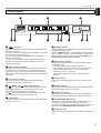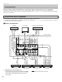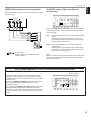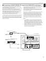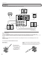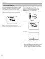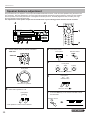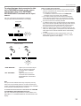
1
UCAT
R-V1105
Natural Sound AV Receiver
Ampli-tuner audio vidéo
OWNER’S MANUAL
MODE D’EMPLOI
• Explanation of Graphical Symbols
CAUTION
RISK OF ELECTRIC SHOCK
DO NOT OPEN
CAUTION: TO REDUCE THE RISK OF
ELECTRIC SHOCK, DO NOT REMOVE
COVER (OR BACK). NO USER-SERVICEABLE
PARTS INSIDE. REFER SERVICING TO
QUALIFIED SERVICE PERSONNEL.
IMPORTANT
Please record the serial number of your unit
in the space below.
Model:
Serial No.:
The serial number is located on the rear of
the unit.
Retain this Owner’s Manual in a safe place
for future reference.
The lightning flash with arrowhead
symbol, within an equilateral triangle,
is intended to alert you to the
presence of uninsulated “dangerous
voltage” within the product’s
enclosure that may be of sufficient
magnitude to constitute a risk of
electric shock to persons.
The exclamation point within an
equilateral triangle is intended to alert
you to the presence of important
operating and maintenance
(servicing) instructions in the literature
accompanying the appliance.
WARNING
TO REDUCE THE RISK OF FIRE OR ELECTRIC
SHOCK, DO NOT EXPOSE THIS UNIT TO RAIN
OR MOISTURE.
SAFETY INSTRUCTIONS
1
Read Instructions – All the safety and operating
instructions should be read before the unit is operated.
2
Retain Instructions – The safety and operating instructions
should be retained for future reference.
3
Heed Warnings – All warnings on the unit and in the
operating instructions should be adhered to.
4
Follow Instructions – All operating and other instructions
should be followed.
5
6
Water and Moisture – The unit should not be used near
water – for example, near a bathtub, washbowl, kitchen
sink, laundry tub, in a wet basement, or near a swimming
pool, etc.
Carts and Stands – The unit should be used only with a
cart or stand that is recommended by the manufacturer.
6A A unit and cart combination should be
moved with care. Quick stops, excessive
force, and uneven surfaces may cause
the unit and
cart combination to overturn.
7
Wall or Ceiling Mounting – The unit
should be mounted to a wall or ceiling only as
recommended by the manufacturer.
8
Ventilation – The unit should be situated so that its
location or position does not interfere with its proper
ventilation. For example, the unit should not be situated
on a bed, sofa, rug, or similar surface, that may block the
ventilation openings; or placed in a built-in installation,
such as a bookcase or cabinet that may impede the flow
of air through the ventilation openings.
9
Heat – The unit should be situated away from heat
sources such as radiators, stoves, or other appliances
that produce heat.
10 Power Sources – The unit should be connected to a power
supply only of the type described in the operating
instructions or as marked on the unit.
11 Power-Cord Protection – Power-supply cords should be
routed so that they are not likely to be walked on or
pinched by items placed upon or against them, paying
particular attention to cords at plugs, convenience
receptacles, and the point where they exit from the unit.
12 Cleaning – The unit should be cleaned only as
recommended by the manufacturer.
13 Nonuse Periods – The power cord of the unit should be
unplugged from the outlet when left unused for a long
period of time.
14 Object and Liquid Entry – Care should be taken so that
objects do not fall into and liquids are not spilled into the
inside of the unit.
15 Damage Requiring Service – The unit should be serviced
by qualified service personnel when:
A. The power-supply cord or the plug has been
damaged; or
B. Objects have fallen, or liquid has been spilled into the
unit; or
C. The unit has been exposed to rain; or
D. The unit does not appear to operate normally or
exhibits a marked change in performance; or
E. The unit has been dropped, or the cabinet damaged.
16 Servicing – The user should not attempt to service the unit
beyond those means described in the operating
instructions. All other servicing should be referred to
qualified service personnel.
17 Power Lines – An outdoor antenna should be located away
from power lines.
18 Grounding or Polarization – Precautions should be taken
so that the grounding or polarization is not defeated.
Outdoor Antenna Grounding – If an outside antenna is
connected to this unit, be sure the antenna system is
grounded so as to provide some protection against
voltage surges and built-up static charges. Article 810 of
the National Electrical Code, ANSI/NFPA 70, provides
information with regard to proper grounding of the mast
and supporting structure, grounding of the lead-in wire to
an antenna discharge unit, size of grounding conductors,
location of antenna discharge unit, connection to
grounding electrodes, and requirements for the grounding
electrode.
Note to CATV system installer:
This reminder is provided to call the CATV system
installer’s attention to Article 820-40 of the NEC that
provides guidelines for proper grounding and, in
particular, specifies that the cable ground shall be
connected to the grounding system of the building, as
close to the point of cable entry as practical.
English
19 For US customers only:
EXAMPLE OF ANTENNA GROUNDING
MAST
ANTENNA
LEAD IN
WIRE
GROUND
CLAMP
ANTENNA
DISCHARGE UNIT
(NEC SECTION 810–20)
ELECTRIC
SERVICE
EQUIPMENT
GROUNDING CONDUCTORS
(NEC SECTION 810–21)
GROUND CLAMPS
POWER SERVICE GROUNDING
ELECTRODE SYSTEM
(NEC ART 250. PART H)
NEC – NATIONAL ELECTRICAL CODE
FCC INFORMATION (for US customers only)
1. IMPORTANT NOTICE : DO NOT MODIFY THIS UNIT!
This product, when installed as indicated in the
instructions contained in this manual, meets FCC
requirements. Modifications not expressly approved by
Yamaha may void your authority, granted by the FCC, to
use the product.
2. IMPORTANT : When connecting this product to
accessories and/or another product use only high quality
shielded cables. Cable/s supplied with this product
MUST be used. Follow all installation instructions.
Failure to follow instructions could void your FCC
authorization to use this product in the USA.
3. NOTE : This product has been tested and found to
comply with the requirements listed in FCC Regulations,
Part 15 for Class “B” digital devices. Compliance with
these requirements provides a reasonable level of
assurance that your use of this product in a residential
environment will not result in harmful interference with
other electronic devices.
This equipment generates/uses radio frequencies and, if
not installed and used according to the instructions
found in the users manual, may cause interference
harmful to the operation of other electronic devices.
Compliance with FCC regulations does not guarantee that
interference will not occur in all installations. If this product
is found to be the source of interference, which can be
determined by turning the unit “OFF” and “ON”, please try
to eliminate the problem by using one of the following
measures:
Relocate either this product or the device that is being
affected by the interference.
Utilize power outlets that are on different branch (circuit
breaker or fuse) circuits or install AC line filter/s.
In the case of radio or TV interference, relocate/reorient the
antenna. If the antenna lead-in is 300 ohm ribbon lead,
change the lead-in to coaxial type cable.
If these corrective measures do not produce satisfactory
results, please contact the local retailer authorized to
distribute this type of product. If you can not locate the
appropriate retailer, please contact Yamaha Electronics
Corp., U.S.A. 6660 Orangethorpe Ave, Buena Park, CA
90620.
The above statements apply ONLY to those products
distributed by Yamaha Corporation of America or its
subsidiaries.
We Want You Listening For A Lifetime
YAMAHA and the Electronic Industries Association’s
Consumer Electronics Group want you to get the most out of
your equipment by playing it at a safe level. One that lets the
sound come through loud and clear without annoying blaring or
distortion – and, most importantly, without affecting your
sensitive hearing.
Since hearing damage from loud sounds is often
undetectable until it is too late, YAMAHA and the
Electronic Industries Association’s Consumer
Electronics Group recommend you to avoid
prolonged exposure from excessive volume levels.
Congratulations!
You are the proud owner of a Yamaha Digital Sound Field Processing (DSP)
System—an extremely sophisticated audio component. The DSP system takes full
advantage of Yamaha’s undisputed leadership in the field of digital audio processing
to bring you a whole new world of listening experiences. Follow the instructions in this
manual carefully when setting up your system, and the DSP system will sonically
transform your room into a wide range of listening environments—anything from a
famous concert hall to a cozy jazz club. In addition, you get incredible realism from
most of surround-sound encoded video sources available in the market using the builtin Dolby Pro Logic Surround Decoder, Dolby Digital Decoder and DTS Decoder.
Five built-in channels of amplification on this model mean that no additional
amplifiers are required to enjoy advanced digital sound field processing.
Rather than tell you about the wonders of digital sound field processing, however,
let’s get right down to the business of setting up the system and trying out its many
capabilities. Please read this operation manual carefully and store it in a safe place for
later reference.
English
CONTENTS
SAFETY INSTRUCTIONS
........................................... Inside of the Front Cover
BASIC OPERATION ............................................... 33
Playing a source .................................................... 33
CAUTION .................................................................. 2
Recording a source to tape (or MD) or dubbing
from tape (or MD) to tape (or MD)......................... 37
Sound control......................................................... 38
INTRODUCTION ....................................................... 3
Tuning ..................................................................... 39
Features .................................................................... 3
Basic operation ................................................... 39
What’s DSP?............................................................. 4
Preset tuning ........................................................ 40
Using digital sound field processor (DSP) ......... 43
GETTING STARTED ................................................ 7
Getting started.......................................................... 7
Playing a source with an effect of the digital
sound field processor (DSP) ................................ 43
Unpacking .............................................................. 7
Adjusting output level of the center, right rear,
left rear speakers and subwoofer......................... 46
Installing batteries in the remote controller ........... 8
Brief overview of digital sound field programs...... 48
Notes about the remote controller.......................... 8
Controls and their functions ................................... 9
ADVANCED FEATURES ....................................... 51
Front panel ............................................................. 9
Display panel........................................................ 11
“SET MENU” mode ............................................... 51
Creating your own sound fields .......................... 55
PREPARATION ...................................................... 12
Speaker setup......................................................... 12
Setting the SLEEP timer ....................................... 60
REMOTE CONTROLLER ....................................... 61
Connections ........................................................... 14
Audio/video source equipment ............................ 14
Speakers ............................................................. 20
Antennas ............................................................. 23
Plugging in this unit ............................................. 25
Basic operation ..................................................... 61
Key name and function ......................................... 62
Entering manufacturer codes .............................. 67
Restoring the default codes ................................. 68
On screen display .................................................. 26
Selecting the output modes
(“SET MENU” mode) ............................................. 27
TROUBLESHOOTING ............................................ 69
Speaker balance adjustment ................................ 30
SPECIFICATIONS .................................................. 72
LIST OF MANUFACTURE’S CODE
.............................................. The end of this manual
1
CAUTION : Read this before operating your unit.
1. To assure the finest performance, please read this manual
carefully. Keep it in a safe place for future reference.
2. Install this unit in a cool, dry, clean place – away from
windows, heat sources, sources of excessive vibration,
dust, moisture and cold. Avoid sources of humming
(transformers, motors). To prevent fire or electrical shock,
do not expose the unit to rain or water.
3. Never remove the unit cover. Contact your dealer if an
object falls inside the unit.
4. Do not use force on switches, controls or connection wires.
When moving the unit, first disconnect the power plug and
the wires connected to other equipment. Never pull on the
wires themselves.
5. The openings on the unit cover assure proper ventilation of
the unit. If these openings are obstructed, the temperature
inside the unit will rise rapidly. Therefore, avoid placing
objects against these openings, and install the unit in a
well-ventilated area to prevent fire and damage.
<Singapore model only>
Be sure to allow a space of at least 20 cm behind, 20 cm
on the both sides and 30 cm above the top panel of the
unit to prevent fire and damage.
6. The voltage used must be the same as that specified on
this unit. Using this unit with a higher voltage than
specified is dangerous and may result in fire or other
accidents. YAMAHA will not be held responsible for any
damage resulting from use of this unit with a voltage other
than specified.
7. Digital signals generated by this unit may interfere with
other equipment such as tuners, receivers or TVs. Move
this unit farther away from such equipment if interference
is observed.
8. Always set the VOLUME control to “– ∞” before starting
the audio source play. Increase the volume gradually to an
appropriate level after playback has been started.
9. Do not attempt to clean the unit with chemical solvents;
This unit is not disconnected from the AC power source as
long as it is connected to the wall outlet, even if this unit
itself is turned off. This state is called the standby mode.
In this mode, this unit is designed to consume a small
amount of power.
FREQUENCY STEP switch (China and General Models
only)
Because the interstation frequency spacing differs in
different areas, set the FREQUENCY STEP switch (located
at the rear) according to the frequency spacing in your area.
Before setting this switch, disconnect the AC power plug of
this unit from the AC outlet.
For Canadian Customers
To prevent electric shock, match wide blade of plug to wide
slot and fully insert.
This Class B digital apparatus complies with Canadian
ICES–003.
WARNING
Do not change the IMPEDANCE SELECTOR switch
setting while the power to this unit is on, otherwise this
unit may be damaged.
IF THIS UNIT FAILS TO TURN ON WHEN THE
STANDBY/ON SWITCH IS PRESSED;
The IMPEDANCE SELECTOR switch may not be set to
either end. If so, set the switch to either end when this unit
is in the standby mode.
IMPEDANCE SELECTOR
this might damage the finish. Use a clean, dry cloth.
10. Be sure to read the “TROUBLESHOOTING” section
regarding common operating errors before concluding that
the unit is faulty.
11. When not planning to use this unit for long periods of time,
disconnect the AC power plug from the wall outlet.
12. To prevent lightning damage, disconnect the AC power
plug and antenna cable when there is an electrical storm.
IMPEDANCE SELECTOR
SET BEFORE POWER ON
REAR
(SURROUND)
REAR
: 6ΩMIN. /SPEAKER
CENTER
: 6ΩMIN. /SPEAKER
MAIN A OR B: 4ΩMIN. /SPEAKER
A B: 8ΩMIN. /SPEAKER
REAR
: 8ΩMIN. /SPEAKER
CENTER
: 8ΩMIN. /SPEAKER
MAIN A OR B: 8ΩMIN. /SPEAKER
A B:I6ΩMIN. /SPEAKER
AC OUTLETS
SWITCHED
I20V 60Hz
I00W MAX. TOTAL
13. Grounding or polarization – Precautions should be taken
so that the grounding or polarization of an appliance is not
defeated.
14. Do not connect an audio unit to the AC outlet on the rear
panel if the equipment requires more power than the outlet
is rated to provide.
15. Voltage Selector (China and General Models only)
The voltage selector on the rear panel of this unit must
be set for your local main voltage BEFORE plugging
into the AC main supply.
Voltages are 110/120/220/240 V AC, 50/60 Hz.
2
(U.S.A. model)
Features
5 Channel Power Amplification
Main:
Center:
Rear:
85W + 85W (8Ω) RMS Output
Power, 0.04% THD, 20–20,000 Hz
85W (8Ω) RMS Output Power,
0.04% THD, 20–20,000 Hz
85W + 85W (8Ω) RMS Output
Power, 0.04% THD, 20–20,000 Hz
English
INTRODUCTION
Sophisticated FM/AM Tuner
● 40-Station Random Access Preset Tuning
● Automatic Preset Tuning
● Preset Station Shifting Capability (Preset
Editing)
● IF Count Direct PLL Synthesizer Tuning
System
Multi-Mode Digital Sound Field
Processing
Others
● Digital Sound Field Processor (DSP)
● Dolby Digital Decoder
● Dolby Pro Logic Surround Decoder
● DTS Decoder
● “SET MENU” Mode which Provides You
with 13 Titles of Setting Changes and
Adjustments for Optimizing This Unit for
Your Audio/Video System
● CINEMA DSP: Theater-like Sound
Experience by the Combination of
YAMAHA DSP Technology and Dolby
Digital, Dolby Pro Logic or DTS
● BASS EXTENSION Button for Reinforcing
Bass Response
● Automatic Input Balance Control for
Dolby Pro Logic Surround
● SLEEP Timer
● Test Tone Generator for Easier Speaker
Balance Adjustment
● Speaker Output Mode Selection
Capability for the Most Suitable
Use of Your Speaker System
● On Screen Display Function Helpful in
Controlling This Unit
● OPTICAL and COAXIAL Digital Audio
Signal Terminals
● 6 Channel External Decoder Input for
Other Future Formats
● Video Signal Input/Output Capability
(Including S Video Connections)
● Universal Remote Controller with Preset
Manufacturer Codes
3
INTRODUCTION
What’s DSP?
Introduction
Welcome to the exciting world of digital home entertainment.
This unit is one of the most complete and advanced AV
receiver available. Some of the more advanced features may
not be familiar to you, but they are easy to use. State-of-the-art
technologies such as Dolby Digital and Digital Theater
Systems (DTS) may be new to your home, but you have
probably experienced the amazing realism they bring to feature
films in theaters around the world.
To make the listening experience even more enjoyable, this
unit includes a number of exclusive, digitally created listening
environments known as digital sound fields. Choosing a sound
field program is like transporting yourself to such venues as an
outdoor arena, a European church, or a cozy jazz club. Take
some time now to read more about these features and enjoy
the new experiences this unit brings to your home theater.
Digital Sound Field Processing
Technological advances in sound reproduction over the last 30
years have enhanced the listening experience with improved
clarity, precision and power. However, something has still been
missing: The atmosphere and acoustic ambiance of the public
venue. Our Yamaha engineers have extensively researched
the nature of sound acoustics and the way sound reflects
inside a room. We sent these engineers to famous theaters
and concert halls around the world to measure the acoustics of
those venues with sophisticated microphones. The data they
collected is used to recreate these environments in digital
sound fields. Some of these digital sound fields are created
using data measured directly at the original venue; others are
created from combinations of data to form unique
environments for specific purposes.
Of course, that only solves half of the problem. These
engineers have no way of knowing the acoustics of your
listening room, so we’ve made it possible for you to adjust the
various parameters of this data to tailor each virtual venue to
your taste. You can use these sound fields to enhance any
source and in combination with any of the following surround
sound technologies. Some are designed especially for music,
and some especially for movies.
Dolby Pro Logic Surround
Dolby Pro Logic Surround has been used in movie theaters
since the mid-seventies. It has also been available in home
entertainment systems since the late eighties and continues to
be a popular format for home theater systems. It uses four
discrete channels and five speakers to reproduce realistic and
dynamic sound effects: two main channels (left and right), a
center channel for dialog, and a rear channel for special sound
effects. The rear channel reproduces sound within a narrow
frequency range.
4
Most video tapes and laser discs include Dolby Pro Logic
Surround encoding as do many TV and cable broadcasts. The
Dolby Pro Logic Surround decoder built into this unit employs a
digital signal processing system that stabilizes each channel
for even more accurate sound positioning than is available with
standard analog processors.
INTRODUCTION
Dolby Digital is the next level of Dolby Surround sound system
developed for 35 mm film-movies by employing low bit-rate
audio coding.
Dolby Digital is a digital surround sound system that provides
completely independent multi-channel audio to you. Dolby
Digital provides five full range channels in what is sometimes
referred to as a “3/2” configuration: three front channels (left,
center and right), and two surround channels. A sixth bass-only
effect channel is also provided for output of LFE (low frequency
effect), or low bass effects that are independent of other
channels. (This is called the “subwoofer channel” or “LFE
channel”.) This channel is counted as 0.1, thus giving rise to
the term 5.1 channels in total.
Compared to Dolby Pro Logic that is referred to a “3/1” system
(left front, center, right front and just one surround channel),
Dolby Digital features two surround channels, called stereo or
split surrounds, each offering the same full range fidelity as the
three front channels.
Dolby Digital forms 5.1 channels as mentioned left, and
moreover, it can also form fewer channels, for example 2
channel stereo and monaural. You may be able to find some 2
channel stereo and/or monaural sources encoded with Dolby
Digital in the market.
English
Dolby Digital
Laserdisc and DVD are home audio formats that could benefit
from Dolby Digital. In the near future, Dolby Digital will also be
applied to DBS, CATV and HDTV. The ongoing release of
Dolby Stereo Digital theatrical films now underway will provide
an immediate source of Dolby Digital encoded video software.
Manufactured under license from Dolby Laboratories Licensing
Corporation. “DOLBY”, “AC-3”, “Pro Logic”, and the double-D
symbol are trademarks of Dolby Laboratories Licensing
Corporation.
Copyright 1992 Dolby Laboratories, Inc. All rights reserved.
By using the built-in Dolby Digital decoder, you can experience
the dramatic realism and impact of Dolby Stereo Digital theater
sound in your home.
Wide dynamic range of sound reproduced by the five full range
channels and precise sound orientation by the digital sound
processing presents listeners much excitement and realism
that has never been experienced before.
DTS Digital Surround
DTS (Digital Theater Systems) system was developed to
replace analog soundtracks of movies with six discrete
channels of digital soundtracks, and now, it is installed in many
theaters around the world. The DTS digital playback system
changed the way we experienced movies in theaters with six
discrete channels of superb digital audio.
The DTS technology, through intense research and
development, made it possible to deliver a similar
encode/decode discrete technology to home audio surroundsound entertainment.
The DTS Digital Surround is an encode/decode system which
delivers six channels of master-quality, 20-bit audio; technically
5.1 channels, which means 5 full-range (left, center, right and
two surround) channels, plus a subwoofer (LFE) channel (as
“0.1”). It is compatible with the 5.1 speaker configurations that
are currently available for home theater systems
By using the DTS decoder built into this unit, you can
experience the dramatic realism and impact of the DTS
installed theater’s high quality sound in your home.
Laserdisc, compact disc and DVD are home audio format
within which DTS can represent its high quality multi-channel
audio. (In addition to movies on laserdiscs, many exciting new
multi-channel music recordings will also become available in
the form of DTS-encoded compact discs.)
Manufactured under license from Digital Theater Systems, Inc.
US Pat. No. 5,451,942 and other world-wide patents issued
and pending. “DTS”, “DTS Digital Surround”, are trademarks of
Digital Theater Systems, Inc. Copyright 1996 Digital Theater
Systems, Inc. All Rights Reserved.
The DTS Digital Surround algorithm is designed to encode the
six channels of 20-bit audio onto some laserdiscs, compact
discs and DVDs with considerably less data-compression.
5
INTRODUCTION
CINEMA DSP: Dolby Surround + DSP / DTS + DSP
The Dolby Surround sound and DTS systems show their full
ability in a large movie theater, because movie sounds are
originally designed to be reproduced in a large movie theater
that uses a multitude of speakers. Trying to create a sound
environment similar to that of a movie theater in your home is
difficult because of the room size, material inside the walls, the
number of speakers, and so on. In other words, your listening
room is very different from a movie theater.
However, Yamaha DSP technology allows you to create nearly
the same sound experience as that of a large movie theater in
your home by compensating for the lack of presence and
dynamics in the listening room with original digital sound fields
combined with Dolby Surround or DTS Digital Surround
sounds.
CINEMA DSP
The YAMAHA “CINEMA DSP” logo indicates those programs
that are created by the combination of YAMAHA DSP
technology and Dolby Surround or DTS.
Dolby Pro Logic + 2 Digital Sound Fields
Dolby Digital or DTS + 3 Digital Sound Fields
Digital sound fields are created on the presence side and
the rear surround side of the Dolby Pro Logic Surrounddecoded sound field respectively. They create a wide
acoustic environment and emphasize surround-effect in the
room, letting you feel much presence as if you were
watching a movie in a popular Dolby Stereo theater.
Digital sound fields are created on the presence side and
the independent left and right surround sides of the Dolby
Digital-decoded or the DTS-decoded sound field
respectively. They create a wide acoustic environment and
much surround effect in the room without losing high
channel separation. With wide dynamic range of Dolby
Digital or DTS sound, this sound field combination lets you
feel as if you were watching a movie in the newest Dolby
Stereo Digital theater or DTS installed theater. This is the
most ideal home theater sound at the present time.
This combination is available when the digital sound field
program No. 2, 3 or “PRO LOGIC/Enhanced” of No. 1 is
selected, and the input signal of the source is analog, PCM
audio or encoded with the Dolby Digital in 2-channels.
This combination is available when the digital sound field
program No. 2, 3 or “DOLBY DIGITAL (or DTS DIGITAL
SUR.)/Enhanced” of No. 1 is selected, and the input signal
of the source is encoded with the Dolby Digital (except in 2channels) or encoded with the DTS.
6
Getting started
English
GETTING STARTED
Unpacking
Carefully remove this unit and accessories from the box. You should find the unit itself and the following accessories.
Remote controller
Indoor FM Antenna
POWER
STANDBY
AMP/TUN
/DTS
SURROUND
CD
1
MONO MOVIE
DVD/LD
4
ROCK
PHONO
7
HALL
EXT. DEC.
0
MOVIE
THEATER 1
TUNER
MOVIE
THEATER 2
TAPE/MD
3
2
DISCO
TV SPORTS
VCR
TV/DBS
6
5
JAZZ CLUB
V-AUX
8
+10
CHURCH
9
TEST
+100
CLEAR
ENTER
A/B/C/D/E
DSP
EFCT
DISC SKIP
PRESET
CH
ON/OFF
CH
TV
AM Loop Antenna
CODE SET
MUTE
VOLUME
INDEX
DISP
SLEEP
POWER
VCR REC
TV
DIR
A
SUBTITLE
ON/OFF
TV INPUT
A/B
/
SET UP
ON SCREEN
SELECT
DIR
B
RETURN
ANGLE
AUDIO
TITLE
MENU
LEVEL
SET MENU
Antenna adapter (U.S.A. and Canada models only)
Batteries (size AA, R6, UM-3)
7
GETTING STARTED
Installing batteries in the remote
controller
Notes about the remote controller
Battery replacement
Since the remote controller will be used for many of this unit’s
control operations, you should begin by installing the supplied
batteries.
1.
Turn the remote controller over and slide the battery
compartment cover in the direction of the arrow.
2.
Insert the batteries (AA, R6, UM-3 type) according to the
polarity markings on the inside of the battery compartment.
3.
Close the battery compartment cover.
2
If you find that the remote controller must be used closer to the
main unit, the batteries are weak. Replace both batteries with
new ones.
Notes
● Use AA, R6, UM-3 batteries.
● Be sure the polarities are correct. (See the illustration inside
the battery compartment.)
● Remove the batteries if the remote controller is not used for
an extended period of time.
● If batteries leak, dispose of them immediately. Avoid
touching the leaked material and contact with clothing, etc.
Clean the battery compartment thoroughly before installing
new batteries.
Be sure to insert the new batteries within 2 minutes after
you remove the old batteries from the remote controller. If
the remote controller is left for more than 2 minutes without
batteries, all of the codes you entered will be cleared and
the remote controller will return to the factory preset
condition.
1
3
Remote controller operation range
Remote control
sensor
Within approximately
6 m (19.7 feet)
30°
30°
Notes
● The area between the remote controller and the main unit
must be clear of large obstacles.
● Do not expose the remote control sensor to strong lighting,
in particular, an inverter type fluorescent lamp. Otherwise,
the remote controller may not work properly. If necessary,
position the main unit away from direct lighting.
8
GETTING STARTED
English
Controls and their functions
Front panel
2
1
NATURAL SOUND
3
4
5
6
CINEMA DSP
AV RECEIVER
VOLUME
INPUT SELECTOR
l6
20
l2
28
8
60
2
4
40
STANDBY/ON
TAPE/MD MON
/EXT. DECODER
0
A/B/C/D/E
1
2
3
4
5
6
7
8
MEMORY
MAN’L/AUTO FM
PHONES
SPEAKERS
BASS
0
l
l
BASS
TONE
EXTENSION BYPASS
B
A
2
2
3
ON
OFF
ON
OFF
TREBLE
0
l
l
3
4
2
7 8 9 0A B
2
3
4
5
3
4
5
BALANCE
0
l
l
4
5
5
2
EDIT
TUNING
MODE
–dB
FM/AM
DOWN TUNING
UP
INPUT MODE
AUTO/MAN’L MONO
LEVEL
SET
MENU
VIDEO AUX
EFFECT
2
3
3
4
PROGRAM
4
L5
C
5R
S VIDEO
D E
G IJK M N
L
F H
VIDEO
L AUDIO R
O
P
For the remote controller, refer to pages 61 to 68.
1 STANDBY/ON switch
Press this switch to turn on the power. Press this switch again
to set this unit in the standby mode.
* A click from the switch and the initial rotation of the built-in
fan will be heard when the power is turned on.
Standby mode
This unit is still using a small amount of power in this mode
in order to be ready to receive infrared-signals from the
remote controller.
2 Remote control sensor
Receives signals from the remote controller.
3 Display panel
Displays a variety of information. (Refer to page 11 for details.)
4 TAPE/MD MON/EXT. DECODER button
Press this button repeatedly until the “TAPE/MD MONITOR”
indicator is illuminated on the display. Sound source played or
recorded on the unit connected to the TAPE/MD IN
(PLAY)/OUT (REC) AUDIO SIGNAL terminals on the rear of
this unit is selected as the input source taking priority of the
INPUT SELECTOR’s setting.
Press this button repeatedly until the “EXT. DECODER”
appears on the display. Sound signals input to the EXTERNAL
DECODER INPUT terminals on the rear of this unit is selected
as the input source taking priority of the INPUT SELECTOR’s
setting.
Press this button repeatedly until the original display mode is
restored to cancel the above input sources.
5 INPUT SELECTOR
Turn this knob to select the input source.
The selected source will be shown on the display.
6 Master VOLUME control
Simultaneously controls volume for all output sounds; main,
rear, center and subwoofer. (The REC OUT level is not
affected.)
* The indicator on the master VOLUME control will flash when
the volume is decreased by pressing the MUTE key on the
remote controller.
7 PHONES jack
Headphones can be plugged into this jack for private listening.
You can listen to the sound to be output from the main
speakers through headphones. When listening with
headphones privately, set both SPEAKERS A and B switches
to the OFF position and turn off the digital sound field
processor by pressing the EFFECT button so that no DSP
program name is illuminated on the display panel.
PHONES
9
GETTING STARTED
8 A/B/C/D/E button
H FM/AM button
Press this button to select a group (A–E) of preset stations.
Press this button to switch the reception band between FM and
AM.
9 SPEAKERS switches
Press the switch A or B (or both) for the main speakers you will
use inward (ON). Press and release the switch for the main
speakers you do not use outward (OFF).
0 Preset station number selector buttons
Select a preset station number (1 to 8).
I LEVEL button
This button is used to adjust the output level of the center and
rear speakers, and subwoofer. First, press this button (several
times) to select the speaker(s). The name appears on the
display. Then press the + or – button (J) to change the output
level.
A BASS EXTENSION button
Press this button inward (ON) to boost the bass frequency
response at the main left and right channels while maintaining
overall tonal balance. This function is effective for reinforcing
the bass frequencies when a subwoofer is not used.
J –/+ button
B TONE BYPASS button
Press this button inward (ON) to bypass the tone (BASS and
TREBLE) control circuitry. This function is used for outputting
pure sound and checking the tone control settings. The tone
control circuitry can be used when this button is released
outward (OFF).
K SET MENU button
C BASS and TREBLE controls
Rotate these knobs to adjust the low and high frequency
response for the left and right main channels only.
D BALANCE control
This knob controls the sound from the main speakers only.
The balance of the output volume to the left and right main
speakers can be adjusted to compensate for sound imbalances
caused by the speaker location or listening room conditions.
E MEMORY (MAN’L/AUTO FM) button
Use this button to enter a station to memory. Refer to the
section “Manual preset tuning” on page 40 for details.
Hold down this button for more than 3 seconds to start
automatic preset tuning. Refer to page 41 for details.
F EDIT button
This button is used to exchange the places of two preset
stations with each other.
G TUNING MODE (AUTO/MAN’L MONO) button
Press this button to switch the tuning mode between automatic
and manual. To select the automatic tuning mode, press this
button so that the “AUTO” indicator is illuminated on the
display. To select the manual tuning mode, press this button so
that the “AUTO” indicator is not illuminated.
10
Adjusts the level of the speaker(s) selected by pressing the
LEVEL button. Moreover, performs setting changes and
adjustments for functions selected by pressing the SET MENU
button (K).
Press this button once or more to select the desired function in
the SET MENU mode.
L TUNING DOWN/UP button
Used for tuning. Press the “UP” side to tune in to a higher
frequency, and press the “DOWN” side to tune in to a lower
frequency.
M PROGRAM selector button
Press this button in the
or
direction to select a digital
sound field processing program.
N EFFECT button
Press this button to turn on and off the output from the center
and rear speakers. The sound becomes normal 2-channel
when this function is turned off.
However, this does not apply to Dolby Digital or DTS. The
signals at all channels will be distributed to the main channels
and output from the main speakers, even if the output from the
center and rear speakers are turned off, when Dolby Digital or
DTS is decoded.
O VIDEO AUX terminals
Connect an auxiliary video or audio input source unit such as a
camcorder to these terminals. A video unit with a S video
output terminal can be connected to the S VIDEO terminal to
obtain a high resolution picture. The source can be selected
with the INPUT SELECTOR.
P INPUT MODE button
Press this button to select how input signals are received from
sources that output two or more types of signals. The “AUTO”,
“DTS” and “ANALOG” modes are available. Refer to page 36
for details.
GETTING STARTED
English
Display panel
1
2
3
DIGITAL
PRO LOGIC
DSP
MEMORY
4 5
ENHANCED MOVIE THEATER 12 TV SPORTS
MONO MOVIE
DISCO JAZZ CLUB
ROCK CONCERT CHURCH CONCERT HALL
AUTO
6
7
1
indicators
Either “dts” indicators will be illuminated when the built-in DTS
decoder is turned on.
A red “dts” indicator will be illuminated when playing a compact
disc or laserdisc encoded with DTS.
An orange “dts” indicator will be illuminated when playing a
DVD encoded with DTS.
An orange “dts” indicator may be illuminated when playing a
laserdisc encoded with DTS after a video-CD or DVD on a
DVD/LD combi-player.
STEREO
0 20
DVD/LD
CD
TV/DBS
TUNER
V-AUX
PHONO
VCR
TAPE/MD
MONITOR
SLEEP
100
89
0
A
B
6 MEMORY indicator
A flashing MEMORY indicator means a station can be saved,
as explained in the following:
Press the MEMORY button. The MEMORY indicator will flash
about 5 seconds. While the indicator is flashing, program the
displayed station to memory by using the A/B/C/D/E and the
preset station number selector buttons.
7 DSP program indicators
2 Multi-information display
This display shows the current DSP program and the status of
adjustments and setting changes. Several statuses can be
viewed at one time. The current station frequency and band
(AM or FM) will also appear when the tuner source input mode
is selected.
The name of the selected DSP program will be illuminated in
the following cases.
• When the tuner is selected as the input source
• When a DSP program parameter is selected or adjusted.
• When the DSP program No. 2, 3 or the subprogram
“Enhanced” of No. 1 is selected.
There is no illumination here when no DSP program is
selected
3 Input source indicators
8 AUTO indicator
One of the arrows for these indicators will be illuminated
depending on which source is selected.
This indicator will be illuminated during the automatic tuning
mode.
4
9 STEREO indicator
DIGITAL and
PRO LOGIC indicators
The
DIGITAL indicator will be illuminated when the built-in
Dolby Digital decoder is on and the signals of the source
encoded with Dolby Digital are not 2-channels.
The
PRO LOGIC indicator will be illuminated when the
built-in Dolby Pro Logic Surround decoder is on.
5 DSP indicator
This indicator will be illuminated when the built-in digital sound
field processor is on.
This indicator will be illuminated when an FM stereo broadcast
with sufficient signal strength is received.
0 Signal-level indicator
This indicator shows the signal level of the received station. If
multipath interference is detected, the indication decreases.
A TAPE/MD MONITOR indicator
This indicator will be illuminated when the tape deck (or MD
recorder etc.) connected to the TAPE/MD IN and OUT
terminals on the rear of this unit is selected as the input source
by pressing the TAPE/MD MON/EXT. DECODER button.
B SLEEP indicator
This indicator will be illuminated when the built-in SLEEP timer
is on.
11
PREPARATION
Speaker setup
m Setting up your speaker system
This unit has been designed to provide the best sound field
quality with a full five-speaker system setup, using a pair of
main speakers to output main source sounds, a pair of effect
speakers to generate the sound field plus one center speaker
for dialog. We therefore recommend that you use a fivespeaker setup. A four-speaker system using only one pair of
effect speakers for the sound field will still provide impressive
ambience and effects, however, and may be a good way to
begin with this unit. You can always upgrade to the fivespeaker system later.
Use of the center dialog speaker is
recommended
When playing back a source with Dolby Pro Logic decoded, or
playing back a source which contains center-channel signals
with Dolby Digital or DTS decoded, dialog, vocals etc. are
output from the center channel. Therefore, if you want to
maximize the performance of your Audio/Video home theater
system, it is recommended that you use a center channel
speaker.
If, for some reason, it is not practical to use a center speaker, it
is possible to enjoy the movie without it. Best results, however,
are obtained with the full system.
Use of a subwoofer expands your sound
field
It is also possible to further expand your system with the
addition of a subwoofer and amplifier. The use of a subwoofer
is effective not only for reinforcing bass frequencies from any
or all channels, but also for reproducing signals at the
subwoofer channel with high fidelity during playing back a
source with Dolby Digital or DTS decoded. You may wish to
choose the convenience of a Yamaha Active Servo Processing
Subwoofer System, which has its own built-in power amplifier.
m Speakers and speaker placement
Your full five-speaker system will require two speaker pairs:
the MAIN SPEAKERS (your normal stereo speakers) and the
REAR SPEAKERS, plus the CENTER SPEAKER. You may
also be using a SUBWOOFER.
The MAIN SPEAKERS should be high performance models
and have enough power handling capacity to accept the
maximum output of your audio system.
Other speakers do not have to be equal to the MAIN
SPEAKERS. For precise sound localization, however, it is
ideal to use high performance models that can reproduce
sounds in full range for the CENTER SPEAKER and REAR
SPEAKERS.
Place the MAIN SPEAKERS in the ordinary position.
Place the REAR SPEAKERS behind your listening position.
They should be nearly 1.8m above the floor.
Place the CENTER SPEAKER precisely between the two
MAIN SPEAKERS. (To avoid interference, keep the speaker
above or below the television monitor, or use a magnetically
shielded speaker.)
If using a SUBWOOFER, such as a Yamaha Active Servo
Processing Subwoofer System, the position of the speaker is
not so critical because low bass tones are not highly
directional.
Main speaker
Subwoofer
12
Center speaker
Rear speaker
PREPARATION
English
m Speaker system configurations
4 Speaker System
5 Speaker System
The recommended system for enjoying Audio/Video
sources.
By the use of a center speaker, center channel sounds (dialog,
vocals etc.) are precisely localized.
1. CENTER SPEAKER—Set to “LRG” or “SML”.
(See page 27.)
Basic system.
You can enjoy widely diffused sound by only adding a pair of
rear speakers to a basic stereo speaker system.
However, center channel sounds must be output from the left
and right main speakers.
1. CENTER SPEAKER—Set to “NONE”. (See page 27.)
13
PREPARATION
Connections
Caution: Plug in this unit and other components after all connections are completed.
All connections must be correct, that is to say L (left) to L, R (right) to R, “+” to “+” and “–” to “–”. Also refer to the owner’s manual for
each of your components.
Audio/video source equipment
●
●
Use RCA type pin plug cables for audio/video units with the exception described later.
The output (or input) terminals of YAMAHA audio/video units numbered as 1, 3, 4, etc. on the rear panel must be connected to
the same-numbered terminals of this unit.
m Basic connections
TV monitor
AUDIO OUT
VIDEO
IN
(*1)
VIDEO OUT
LD player, DVD player, etc.
GND
OUTPUT
Turntable
(U.S.A. model)
EXTERNAL DECODER INPUT
GND
MAIN
CENTER
SURROUND
75Ω UNBAL.
CD
DVD/LD
OPTICAL
COAXIAL
DVD/LD
TV/DBS
OPTICAL
DIGITAL SIGNAL
FM
ANT
S VIDEO VIDEO
ON SCREEN SELECTOR
IN
OUT
SUB
WOOFER
REMOTE
CONTROL
GND
AM
ANT
MONITOR
OUT
IN
OUT
VCR
MONITOR
OUT
IN
DVD/LD
S VIDEO SIGNAL
PHONO
CD
1
TV/DBS
OUT
VCR
VIDEO SIGNAL
IN (PLAY) OUT (REC)
3 TAPE/MD 4 DVD/LD
IN
TV/DBS
OUT
VCR
CD player
MD recorder,
Tape deck, etc.
(*1): GND terminal (For turntable use)
Connecting the ground wire of the turntable to the GND
terminal will normally minimize hum, but in some cases
better results may be obtained with the ground wire
disconnected.
14
TV/Satellite tuner
VIDEO IN
VIDEO OUT
AUDIO IN
AUDIO OUT
AUDIO OUT
VIDEO OUT
LINE IN
LINE OUT
OUTPUT
AUDIO SIGNAL
Video cassette
recorder
: Indicates the direction of signals.
PREPARATION
These terminals are used to connect a video input source such
as a camcorder.
English
VIDEO AUX terminals (on the front panel)
PAL/NTSC switch (China and General
models only)
EXTERNAL DECO
GND
MAIN
CENTER
VIDEO AUX
Ω UNBAL.
CD
DVD/LD
OPTICAL
COAXIAL
DVD/LD
TV/DBS
OPTICAL
DIGITAL SIGNAL
S VIDEO
VIDEO
L AUDIO R
SUB
WOOFER
PAL NTSC S VIDEO VIDEO
ON SCREEN SELECTOR
This unit is designed for use with the NTSC and PAL television
formats. Set this switch to the position for the format your TV
monitor employs.
AUDIO OUT R
R
AUDIO OUT L
L
VIDEO OUT
VIDEO
S VIDEO OUT
S VIDEO
Camcorder
: S-video cable
(Refer to page 18 for details about the S
VIDEO terminal.)
PAL:
Set to this position if your TV monitor employs the PAL
format.
Outputs signals in the PAL format no matter which
format (PAL or NTSC) of video signal is sent from an
external video unit to this unit.
NTSC: Set to this position if your TV monitor employs the
NTSC format.
Outputs signals in the NTSC format no matter which
format (PAL or NTSC) of video signal is sent from an
external video unit to this unit.
Note
Be sure to input a video signal which employs the same format
that your TV monitor employs, otherwise a picture will not be
played back normally.
For Custom Installer (For U.S.A., Canada and Australia models only)
REMOTE CONTROL (IN, OUT) terminals
(U.S.A. model)
These terminals are used for custom installation system.
When this unit is connected to the components for custom
installation system, you can operate this unit with the system
remote control.
Connect the REMOTE CONTROL IN terminal of this unit to
the output terminal of the central controller for custom
installation system.
By connecting the REMOTE CONTROL OUT terminal of this
unit to the REMOTE CONTROL IN terminal of the other
component, you can also operate it with the system remote
control. In this way, up to 6 components can be connected in
series.
EXTERNAL DECODER INPUT
GND
MAIN
CD
DVD/LD
OPTICAL
COAXIAL
DVD/LD
CENTER
SURROUND
TV/DBS
OPTICAL
DIGITAL SIGNAL
S VIDEO VIDEO
ON SCREEN SELECTOR
IN
OUT
REMOTE
CONTROL
SUB
WOOFER
15
PREPARATION
m Connecting to digital (OPTICAL and COAXIAL) terminals
To make an optical digital connection between this unit and an
external unit, remove the cover from each optical terminal, and
then connect them by using a commercially available optical
fiber cable that conforms to EIAJ standards. Other cables
might not function correctly.
If your CD player, LD player, DVD player, TV/satellite tuner,
etc. are equipped with coaxial or optical digital audio signal
output terminals, they can be connected to this unit’s COAXIAL
or OPTICAL, or both terminals.
Digital audio signals are transmitted with less loss than analog
audio signals. In addition, digital audio signal connections are
necessary, especially for an LD player, a DVD player or a CD
player to send signals encoded with Dolby Digital or DTS to
this unit.
Even if you connect an audio/video unit to the OPTICAL (or
COAXIAL) terminal of this unit, you must keep the unit
connected with the same named analog audio signal terminals
of this unit, because digital signal cannot be recorded by a tape
deck or VCR connected to this unit. You can switch the
selection of input signals between “digital” and “analog” easily.
(See page 36 for details.)
LD player, DVD player, etc.
COAXIAL
DIGITAL OUT
TV/Satellite tuner
OPTICAL
DIGITAL OUT
OPTICAL
DIGITAL
OUT
EXTERNAL DECODER INPUT
GND
MAIN
CENTER
SURROUND
75Ω UNBAL.
CD
DVD/LD
OPTICAL
COAXIAL
OPTICAL
DIGITAL
OUT
DVD/LD
TV/DBS
OPTICAL
DIGITAL SIGNAL
FM
ANT
S VIDEO VIDEO
ON SCREEN SELECTOR
IN
OUT
SUB
WOOFER
REMOTE
CONTROL
GND
AM
ANT
MONITOR
OUT
CD player
PHONO
CD
MONITOR
OUT
IN
DVD/LD
1
TV/DBS
OUT
VCR
VIDEO SIGNAL
IN (PLAY) OUT (REC)
3 TAPE/MD 4 DVD/LD
IN
TV/DBS
OUT
VCR
(U.S.A. model)
: Coaxial cable
16
OUT
VCR
AUDIO SIGNAL
: Optical fiber cable
Notes
● When you connect an audio/video unit to both of the digital
and analog terminals of this unit, make sure to connect to
both terminals of the same name.
● Be sure to attach the covers when the OPTICAL terminals
are not being used, in order to protect the terminals from
dust.
IN
S VIDEO SIGNAL
●
●
In order to make this unit perform successful DTS-decoding,
the DTS bitstream must not be altered, manipulated or
corrupted in the process of sending the DTS bitstream from
the DIGITAL OUT terminal of an external unit to a digital
signal input terminal of this unit.
All digital audio signal input terminals are applicable to the
sampling frequency of 32 kHz, 44.1 kHz and 48 kHz.
PREPARATION
English
m Connecting to DOLBY DIGITAL RF output of the DVD/LD/CD combi-player
You must also connect the optical digital signal output terminal
of the DVD/LD/CD combi-player to the OPTICAL DVD/LD
digital signal input terminal of this unit.
This connection is necessary for playing back a DVD source
with Dolby Digital or DTS decoded, and playing back an LD
source with DTS decoded.
If your DVD/LD/CD combi-player has a DOLBY DIGITAL RF
signal output terminal, it can be connected to this unit by using
an RF demodulator (separate purchase).
First, connect the DOLBY DIGITAL RF signal output terminal of
the DVD/LD/CD combi-player to the DOLBY DIGITAL RF
signal input terminal of the RF demodulator. Next, connect the
coaxial digital signal output terminal of the RF demodulator to
the COAXIAL digital signal input terminal of this unit.
This connection is necessary for sending audio signals of an
LD source encoded with Dolby Digital to this unit.
When these connections are completed, set the input mode of
the DVD/LD source to “AUTO”, and you will hear sounds
decoded with Dolby Digital even if signals are input to both
COAXIAL and OPTICAL digital signal input terminals of this
unit. This is because signals input to the COAXIAL terminal
take priority over signals input to the OPTICAL terminal.
Refer to page 36 for details about switching the input mode.
It is also necessary to connect the DVD/LD/CD combi-player to
this unit’s analog audio signal input terminals regardless of the
DOLBY DIGITAL RF signal connection. This is for playing back
a source with Dolby Pro Logic Surround decoded or in normal
stereo (or monaural).
Notes
● If, for example, you play a CD on the DVD/LD/CD combiplayer, there is no input to the COAXIAL terminal, so the
signals input to the OPTICAL terminal take priority. In this
case, switch off the RF demodulator to listen to CD sound
without interference. However, if your RF demodulator is the
Yamaha model APD-1, you do not have to switch it off.
● When you want to play an LD source encoded with Dolby
Digital without decoding Dolby Digital, you must switch off
the power of the RF demodulator.
RF demodulator COAXIAL
DIGITAL OUT
(U.S.A. model)
DOLBY DIGITAL
RF IN
EXTERNAL DECODER INPUT
GND
MAIN
CENTER
SURROUND
75Ω UNBAL.
DVD/LD/CD combiDOLBY DIGITAL player, etc.
RF OUT
CD
DVD/LD
OPTICAL
COAXIAL
DVD/LD
TV/DBS
OPTICAL
DIGITAL SIGNAL
FM
ANT
S VIDEO VIDEO
ON SCREEN SELECTOR
IN
OUT
SUB
WOOFER
REMOTE
CONTROL
GND
AM
ANT
ANALOG
OUT
MONITOR
OUT
OPTICAL
DIGITAL OUT
IN
OUT
VCR
MONITOR
OUT
IN
DVD/LD
S VIDEO SIGNAL
PHONO
CD
1
TV/DBS
OUT
VCR
VIDEO SIGNAL
IN (PLAY) OUT (REC)
3 TAPE/MD 4 DVD/LD
IN
TV/DBS
OUT
VCR
AUDIO SIGNAL
17
PREPARATION
m Connecting to S VIDEO terminals
Note
If video signals are sent to both S VIDEO input and VIDEO
input terminals, the signals will be sent to their respective
output terminals.
If your video cassette recorder and your monitor are equipped
with “S” video terminals, connect this unit’s S VIDEO SIGNAL
VCR IN and OUT terminals to the “S” video input and output of
your video cassette recorder, and connect this unit’s S VIDEO
SIGNAL MONITOR OUT terminal to the “S” video input of your
monitor. In addition, a video unit equipped with an “S” video
output can be connected to the VIDEO AUX S VIDEO terminal
on the front of this unit.
With these connections, you can play back or record high
quality pictures. Otherwise, connect the “composite” video
terminals from your video cassette recorder, etc. to the VIDEO
SIGNAL terminals of this unit, and connect this unit’s VIDEO
SIGNAL MONITOR OUT terminal to the “composite” video
input of your monitor.
S VIDEO terminals
This unit provides you with S VIDEO terminals in addition
to standard type VIDEO terminals.
S VIDEO terminals transmit video signals separated into
luminance (Y) signals and color (C) signals. In comparison
with S VIDEO terminals, standard type VIDEO terminals
transmit “composite” video signals.
(U.S.A. model)
(*1)
: S-video cable
EXTERNAL DECODER INPUT
GND
MAIN
CENTER
SURROUND
75Ω UNBAL.
CD
DVD/LD
OPTICAL
COAXIAL
DVD/LD
TV/DBS
OPTICAL
DIGITAL SIGNAL
FM
ANT
S VIDEO VIDEO
ON SCREEN SELECTOR
IN
OUT
SUB
WOOFER
REMOTE
CONTROL
GND
AM
ANT
MONITOR
OUT
IN
DVD/LD
S-VIDEO
IN
IN(PLAY)
PHONO
CD
1
OUT(REC)
3 TAPE/MD 4
IN
DVD/LD
AUDIO SIGNAL
TV monitor
(*1): ON SCREEN SELECTOR S VIDEO/VIDEO switch
Set this switch to either position to select the TV monitor on
which you want to display the on-screen information.
S VIDEO: The on-screen information is displayed on the TV
monitor connected to the S VIDEO SIGNAL
MONITOR OUT terminal.
VIDEO:
18
OUT
VCR
The on-screen information is displayed on the TV
monitor connected to the composite VIDEO
SIGNAL MONITOR OUT terminal.
TV/DBS
OUT
VCR
VIDEO OUT
VIDEO
IN
TV/DBS
VIDEO SIGNAL
VIDEO IN
OUT
VCR
S-VIDEO IN
IN
S VIDEO SIGNAL
S-VIDEO
OUT
MONITOR
OUT
Video cassette recorder
PREPARATION
Notes
When signals input to these terminals are selected, the
digital sound field processor cannot be used.
● The settings of “1. CENTER SPEAKER,” “2. REAR
SPEAKER”, “3. MAIN SPEAKER” and “4. LFE/BASS OUT”
in the SET MENU mode have no effect on the signals input
to these terminals. The setting of “5. MAIN LEVEL” is
effective. (Refer to pages 27 to 28 for details.)
● The adjustments of the output level of the center speakers,
rear speakers and subwoofer are effective when the signals
input to these terminals are selected as the input source.
(Refer to pages 46 to 47 for details.)
This unit is equipped with additional 6-channel audio signal
input terminals (for left main, right main, center, left rear
surround, right rear surround and subwoofer channels) for
inputting signals from an external decoder of a future format to
this unit.
To listen to a sound by reproducing signals input to these
terminals, press the TAPE/MD MON/EXT. DECODER button
on the front panel repeatedly until “EXT. DECODER” appears
on the display. By doing so, the signals input to these terminals
are sent to the corresponding SPEAKERS terminals and
OUTPUT terminals of this unit.
English
m Connecting an external decoder of a future format to this unit
●
(U.S.A. model)
EXTERNAL DECODER INPUT
GND
MAIN
CENTER
SURROUND
75Ω UNBAL.
CD
DVD/LD
OPTICAL
COAXIAL
DVD/LD
TV/DBS
OPTICAL
DIGITAL SIGNAL
OUT
GND
AM
ANT
MONITOR
OUT
IN
OUT
VCR
MONITOR
OUT
IN
DVD/LD
S VIDEO SIGNAL
PHONO
CD
1
TV/DBS
OUT
VCR
VIDEO SIGNAL
IN (PLAY) OUT (REC)
3 TAPE/MD 4 DVD/LD
IN
TV/DBS
MAIN OUT
SUB
WOOFER
REMOTE
CONTROL
CENTER OUT
IN
SURROUND OUT
S VIDEO VIDEO
ON SCREEN SELECTOR
SUBWOOFER OUT
FM
ANT
OUT
VCR
AUDIO SIGNAL
External decoder
19
PREPARATION
Speakers
Use speakers with the specified impedance shown on the rear of this unit.
Rear speakers
Right
Left
Center speaker
Subwoofer system
CENTER
REAR
(SURROUND)
OUTPUT
MAIN
CENTER
REAR
(SURROUND)
SUB
WOOFER
CAUTION
SEE INSTRUCTION MANUAL FOR CORRECT SETTING.
MAIN
A
A
B
B
SPEAKERS
Right
Right
Left
Left
Main speakers A
Main speakers B
How to Connect:
Connect the SPEAKERS terminals to your speakers with the wire of the proper gauge (keep as short as possible). If the
connections are faulty, no sound will be heard from the speakers. Make sure that the polarity of the speaker wires is correct. That is
the + and – markings are observed. If these wires are reversed, the sound will be unnatural and lack bass.
Caution
Do not let the bare speaker wires touch each other or any metal part of this unit. This could damage this unit or the
speakers, or both.
For connecting to the MAIN SPEAKERS terminals
<U.S.A., Canada, China, Australia and General models
only>
Banana Plug connections are also possible. Simply insert the
Banana Plug connector into the corresponding terminal.
Red: positive (+)
Black: negative (–)
2
1
3
20
➀ Loosen the knob.
➁ Insert the bare wire.
[Remove approx. 5mm
(1/4”) insulation from
the speaker wires.]
➂ Tighten the knob and
secure the wire.
PREPARATION
Red: positive (+)
Black: negative (–)
Note on main speaker connections:
One or two speaker systems can be connected to this unit. If
you use only one speaker system, connect it to either the
SPEAKERS A or B terminals.
English
For connecting to the REAR and CENTER SPEAKERS
terminals
Note on a subwoofer connection:
➀
➀ Press the tab.
➁ Insert the bare wire.
➂
[Remove approx. 5mm
(1/4”) insulation from
the speaker wires.]
➂ Release the tab and
secure the wire.
➁
You may wish to add a subwoofer to reinforce low frequencies
or to output low bass sound from the subwoofer channel when
reproducing discrete signals.
When using a subwoofer, connect the SUBWOOFER terminal
of this unit to the INPUT terminal of the subwoofer amplifier,
and connect the speaker terminals of the subwoofer amplifier
to the subwoofer.
With some subwoofers, including the Yamaha Active Servo
Processing Subwoofer System, the amplifier and subwoofer
are in the same unit. Such a subwoofer needs only the
connection between the SUBWOOFER terminal of this unit
and the INPUT terminal of the subwoofer.
(Refer to page 22 for details about the SUBWOOFER
terminal.)
m IMPEDANCE SELECTOR switch
WARNING
Do not change the IMPEDANCE SELECTOR switch
setting while the power to this unit is on, otherwise this
unit may be damaged.
IF THIS UNIT FAILS TO TURN ON WHEN THE
STANDBY/ON SWITCH IS PRESSED:
The IMPEDANCE SELECTOR switch may not be set to
either end. If so, set the switch to either end when this unit
is in the standby mode.
Select the position whose requirements your speaker system
meets.
(Upper position)
Rear:
The impedance of each speaker must be 6Ω or
higher.
Center: The impedance of the speaker must be 6Ω or higher.
Main:
IMPEDANCE SELECTOR
If you use one pair of main speakers, the impedance
of each speaker must be 4Ω or higher.
If you use two pairs of main speakers, the impedance
of each speaker must be 8Ω or higher.
IMPEDANCE SELECTOR
SET BEFORE POWER ON
REAR
(SURROUND)
(Lower position)
REAR
: 6ΩMIN. /SPEAKER
CENTER
: 6ΩMIN. /SPEAKER
MAIN A OR B: 4ΩMIN. /SPEAKER
A B: 8ΩMIN. /SPEAKER
REAR
: 8ΩMIN. /SPEAKER
CENTER
: 8ΩMIN. /SPEAKER
MAIN A OR B: 8ΩMIN. /SPEAKER
A B:I6ΩMIN. /SPEAKER
Rear:
The impedance of each speaker must be 8Ω or
higher.
AC OUTLETS
SWITCHED
I20V 60Hz
I00W MAX. TOTAL
Center: The impedance of the speaker must be 8Ω or higher.
Main:
(U.S.A. model)
<Except Canada model>
If you use one pair of main speakers, the impedance
of each speaker must be 8Ω or higher.
If you use two pairs of main speakers, the
impedance of each speaker must be 16Ω or higher.
<For Canada model only>
The impedance of each speaker must be 8Ω or
higher.
21
PREPARATION
m To drive main, center and/or rear speakers with external amplifiers
The speaker connections described on page 20 are fine for
most applications. If for some reason, however, you wish to
drive main, center and/or rear speakers with your existing
amplifier, etc., the following terminals are available for
connecting external amplifier(s) to this unit.
3
This terminal is for center channel line output.
If you drive a center speaker with an external power
amplifier, connect the input terminal of the external
amplifier to this terminal.
There is no connection to this terminal when you use the
built-in amplifier.
OUTPUT
MAIN
CENTER
CENTER terminal
REAR
(SURROUND)
4
SUB
WOOFER
1 2
1
3 4
MAIN terminals
These terminals are for main channel line output.
If you drive main speakers with an external stereo power
amplifier, connect the input terminals of the external
amplifier (MAIN IN or AUX terminals of an amplifier or a
receiver) to these terminals.
There is no connection to these terminals when you use
the built-in amplifier.
* Output signals from the MAIN terminals are affected by
the use of BASS, TREBLE, BALANCE controls, BASS
EXTENSION button and the TONE BYPASS button.
2
SUBWOOFER terminal
When using a subwoofer, connect its amplifier input to
this terminal. Low frequencies distributed from the main,
center and/or rear channels are output from this terminal.
(The cut-off frequency of this terminal is 90 Hz.) Signals
of LFE (low frequency effect) generated when Dolby
Digital or DTS is decoded are also output if they are
assigned to this terminal.
22
REAR (SURROUND) terminals
These terminals are for rear channel line output.
If you drive rear speakers with an external stereo power
amplifier, connect the input terminals of the external
amplifier (MAIN IN or AUX terminals of an amplifier or a
receiver) to these terminals.
There is no connection to these terminals when you use
the built-in amplifier.
Notes
• Output level of signals from all of these terminals are
adjusted by the use of VOLUME control on the front panel
or VOLUME keys on the remote controller.
• If an external power amplifier is connected to the MAIN,
CENTER, or REAR output terminals, do not use the
corresponding SPEAKERS terminals (MAIN, CENTER, or
REAR).
PREPARATION
English
Antennas
●
●
Each antenna should be connected to the designated terminals correctly, as shown in the following figure.
Both AM and FM indoor antennas are included with this unit. In general, these antennas will probably provide sufficient signal
strength. Nevertheless, a properly installed outdoor antenna will give clearer reception than an indoor one. If you experience poor
reception quality only with the indoor antennas, the use of an outdoor antenna may result in improvement.
Outdoor AM antenna
Indoor FM
antenna
(included)
Outdoor FM antenna
AM loop
antenna
(included)
(U.S.A. model)
GND
75Ω UNBAL.
CD
DVD/LD
OPTICAL
COAXIAL
DIGITAL SIGNAL
FM
ANT
S VIDEO VIDEO
ON SCREEN SELECTOR
75-ohm/300-ohm
antenna adapter
GND
AM
ANT
MONITOR
OUT
75-ohm coaxial cable
IN
OUT
VCR
S VIDEO SIGNAL
PHONO
CD
1
IN (PLAY)
3 TAPE/MD
75-ohm/300-ohm
antenna adapter
300-ohm flat
ribbon cable
Ground
m Connecting the AM loop antenna
1. Press the tab and unlock the terminal hole.
4. Attach the loop antenna to the antenna stand.
Loop antenna
2. Connect the AM loop antenna lead wires to the AM ANT and
GND terminals.
3. Return the tab back to the original position to lock the lead
wires. Lightly pull on the lead wires to confirm a good
connection.
Antenna stand
1
3
5. Orient the AM loop antenna so that the best reception is
obtained.
2
Notes
● The AM loop antenna should be placed apart from the main
unit. The antenna may be hung on a wall.
● The AM loop antenna should be kept connected, even if an
outdoor AM antenna is connected to this unit.
23
PREPARATION
m Connecting the indoor FM antenna
Connect the included indoor antenna to the 75Ω UNBAL. FM
ANT terminal.
GND terminal
For maximum safety and minimum interference, connect
the GND terminal to a good ground. A good ground is a
metal stake driven into moist earth.
Note
Do not use an outdoor FM antenna and the indoor FM
antenna at the same time.
m Optional outdoor AM antenna
If this unit is placed in steel buildings or an area far from
broadcasting stations, it may be necessary to install an outside
long wire antenna.
m Optional outdoor FM antenna
Consult your dealer or authorized service center about the best
method of selecting and erecting an outdoor FM antenna.
The choice of the flat ribbon cable is also important. Flat ribbon
cable performs well electrically, and is cheaper and somewhat
easier to handle when routing it through windows and around
rooms. Coaxial cable is more expensive, does a much better
job of minimizing interference, is less prone to the effects of
weather and close-by metal objects, and is nearly as good a
signal conductor as flat ribbon cable. Coaxial cable is
somewhat more difficult to install at the point where the cable
enters the building. If coaxial cable is selected, make sure the
antenna is designed to be used with this type of cable.
* Use a 75-ohm/300-ohm antenna adapter (not included) or a
75-ohm antenna adapter (not included) for connections.
300-ohm flat ribbon cable
75-ohm/300-ohm antenna adapter
75-ohm coaxial
cable
300-ohm flat
ribbon cable
24
75-ohm coaxial
cable
75-ohm coaxial cable
75-ohm antenna
adapter
Notes for FM antenna installation
● To minimize the influence of automobile ignition noise,
locate the antenna as far from heavy traffic as possible.
● Keep the flat ribbon cable or coaxial cable as short as
possible. Do not bundle or roll up an excess of the cable.
● The antenna should be at least two meters (6.6 feet) from
reinforced concrete walls or metal structures.
PREPARATION
English
Plugging in this unit
• After completing all connections, plug the AC power cord
into an AC outlet.
• Unplug the AC power cord from the AC outlet if this unit is
not to be used for a long period of time.
(General model)
IMPEDANCE SELECTOR
OUTPUT
MAIN
CENTER
VOLTAGE SELECTOR
SET BEFORE POWER ON
REAR
(SURROUND)
REAR
: 6ΩMIN. /SPEAKER
CENTER
: 6ΩMIN. /SPEAKER
MAIN A OR B: 4ΩMIN. /SPEAKER
A B: 8ΩMIN. /SPEAKER
REAR
: 8ΩMIN. /SPEAKER
CENTER
: 8ΩMIN. /SPEAKER
MAIN A OR B: 8ΩMIN. /SPEAKER
A B:I6ΩMIN. /SPEAKER
SUB
WOOFER
(*2)
AC OUTLETS
SWITCHED
I00W MAX. TOTAL
(*1)
To AC outlet
(*1):
(*2):
AC OUTLET(S)
Voltage Selector (China and General Models
only)
(U.S.A., Canada, China, Singapore and General models)
.......................................................... 2 SWITCHED OUTLETS
(Australia model).................................. 1 SWITCHED OUTLET
Use these to connect the power cords of your components to
this unit.
The voltage selector on the rear panel of this unit must be
set for your local main voltage BEFORE plugging into the
AC main supply.
Voltages are 110/120/220/240 V AC, 50/60 Hz.
The power to the SWITCHED outlets is controlled by this unit’s
STANDBY/ON switch or the remote controller’s POWER and
STANDBY keys. These outlets will supply power to any
connected unit whenever this unit is turned on.
The maximum power (total power consumption of components)
that can be connected to the SWITCHED AC OUTLET(S) is
100W.
25
PREPARATION
On screen display
If you connect your VCR, LD player, video monitor, etc. to this
unit, you can take advantage of this unit’s capability to display
program titles, parameter data and information for various
setting changes and adjustments on your video monitor
screen. This information will be superimposed over the video
image.
If there is no video source connected or it is turned off, the
information will be displayed over a blue colored background.
Selecting a type of display
You can change the type of display showing various
information on the monitor screen by pressing the ON
SCREEN display key on the remote controller.
Press this key to change the screen to a full or simple display,
or no display at all.
INDEX
DISP
ON SCREEN
(Example)
Full display
Note: The program titles, parameter data and other
information are also displayed on the display panel of this unit.
Simple display
Goes off after being displayed for
several seconds.
Notes
● When making a setting change or adjustment in the SET
MENU mode, or adjusting the speaker balance by using the
test tone, information is fully displayed on the monitor
screen even if another type of display is currently selected.
● Information displayed on the monitor screen in this way
cannot be recorded by a VCR.
26
PREPARATION
English
Selecting the output modes (“SET MENU” mode)
The following functions control the output signals to the speakers in your audio system. When speaker connections are all
completed, select a proper position on each function to maximize the performance of your speaker system.
* For details about the SET MENU mode, refer to pages 51 to 54.
1. CENTER SPEAKER
2. REAR SPEAKER
3. MAIN SPEAKER
4. LFE/BASS OUT
5. MAIN LEVEL
m Function description
1. CENTER SPEAKER
2. REAR SPEAKER
Choices: LARGE (LRG)/SMALL (SML)/NONE
Preset position: LRG
Choices: LARGE/SMALL
Preset position: LARGE
LRG:
When your center speaker is approximately the same
size as the main speakers.
SML:
When you use a center speaker that is smaller than
the main speakers.
In this position, low bass signals (below 90 Hz) at the
center channel are output from the SUBWOOFER
terminals (or the main speakers if the MAIN position
is selected on “4. LFE/BASS OUT”).
NONE:
When you do not have a center speaker.
The center channel sound will be output from the left
and right main speakers.
LARGE: If your rear speakers have a high ability for bass
reproduction, or a subwoofer is connected to the rear
speaker in parallel.
In this position, full range signals are output from the
rear speakers.
SMALL: If your rear speakers do not have a high ability for
bass reproduction.
In this position, low bass signals (below 90 Hz) at the
rear channels are output from the SUBWOOFER
terminals (or the main speakers if the MAIN position
is selected on “4. LFE/BASS OUT”).
27
PREPARATION
3. MAIN SPEAKER
5. MAIN LEVEL
Choices: LARGE/SMALL
Preset position: LARGE
Choices: Normal/–10dB
Preset position: Normal
LARGE: If your main speakers have a high ability for bass
reproduction.
In this position, full range signals present at the main
channels are output from the main speakers.
SMALL: If your main speakers do not have a high ability for
bass reproduction. However, if your system does not
include a subwoofer, do not select this position.
In this position, low bass signals (below 90 Hz) at the
main channels are output from the SUBWOOFER
terminals (if the SW or BOTH position is selected on
“4. LFE/BASS OUT”).
4. LFE/BASS OUT
Choices: SW/MAIN/BOTH
Preset position: SW
MAIN:
If your system does not include a subwoofer.
In this position, full range signals present at the main
channels, signals from the LFE channel and other
low bass signals that are selected on “1. CENTER
SPEAKER” to “3. MAIN SPEAKER” to be distributed
from other channels are output from the main
speakers.
SW/BOTH:
Select either the SW or BOTH position if your system
includes a subwoofer.
In either position, signals at LFE channel and other
low bass signals that are selected on “1. CENTER
SPEAKER” to “3. MAIN SPEAKER” to be distributed
from other channels are output from the
SUBWOOFER terminals.
When the LARGE position is selected on “3. MAIN
SPEAKER”, in the SW position, no signal is
distributed from the main channels to the
SUBWOOFER terminals, however in the BOTH
position, low bass signals from the main channels
are output to both of the main speakers and the
SUBWOOFER terminals.
Note
The settings of “1. CENTER SPEAKER”, “2. REAR
SPEAKER”, “3. MAIN SPEAKER” and “4. LFE/BASS OUT”
have no effect on the signals input to the EXTERNAL
DECODER INPUT terminals on the rear of this unit.
28
Normal: Normally, select this position.
–10dB:
If the volume levels to the center and/or rear
speakers are lower than the level to the main
speakers even though they are adjusted to
maximum.
The volume level to the main speakers are
decreased by 10 dB, so you can adjust the speaker
output level balance properly.
PREPARATION
English
m Changing selections
Refer to the display panel or the monitor screen when changing the selections.
DSP
2
1
EFCT
DISC SKIP
PRESET
1
POWER
CH
STANDBY
ON/OFF
CH
TV
CODE SET
AMP/TUN
MUTE
VOLUME
NATURAL SOUND
CINEMA DSP
AV RECEIVER
INDEX
VOLUME
INPUT SELECTOR
l6
20
l2
28
STANDBY/ON
POWER
4
VCR REC
TAPE/MD MON
/EXT. DECODER
DISP
SLEEP
8
40
TV
A/B
/
1
2
3
4
5
6
7
8
MEMORY
EDIT
MAN’L/AUTO FM
PHONES
SPEAKERS
BASS
0
l
BASS
TONE
EXTENSION BYPASS
TREBLE
0
l
l
l
B
A
2
2
3
ON
OFF
ON
OFF
3
4
4
5
5
2
/DTS
SURROUND
2
3
4
5
UP
INPUT MODE
CD
LEVEL
SET
MENU
3
4
5
DOWN TUNING
1
VIDEO AUX
EFFECT
2
3
4
–dB
FM/AM
AUTO/MAN’L MONO
BALANCE
0
l
l
2
3
TUNING
MODE
MONO MOVIE
PROGRAM
DVD/LD
4
L5
5R
S VIDEO
VIDEO
L AUDIO R
4
ROCK
PHONO
7
3
HALL
EXT. DEC.
0
MOVIE
THEATER 1
TUNER
MOVIE
THEATER 2
3
DISCO
TV SPORTS
TV/DBS
VCR
DIR
A
6
5
JAZZ CLUB
V-AUX
8
+10
AMP/TUN
SET UP
RETURN
+100
CLEAR
ON/OFF
ANGLE
AUDIO
TITLE
MENU
LEVEL
SET MENU
Use one of the buttons figured below to select the
desired position.
AMP/TUN
LEVEL
Remote control
SET
MENU
or
1
3
2
EFCT
Front panel
STANDBY
DIR
B
SUBTITLE
9
TEST
A/B/C/D/E
3
SELECT
CHURCH
ENTER
When using the remote controller, the selector dial must be
set at “AMP/TUN”.
Remote control
2
TAPE/MD
2
DSP
POWER
TV INPUT
2
60
0
A/B/C/D/E
ON SCREEN
DIR
A
SELECT
DIR
B
Turn on the power of this unit. (If necessary, turn on the
power of the monitor to display information.)
Remote control
Front panel
POWER
STANDBY/ON
DVD/LD
CD
TV/DBS
TUNER
V-AUX
PHONO
VCR
or
Changes.
2
Select the function “1. CENTER SPEAKER” by using
one of the following methods.
Front panel
LEVEL
Remote control
AUDIO
SET
MENU
4
Follow the same procedure for “2. REAR SPEAKER”,
“3. MAIN SPEAKER”, “4. LFE/BASS OUT” and/or
“5. MAIN LEVEL”.
First select the function by following step 2, and then
select the proper position by following step 3.
MENU
SET MENU
AUDIO
MENU
Press once
or more.
SET MENU
or
Press once.
Press once or
more.
DIR
A
DIR
B
SELECT
Press once or
more.
DVD/LD
CD
TV/DBS
TUNER
V-AUX
PHONO
VCR
29
PREPARATION
Speaker balance adjustment
This procedure lets you adjust the sound output level balance between the main, center and rear speakers using the built-in test
tone generator. After the adjustments, the sound output level heard at the listening position will be the same from each speaker.
This is important for the best performance of the digital sound field processor, the Dolby Digital decoder, the Dolby Pro Logic
Surround decoder and the DTS decoder.
The adjustment of each speaker output level should be done at your listening position with the remote controller.
2
4
NATURAL SOUND
POWER
4
STANDBY
AMP/TUN
1
CINEMA DSP
AV RECEIVER
VOLUME
INPUT SELECTOR
l6
20
l2
28
8
4
40
STANDBY/ON
TAPE/MD MON
/EXT. DECODER
2
60
/DTS
SURROUND
0
A/B/C/D/E
1
2
3
4
5
6
7
8
MEMORY
MAN’L/AUTO FM
PHONES
BASS
TONE
EXTENSION BYPASS
SPEAKERS
A
BASS
0
l
l
B
2
2
3
ON
ON
OFF
OFF
TREBLE
0
l
l
3
4
2
5
2
3
4
BALANCE
0
l
l
3
4
5
4
5
5
2
EDIT
TUNING
MODE
–dB
FM/AM
DOWN TUNING
UP
INPUT MODE
LEVEL
SET
MENU
3
4
5R
MONO MOVIE
VIDEO
TV SPORTS
TV/DBS
4
L AUDIO R
JAZZ CLUB
V-AUX
7
8
HALL
1
EXT. DEC.
5
CD
MOVIE
THEATER 1
4
Turn on the power.
Remote control
Front panel
POWER
MONO MOVIE
5
MOVIE
THEATER 2
TAPE/MD
3
2
DISCO
DVD/ D
or
Front panel
VCR
BASS
0
l
l
2
2
Front panel
3
4
4
5
l6
5
BALANCE
0
l
l
2
2
3
3
4
4
5
5
2
2
3
3
4
4
L5
5R
Set to the “0” position.
l2
28
TREBLE
0
l
l
2
3
VOLUME
20
7
CLEAR
STANDBY
TUNER
1
9
TEST
+100
ENTER
AMP/TUN
/DTS
SURROUND
6
CHURCH
A/B/C/D/E
STANDBY/ON
AMP/TUN
+10
0
Set the selector dial of the remote controller to
“AMP/TUN”.
POWER
VCR
5
ROCK
PHONO
3 6
3
DISCO
DVD/LD
S VIDEO
MOVIE
THEATER 2
TAPE/MD
2
EFFECT
PROGRAM
4
L5
TUNER
1
VIDEO AUX
2
3
MOVIE
THEATER 1
CD
AUTO/MAN’L MONO
8
4
40
6
Front panel
BASS
TONE
EXTENSION BYPASS
2
60
0
–dB
Set to the “∞” position.
3
ON
Set to the “OFF (
Select main speakers A or B.
Front panel
SPEAKERS
A
OFF
7
)”.
Press the TEST key on the remote controller to enter
the test mode.
B
Remote control
ON
OFF
TEST
+100
CLEAR
* Both speakers A and B can be selected.
CONTINUED
30
PREPARATION
CH
TV
CODE SET
NATURAL SOUND
CINEMA DSP
AV RECEIVER
8
MUTE
VOLUME
INPUT SELECTOR
l6
20
VOLUME
l2
28
8
TAPE/MD MON
/EXT. DECODER
INDEX
4
40
STANDBY/ON
DISP
SLEEP
2
60
POWER
0
A/B/C/D/E
1
2
3
4
5
6
7
8
MEMORY
MAN’L/AUTO FM
PHONES
SPEAKERS
A
BASS
0
l
BASS
TONE
EXTENSION BYPASS
2
OFF
ON
OFF
TREBLE
0
l
l
l
B
2
3
ON
3
4
4
5
5
2
3
4
4
5
TUNING
MODE
5
2
DOWN TUNING
UP
TV
INPUT MODE
VCR REC
LEVEL
SET
MENU
VIDEO AUX
TV INPUT
A/B
/
EFFECT
2
3
3
4
PROGRAM
4
L5
5R
S VIDEO
VIDEO
L AUDIO R
DIR
A
9
8
ON SCREEN
–dB
FM/AM
AUTO/MAN’L MONO
BALANCE
0
l
l
2
3
EDIT
English
CH
9
Turn up the volume.
Remote control
10
DIR
B
SELECT
SET UP
RETURN
SUBT T E
ANG E
Adjust the BALANCE control so that the effect sound
output level of the left main speaker and the right main
speaker are the same.
TV
Front panel
CODE SET
BALANCE
0
l
l
MUTE
VOLUME
2
2
3
3
4
4
L5
You will hear a test tone (like pink noise) from the left main
speaker, then the center speaker, then the right main
speaker, then the right rear speaker, and then the left rear
speaker, for about 2.5 seconds each. The display changes
as shown below.
Main (L)
Center
Main (R)
10
5R
Adjust the sound output levels of the center speaker
and the rear speakers so that they become almost
the same as the main speakers.
How to adjust:
Pressing the
or
key adjusts the level to the
speaker (except the main speakers) currently
outputting the test tone.
* Pressing the
key raises and the
key lowers
the level.
* While adjusting, the test tone is fixed on the selected
speaker.
Remote control
Rear (R)
DIR
A
SELECT
DIR
B
Rear (L)
*
The state of the test tone output is also shown on the
monitor screen by an image of the audio listening room.
This is convenient for adjusting each speaker level.
TEST DOLBY SUR.
EFFECT LEVEL
CENTER + 2dB
*
If the function “1. CENTER SPEAKER” in the SET MENU
mode is set in the “NONE” position, you will hear the
center channel test tone from the left and right main
speakers.
If desired, you can select a speaker to output the test
tone by pressing the
or
key once or more so
that “CENTER”, “R SUR.” or “L SUR.” appears on the
display.
* While holding the
or
key pressed, the test
tone is fixed on the selected speaker.
* “CENTER” shows the center speaker is selected,
“R SUR.” shows the right rear speaker, and “L SUR.”
shows the left rear speaker.
* The output level of the selected speaker can be
adjusted by the
or
key.
Remote control
DIR
A
SELECT
DIR
B
CONTINUED
31
PREPARATION
ROCK
PHONO
7
HALL
EXT. DEC.
0
JAZZ CLUB
V-AUX
8
+10
CHURCH
9
TEST
+100
11
CLEAR
ENTER
A/B/C/D/E
DSP
EFCT
DISC SKIP
PRESET
CH
ON/OFF
CH
TV
CODE SET
MUTE
VOLUME
INDEX
DISP
SLEEP
POWER
VCR REC
/
11
When the adjustment is finished, press the TEST
key once again to cancel the test tone.
Remote control
TEST
+100
CLEAR
Disappears
32
TV
ON SCREEN
TV INPUT
A/B
Notes
Once you have completed these adjustments, you can
adjust the sound level on your audio system by using the
VOLUME control (or the VOLUME keys on the remote
controller) only.
● If you use external power amplifiers, you may also use
their volume controls to obtain proper balance.
● If the function “1. CENTER SPEAKER” in the SET MENU
mode is set in the “NONE” position, in step 10, the sound
output level of the center speaker cannot be adjusted.
This is because in this mode, the center sound is
automatically output from the left and right main speakers.
● If there is insufficient sound output from the center and
rear speakers, you may decrease the main speaker
output level by setting the function “5. MAIN LEVEL” in
the SET MENU mode in the “–10dB” position.
●
English
BASIC OPERATION
Playing a source
4
3
1
3
POWER
STANDBY
AMP/TUN
NATURAL SOUND
CINEMA DSP
AV RECEIVER
VOLUME
INPUT SELECTOR
l6
20
l2
28
8
4
40
STANDBY/ON
TAPE/MD MON
/EXT. DECODER
2
60
0
A/B/C/D/E
1
2
3
4
5
6
7
8
MEMORY
SPEAKERS
BASS
0
l
BASS
TONE
EXTENSION BYPASS
2
2
3
ON
OFF
ON
TREBLE
0
l
l
l
B
A
OFF
2
3
4
4
5
2
3
4
5
UP
INPUT MODE
/DTS
SURROUND
LEVEL
3
4
5
DOWN TUNING
SET
MENU
CD
VIDEO AUX
EFFECT
1
2
3
4
5
FM/AM
AUTO/MAN’L MONO
BALANCE
0
l
l
2
3
TUNING
MODE
EDIT
MAN’L/AUTO FM
PHONES
–dB
PROGRAM
4
L5
5R
S VIDEO
VIDEO
MONO MOVIE
L AUDIO R
DVD/LD
4
ROCK
PHONO
7
2
HALL
EXT. DEC.
0
MOVIE
THEATER 2
MOVIE
THEATER 1
TAPE/MD
TUNER
3
2
DISCO
VCR
TV SPORTS
TV/DBS
4
6
5
CHURCH
JAZZ CLUB
V-AUX
9
8
TEST
+100
+10
CLEAR
ENTER
A/B/C/D/E
When using the remote controller, the selector dial must be
set at “AMP/TUN”.
Remote control
POWER
3
Turn on the power.
Front panel
Remote control
STANDBY
POWER
AMP/TUN
STANDBY/ON
AMP/TUN
or
/DTS
SURROUND
CD
MOVIE
THEATER 1
4
3
2
MONO MOVIE
DISCO
DVD/LD
4
1
MOVIE
THEATER 2
TAPE/MD
TUNER
1
TV SPORTS
VCR
TV/DBS
6
Front panel
Select an input source.
(For video sources, turn on the TV/monitor.)
The selected source is shown on the display panel and
the monitor screen.
Front panel
Remote control
/DTS
SURROUND
VOLUME
CD
l6
1
20
l2
28
or
MONO MOVIE
DVD/LD
4
8
ROCK
PHONO
7
4
40
HALL
EXT. DEC.
0
MOVIE
THEATER 1
MOVIE
THEATER 2
TAPE/MD
TUNER
3
2
DISCO
TV SPORTS
TV/DBS
VCR
6
5
JAZZ CLUB
V-AUX
8
CHURCH
9
TEST
+100
+10
CLEAR
ENTER
A/B/C/D/E
2
60
0
–dB
Set to the “∞” position.
2
Select main speakers A or B.
Front panel
SPEAKERS
A
ON
B
OFF
DVD/LD
CD
TV/DBS
TUNER
V-AUX
PHONO
VCR
Name of the selected input source
To select the tape deck connected to this unit’s
TAPE/MD terminals or the source connected to this
unit’s EXTERNAL DECODER INPUT terminals, use one
of the buttons figured below. (Refer to page 35 for
details.)
Front panel
Remote control
MOVIE
THEATER 2
HALL
TAPE/MD
EXT. DEC.
0
or
3
TAPE/MD MON
/EXT. DECODER
*
Both speakers A and B can be selected.
CONTINUED
33
BASIC OPERATION
/DTS
SURROUND
5
CD
7
1
MONO MOVIE
5
DVD/LD
4
ROCK
PHONO
7
HALL
NATURAL SOUND
CINEMA DSP
AV RECEIVER
EXT. DEC.
VOLUME
INPUT SELECTOR
0
l6
20
l2
28
TAPE/MD MON
/EXT. DECODER
8
8
4
2
60
0
A/B/C/D/E
1
2
3
4
5
6
7
8
MEMORY
MAN’L/AUTO FM
PHONES
SPEAKERS
BASS
0
l
BASS
TONE
EXTENSION BYPASS
2
2
3
ON
OFF
ON
OFF
TREBLE
0
l
l
l
B
A
3
4
4
5
5
2
2
3
4
DISCO
TV/DBS
8
6
5
JAZZ CLUB
V-AUX
8
+10
CHURCH
9
TEST
+100
CLEAR
A/B/C/D/E
DSP
DOWN TUNING
UP
EFCT
DISC SKIP
PRESET
ON/OFF
INPUT MODE
CH
AUTO/MAN’L MONO
LEVEL
CH
TV
VIDEO AUX
SET
MENU
EFFECT
PROGRAM
CODE SET
4
L5
5R
S VIDEO
VIDEO
L AUDIO R
MUTE
7
8
VOLUME
8
INDEX
DISP
SLEEP
POWER
VCR REC
TV
The current input mode is also shown for a source that
inputs two or more types of signals to this unit.
To change the input mode, press the INPUT MODE button
on the front panel or the input selector key for the currently
selected source on the remote controller. (Refer to page 36
for details on switching the input mode.)
Front panel
6
ON SCREEN
TV INPUT
A/B
/
5
VCR
–dB
FM/AM
3
4
5
3
2
TV SPORTS
2
3
4
5
TUNING
MODE
BALANCE
0
l
l
2
3
EDIT
MOVIE
THEATER 2
TAPE/MD
ENTER
40
STANDBY/ON
MOVIE
THEATER 1
TUNER
Play the source. (Refer to page 39 for details on
tuning.)
7
Front panel
Remote control
VOLUME
Remote control
l6
20
l2
TV
MONO MOVIE
INPUT MODE
DVD/LD
or
28
8
CODE SET
4
4
40
or
MUTE
VOLUME
2
60
0
–dB
DVD/LD
CD
TV/DBS
TUNER
V-AUX
PHONO
VCR
Input mode
When you finish using this unit
Press the STANDBY/ON switch on the front panel or the
STANDBY key on the remote controller to enter the standby
mode.
Front panel
Remote control
STANDBY
STANDBY/ON
or
34
Adjust the output level.
8
Adjust the BASS, TREBLE, BALANCE controls, etc.
(refer to page 38) and use the digital
sound field processor. (Refer to pages 43 to 45.)
BASIC OPERATION
Use one of the buttons figured below to make the
corresponding indicator illuminated on the display.
Front panel
TAPE/MD MON
/EXT. DECODER
Press once or more.
TAPE/MD
MONITOR
or
Notes on input source selection
● Note that selecting an input source means that the source
which is connected to the corresponding input terminals on
the rear panel is selected.
* To select the source connected to the VIDEO AUX
terminals on the front panel, select “V-AUX”.
● If you select a video input source without canceling the
source already selected in the way described on the left,
you will see the picture of the video input source and hear
the sound of the source already selected.
● If a different audio source is selected with the input selector
keys on the remote controller while enjoying a video source,
the sound from the newly selected audio source is heard,
but the picture from the video source can still be seen.
● When you select an input source, the DSP program (or the
state of no DSP program is used) which was used when the
same input source was last selected will be automatically
recalled.
● If a nonstandardized source is played back, or the unit
playing back a source is not operating correctly, “INPUT
DATA ERR” appears on the display.
English
To select the tape deck connected to this
unit’s TAPE/MD terminals or the source
connected to this unit’s EXTERNAL
DECODER INPUT terminals as the input
source.
Remote control
MOVIE
THEATER 2
HALL
EXT. DEC.
0
or
TAPE/MD
3
TAPE/MD
MONITOR
“TAPE MONITOR”:
“EXT. DECODER”:
Lights up for a few seconds just
after you select the tape deck
connected to the TAPE/MD
terminals.
Lights up when the source
connected to the EXTERNAL
DECODER INPUT terminals is
selected.
Note
The input source selected in this way has priority over any
other input source already selected. To select another input
source, cancel both of the sources connected to the TAPE/MD
and EXTERNAL DECODER INPUT terminals.
To cancel both of the sources connected to the TAPE/MD
and EXTERNAL DECODER INPUT terminals.
Use one of the buttons figured above to make neither “EXT.
DECODER” nor “TAPE/MD MONITOR” are illuminated on the
display.
35
BASIC OPERATION
m Switching the input mode for the CD, DVD/LD and TV/DBS sources
This unit allows you to switch the input mode for sources that
send two or more types of signals to this unit.
The following three input modes are provided.
AUTO
This mode is automatically selected when you turn on the
power of this unit.
In this mode, input signal is automatically selected by the
following order of priority.
1. Digital signal encoded with Dolby Digital or DTS, or normal
digital input signals (PCM)
2. Analog input signal (ANALOG)
* For a DVD/LD source, if digital signals are input from both
of the OPTICAL and COAXIAL terminals, the digital signal
from the COAXIAL terminal is selected.
DTS
In this mode, only digital input signals encoded with DTS is
selected even though other signals are input at the same time.
ANALOG
In this mode, only analog input signals are selected even
though digital signals are input at the same time.
Select this mode when you want to use analog input signals
instead of digital input signals.
Notes on input mode selection
● The input mode for a TV/DBS source is selected with
function “12. TV/DBS INPUT” in the SET MENU mode.
This unit will be automatically set to the selected input mode
when the power is turned on.
● Set the input mode to the AUTO mode to play a DVD/LD
source encoded with Dolby Digital.
● Select the ANALOG mode to play a normal 2-channel
source with a Dolby Pro Logic Surround program.
● The sound output may be interrupted in some LD and DVD
players in the following situation:
The input mode is set to AUTO. A search is made while
playing the disc encoded with Dolby Digital or DTS, then
disc playing is restored. The sound output is interrupted for
a moment because the digital input signal was selected
again.
● The input mode cannot be changed for PHONO, TUNER,
TAPE/MD, VCR and VIDEO AUX sources because only
analog signals are used.
● The present input mode appears on the front display and
monitor screen when the input source is changed to
DVD/LD, CD or TV/DBS, or the input mode is changed.
The present input signal is also shown on the monitor
screen when the input mode is changed to AUTO, as shown
below.
* However, the present input signal will not be shown when
the input mode is switched during the speaker test mode.
Only AUTO will be displayed.
Notes on playing a source encoded with DTS
● Select the DTS mode when playing an LD or CD source
encoded with DTS. (Red “dts” indicator is illuminated on
the display panel.) If the “AUTO” mode is selected, a
noise may be heard just after playback begins.
Do not play these sources in the ANALOG mode
because only background noise will be output from the
speakers.
● This unit is automatically locked in the DTS decoding
mode when playing a CD or LD source encoded with
DTS in the AUTO mode to prevent background noise in
future operation. The red “dts” indicator will be flashing.
In this mode, no sound will be heard if a disc with normal
digital signals (PCM) is played from a CD or LD source.
To play back the disc normally, press the INPUT MODE
button on the front panel, or, the input selector key for the
current source on the remote controller.
36
BASIC OPERATION
English
Recording a source to tape (or MD) or dubbing from tape (or MD)
to tape (or MD)
m Recording the playing source to tape (or MD)
4 1
/DTS
SURROUND
2
1
CD
1
MONO MOVIE
DVD/LD
4
ROCK
PHONO
7
HALL
EXT. DEC.
NATURAL SOUND
0
CINEMA DSP
AV RECEIVER
DISCO
VCR
TV/DBS
6
5
JAZZ CLUB
V-AUX
8
+10
28
8
60
2
DSP
TAPE/MD MON
/EXT. DECODER
3
4
5
6
7
8
MEMORY
MAN’L/AUTO FM
PHONES
SPEAKERS
BASS
0
l
l
B
A
2
2
3
ON
ON
OFF
OFF
TREBLE
0
l
l
3
4
4
5
5
2
CH
3
4
2
5
DOWN TUNING
UP
LEVEL
SET
MENU
3
4
CH
TV
VIDEO AUX
EFFECT
CODE SET
2
PROGRAM
4
L5
ON/OFF
INPUT MODE
2
3
4
5
–dB
FM/AM
CLEAR
AUTO/MAN’L MONO
BALANCE
0
l
l
2
3
TUNING
MODE
EDIT
9
TEST
+100
EFCT
DISC SKIP
PRESET
4
0
2
BASS
TONE
EXTENSION BYPASS
CHURCH
A/B/C/D/E
l2
40
STANDBY/ON
1
4
3
2
TV SPORTS
l6
20
A/B/C/D/E
MOVIE
THEATER 2
TAPE/MD
ENTER
VOLUME
INPUT SELECTOR
MOVIE
THEATER 1
TUNER
5R
S VIDEO
VIDEO
MUTE
L AUDIO R
VOLUME
INDEX
1
Select the source you want to record.
Front panel
Remote control
/DTS
SURROUND
CD
or
2
1
Play the source and then turn the VOLUME control up
to confirm the input source. (Refer to page 39 for
details on tuning.)
Front panel
Remote control
VOLUME
l6
20
l2
TV
28
8
CODE SET
MUTE
or
4
40
VOLUME
2
60
Notes on recording
The VOLUME, BASS, TREBLE, BALANCE controls, the
BASS EXTENSION button and the settings of DSP have
no effect on the material being recorded.
● Turn off the “TAPE/MD MONITOR” indicator when the
recording is finished by pressing the TAPE/MD MON/EXT.
DECODER button once or more. Also, do not make “EXT.
DECODER” appear on the display.
● Composite video and S video signals pass independently
through this unit’s video circuits. Therefore, when recording or
dubbing video signals, if your video source unit is connected
to provide only a S video (or only a composite video) signal,
you can record only a S video (or only a composite video)
signal on your VCR.
● A source that is connected to this unit between optical or
coaxial digital terminals only cannot be recorded by a tape
deck or VCR connected to this unit.
● A source of signals input to the EXTERNAL DECODER
INPUT terminals of this unit cannot be recorded.
● Please check the copyright laws in your country to record
from records, compact discs, radio, etc. Recording of
copyright material may infringe on copyright laws.
●
0
–dB
3
4
Begin recording to the tape deck (or MD recorder etc.)
or VCR connected to this unit.
If the tape deck (or MD recorder etc.) is used for
recording, you can monitor the sound of recording.
To monitor the sound of recording, light up the
“TAPE/MD MONITOR” indicator on the display by
pressing the TAPE/MD MON/EXT. DECODER button
or TAPE/MD key.
Front panel
If you play back a video source that uses scramble or
encoded signals to prevent it from being dubbed, there may
be a case that display information superimposed on the
picture and/or the picture itself is disturbed due to those
signals.
Remote control
MOVIE
THEATER 2
or
TAPE/MD MON
/EXT. DECODER
TAPE/MD
3
TAPE/MD
MONITOR
37
BASIC OPERATION
Sound control
m Adjusting the BALANCE control
Adjust the balance of the output volume to the left and right
speakers to compensate for sound imbalance caused by
speaker location or listening room conditions.
m Adjusting the BASS and TREBLE
controls
BASS
0
l
TREBLE
0
l
l
l
2
2
3
BALANCE
0
l
l
2
3
4
2
4
5
2
3
3
4
5
4
5
3
3
4
4
L5
5R
Note
This control is effective only for the sound from the main
speakers.
m Using the BASS EXTENSION
button
Press this button inward (ON) to boost the bass frequency
response at the main left and right channels while maintaining
overall tonal balance. This function is effective for reinforcing
the bass frequencies when a subwoofer is not used.
BASS
TONE
EXTENSION BYPASS
ON
BASS
: Turn this knob clockwise to increase (or counterclockwise to decrease) the low frequency
response.
TREBLE : Turn this knob clockwise to increase (or counter
clockwise to decrease) the high frequency response.
Note
These controls are effective only for the sound from the main
speakers.
m Using the TONE BYPASS button
Press this button inward (ON) to bypass the tone (BASS and
TREBLE) control circuitry. This function is used for outputting
pure sound and checking the tone control settings. The tone
control circuitry can be used when this button is released
outward (OFF).
OFF
BASS
TONE
EXTENSION BYPASS
ON
38
5
2
OFF
BASIC OPERATION
English
Tuning
Basic operation
Quick automatic-search tuning (automatic tuning) is effective when the station signals are strong with no interference. However,
manual tuning can be used during less-than-ideal conditions.
1
2
NATURAL SOUND
CINEMA DSP
AV RECEIVER
VOLUME
INPUT SELECTOR
l6
20
l2
28
8
4
40
STANDBY/ON
TAPE/MD MON
/EXT. DECODER
2
60
0
A/B/C/D/E
1
2
3
4
5
6
7
8
MEMORY
MAN’L/AUTO FM
PHONES
SPEAKERS
BASS
0
l
BASS
TONE
EXTENSION BYPASS
2
2
3
ON
OFF
ON
OFF
TREBLE
0
l
l
l
B
A
3
4
4
5
5
2
3
4
4
5
TUNING
MODE
FM/AM
5
2
DOWN TUNING
UP
INPUT MODE
AUTO/MAN’L MONO
BALANCE
0
l
l
2
3
EDIT
–dB
LEVEL
SET
MENU
VIDEO AUX
EFFECT
2
3
3
4
PROGRAM
4
L5
5R
S VIDEO
VIDEO
L AUDIO R
3 4
m Automatic tuning
1
2
m Manual tuning
1
Select “TUNER” as the input source.
Select the reception band. “FM” or “AM” will be
illuminated.
2
FM/AM
Select “TUNER” as the input source.
Select the reception band. “FM” or “AM” will be
illuminated.
FM/AM
or
3
3
TUNING
MODE
AUTO
AUTO/MAN’L MONO
4
or
Press the “UP” side once to tune in to a higher
frequency.
Press the “DOWN” side once to tune in to a lower
frequency.
DOWN TUNING
TUNING
MODE
Turn the “AUTO”
indicator off.
AUTO/MAN’L MONO
4
Tune to the desired station manually.
DOWN TUNING
UP
UP
* Hold down the button to continue the tuning search.
* Press the button again if the tuning search does not stop at
the correct station.
* Use manual tuning if the tuning search does not stop at the
correct station because the signals are weak.
Note
Manually selecting an FM station will automatically change the
reception to monaural to increase the signal quality.
39
BASIC OPERATION
Preset tuning
m Manual preset tuning
This unit can store station frequencies selected by the tuning operation. With this function, you can recall any desired station only by
selecting the preset station number. Up to 40 stations (8 stations x 5 groups) can be stored.
1
3
2
MONO MOVIE
DVD/LD
Select “AMP/TUN”
4
DISCO
NATURAL SOUND
7
CINEMA DSP
AV RECEIVER
VOLUME
INPUT SELECTOR
EXT. DEC.
l2
28
8
60
2
TAPE/MD MON
/EXT. DECODER
0
4
40
STANDBY/ON
POWER
1
2
3
4
5
6
7
8
MEMORY
MAN’L/AUTO FM
PHONES
SPEAKERS
A
BASS
0
l
BASS
TONE
EXTENSION BYPASS
2
2
3
ON
OFF
ON
OFF
TREBLE
0
l
l
l
B
3
4
4
5
2
3
4
5
4
5
5
TUNING
MODE
2
DOWN TUNING
UP
LEVEL
VIDEO AUX
SET
MENU
EFCT
DISC SKIP
PRESET
AMP/TUN
AUTO/MAN’L MONO
4
2, 1
CLEAR
DSP
INPUT MODE
CH
EFFECT
3
TEST
+100
+10
ON/OFF
CH
TV
2
3
9
8
A/B/C/D/E
–dB
FM/AM
BALANCE
0
l
l
2
3
EDIT
V-AUX
ENTER
STANDBY
0
A/B/C/D/E
CHURCH
JAZZ CLUB
HALL
l6
20
6
5
ROCK
PHONO
VCR
TV SPORTS
TV/DBS
PROGRAM
4
L5
5R
S VIDEO
VIDEO
L AUDIO R
CODE SET
2
MUTE
VOLUME
2, 1 4, 2 3
/DTS
SURROUND
CD
1
MOVIE
THEATER 1
TUNER
MOVIE
THEATER 2
INDEX
TAPE/MD
DISP
SLEEP
POWER
3
ON SCREEN
TV
To store stations
1
2
To recall a preset station
1
Tune to a station.
(Refer to the previous page for the tuning procedure.)
Select the group of preset stations.
Remote control
Front panel
Select a group (A – E) of preset stations.
+10
A/B/C/D/E
ENTER
or
A/B/C/D/E
A/B/C/D/E
2
3
Select the preset station number.
Front panel
Remote control
MEMORY
1
MEMORY
2
3
DISC SKIP
PRESET
4
or
MAN’L/AUTO FM
CH
CH
Flashes on and off
for about 5 seconds.
4
Select a preset station number (1 to 8) where you want
to program the station before the “MEMORY” indicator
goes off from the display.
1
2
3
4
5
6
STEREO
AUTO
0 20
7
8
DVD/LD
CD
TV/DBS
TUNER
V-AUX
PHONO
VCR
100
Shows the displayed station has been programmed to A1.
* In the same way, program other stations to A2, A3 ... A8.
* You can program more stations to the preset station
numbers on other groups in the same way by selecting
other groups in step 2.
40
Notes
A new setting can be programmed in place of the former
one.
• For presets, the setting of the reception mode (stereo or
monaural) is stored along with the station frequency.
•
Memory back-up
The memory back-up circuit prevents the programmed data
from being lost even if this unit is set to the standby mode or
the power plug is disconnected from the AC outlet or the
power is cut due to a temporary power failure. If, however, the
power is cut for more than one week, the memory may be
deleted. If so, it can be re-programmed by simply following
the Preset tuning steps.
BASIC OPERATION
You can make use of an automatic preset tuning function for FM stations. With this function, this unit performs automatic tuning and
stores FM stations with strong signals sequentially. Up to 40 stations are stored automatically in the same way as in the manual
preset tuning method on page 40.
NATURAL SOUND
English
m Automatic preset tuning
CINEMA DSP
AV RECEIVER
VOLUME
INPUT SELECTOR
l6
20
l2
28
8
4
40
STANDBY/ON
TAPE/MD MON
/EXT. DECODER
2
60
0
A/B/C/D/E
1
2
3
4
5
6
7
8
MEMORY
MAN’L/AUTO FM
PHONES
SPEAKERS
BASS
0
l
BASS
TONE
EXTENSION BYPASS
TREBLE
0
l
l
l
B
A
2
2
3
ON
OFF
ON
OFF
3
4
2
3
4
5
4
5
5
2
2
FM/AM
DOWN TUNING
LEVEL
UP
SET
MENU
INPUT MODE
VIDEO AUX
EFFECT
2
3
3
4
PROGRAM
4
L5
5R
S VIDEO
2 1
To store stations
1
TUNING
MODE
AUTO/MAN’L MONO
BALANCE
0
l
l
2
3
4
5
EDIT
–dB
VIDEO
L AUDIO R
3
If you want to store the first received station to the
desired preset station number.
FM/AM
If, for example, you want to store the first received station to
C5, select “C5” by using the A/B/C/D/E button and the preset
station number selector buttons after pressing the MEMORY
button in step 2. Then press the TUNING button. The first
received station is stored to C5, and next stations to C6, C7 ...
sequentially.
If stations are stored up to E8, the automatic preset tuning is
finished automatically.
Press and hold for more than 3 seconds
MEMORY
When the automatic preset tuning is finished
The display shows the frequency of the last preset station.
Check the contents and the number of preset stations by
following the procedure of the section “To recall a preset
station” on page 40.
MAN’L/AUTO FM
To recall a preset station
STEREO
DVD/LD
CD
TV/DBS
TUNER
V-AUX
PHONO
VCR
Simply follow the procedure of the section “To recall a preset
station” on page 40.
A recalled station is shown by the frequency on the display.
MEMORY
AUTO
0 20
100
Flashes
3
DOWN TUNING
UP
To tune to higher frequencies, press the “UP” side once.
To tune to lower frequencies, press the “DOWN” side once.
* If the TUNING button is not pressed, in a while, the
automatic preset tuning begins automatically toward higher
frequencies.
Notes
● You can replace a preset station by another FM or AM
station manually by simply following the procedure of the
section “To store stations” on page 40.
● If the number of received stations is not enough to be stored
up to E8, the search will be finished automatically after
searching all frequencies.
● With this function, only FM stations with sufficient signal
strength are stored automatically. If the station you want to
program is weak in signal strength, tune to it in monaural
manually and program it by following the procedure of the
section “To store stations” on page 40.
The automatic preset tuning begins from the frequency
currently displayed. Received stations are programmed to
A1, A2 ... A8 sequentially.
* If more than 8 stations are received, they are also
programmed to the preset station numbers on other groups
(B, C, D and E) in that order.
41
BASIC OPERATION
m Exchanging preset stations
You can exchange the places of two preset stations with each other as shown below.
NATURAL SOUND
CINEMA DSP
AV RECEIVER
VOLUME
INPUT SELECTOR
l6
20
l2
28
8
4
40
STANDBY/ON
TAPE/MD MON
/EXT. DECODER
2
60
0
A/B/C/D/E
1
2
3
4
5
6
7
8
MEMORY
MAN’L/AUTO FM
PHONES
SPEAKERS
A
BASS
0
l
BASS
TONE
EXTENSION BYPASS
2
OFF
ON
OFF
TREBLE
0
l
l
l
B
2
3
ON
3
4
4
5
5
2
3
4
4
5
5
TUNING
MODE
2
–dB
FM/AM
DOWN TUNING
UP
INPUT MODE
AUTO/MAN’L MONO
BALANCE
0
l
l
2
3
EDIT
LEVEL
SET
MENU
VIDEO AUX
EFFECT
2
3
3
4
PROGRAM
4
L5
5R
S VIDEO
VIDEO
L AUDIO R
2, 4
Example)
If you want to exchange the preset stations on E1 and A5 with
each other.
1
Recall the preset station on E1 (by following the
method of “To recall a preset station” on page 40).
4
EDIT
2
EDIT
MEMORY
Flashes.
3
Recall the preset station on A5 by following the same
method with step 1.
DVD/LD
CD
TV/DBS
TUNER
V-AUX
PHONO
VCR
MEMORY
0 20
100
MEMORY
Shows the exchange of stations is completed.
Flashes.
42