1
10BASE-T TWISTED PAIR
MEDIA INTERFACE MODULE
(TPMIM-22/24/32/34)
INSTALLATION GUIDE
INC.
The Complete Networking Solution
CABLETRON SYSTEMS, P.O. Box 5005, Rochester, NH 03867-5005
NOTICE
NOTICE
Cabletron Systems reserves the right to make changes in specifications and other
information contained in this document without prior notice. The reader should
in all cases consult Cabletron Systems to determine whether any such changes
have been made.
The hardware, firmware, or software described in this manual is subject to change
without notice.
IN NO EVENT SHALL CABLETRON SYSTEMS BE LIABLE FOR ANY
INCIDENTAL, INDIRECT, SPECIAL, OR CONSEQUENTIAL DAMAGES
WHATSOEVER (INCLUDING BUT NOT LIMITED TO LOST PROFITS)
ARISING OUT OF OR RELATED TO THIS MANUAL OR THE
INFORMATION CONTAINED IN IT, EVEN IF CABLETRON SYSTEMS
HAS BEEN ADVISED OF, KNOWN, OR SHOULD HAVE KNOWN, THE
POSSIBILITY OF SUCH DAMAGES.
© Copyright April 1991 by:
Cabletron Systems, Inc.
P.O. Box 5005, Rochester, NH 03867-5005
All Rights Reserved
Printed in the United States of America
Order number: 9030424 Apr. 91
LANVIEW is a registered trademark of Cabletron Systems, Inc.
SPECTRUM, Remote LANVIEW/Windows, TPMIM-22,
TPMIM-24, TPMIM-32, TPMIM-34, MMAC-8, MMAC-8FNB,
MMAC-5FNB, MMAC-3, MMAC-3FNB, PSM-R, MMAC-5PSM,
IRM-2, IRBM, TPT and LAN-MD are trademarks of
Cabletron Systems, Inc.
i
FCC NOTICE
FCC NOTICE
This device complies with Part 15 of FCC rules. Operation is subject to the
following two conditions: (1) this device may not cause harmful interference,
and (2) this device must accept any interference received, including interference
that may cause undesired operation.
WARNING: This equipment uses and generates and can radiate radio frequency
energy and if not installed properly and used in accordance with the instruction
manual, may cause interference to radio communications. It has been tested and
found to comply with the limits for a Class A digital device pursuant to Subpart
J, of Part 15, of FCC Rules, which are designed to provide reasonable protection
against such interference in a commercial environment. Operation of this
equipment in a residential area is likely to cause interference in which case the
user at his own expense will be required to take whatever steps may be necessary
to correct the interference.
If this equipment does cause interference to radio or television, which can be
determined by turning the equipment off and on, the user is encouraged to try to
correct the interference by one or more of the following measures:
•
•
•
•
Re-orient the receiving antenna.
Relocate the MMAC with respect to the receiving antenna.
Move the MMAC away from the receiver.
Plug the MMAC into a a different outlet so that the MMAC and
If necessary, the user should consult the dealer or an experienced radio/television
technician for additional suggestions. The user may find the following booklet
prepared by the Federal Communication Commission helpful:
“How to Identify and Resolve Radio TV Interference Problems”
This booklet is available from the U.S. Government Printing Office,
Washington D.C. 20402 - Stock No. 004-000-00345-4.
ii
the receiver are on different branch
CONTENTS
CONTENTS
CHAPTER
PAGE
CHAPTER 1 - INTRODUCTION
1.1 Using This Manual ..................................................................... 1-1
1.2 Getting Help .............................................................................. 1-2
1.3 The 10BASE-T Twisted Pair Media Interface Modules........................ 1-3
1.3.1
The TPMIM-22/24.......................................................... 1-4
1.3.2
The TPMIM-32/34.......................................................... 1-4
1.4 Related Manuals ......................................................................... 1-4
CHAPTER 2 - NETWORK REQUIREMENTS/SPECIFICATIONS
2.1 Network Requirements ................................................................. 2-1
2.2 Operating Specifications............................................................... 2-2
CHAPTER 3 - INSTALLATION
3.1 Unpacking the TPMIM ................................................................ 3-1
3.2 Installing the TPMIM into the MMAC........................................... 3-1
3.3 Connecting the TPMIM to the Network.......................................... 3-2
3.3.1
Attaching Twisted Pair Segments to the
TPMIM-22/24................................................................ 3-2
3.3.2
Attaching Twisted Pair Segments to the
TPMIM-32/34................................................................ 3-4
CHAPTER 4 - TESTING AND LANVIEW
4.1 Installation Checkout................................................................... 4-1
4.2 Using LANVIEW ....................................................................... 4-2
iii
INTRODUCTION
CHAPTER 1
INTRODUCTION
Welcome to the Cabletron Systems 10BASE-T Twisted Pair Media Interface
Module (TPMIM™) Installation Guide. We have designed this manual to
serve as a simple reference guide for the TPMIM. Before using the TPMIM, you
need to carefully read through this manual to gain a full understanding of the TPMIM and its capabilities.
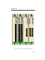
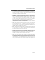
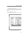
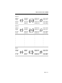
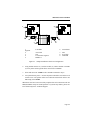
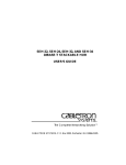
Cabletron Systems offers four versions of the 10BASE-T Twisted Pair Media Interface Module (Fig. 1-1) for connecting 10BASE-T Twisted Pair Segments to a
Multi Media Access Center (MMAC™):
•
TPMIM-22 with 12 RJ-45 ports.
•
TPMIM-24 with 24 RJ-45 ports.
•
TPMIM-32 with one 50 pin Champ connector.
•
TPMIM-34 with two 50 pin Champ connectors.
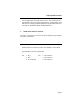
1.1 USING THIS MANUAL
Chapter 1, Introduction, discusses the capabilities and special features of
Cabletron Systems' TPMIM. This chapter also includes a list of related manuals.
Chapter 2, Installation Requirements/Specifications, contains a list of network
requirements that must be met before installing the TPMIM. The specifications
for the TPMIM are also included in this section.
Chapter 3, Installing the TPMIM, contains instructions for installing the TPMIM
into the MMAC, connecting twisted pair segments to the MIM, and connecting
10BASE-T Ethernet devices to the TPMIM.
Page 1-1
INTRODUCTION
Figure 1-1. 10BASE-T Twisted Pair Media Interface Modules
Page 1-2
INTRODUCTION
Chapter 4, Testing and Troubleshooting, provides procedures for testing and
troubleshooting the installation of the TPMIM. Instructions for using LANVIEW®, Cabletron Systems’ built-in visual diagnostic and status monitoring system, are also included.
We assume that you have a general working knowledge of Ethernet or IEEE 802.3
type data communications networks and their physical layer components.
1.2 GETTING HELP
If you need additional support related to the Cabletron Systems TPMIM, or if you
have any questions, comments or suggestions related to this manual, feel free to
contact Cabletron Systems' Technical Support at:
Cabletron Systems
35 Industrial Way
P.O. Box 5005
Rochester, NH 03867-5005
Phone: (603) 332-9400
1.3 THE 10BASE-T TWISTED PAIR MEDIA INTERFACE MODULES
Cabletron Systems' 10BASE-T Twisted Pair Media Interface Modules provide 12
or 24 ports, utilizing either RJ-45 ports or 50-pin Champ connectors. When used
with the MMAC-8/FNB™, up to 168 10BASE-T twisted pair segments can be
connected.
Distance and Cable Type
The TPMIM supports 10BASE-T Twisted Pair Segments up to 125 meters in
length. These segments can be made from a wide variety of popular unshielded
twisted pair cabling with properties varying from 75-165 ohm impedance and 2226 AWG conductor size.
Page 1-3
INTRODUCTION
Polarity Detection and Correction
Each Port on the TPMIM incorporates a Polarity Detection and Correction feature. The Polarity Detection and Correction feature allows the TPMIM to pass
data regardless of the polarity of the twisted pair segments’ receive link. If polarity is reversed, the LNK LED will flash to indicate this condition, once a good
packet passes through the port.
NOTE: If this condition exists, the segment should be removed from the TPMIM
and the wiring corrected in the event that, in the future, the segment needs to be
attached to a device without the Polarity Correction and Detection feature.
Multi Media Access Centers
The Cabletron Systems’ 10BASE-T Twisted Pair Media Interface Modules are
designed to be installed into the Cabletron Systems MMAC. The modular design
of the MMAC allows the TPMIM to
co-exist with other Media Interface Modules (MIM™s) to provide a variety of different media connections on any one point. This means that the TPMIM can be
used by itself or in conjunction with any combination of other MIMs accommodating Fiber Optic Cable, Thick or Thin Ethernet Coaxial Cabling, or AUI Cabling.
Each packet entering the TPMIM is repeated by the MMAC’s repeater module.
These include the Cabletron Systems Intelligent Repeater Module (IRM-2™) and
Intelligent Repeater Bridging Module (IRBM™). Each packet that enters the repeater module is regenerated and retimed, which assures data integrity and maximum data path distance. In addition, the repeater feature ensures fault isolation,
since the repeater module will automatically segment problem ports from the network. A segmented port will be automatically reconnected to the network once
the port has received a good packet.
Page 1-4
INTRODUCTION
The repeater module also allows you to access the network management capabilities that enable you to control the TPMIM and its attached segments. For example, information on the number of good packets and collisions that have passed
through the TPMIM and each port on the MIM can be gathered. A variety of network management programs can be used to manage the TPMIM, including:
•
•
•
•
Cabletron Systems SPECTRUM™.
Cabletron Systems Remote LANVIEW/Windows™.
Cabletron Systems Local Management.
Third party SNMP compliant network management packages.
LANVIEW LEDs
The TPMIM incorporates LANVIEW, Cabletron Systems’ built-in diagnostic and
status monitoring LED system. These LEDs, incorporated into all Cabletron Systems’ products, will assist you in rapidly diagnosing network problems as they
arise. Each port on the TPMIM has two LANVIEW LEDs: the Link OK (LNK)
LED and the Receive (RCV) LED. The Link OK LED will remain lit as long as
a link is maintained between the applicable port on the module and the 10BASET device at the other end of the cable. If a link is not established, the LED will not
be lit. The Receive LED will be lit when activity is detected on the segment.
The TPMIM also has one Collision (CLN) LED, which indicates a collision on
any segment attached to one of the ports, and one Error (ERR) LED, which indicates a potential temperature problem within the MMAC.
1.3.1The TPMIM-22/24
The TPMIM-22/24 design incorporates built-in RJ-45 ports, 12 on the TPMIM22 and 24 on the TPMIM-24. This design makes it easier to incorporate twisted
pair wiring schemes into your network. The TPMIM-22/24 allows you to directly
connect the segments to patch panels or other 10BASE-T Ethernet devices, eliminating the need for Punch-Down blocks or additional patch panels.
Each RJ-45 port on the TPMIM-22/24 is internally crossed over, eliminating the
need to cross over the twisted pair segment going from the port to the 10BASE-T
device at the other end of the segment.
Page 1-5
INTRODUCTION
1.3.2The TPMIM-32/34
The TPMIM-32/34 provides an alternative method for incorporating 10BASE-T
twisted pair segments into an existing twisted pair wiring scheme. The TPMIM32 has one 50 pin Champ connector that allows you to connect 12 segments to the
module. The
TPMIM-34 has two 50 pin Champ connector that allows you to connect 24 segments to the module. The 50 Pin Champ connector allows the MIM to tie directly
into Punch-Down blocks and patch panels. This connector complies with all
punch down and harmonica specifications.
1.4 RELATED MANUALS
The manuals listed below should be used to supplement the procedures and other
technical data provided in this manual. The procedures in them will be referenced,
where appropriate, but will not be repeated.
Cabletron Systems’ Multi-Media Access Center (MMAC-3/FNB MMAC5FNB and MMAC-8/FNB) Overview and Set Up Guide.
Cabletron Systems LAN-MD User Manual.
Page 1-6
REQUIREMENTS/SPECS.
CHAPTER 2
INSTALLATION REQUIREMENTS/SPECIFICATIONS
Before you attempt to install the Cabletron Systems 10BASE-T Twisted Pair Media Interface Modules, review the network requirements that are outlined in this
chapter. Also, refer to the operating specifications that are listed.
All conditions, guidelines, specifications, and requirements included in this chapter must be met to ensure satisfactory performance of the TPMIM. Failure to follow these guidelines may result in unsatisfactory network performance.
2.1 NETWORK REQUIREMENTS
When connecting 10BASE-T twisted pair segments to the TPMIM, you must follow the network guidelines listed below.
•
Length - The IEEE 802.3 10BASE-T standard requires that 10BASE-T
transceivers be able to transmit over a 100 meter
(328 feet) link using 24 AWG unshielded twisted pair wire.
10BASE-T specifies no maximum link length.
Due to cable delay, the maximum link length is always limited to about 200
meters (656 feet), regardless of the cable type.
As a general rule, links of up to 150 meters (492 feet) long are achievable for
unshielded and shielded twisted pair cable, with a maximum of 200 meters
(656 feet) due to cable delay. For each connector or patch panel in the link,
subtract 12 meters (39.4 feet) from the 150 meter limit. This will allow for
links of up to 126 meters (413.4 feet) using standard 24 AWG UTP wire and
two patch panels within the link. Higher quality low attenuation cables may
be required when using links greater than 126 meters.
Page 2-1
REQUIREMENTS/SPECS.
•
Insertion Loss - The maximum insertion loss allowed for a 10BASE-T link
is 11.5 dB at all frequencies between 5.0 and 10.0 MHz. This includes the
attenuation of the cables, connectors, patch panels, and reflection losses due
to impedance mismatches in the link segment.
•
Impedance - Unshielded twisted pair cables typically have an impedance of
between 85 to 110 ohms. Shielded cables, such as Type 1 cable, can also be
used. You should remember that the impedance of Type 1 cable is typically
150 ohms, as this increases the signal reflection caused by the cable. Since
the cable is shielded, signal reflection has little effect on the received signal’s
quality due to the lack of crosstalk between the shielded cable pairs.
Cabletron Systems’ 10BASE-T twisted pair products will work on shielded
twisted pair cable with 75 to 165 ohms impedance.
•
Jitter - Intersymbol interference and reflections can cause jitter in the bit cell
timing, resulting in data errors. A 10BASE-T link must not generate more
than 5.0 nsec of jitter. If your cable meets the impedance requirements for a
10BASE-T link, jitter should not be a concern.
•
Delay - The maximum propagation delay of a 10BASE-T link segment must
not exceed 1000 nsec. This 1000 nsec maximum delay limits the maximum
link segment length to no greater than 200 meters.
•
Crosstalk - Crosstalk is caused by signal coupling between the different cable pairs contained within a multi-pair cable bundle. 10BASE-T transceivers
are designed so that the user does not need to be concerned about cable
crosstalk, provided the cable meets all other requirements.
•
Noise - Noise can be caused by either crosstalk or externally induced impulses. Impulse noise may cause data errors if the impulses occur at very specific
times during data transmission. Generally, the user does not need to be concerned about noise. If noise related data errors are suspected, it may be necessary to either reroute the cable or eliminate the source of the impulse noise.
Page 2-2
REQUIREMENTS/SPECS.
•
2.2
Temperature - Multi-pair, PVC 24 AWG telephone cables have an attenuation of approximately 8 to 10 dB/100 m at 20° C. The attenuation of PVC
insulated cable varies significantly with temperature. At temperatures greater
than 40° C, we strongly recommend that you use plenum rated cables to ensure that cable attenuation remains within specification.
OPERATING SPECIFICATIONS
The operating specifications for the Cabletron Systems TPMIM are included in
this section. Cabletron Systems reserves the right to change these specifications
at any time without notice.
RJ-45 INTERFACE (TPMIM-22/24)
Internal Transceiver:Cabletron Systems’ TPT 10BASE-T Twisted Pair
Transceiver.
Type:Internally Crossed Over RJ-45 Jack
Pin
1
2
3
4
RX+
RXTX+
No Connection
Pin
5
6
7
8
No Connection
TXNo Connection
No Connection
Page 2-3
REQUIREMENTS/SPECS.
CHAMP CONNECTOR INTERFACE (TPMIM-32/34)
Type:
50 Pin Champ Connector
Pin
Signal
1
2
3
4
5
6
7
8
9
10
11
12
13
14
15
16
17
18
19
20
21
22
23
24
25
RX 1TX 1RX 2TX 2RX 3TX 3RX 4TX 4RX 5TX 5RX 6TX 6RX 7TX 7RX 8TX 8RX 9TX 9RX 10TX 10RX 11TX 11RX 12TX 12N/C
Wire Color
Blue/White
Orange/White
Green/White
Brown/White
Gray/White
Blue/Red
Orange/Red
Green/Red
Brown/Red
Gray/Red
Blue/Black
Orange/Black
Green/Black
Brown/Black
Gray/Black
Blue/Yellow
Orange/Yellow
Green/Yellow
Brown/Yellow
Gray/Yellow
Blue/Violet
Orange/Violet
Green/Violet
Brown/Violet
Gray/Violet
Pin Signal
26
27
28
29
30
31
32
33
34
35
36
37
38
39
40
41
42
43
44
45
46
47
48
49
50
RX 1+
TX 1+
RX 2+
TX 2+
RX 3+
TX 3+
RX 4+
TX 4+
RX 5+
TX 5+
RX 6+
TX 6+
RX 7+
TX 7+
RX 8+
TX 8+
RX 9+
TX 9+
RX 10+
TX 10+
RX 11+
TX 11+
RX 12+
TX 12+
N/C
Wire Color
White/Blue
White/Orange
White/Green
White/Brown
White/Gray
Red/Blue
Red/Orange
Red/Green
Red/Brown
Red/Gray
Black/Blue
Black/Orange
Black/Green
Black/Brown
Black/Gray
Yellow/Blue
Yellow/Orange
Yellow/Green
Yellow/Brown
Yellow/Gray
Violet/Blue
Violet/Orange
Violet/Green
Violet/Brown
Violet/Gray
Page 2-4
REQUIREMENTS/SPECS.
FRONT PANEL INDICATORS
CLN
(Collision Present)
of the segments
ERR (Error)
When flashing, this red indicator
indicates that a collision has occurred on one
attached to the module.
When lit, this red indicator indicates that a
potential temperature problem exists inside
the MMAC.
NOTE: There is one Link and Receive LED for each port on the module.
LNK (Link)
When lit, this green LED indicates that a link
has been established between that TPMIM
port and the 10BASE-T compliant device at
the other end of the twisted pair segment.
RCV (Receive)
When flashing or lit , this yellow LED indicates that the TPMIM is receiving a data
packet from the segment connected to the
port.
ENVIRONMENTAL REQUIREMENTS
Operating temperature:+5° to +40° C (41° to 104° F)
Non operating temperature:-30° to +80° C (-22° to 160° F)
Operating humidity:5 to 95% (non-condensing)
Page 2-5
REQUIREMENTS/SPECS.
SAFETY
WARNING: It is the responsibility of the person who sells the system to
which the TPMIM will be a part to ensure that the total system meets allowed
limits of conducted and radiated emissions.
Designed in accordance with UL478, UL910, NEC 725-2(b), CSA, IEC,
TUV, VDE Class A. Meets FCC part 15, Class A limits.
SERVICE
MTBF (MHBK-217E)
TPMIM-22
TPMIM-24
TPMIM-32
TPMIM-34
>192,159 hrs.
>107,736 hrs.
>195,350 hrs.
>108,062 hrs.
MTTR<0.5 hr.
PHYSICAL
Dimensions
34.04 D x 29.21 H x 5.08 W cm
(13.4 D x 11.5 H x 2.0 W in)
Weight
TPMIM-22/32
.658 kg (1.45 lbs)
TPMIM-24/34
1.09 kg (2.4 lbs)
Page 2-6
INSTALLING THE TPMIM
CHAPTER 3
INSTALLING THE TPMIM
This chapter contains instructions for installing the Cabletron Systems 10BASET Twisted Pair Media Interface Module (TPMIM) into any of Cabletron Systems'
MMACs. Instructions for connecting twisted pair segments to the MIM are also
included. Check that all requirements listed in Chapter 2, Installation Requirements/Specifications, are met before installing the MIM.
3.1 UNPACKING THE TPMIM
Before you install the TPMIM, you should visually inspect it.
To unpack the TPMIM:
1.
Remove the shipping material covering the module in the shipping box.
2. Carefully remove the module from the shipping box. Leave the module in
its conductive bag until you are ready to install it. Save the shipping box and materials in the event the unit has to be reshipped.
3. Visually inspect the module. If any damage appears to have occurred, contact Cabletron Systems' Technical Support immediately.
3.2 INSTALLING THE TPMIM INTO THE MMAC
The TPMIM is designed to be easily installed into any MMAC. When you install
the TPMIM, the following guidelines must be followed:
•
You cannot install the TPMIM into Slot 1, which is reserved for theRepeater Module.
Page 3-1
INSTALLING THE TPMIM
•
1.
If installing a TPMIM-24/34, an IRM-2 or an IRBM must be installed Slot
•
If the module is going to be installed into an
MMAC-8™/MMAC-8FNB™/MMAC-5FNB™, be sure a Power Supply
Module (PSM-R™, or MMAC-5PSM™) is installed in the MMAC to supply
power to the module. The MMAC-3™/MMAC-3FNB™ have a built-in power
supply.
Install the TPMIM into the MMAC as follows:
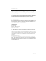
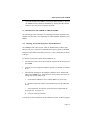
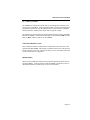
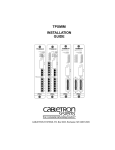
1. Slide the TPMIM (2, Fig. 3-1) into the MMAC’s (1) card cage. Be sure that
the card is in the top and bottom slots (4) of the case.
Figure 3-1. Installing a Module in the MMAC
Page 3-2
INSTALLING THE TPMIM
2.
Secure the module to the MMAC by turning the knurled knobs (3). Be sure
the TPMIM is firmly attached to the MMAC by turning the knurled knobs.
Failure to do so may result in improper operation.
3.3 CONNECTING THE TPMIM TO THE NETWORK
The following provides instructions for connecting twisted pair segments to the
TPMIM. The procedure varies depending on which TPMIM is installed in your
MMAC.
3.3.1 Attaching Twisted Pair Segments to the TPMIM-22/24
The TPMIM-22 has 12 RJ-45 ports, while the TPMIM-24 has 24 RJ-45 ports.
This provides easy connection of unshielded twisted pair segments to the MIM.
Each port on the module is internally crossed over. This is indicated by an X next
to the port.
To connect a twisted pair segment to the TPMIM-22/24:
1.
Insert the RJ-45 connector on the twisted pair segment into an RJ-45 port on
the TPMIM.
2.
At the device end of a segment, attach the segment to a 10BASE-T complaint
device.
3.
Check that the Link light on the 10BASE-T Ethernet device and the LNK
LED on the TPMIM are lit. If the LEDs are not lit, perform each of the following steps until the LEDs are lit:
a.
Check that the 10BASE-T device and the MMAC are powered up.
b. Disconnect the RJ-45 connector from the RJ-45 port on the 10BASE-T
device.
c. Verify that the RJ-45 connector on the twisted pair segment has the
proper pin outs. See Figure 3-2.
d.
Check the cable for continuity.
If a link has not been established, contact Cabletron Systems' Technical Support.
Page 3-3
INSTALLING THE TPMIM
If the Link LED is flashing, once a good packet passes through the port, this indicates that the polarity of the twisted pair segments’ receive link is reversed. If this
condition exists, the segment should be removed from the TPMIM and the wiring
corrected in the event that, in the future, the segment needs to be attached to a device without the Polarity Correction and Detection feature.
TPMIM-22/24
RJ-45 Port
Twisted Pair Segment
10BASE-T Device
End RJ-45 Port
Pin 1 - RX+
Pin 1 - TX+
Pin 2 - RX-
Pin 2 - TX-
Pin 3 - TX+
Pin 3 - RX+
Pin 4 - N/C
Pin 4 - N/C
Pin 5 - N/C
Pin 5 - N/C
Pin 6 - TX-
Pin 6 - RX-
Pin 7 - N/C
Pin 7 - N/C
Pin 8 - N/C
Pin 8 - N/C
Figure 3-2. Cable Pinouts - TPMIM-22/24
3.3.2 Attaching Twisted Pair Segments to the TPMIM-32/34
The TPMIM-32 has a 50 pin Champ connector, while the TPMIM-34 has two 50pin Champ connectors. This configuration of the TPMIM allows you to run a 50
pin feeder cable from the TPMIM to a punch down block. Each Champ connector
can accommodate 12 10BASE-T, twisted pair segments.
Page 3-4
INSTALLING THE TPMIM
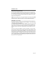
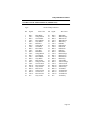
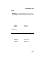
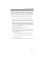
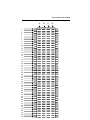
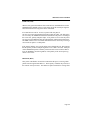
As an aid, three tables and one figure have been included with this section. Table
3-1 describes the pins and the color codes that are used in twisted wiring from the
TPMIM-32/34 and a punch down block. Table 3-2 describes the pins and the color codes that are used from a punch down block to a 10BASE-T Ethernet device.
Table 3-3 gives a summary of twisted pair wiring between a TPMIM-32/34 and a
10BASE-T Ethernet device. Figure 3-3 illustrates a labeled punch down block.
To connect the TPMIM-32/34 into an existing twisted pair wiring system:
1.
Connect a 50-pin feeder cable to the Champ connector on the TPMIM.
2.
Attach the feeder cable to the punch down block, or patch panel. If using a
TPMIM-34, a second 50-pin feeder cable can be connected to the MIM.
In most cases, the feeder cable can be connected directly to a punch down
block by a Champ connector located on the block. If not, the punch down
block must be wired using the punch down information in Table 3-1 and Figure 3-2. This table and figure describe the pins and the color codes that are
used to wire into a punch down block.
3.
At the device end of a segment, attach the segment to a
10BASE-T complaint Ethernet device.
4.
Check that the Link light on the 10BASE-T Ethernet device and the LNK
LED on the TPMIM are lit. If the LEDs are not lit, perform each of the following steps until the LEDs are lit:
a.
Check that the 10BASE-T device and the MMAC are powered up.
b.
Verify the cabling between the module and the 10BASE-T device.
c.
Check the cable for continuity.
If a link has not been established, contact Cabletron Systems' Technical Support.
Page 3-5
INSTALLING THE TPMIM
If the Link LED is flashing, once a good packet passes through the port, this indicates that the polarity of the twisted pair segments’ receive link is reversed. If this
condition exists, the segment should be removed from the TPMIM and the wiring
corrected in the event that, in the future, the segment needs to be attached to a device without the Polarity Correction and Detection feature.
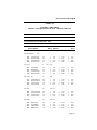
TABLE 3-1
TWISTED PAIRS WIRING
FROM A TPMIM-32/34 TO A PUNCH DOWN BLOCK
From
Into and Out of 50 Into Punchdown
TPMIM-32/34Pin Feeder CableBlock
Port 12/24Pin
RX+
RXTX+
TX-
Pin 48
Pin 23
Pin 49
Pin 24
Pin
48
23
49
24
Port 11/23Pin
Pin
RX+
RXTX+
TX-
46
21
47
22
Pin 46
Pin 21
Pin 47
Pin 22
Port 10/22Pin
Pin
RX+
RXTX+
TX-
44
19
45
20
Pin 44
Pin 19
Pin 45
Pin 20
Violet/Green
Green/Violet
Violet/Brown
Brown/Violet
RX+
RXTX+
TX-
A45
A46
A47
A48
Violet/Green
Green/Violet
Violet/Brown
Brown/Violet
RX+
RXTX+
TX-
Violet/Blue
Blue/Violet
Violet/Orange
Orange/Violet
RX+
RXTX+
TX-
A41
A42
A43
A44
Violet/Blue
Blue/Violet
Violet/Orange
Orange/Violet
RX+
RXTX+
TX-
Yellow/Brown
Brown/Yellow
Yellow/Gray
Gray/Yellow
RX+
RXTX+
TX-
A37
A38
A39
A40
Yellow/Brown
Brown/Yellow
Yellow/Gray
Gray/Yellow
RX+
RXTX+
TX-
Page 3-6
INSTALLING THE TPMIM
Port 9/21
RX+
RXTX+
TX-
Pin
Pin 42
Pin 17
Pin 43
Pin 18
Pin
42
17
43
18
Yellow/Orange
Orange/Yellow
Yellow/Green
Green/Yellow
RX+
RXTX+
TX-
A33
A34
A35
A36
Yellow/Orange
RX+
Orange/Yellow
RXYellow/GreenTX+
Green/Yellow
TX-
Page 3-7
INSTALLING THE TPMIM
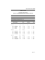
TABLE 3-1 (cont.)
TWISTED PAIRS WIRING
FROM A TPMIM-32/34 TO A PUNCH DOWN BLOCK
From
Into and Out of 50 Into Punchdown
TPMIM-32/34Pin Feeder CableBlock
Port 8/20
RX+
RXTX+
TXPort 7/19
Pin
Pin 40
Pin 15
Pin 41
Pin 16
Pin
40
15
41
16
Pin
Pin 38
Pin 13
Pin 39
Pin 14
Port 6/18
Pin
RX+
RXTX+
TX-
Pin 36
Pin 11
Pin 37
Pin 12
36
11
37
12
Pin
Pin
Pin 34
Pin 9
Pin 35
Pin 10
34
9
35
10
RX+
RXTX+
TX-
RX+
RXTX+
TX-
A29 Black/GrayRX+
A30 Gray/BlackRXA31 Yellow/BlueTX+
A32 Blue/YellowTX-
RX+
RXTX+
TX-
A25 Black/GreenRX+
A26 Green/BlackRXA27 Black/BrownTX+
A28 Brown/BlackTX-
Pin
RX+
RXTX+
TX-
Port 5/17
Black/Gray
Gray/Black
Yellow/Blue
Blue/Yellow
38
13
39
14
Black/Green
Green/Black
Black/Brown
Brown/Black
Pin
Black/Blue
Blue/Black
Black/Orange
Orange/Black
RX+
RXTX+
TX-
A21 Black/BlueRX+
A22 Blue/BlackRXA23 Black/OrangeTX+
A24 Orange/BlackTX-
Red/Brown
Brown/Red
Red/Gray
Gray/Red
RX+
RXTX+
TX-
A17 Red/BrownRX+
A18 Brown/RedRXA19 Red/GrayTX+
A20 Gray/RedTX-
Page 3-8
INSTALLING THE TPMIM
Port 4/16
RX+
RXTX+
TX-
Pin
Pin 32
Pin 7
Pin 33
Pin 8
Pin
32
7
33
8
Red/Orange
Orange/Red
Red/Green
Green/Red
RX+
RXTX+
TX-
A13 Red/OrangeRX+
A14 Orange/RedRXA15 Red/GreenTX+
A16 Green/RedTX
Page 3-9
INSTALLING THE TPMIM
TABLE 3-1 (cont.)
TWISTED PAIRS WIRING
FROM A TPMIM-32/34 TO A PUNCH DOWN BLOCK
From
Into and Out of 50 Into Punchdown
TPMIM-32/34Pin Feeder CableBlock
Port 3/15Pin
RX+
RXTX+
TX- Pin 6
Pin 30
Pin 5
Pin 31
6
Pin
30
White/Gray
5
Gray/White
31
Red/Blue
Blue/RedTX-
Port 2/14Pin
RX+
RXTX+
TX-
Pin 28
Pin 3
Pin 29
Pin 4
Pin 26
Pin 1
Pin 27
Pin 2
A9
White/Gray
A10 Gray/White
A11 Red/Blue
Blue/RedTX-
RX+
RXTX+
A5
A6
A7
A8
White/Green
Green/White
White/Brown
Brown/White
RX+
RXTX+
TX-
A1
A2
A3
A4
White/Blue
Blue/White
White/Orange
Orange/White
RX+
RXTX+
TX-
Pin
28
3
29
4
White/Green
Green/White
White/Brown
Brown/White
Port 1/13Pin
RX+
RXTX+
TX-
RX+
RXTX+
A12
RX+
RXTX+
TXPin
26
1
27
2
White/Blue
Blue/White
White/Orange
Orange/White
RX+
RXTX+
TX-
NOTE: Pins 25 and 50 on champ connector are not used.
Page 3-10
INSTALLING THE TPMIM
TABLE 3-2
TWISTED PAIRS WIRING
FROM A PUNCH DOWN BLOCK TO A 10BASE-T DEVICE
From PunchdownTo RJ-45Into Office Into
BlockWallplate
Port 12/24PinPin
B45
B46
B47
B48
Violet/Green
Green/Violet
Violet/Brown
Brown/Violet
Violet/Blue
Blue/Violet
Violet/Orange
Orange/Violet
Yellow/Brown
Brown/Yellow
Yellow/Gray
Gray/Yellow
Port 9/21
B33
B34
B35
B36
Yellow/Orange
Orange/Yellow
Yellow/Green
Green/Yellow
Port 8/20
B29
B30
B31
B32
RX+
RXTX+
TXPin
Port 10/22 Pin
B37
B38
B39
B40
Device
Pin
Port 11/23
B41
B42
B43
B44
Drop 10BASE-T
Black/Gray
Gray/Black
Yellow/Blue
Blue/Yellow
1
2
3
6
TX+
TXRX+
RX-
1
2
3
6
TX+
TXRX+
RX-
1
2
3
6
TX+
TXRX+
RX-
TX+
TXRX+
RX-
1
2
3
6
TX+
TXRX+
RX-
1
2
3
6
TX+
TXRX+
RX-
TX+
TXRX+
RX-
1
2
3
6
TX+
TXRX+
RX-
1
2
3
6
TX+
TXRX+
RX-
1
2
3
6
TX+
TXRX+
RX-
1
2
3
6
TX+
TXRX+
RX-
1
2
3
6
TX+
TXRX+
RX-
1
2
3
6
TX+
TXRX+
RX-
Pin Pin
RX+
RXTX+
TX-
1
2
3
6
Pin
Pin
RX+
RXTX+
TX-
1
2
3
6
Pin
Pin Pin
RX+
RXTX+
TX-
1
2
3
6
Pin
Pin Pin
RX+
RXTX+
TX-
1
2
3
6
TX+
TXRX+
RX-
TX+
TXRX+
RX-
Page 3-11
INSTALLING THE TPMIM
TABLE 3-2 (cont.)
TWISTED PAIRS WIRING
FROM A PUNCH DOWN BLOCK TO A 10BASE-T DEVICE
From PunchdownTo RJ-45Into Office Into
BlockWallplate
Port 7/19
B25
B26
B27
B28
Pin
Black/Green
Green/Black
Black/Brown
Brown/Black
Port 6/18
B21
B22
B23
B24
Black/Blue
Blue/Black
Black/Orange
Orange/Black
RX+
RXTX+
TXPin
Red/Brown
Brown/Red
Red/Gray
Gray/Red
Port 4/16
B13
B14
B15
B16
RX+
RXTX+
TXPin
Port 5/17
B17
B18
B19
B20
Drop 10BASE-T
RX+
RXTX+
TXPin
Red/Orange
Orange/Red
Red/Green
Green/Red
RX+
RXTX+
TX-
Pin
1
2
3
6
Pin
TX+
TXRX+
RXPin
1
2
3
6
TX+
TXRX+
RX-
TX+
TXRX+
RX-
1
2
3
6
TX+
TXRX+
RX-
1
2
3
6
TX+
TXRX+
RX-
1
2
3
6
TX+
TXRX+
RX-
TX+
TXRX+
RX-
1
2
3
6
TX+
TXRX+
RX-
TX+
TXRX+
RX-
1
2
2
6
TX+
TXTXRX-
Pin
TX+
TXRX+
RX-
Pin
1
2
3
6
1
2
3
6
Pin
Pin
1
2
3
6
Device
1
2
3
6
Pin
TX+
TXRX+
RX-
1
2
3
6
Page 3-12
INSTALLING THE TPMIM
TABLE 3-2 (cont.)
TWISTED PAIRS WIRING
FROM A PUNCH DOWN BLOCK TO A 10BASE-T DEVICE
From PunchdownTo RJ-45Into Office Into
BlockWallplate
Port 3/15
B9
B10
B11
B12
Pin
White/Gray
Gray/White
Red/Blue
Blue/Red
Port 2/14
B5
B6
B7
B8
White/Green
Green/White
White/Brown
Brown/White
Port 1/13
B1
B2
B3
B4
Drop
White/Blue
Blue/White
White/Orange
Orange/White
Pin
10BASE-T
Device
Pin
RX+
RXTX+
TX-
1
2
3
6
TX+
TXRX+
RX-
Pin
Pin Pin
RX+
RXTX+
TX-
1
2
3
6
Pin
Pin Pin
RX+
RXTX+
TX-
1
2
3
6
TX+
TXRX+
RX-
TX+
TXRX+
RX-
1
2
3
6
TX+
TXRX+
RX-
1
2
3
6
TX+
TXRX+
RX-
1
2
3
6
TX+
TXRX+
RX-
1
2
3
6
TX+
TXRX+
RX-
1
2
3
6
TX+
TXRX+
RX-
1
2
3
6
TX+
TXRX+
RX-
Page 3-13
INSTALLING THE TPMIM
TABLE 3-3
TWISTED PAIR WIRING SUMMARY
TPMIM 32/34Punch DownWall Plate
10BASE-T
ChampBlock
Ethernet
(If Required)
Device
Page 3-14
INSTALLING THE TPMIM
Port 12
A45 RX+
A46 RXA47 TX+
A48 TX-
{
{
{
49 TX+
24 TX-
{
25 Pin
Feeder
Cable
4 Pair
Twisted
Distribution
Cable
PIN 1 TX+
PIN 2 TX-
{
PIN 3 RX+
PIN 6 RX+
{
48 RX+
23 RX-
Office
Drop
PIN 1 TX+
PIN 2 TXPIN 3 RX+
PIN 6 RX+
Port 11
{
{
A41 RX+
A42 RXA43 TX+
A44 TX-
{
{
47 TX+
22 TX-
25 Pin
Feeder
Cable
4 Pair
Twisted
Distribution
Cable
:
:
:
:
:
:
:
:
:
:
:
:
:
:
:
:
:
:
:
:
:
:
PIN 1 TX+
PIN 2 TX-
{
PIN 3 RX+
PIN 6 RX-
{
46 RX+
21 RX-
Office
Drop
PIN 1 TX+
PIN 2 TXPIN 3 RX+
PIN 6 RX-
:
:
:
:
:
:
:
:
:
:
:
:
:
:
:
:
:
:
:
:
:
:
PIN 1 TX+
PIN 2 TX-
PIN 1 TX+
PIN 2 TX-
Port 1
{
25 Pin
Feeder
Cable
A3 TX+
A4 TX-
{
{
27 TX+
2 TX-
{
A1 RX+
A2 RX-
4 Pair
Twisted
Distribution
Cable
{
PIN 3 RX+
PIN 6 RX-
{
26 RX+
1 RX-
Office
Drop
PIN 3 RX+
PIN 6 RX-
Page 3-15
INSTALLING THE TPMIM
A
1
2
3
4
5
6
7
8
9
10
11
12
13
14
15
16
17
18
19
20
21
22
23
24
25
26
27
28
29
30
31
32
33
34
35
36
37
38
39
40
41
42
43
44
45
46
47
48
49
B
C
D
Page 3-17
TESTING AND LANVIEW
CHAPTER 4
TESTING AND LANVIEW
This section contains procedures to ensure that the connection between the TPMIM and the 10BASE-T Ethernet device is functioning properly. A description
of LANVIEW and its function in troubleshooting physical layer network problems is also provided.
4.1
INSTALLATION CHECK-OUT
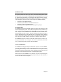
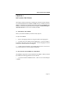
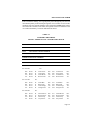
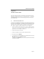
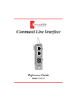
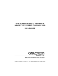
You should test the TPMIM after installation to ensure that the physical layer of
the network is operating properly. Two Ethernet node testers that generate valid
data packets, such as Cabletron Systems' LAN-MD, are required for this procedure. Figure 4-1 illustrates a sample installation check-out configuration.
1.
Connect a 10BASE-T twisted pair transceiver, such as a Cabletron Systems
TPT (3, Fig. 4-1), to the device end of the twisted pair segment connected to
applicable port on the TPMIM in an MMAC (5).
2.
Connect an AUI cable (2) to the TPT.
3.
Connect a LAN-MD (1) to the AUI cable connected to the TPT.
4.
Select and run test 6 - SERVER.
5.
Verify that the the Test Status PASS LED is lit and that the Status Code reads
000 or 001. If these two conditions are met, the
LAN-MD is now the SERVER unit and will act as a packet echoer when used
with another LAN-MD.
Page 4-1
TESTING AND LANVIEW
9
1
2
3
8
4
6
5
1.
Segment
2.
3.
4.
5.
7
LAN-MD
6.
Twisted Pair
AUI Cable
TPT
Twisted Pair Segment
MMAC-8
7.
8.
9.
TPT
AUI Cable
LAN-MD
Figure 4-1. Sample Installation Check-Out Configuration
6.
Using another transceiver (7) and AUI cable (8), connect another LAN-MD
(9) to any other tested segment that is connected to an MMAC.
7.
Select and run test 4 - NODE on the LAN-MD connected in step 6.
8.
Verify that this test passes. At least 100 packets should be sent and received
with no errors. The packets will be received from and sent back to the LANMD acting as the NODE.
When these tests have been successfully completed for each connection to the TPMIM, the MIM is ready for normal operation. If you note any failures, please contact Cabletron Systems’ Technical Support.
Page 4-2
TESTING AND LANVIEW
4.2 USING LANVIEW
The TPMIM uses Cabletron Systems built-in visual diagnostic and status monitoring system, LANVIEW. Using LANVIEW LEDs, your network troubleshooting personnel can quickly scan the LEDs to observe network status or diagnose
network problems, and determine which node or segment is faulty.
The following section discusses the function and the purpose of each LANVIEW
LED on the TPMIM. You should note that there is one Link OK (LNK) and one
Receive (RCV) LED for each port on the TPMIM.
COLLISION DETECT (CLN)
This red indicator flashes to indicate that a collision has occurred on one of the
segments attached TPMIM. The frequency of flashes may increase as the network
activity increases, since more collisions are likely to occur. The flash of the LED
is pulse-stretched for viewing effect.
ERROR (ERR)
When lit, this red indicator indicates that a potential temperature problem exists
inside the MMAC. If the temperature inside the MMAC remains above the recommended temperature, failures may occur in network traffic.
Page 4-3
TESTING AND LANVIEW
LINK OK (LNK)
When lit, this green LED indicates that a link has been established between the
TPMIM and the 10BASE-T device at the other end of the twisted pair segment.
This LED remains lit as long as the link is maintained.
If no data has been sent for 16 msec, a positive link test pulse of
100 nsec is sent onto the transmit link of the twisted pair cable. The link pulses
are received by the TPMIM and checked to determine if the pulse is occurring at
the correct rate, polarity and pulse shape. If no pulses are received or the pulses
are not correct, the MIM will enter the Link Fail State, and the LED will not be lit.
The MIM will not receive or transmit data until the link is restored by receiving a
correct link test pulse or a valid packet.
If the LED is flashing, once a good packet passes through the port, this indicates
that the polarity of the twisted pair segments’ receive link is reversed. Each port
on the TPMIM incorporates a Polarity Detection and Correction feature that allows the TPMIM to pass data regardless of the polarity of the twisted pair segments’ receive link.
RECEIVE (RCV)
This yellow LED flashes on and off to indicate that the port is receiving a data
packet from the segment attached to it. The frequency of flashes may increase as
the network activity increases. The flashes are pulse-stretched for viewing effect.
Page 4-4