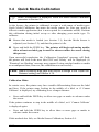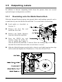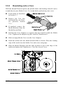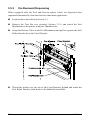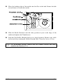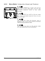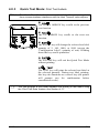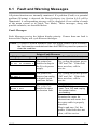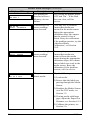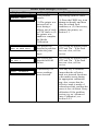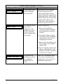
1
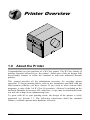
Operator’s Manual Corporate Headquarters 4501 Parkway Commerce Blvd. Orlando, Fl 32808 Phone: 407-578-8007 Fax: 407-578-8377 Asia-Pacific 19 Loyang Way #01-01 CILC Building Singapore 508724 Phone: +65 542-2611 Fax: +65 542-3611 Datamax International Herbert House 12 Elizabeth Way, Pinnacles Harlow, Essex CM19 5FE UK Phone: +44 1279 772200 Fax: +44 1279 424448 Copyright Information: CG Triumvirate is a trademark of Agfa Corporation. CG Times, based upon Times New Roman, is under license from The Monotype Corporation. Firmware (Software) Agreement The enclosed Firmware (Software) resident in the Printer is owned by Licensor or its suppliers and is licensed for used only on a single printer in the user’s Trade or Business. The User agrees not to, and not to authorize or permit any other person or party to, duplicate or copy the Firmware or the information contained in the non-volatile or programmable memory. The firmware (Software) is protected by applicable copyright laws and Licensor retains all rights not expressly granted. In no event will Licensor or its suppliers be liable for any damages or loss, including direct, incidental, economic, special, or consequential damages, arising out of the use or inability to use the Firmware (Software). Information in this document is subject to change without notice and does not represent a commitment on the part of Datamax Barcode Products Corporation. No part of this manual may be reproduced or transmitted in any form or by any means, for any purpose other than the purchaser's personal use, without the expressed written permission of Datamax Corporation. © Copyright 2001 by Datamax Corporation All rights reserved. Printed in the United States of America. Part Number: 88-2245-01 Revision: E Agency Compliance and Approvals: UL1950 Information Technology Equipment C22.2 No. 950-M93 C Listed US EN60950 For 230 Volt Operation (Europe): Use a cord set, marked “HAR,” consisting of a min H05VV-F cord which has a minimum 0.75 square mm diameter conductors, provided with an IEC 320 receptacle and a male plug for the country of installation rated 6A, 250V Für 230 Volt (Europa): Benützen Sie ein Kabel, das mit “HAR” markiert ist, bestehend mindestens aus einem H05VV-F Kabel, das mindestens 0,75 Quadratmillimeter Drahtdurchmesser hat; sowie eine IEC320 Steckdose und einen für das Land geeigneten Stecker, 6A, 250 Volt. As an Energy Star Partner, the manufacturer has determined that this product meets the Energy Star guidelines for energy efficiency. The manufacturer declares under sole responsibility that this product conforms to the following standards or other normative documents: EMC: EN 55022 (1993) Class B EN 50024 (1998) EN 45501 (1992) Safety:This product complies with the requirements of EN 60950 /A11: /1997 Gost-R FCC This device complies with FCC CFR 47 Part 15 Class A. ã Note: This equipment has been tested and found to comply with the limits for a Class A digital device, pursuant to Part 15 of the FCC Rules. These limits are designed to provide reasonable protection against harmful interference when the equipment is operated in a commercial environment. This equipment generates, uses, and can radiate radio frequency energy, and if not installed and used in accordance with the instructions in this manual, it may cause harmful interference to radio communications. Operation of this equipment in a residential area is likely to cause harmful interference in which case the user will be required to correct the interference at his own expense. Important Safety Instructions: The exclamation point within an equilateral triangle is intended to alert the user to the presence of important operating and maintenance instructions in the literature accompanying this unit. This unit has been carefully designed to provide years of safe, reliable performance. However, as with all electrical equipment, there are some basic precautions that you follow to avoid personal injury or damage to the printer: ½ Before using the printer, carefully read all the installation and operating instructions. ½ Observe all warning instruction labels on the printer. ½ Install the printer on a flat, firm surface. ½ Do not place the printer on or near a heat source. ½ To protect your printer from overheating, make sure no openings on the printer are blocked. ½ Never insert anything into the ventilation slots and openings of the printer. ½ Do not use the printer near water or spill liquid into it. ½ Ensure that the AC power source matches the ratings listed for the printer. (If unsure, check with your dealer or local utility provider.) ½ Do not place the AC power cord where it can be stepped on. If the AC power cord becomes damaged or frayed, replace it immediately. ½ If the printer ever needs repair, consult only qualified, trained service personnel. No user-serviceable parts are inside; do not remove the cover. &RQWHQWV Printer Overview 1.0 1.1 About the Printer ................................................................. 1 1.0.1 Standard Features ................................................ 2 1.0.2 Optional Features ................................................ 2 Option Installation................................................................ 4 Getting Started 2.0 2.1 Unpacking the Printer .......................................................... 5 Media and Ribbon Selection................................................ 7 2.1.1 Print Quality Controls ............................................ 7 Setting Up the Printer 3.0 3.1 3.2 3.3 3.4 3.5 Installation ........................................................................... 9 3.0.1 Communications ................................................. 10 Loading Media................................................................... 12 3.1.1 Roll Media........................................................... 13 3.1.2 Fan-Fold Media................................................... 14 Media Sensor Adjustment ................................................. 15 Loading Ribbon ................................................................. 16 Quick Media Calibration .................................................... 17 Outputting Labels .............................................................. 18 3.5.1 Rewinding onto the Media Rewind Hub .............. 18 3.5.2 Rewinding onto a Core ....................................... 19 3.5.3 On-Demand Dispensing...................................... 20 Using the Front Panel 4.0 Operation .......................................................................... 23 4.0.1 Ready Mode ....................................................... 23 4.0.2 Menu Mode......................................................... 24 4.0.3 Quick Test Mode................................................. 25 4.0.4 Indicator Lights ................................................... 26 4.0.5 LCD .................................................................... 26 4.0.6 Resetting the Printer ........................................... 27 i 4.1 4.2 4.3 4.0.6.1 Soft Reset ............................................ 27 4.0.6.2 Level One Reset................................... 27 4.0.6.3 Level Two Reset................................... 27 The Menu System ............................................................. 28 4.1.1 Entrance and Exit Prompts ................................. 29 4.1.2 Media Settings .................................................... 30 4.1.3 Print Control........................................................ 31 4.1.4 Printer Options.................................................... 33 4.1.5 System Settings .................................................. 35 4.1.6 Communications ................................................. 41 4.1.7 Diagnostics ......................................................... 47 Display Messages ............................................................. 48 4.2.1 User Prompts and Condition Messages .............. 48 Quick Test Mode ............................................................... 50 4.3.1 Print Quality Label............................................... 50 4.3.2 Configuration Label............................................. 51 4.3.3 Quick Ribbon Test Label..................................... 52 4.3.4 Dot Test Pattern Label ........................................ 53 4.3.5 Validation Label .................................................. 54 4.3.6 User Defined Label ............................................. 54 Adjusting and Maintaining the Printer 5.0 5.1 5.2 5.3 5.4 Media Sensor Calibration .................................................. 55 5.0.1 Standard Calibration ........................................... 55 5.0.2 Advanced Entry Calibration................................. 59 Printhead Adjustments ...................................................... 65 5.1.1 Leveling Cam Adjustment ................................... 65 5.1.2 Pressure Adjustment........................................... 66 Maintenance Schedule ...................................................... 67 5.2.1 Cleaning the Printhead ....................................... 68 5.2.2 Cleaning the Platen Roller .................................. 69 5.2.3 Cleaning Interior and Exterior Surfaces............... 70 Application Program Updates ............................................ 70 5.3.1 Updating from the Ready Mode .......................... 71 5.3.2 Updating from the Download Mode ..................... 72 5.3.3 Possible Problems during an Update .................. 73 Boot Loader Program Updates .......................................... 74 ii Troubleshooting 6.0 6.1 6.2 Problem Resolution ........................................................... 75 Fault and Warning Messages ............................................ 79 Hex Dump Mode ............................................................... 85 Printer Specifications 7.0 7.1 General Specifications....................................................... 87 Media and Ribbon Requirements ...................................... 89 Appendix A ASCII Control Code Chart .......................................................... 91 Appendix B Available Fonts and Bar Codes.................................................. 93 Appendix C Module Assignments................................................................ 101 Print Resolutions and Maximum Label Widths ......................... 101 Available Speeds and Default Settings .................................... 102 Appendix D GPIO Port ................................................................................ 103 Appendix E Menu System Multi-Language Support .................................... 105 Appendix F Saving a Configuration File ...................................................... 111 iii Warranty Information ................................................... 113 Glossary ............................................................................. 117 Index ..................................................................................... 121 iv 3ULQWHU2YHUYLHZ 1.0 About the Printer Congratulations on your purchase of a W-Class printer. The W-Class family of printers, hereafter referred to as ‘the printer’, blend state of the art design with user-friendly features to refine the standard in wide-web industrial thermal printers. This manual provides all the information necessary for everyday printer operation. To begin printing labels, refer to the instructions provided with the label-creation software you have chosen. If you wish to write custom label programs, a copy of the I & W Class Programmer’s Manual is included on the enclosed Datamax Accessories CD; otherwise, a copy may be downloaded from our web site at http//www.datamaxcorp.com. To grow with all of your printing needs, the design of the printer is easily upgraded; see Section 1.1. The following subsections detail the standard features, available options and a hardware overview. W-Class 1 1.0.1 Standard Features This printer offers the following standard features: Printing ½ ½ ½ ½ ½ ½ Direct and Thermal Transfer printing methods Batch and Pause Mode Printing 1.5 inch or 3 inch Media Hub (specified at time of order) Easy Media Loading Media Tear Bar Fan-fold media compatible Memory ½ ½ ½ 256 KB Flash Memory available for user graphic downloads 2 MB FLASH Downloadable Program Memory 16 MB SDRAM Memory Interfaces ½ ½ IEEE 1284 compliant parallel interface RS-232 serial interface Operational ½ ½ ½ ½ ½ 2 X 20 Backlit Liquid Crystal Display and functional keypad CG Triumvirate Scalable font w/AGFA Scalable font engine EFIGS (multi-language display and configuration label support) 203 DPI Printhead (W-6208) 300 DPI Printhead (W-6308 and W-8306) 1.0.2 Optional Features The printer offers the following optional features: Cover Dampener A device to control the closing rate of the cover. Light-Duty Cutter (unavailable for the W-8306) Easily installed on the front of the printer, this rotary mechanism will cut a maximum material thickness of .006” (.152mm) into minimum lengths of 1.25 inches (31.8 mm). 2 W-Class Standard Cutter Easily installed on the front of the printer, this guillotine mechanism will cut a maximum material thickness .010” (.254mm) into minimum lengths of 1.25 inches (31.8 mm). Cutter Tray Used to collect the media cut by the Standard or Light-Duty Cutter (specify application at time of order). External Keyboard Support An interface for the connection of the DMX Passport™ keyboard, allowing remote (no host) printing applications. External Media Rewinder Separate device with and 8” roll capacity to rewind labels and backing material. Font Expansion Card (cannot be used with the I/O Expansion card) A slide-in circuit card assembly with 8MB Flash memory expansion for International Language Printing Capability (ILPC) and/or additional fonts and graphics. ILPC consists of one of the following: ½ ½ ½ ½ CG-Times (Western European) Scalable font Kanji Gothic B Scalable font Simplified Chinese GB Scalable font Korean Hangul Scalable font ILPC – CG Times Firmware The printer’s firmware can be upgraded to include the Datamax ILPC CG Times font. This supports the Datamax Enhanced Language Code Pages. Internal Rewind (factory installed) A mechanism to rewind printed labels and backing material inside the printer. I/O Expansion Card (specify features at time of order) Standard features of this slide-in circuit card assembly include: ½ ½ General purpose (GPIO) interface for external printer and device control. Time and date calendar (Real Time Clock) function for label time stamping. Additional option: ½ 8 MB Flash memory expansion for graphics and/or additional fonts including International Language Printing Capability (ILPC). W-Class 3 LAN Interface A slide-in circuit card assembly that provides network connectivity, allowing multiple users on various platforms to share the same printer. Peel and Present Mechanism (requires the Internal Rewind option) A device used to automatically separate printed labels from the backing material. When accompanied by the present sensor option, on-demand label dispensing becomes possible. Present Sensor A sensor used to control the printer output. When enabled, printing occurs after the removal of a previously print label. RS-422 Serial Interface A single-drop interface to support greater distances from the host at communication rates of up to 38,400 baud. Twinax/Coax Interface (including cable) These are internal devices, providing connection to AS/400 and System/3X Twinax host system or 3270-type host system. 1.1 Option Installation This table lists the recommended qualification level for the person installing the options. Contact your dealer or Datamax Technical Support for details. Suggested Experience Level Option Cover Dampener Cutter Tray Cutters: Standard and Light-Duty DMX Passport External Keyboard Font Expansion Card Internal Rewind International Language Programming Capability I/O Expansion Card LAN Interface Peel Mechanism Present Sensor RS-422 Serial Interface Twinax/Coax Interface 4 Qualified Installer DMX Certified Technician Operator DMX Certified Technician Operator DMX Certified Technician DMX Certified Technician DMX Certified Technician DMX Certified Technician DMX Certified Technician Operator DMX Certified Technician DMX Certified Technician DMX Certified Technician W-Class *HWWLQJ6WDUWHG 2.0 Unpacking the Printer Inspect the shipping container(s) for damage; if evident, immediately notify the shipping company to report the nature and extent of the damage. The printer has been carefully packaged to avoid damage during transit. In order to operate the printer, you will need to remove the tape and foam placed there for shipment. Complete the following steps prior to connecting power or attempting to load media. å With the arrows on the box pointing ‘Up’, open the box. Remove packing foam. ê Using the straps, carefully lift the printer from the box. Remove the straps and the plastic bag from the printer. ã Note: It is a good idea to save the carton and packaging materials. W-Class 5 Inspecting the Printer After removing the printer from the packaging material, check the contents of the package. In addition to this manual, the following items should be included: ½ Printer ½ Power cord ½ Accessories CD ½ Any special or additionally purchased items. Additional Requirements The following items are necessary for generating printed labels. Contact your customer support representative for advice on which media and software is best suited for your needs. ½ A serial or parallel interface cable; see Section 3.0.1 ½ Applicable media; see Section 2.1 for suggestions and Section 7.1 for requirements. ½ Applicable labeling software 6 W-Class 2.1 Media and Ribbon Selection The following is a limited overview of media characteristics. For complete information and advice regarding your specific application needs, always consult a qualified media specialist or a Datamax Media Representative. Media Selection – Direct Thermal Consider three important factors when selecting direct thermal stock: • The abrasive qualities of the material that covers the thermal reactive layer of the paper. • The ability of that layer to control the chemical reaction that occurs when the image is “burned”. • The amount of heat required to create an image on the paper. Media Selection – Thermal Transfer Consider three important factors when selecting thermal transfer media combinations: • The label top coating and ribbon combinations affect image quality. • Ribbon backcoating is highly recommended. It provides protection for the printhead; and depending upon the formula, it may also provide an antistatic coating. • For additional printhead protection, use ribbon with a slightly greater width than the overall width of the label and backing material. 2.1.1 Print Quality Controls The printer provides flexibility with a comprehensive set of print controls. Of these, the amount of heat applied by the printhead and the rate of media movement will have the most effect on the barcodes, text, and graphics being printed. Low cost direct thermal stocks, for example, have raised reaction temperatures and therefore require higher heat values and slower print speeds to make a clear image on the media. In general, there are four methods of controlling print quality: • The first is the ‘Media Type’ menu setting, which should be set to match the media being used. For example, when printing with ribbon use the thermal transfer setting. W-Class 7 • The second method would be to change the ‘Print Control / Heat’ menu setting (selectable as ‘Heat Setting’ in most software programs). Increasing this value causes more energy to be transferred to the media, resulting in a darker image. If the image is too dark, reduce this value or increase the print speed. • The next method would be to change the ‘Print Control / Print Speed’ menu setting (also selectable as ‘Print Speed’ in most software programs). Changing the print speed changes the amount of time the media is under the printhead. Slowing the speed allows more time and control for energy to be transferred. Increasing the speed will increase throughput, but may require a higher heat setting. • The final method, providing only subtle contrast changes, would be to change the ‘Custom Adjustments / Darkness’ menu setting. You will find that printing barcodes and detailed images on less expensive direct thermal and thermal transfer media at higher speeds can be tricky. At one heat setting, the images will fade and at the next higher heat setting, the images will bleed. This is because the reaction temperature of the media is so high that at higher rates of speed, it cannot react fast enough. To print fine images at higher speed, media with lower reaction or release temperatures are required. On the slower end of the print rate settings, crisper images are possible because the media is not being stretched beyond its limits. The following table is intended for reference only (for specific application information, consult your media specialist or a Datamax Media Representative). Thermal Transfer Media Coated Paper, Uncoated Paper, Tag Stock, Some Films, Some Synthetics Coated Paper, Glossy Paper, Tag Stock, Some Synthetics, Films Synthetics, Films Ribbon Type Wax Print Speed* 2-8 Print Image Energy Durability Low Low Wax/Resin 2-8 Medium High Resin 4-6 High High *Values given in inches per second (IPS) 8 W-Class 6HWWLQJ8SWKH3ULQWHU 3.0 Installation This chapter explains how to connect your printer, and load it with media and ribbon. ã Note: When connecting the AC Power Cord or data cables to the printer, ensure the Power On/Off Switch is in the ‘Off’ position. å Place the printer on a firm, level surface. Turn ‘Off’ the Host Computer and ensure that the Power Switch on the Printer is in the ‘Off’ position. ê Depending upon your interfacing requirements, connect the appropriate interface cable between Host Computer and Printer; see Section 3.0.1. (If connecting the printer to a network, refer to the additional documentation supplied with the network option.) Connect the AC power cord to the receptacle on the back of the Printer, and then plug the AC power cord into a properly grounded outlet. (The power supply in the printer automatically detects, then adjusts to the applied line voltage; see Section 7.0 for acceptable voltage ranges.) W-Class 9 3.0.1 Communications Using a data detection process, the interface selection occurs automatically in the printer. At power-up, the printer begins monitoring the interface ports for activity. When the host transmits data, the printer port detecting this data is set ‘active’ and remains active as long as data flow continues. Once the incoming (received) data flow stops and the Host Timeout Value (see Section 4.1.6) is exceeded, the detection process will be repeated. In addition, should the data flow stop before a complete label format is received, the format will be ignored and must be sent to the printer again. ã Note: To change an active port immediately, cycle the printer power ‘Off’ and ‘On’. Parallel Port: The parallel interface has two menu-selectable modes of operation: unidirectional or bi-directional. Uni-directional mode is forward channel communication and requires a Centronics cable with a 36 pin male connector. Bi-directional mode is IEEE 1284 Compliant, using forward and reverse channel communications. In this mode, data can be sent to the host provided it is also IEEE 1284 Compliant and has supporting software. This mode requires an IEEE 1284 cable with a Centronics 36 pin male connector. NIC Adapter (optional): The NIC Adapter has several menu-selectable modes; see Section 4.1.6 for details. Refer to the information provided with the option for connection requirements. The following items are accessible from the back of the printer: • The LED Indicators provide operational information: A green LINK LED indicates a good network connection. A green 100 LED indicates a 100BASE-T network connection. The ACT LED (activity) flashes green or red when the server is ready for use. • The Test Button will cause a NIC Configuration label to print. • The Ethernet Reset button will reset the NIC Adapter. ã Note: Following initialization, the printer will indicate ‘Ready’; however, the NIC Adapter will not be ready to receive data until its ‘boot-up’ process is completed. Depending upon the NIC Adapter configuration, this process may take up to two minutes to complete. 10 W-Class Serial Port: The serial interface supports RS-232C and, if equipped, RS-422 communications. The following list of serial port settings is menu-selectable and must match the host computer’s serial port settings; see Section 4.1.6. • • • • • Baud Rate (serial communication speed) Word Length Word Parity Number of Stop Bits Handshaking Protocol In addition to the port settings, the serial interface cable wiring must have specific connections (pin-outs) for proper data exchange between the host and printer. The different serial cable pin-outs, suggested applications, and part numbers are shown below (contact your reseller for ordering information). Serial Interface Cable Listing (all models, except as noted) Null Modem (MXM) “PC” (DB9P) to Printer Part Number 556000 Part Number 556001 For connection to other DCE equipment. Flow control is only Xon/Xoff. “PC” (DB25P) to Printer Part Number 556002 For connection to a PC compatible with DB25 communication ports. Flow control can be either Xon/Xoff or CTS/DTR. W-Class For connection to a PC compatible with DB9P communication ports. Flow control can be either Xon/Xoff or CTS/DTR. RS-422 Connection* Part Number N/A Diagram is provided only as a reference. 11 3.1 Loading Media The following section explains the media loading steps. Before beginning, complete these steps: å Raise the Access Cover. Rotate the Printhead Latch forward to raise the Printhead Assembly. ê Slide the Media Guide out away from the frame. Proceed according to the type of media you are using: go to Section 3.1.1 for Roll Media or go to Section 3.1.2 for FanFold Media. 12 W-Class 3.1.1 Roll Media This loading method is for roll type media applications. To load: å Slide Roll Media onto the Media Supply Hub until it rests against the Backstop. Route the media as shown below: under the Bouncer Assembly, through the Media Sensor, then out the front of the printer. ê Slide the Media Guide over until it rests lightly against the edge of the media. Position the Media Sensor; see Section 3.2. If your application uses thermal transfer media, load ribbon (see Section 3.3); otherwise continue. ñ Lower the Printhead Assembly and rotate the Printhead Latch completely back into the locked position. Close the Access Cover. ò Turn ‘On’ the printer. After ‘Ready is displayed, press and hold the FEED key until at least one label gap or mark is advanced; see Section 3.4. ☞ If using less than full width media, adjust the Leveling Cam; see Section 5.1.1. W-Class 13 3.1.2 Fan-Fold Media This loading method is for tag and fan-fold type media applications. To load: å Bring media in from the Bottom or Rear Fan-Fold Slot and through the printer, as shown below. (If using reflective stock, ensure that the mark is facedown.) Slide the Media Guide over until it rests lightly against the edge of the media. ê With the Roller Lever in its ‘down’ position, slide the Fan-Fold Media Guide onto the Media Supply Hub and route the media through the slot in the guide. Ensure the media rests against the Backstop, then raise the Roller Lever to its ‘up’ position and tighten the Thumbscrew on the bottom of the Fan-Fold Media Guide. Position the Media Sensor; see Section 3.2. If your application uses thermal transfer media, load ribbon (see Section 3.3); otherwise continue. ñ Lower the printhead assembly and rotate the Printhead Latch back into the locked position. Close the Access Cover. ò Turn ‘On’ the printer. After ‘Ready is displayed, press and hold the FEED key until at least one label gap or mark is advanced; see Section 3.4. ☞ 14 If using less than full width media, adjust the Leveling Cam; see Section 5.1.1. W-Class 3.2 Media Sensor Adjustment The Media Sensor needs to be positioned so that the printer can detect the presence of media and the top-of-form (except for continuous stock, where the TOF is set through programming; see Label Length, Section 4.1.2). To adjust: å With media loaded, as described in Section 3.1.1 or 3.1.2, turn the Media Sensor Adjust Knob clockwise (outward) or counterclockwise (inward) until the Sensor Eye Mark is positioned over the media according to the table below. If loading media, return to the media loading instructions. Media Type Die-cut Notched Reflective Continuous Media Sensor Selection and Adjustment Sensor Required* Sensor Eye Mark Position Near the middle of the label Gap Centered over the notch Gap Centered over the black mark Reflective Near the middle of the media Continuous * See Section 4.1.2 for Sensor Type selection. ã Note: Changes to the start of print position can be made using the Print Control / Row Adjust or Row Offset (see Section 4.1.3). W-Class 15 3.3 Loading Ribbon Thermal transfer media requires the use of ribbon. To load: ã Note: Using a ribbon that is slightly wider than your media (and liner, if any) will help protect against printhead wear. å With the access cover raised, remove the J-Hook from the Ribbon Take-Up Hub. Position the Ribbon as shown below and then slide it completely onto the Ribbon Supply Hub. ê Raise the Printhead Assembly, pull approximately eighteen inches (450mm) of ribbon from the roll and route it under the Lower Ribbon Roller then out over the Platen Roller, as shown. Lower the Printhead Assembly, route the ribbon over the Upper Ribbon Rollers and down around the Ribbon Take-up Hub. Replace the J-Hook on the Ribbon Takeup Hub. While holding the hub, rotate the J-Hook counterclockwise to latch it. Rotate the hub counterclockwise to remove any slack from the ribbon. ñ If loading media, return to the media loading instructions. Otherwise, lower the Printhead Assembly and rotate the Printhead Latch completely back into the locked position. Close the Access Cover. 16 W-Class 3.4 ☞ Quick Media Calibration When ‘Uncalibrated’ is displayed, follow the Media Sensor Calibration procedure in Section 5.0. At the factory, the printer is calibrated to sense a wide range of media types. Quick Media Calibration fine-tunes the media sensor for your gap, notch or reflective media application (this is not required for continuous media). Perform this calibration during initial set-up or after changing your media type. To calibrate: å Ensure that media is loaded (see Section 3.1), that the Media Sensor is adjusted (see Section 3.2), and that the printer is idle. Press and hold the FEED key. The printer will begin advancing media; allow at least one label gap or mark to advance under the sensor during this process. Upon successful completion, the ‘Calibration Completed’ message will flash; the printer will feed to the next label TOF and ‘Ready’ will be displayed. (A ‘Warning Low Backing’ message may appear if using notched media or media on a transparent liner; however, the calibration was successful). ã Note: Media containing large gaps may require a change in the ‘Paper Out Distance’ setting; see Section 4.1.2. Calibration Hints: In certain cases, the printer may have trouble differentiating between the label and liner. If the printer stops feeding in the middle of a label or if ‘Cannot Calibrate’ is displayed, try calibrating over a longer distance: • Press and hold the FEED key to allow two gaps or marks to advance under the sensor. If the printer continues to stop in the middle of a label, or if ‘Cannot Calibrate’ is displayed again: • Press and hold the FEED key to allow three or more gaps or marks to advance under the sensor. If this method also fails, see Media Sensor Calibration, Section 5.0.