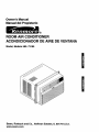
1
Owner's Manual
Manual del Propietario
®
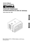
ROOM AIR CONDITIONER
ACONDICIONADOR DE AIRE DE VENTANA
Model, Modelo 580. 73189
Sears, Roebuck and Co., Hoffman
www.sears.com
Estates, IL 60179 U.S.A.
TABLE
OF CONTENTS
WARRANTY
SAFETY
Features .................................................
........................ 2
..............................................
2
.....................................................
3
10
Using the Air Conditioner ....................... 10
Display ...................................................
11
Remote Control ......................................
12
ImportantSafety Instructions...................... 3
ELECTRICAL
INSTALLING
REQUIREMENTS
THE
POWER
MAINTENANCE
....... 4
CORD
.--.4
.....................................
13
Air Filter Cleaning ...................................
13
Air Conditioner Cleaning ........................ 13
INSTALLATION
........................................
5
How to Remove the Front Grille.................. 13
Installation Requirements ......................... 5
Installation ................................................
How to Replacethe Front Grille.................. 13
6
TROUBLESHOOTING
......................... 14
How to Install ....................... _.................... 6
Before Calling for Service ...................... 14
Removalfrom Window................................. 8
OPERATION
.............................................
9
How and Why ...........................................
9
Normal Sounds ........................................
9
ESPANOL
15
MASTER PROTECTION
AGREEMENTS
......................................31
Capacity and Running Time ..................... 9
FULL ONE YEAR WARRANTY
ROOM AIR CONDITIONER
................................................
SERVICE
NUMBERS
............BackCover
WARRANTY SERVICE IS AVAILABLE BY
CONTACTING SEARS SERVICE AT
1-800-4-MY-HOME ®.
ON
For one year from the date of purchase, when this
air conditioner is operated and maintained for
normal room cooling according to instructions in this
owner's manual, Sears will repair this air
conditioner, free of charge, if defective in material or
workmanship.
Warranty coverage applies only to air conditioners
used for non-commercial, private household
purposes.
This warranty applies only while this product is in
use in the United States.
FULL FIVE-YEAR WARRANTY ON
SEALED REFRIGERATION SYSTEM
This warranty gives you specific legal rights, and
you may also have other right which vary from state
to state.
For five years from the date of purchase, when this
air conditioner is operated and maintained for
normal room cooling according to instructions in this
owner's manual, Sears will repair the sealed
refrigeration system (consisting of refrigerant,
connecting tubing, and compressor), free of charge,
if defective in material or workmanship.
-2-
Sears, Roebuck and Co., D/817WA,
Hoffman Estates, IL 60179 U.S.A.
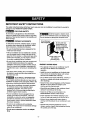
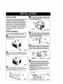
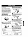
IMPORTANT SAFETY INSTRUCTIONS
The safety instructionsbelow willtell you how to useyour room air conditionerto avoidharm to yourselfor
damage to yourROOM AIR CONDITIONER.
FOR YOUR SAFETY
Do not store or use gasoline or other flammable
vapors and liquids in the vicinity of this or any other
appliance. Read product labels for flammability and
other warnings.
PREVENT
_
Avoidfire hazard or electric shock.
Do not use an extension cordor an adapterplug.
Do not removeany prongfrom the powercord.
Groundingtype
wall receptacle
ACCIDENTS
To reduce the risk of fire, electrical shook, or injury
to persons when using your air conditioner, follow
basic precautions, including the following:
• Be sure the electrical service is adequate for the
model you have chosen.
• If the air conditioner is to be installed in a window,
you wil! probably want to clean both sides of the
glass first. If the window is a triple-treck type with a
screen panel included, you may want to remove
the screen completely before installation.
Power supply cord
with 3-prong
grounding plug
• Be sure the air conditioner has been securely and
correctly installed according to the separate
installation instructions provided with this manual.
Save this manual and installation instructions for
possible future use in removing or reinstalling this
unit.
ENERGY SAVING IDEAS
• The capacity of the room air conditioner must fit
the room size for efficient and satisfactory
operation.
• Use gloves when handling the air conditioner.
Be careful to avoid cuts from sharp metal fins on
front and rear coils.
ELECTRICAL
Do not underany
circumstancescut,
remove,or bypass
the groundingprong
from this plug.
• Install the room air conditioner on the shady side
of your home. A window that faces nodh is best
because it is shaded most of the day.
• Do not block air flow inside with blinds, curtains, or
furniture, or outside with shrubs, enclosures, or
other buildings.
INFORMATION
The complete electrical rating of your new room air
conditioner is stated on the serial plate. Refer to the
rating when checking the electrical requirements.
• Close the floor and wall registers and the fireplace
damper so cool air does not escape up the
chimney and into the duct work.
• Be sure the air conditioner is properly grounded.
To minimize shock and fire hazards, proper
grounding is important. The power cord is
equipped with a three-preng grounding plug for
protection against shock hazards.
• Keep blinds and drapes in other windows closed
during the sunniest part of the day.
• Clean the air filter as recommended in the
MAINTENANCE section of this manual.
• Your air conditioner must be plugged into in a
properly grounded wall receptacle. If the wall
receptacle you intend to use is not adequately
grounded or protected by a time delay fuse or
circuit breaker, have a qualified electrician install
the proper receptacle.
• Proper insulation and weather stripping in your
home will help keep warm air out and cool air in.
• External house shading with trees, plants or
awnings will help reduce the air conditioner's work
load.
• Do not run air conditioner with a protective
covering. This could result in mechanical damage
within the air conditioner.
• Operate heat producing appliances such as
ranges, washers, dryers, and dishwashers during
the coolest part of the day.
• Do not use an extension cord or an adapter
plug.
-3-
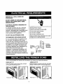
OBSERVE ALL LOCAL CODES AND
ORDINANCES.
DO NOT, UNDER ANY CIRCUMSTANCES,
REMOVE THE POWER SUPPLY CORD
GROUND PRONG.
ELECTRICAL GROUND IS REQUIRED ON
THIS APPLIANCE.
For 230/208 volt 60 Hz, AC only, 15A fused
and properly grounded electrical supply is
required. A time delay fuse or time delay circuit
breaker is recommended. Use a dedicated
Electrical Shock Hazard
circuit, serving only this appliance.
Do not use an adapter.
Do not use an extension cord.
Plug into a grounded 3 prong outlet.
Do not remove ground prong.
DO NOT USE AN EXTENSION CORD.
RECOMMENDED
GROUNDING
Failure to follow these instructions can result
in death, fire, or electrical shock.
METHOD
For your personal safety, this appliance must
be grounded. This appliance has a power
supply cord with a 3-prong grounding plug. To
minimize possible shock hazard, the cord must
be plugged into a mating grounding type wall
receptacle and grounded in accordance with
the National Electrical Code (ANSI/NFPA 70)
latest edition and all local codes and
ordinances. If a mating wall receptacle is not
available, it is the personal responsibility and
obligation of the customer to have a properly
grounded 3-prong wall receptacle installed by a
qualified electrician.
_3-pron._
3
ron
-P
It_
.g._
g[ounelng i__>
IL" JLLI
)yFI
Power _
supply
cord
I
I1__" _, I
grounding
type wall
receptacle
L_ Ground
prong
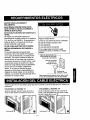
You can choose between two methods below according to your window stool shape and preference.
USING
USING SLIT "B"
SLIT "A"
Fasten the stopper using left screwhole, and rotate
properly to lead the powercordout throughslit "B",
Fasten the stopper using 2 screw holes, and lead
out the power cord through slit "A",
O
-4-
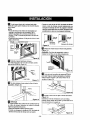
INSTALLATION REQUIREMENTS
INSTALLATION
Your air conditioner will install into standard double
hung windows with actual clear opening widths of
29 to 41 inches (737mm to 1041mm) (FIG. 1)
HARDWARE
A
B
Lower sash must open sufficiently to allow a clear
vertical opening of 18 inches (457mm). Side louvers
and the rear of the air conditioner must have clear
air space to allow enough airflow through the
condenser for heat removal. The rear of the unit
must be outdoors, not inside a building or garage.
__,,_
F
C
G
D
H
E
I
J
K
Sash
4 2,"to,,"-!I
L
M
18" rain.
I I
•,
t
Innersill I I _Wnnaow
/
FOffset
FIG. 2
_,,7
I.,,_,'
/
"-J
L."
Interiorwail "-----"
ELECTRICAL
Exterior
FIG. 1
ITEM
SERVICE
Check your available electrical service. The power
supply available must be the same as that shown on
the unit nameplate (found on right side of cabinet).
All models are equipped with a 3-prong service plug
to provide proper service and safe positive
grounding. Do not change plug in any way. Do not
use an adapter plug. If your present wall outlet does
not match your plug, call a qualified electrician to
make the necessary corrections.
SAVE CARTON and this OWNER'S MANUAL for
future reference. The carton is the best way to store
unit during winter or when not in use.
To avoid riskof personal injury, property damage,
or product damage due to the weight of this
device and sharp edges that maybe exposed:
• Air conditioners coveredin this manual pose an
excessive weight hazard. Two or more people
are needed to move and install the unit.
To prevent injuryor strain, use proper liftingand
carrying techniques when moving unit.
• Carefully inspectlocation where air conditioner
will be installed. Be sure it will support the
weight of the unit over an extended period of
time.
• Handle air conditioner with care. Wear
protective gloveswhenever lifting or carrying the
unit. AVOID the sharp metal fins of front and
rear coils.
• Make sure air conditioner does not fall during
installation.
NAME OF PARTS
Q'TY
A
SIDE CURTAIN
2
B
SUPPORT
2
C
SILL BRACKET
2
D
LOCK NUT
4
E
SCREW: 25/64"
11
BRACKET
F
SCREW: 13116
"
7
G
SCREW: 9/16"
5
H
M-SCREW
2
I
CARRIAGE BOLT
2
J
FOAM SEAL
t
K
FOAM STRIP
1
L
WINDOW LOCKING BRACKET
t
M
DRAIN PIPE
1
REQUIRED TOOLS:
• Tight Fitting gloves
• Standard screwdriver
• Phillips screwdriver
• Pliers
• Sharp knife
• 3/8-inch open end wrench or adjustable wrench
• 1/4-inch hex socket and ratcher
• Tape measure
• Electric drill
• 1/4-inch drill bit
-5-
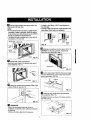
INSTALLATION
D Insert the side curtain(ITEM A) intothe upperguide
and lower guideof the air conditioner.Fasten the curtains
to the unit with screws (ITEM E).
Pick a location which will allow you to blow the cold
air into the area you want. Windows used for
installation must be strong enough to support the
weight of the air conditioner. Good installation with
special attention to the proper position of the unit
will lessen the chance that service will be needed.
When cooling more than one room. installation
location is very important. To cool your rooms, cold
air must be blown from the air conditioner in a
straight path.
Lower€
iTEM E
FIG. 6
HOW TO INSTALL
_"_ Open the window.Mark a line on the center of the
windowinnersill. Loosely attach the siUbracket(ITEM C)
to the support bracket (ITEM B) using the carriage bolt
(ITEM I) and the lock nut (ITEM D).
If the air conditioner is blocked by a stormwindowframe,
see step 16 on page 8 before beginning to install.
B
Remove the screws which fasten the cabinet at
the back and side of the unit. Save slde screws.
Discard back screws.
ITEM I
"P.
r_ Attach the sill bracket to the window sill usingthe
screws (ITEM F). Carefully place the cabinet on the
window inner sill and align the center of the cabinet
front with the center line marked on the window inner
sill.
Cabinet_
trackhole
_"_ Slide the unit out of the cabinet by gripping the
base pan handle and pull forward while bracing the
cabinet.
windowsill
Carriagebolt
and10cknut
Sillbracket
FIG. 8
_-_ Using the M-screw (ITEM H) and the lock nut
(ITEM D), attach the support bracket to the cabinet
track hole. Use the first track hole after the sill bracket
on the outer edge of the window sill. Tighten the
carriage bolt and the lock nut. Be sure the cabinet
slants downward 1/4" from level.
FIG. 4
_lcut
Lndlocknut
Outer
the FOAM SEAL (ITEM J) to fit the
CAUTION: Do not drill a hole in the bottom pan. The
unit is designed to operate with approximately 1/2" of
water in bottom pan.
underside of the window sash. Peel off the backing
and attach the FOAM SEAL as shown in Fig. 5.
Lower
guide
\
Cabinet
FIG. 5
OUTDOOR
-6-
FIG. 9
I_
Pull the bottom window sash down behind the
• Connect a drain elbow of 9/16" inside diameter to
the drain pipe.
• Connect a drain hose of 9/16" inside diameter to the
drain elbow. (Drain hose is not supplied,)
upper guide until they meet.
NOTE:
• Do not pullthe window sash down so tightlythat the
movement of sliders is restricted.Attach the cabinet
to the window inner sill by drivingthe screws (ITEM F)
throughthe cabinet into window inner sill.
• The cabinet should be installed with a very slight tilt
downward by 1/4" from level.
pE)
rain
Drain
Window sash
hose
FIG. 13
_
Slide the air conditioner into the cabinet. (FIG. 14)
CAUTION: For security purposes, reinstall side
screws that were removed in step t.
ITEM F FIG. 10
I_
Screw_
Expand side curtains to fill opening.
Attach each side cudain to the window sash using 4
screws (ITEM G). (FIG. 11)
PowerCord _----
Screw
FIG. 14
iTEM G
B
Cut the foam stdpl (ITEM K) to the proper length
and insert between the upper window sash and the
lower window sash. (FIG. 15)
FIG. 11
_11_Attach the window locking bracket (ITEM L) with
a screw (ITEM G). See FIG. 12.
FIG, 15
ITEM G
_
Adjust the vent handle before the decorative
front is attached. (FIG. 16)
Straighten the lever, as shown. Pull down part ® to
align with part (_.
FIG. 12
in
DRAINAGE
A drain hole is provided at the rear of the air
conditioner unit. Select a drain method according to
the following.
• Remove the hole rubber from the base-pan.
FIG. 16
-7-
B
FRONT INSTALLATION
Top of wood stripshould be approximately3/4"
higher than the storm window frame to help
condensation to drain properly to the outside.
Install the front grille(packed separately) onto the
cabinet as follows:
• Install a second wood strip (approximately 6" long by
lf/2" wide and same thickness as first strip) in the
center of the outer sill flush against the back of the
inner silt. Screw the L brackets into this strip.
This will raise the L bracket as shown in FIG. 20.
• Hook upper tabs of front grins into slots on the
cabinet top. (FIG. 17)
• Push front grille's tips towards the cabinet in order
to snap side tabs into the cabinet. (FIG, 17)
• Open the inlet grille, (FIG. 18)
• Install the screw (ITEM E) through the front grille.
(FIG. 18)
• Close inlet grille. (FIG. 19)
1 1/2" rnin.
(38ram)
WOOD STRIP MOUNTED
ON TOP OF INNER SILL
INNER
E_
_
3/4"
FRAME
WINDOW
FIG. 20
REMOVAL
Front Installation
FIG. 17
• Turn off and unplugthe air conditioner.
• Remove the frontgrille. See HOW TO REMOVE THE
FRONT GRILLE. Refer to page 13.
• Unscrew the side screws that you installed in Step 15.
• Slide the air conditioner out of the cabinet.
BE CAREFUL NOT TO DROP IT. Hold onto itfirmly the
whole way sliding it out. Once removed, set it safety out
of the way.
• Remove the L bracket from windowframe and the sash
seal from between the windows.
• Unscrew the side curtains from the window frame. Fold
them back to the sides of the cabinet.
ITEM E -
Front Installation
FROM WINDOW
FIG. 18
• Remove screws attaching cabinet to inner sill. Be careful
not to let cabinet fall once screws are removed.
• Remove cabinetfrom windowopening.
• Place air conditioner into cabinet. Reinstall side screws
and Front Grille.
• Place unit and all assembly hardware in air conditioner
shipping carton, and store in clean, dry place.
Front Installation
FIG. 19
I_IF
AIR CONDITIONER IS BLOCKED BY
STORM WINDOW FRAME
• If storm window presents interference, fasten a 2"
wide wood strip to the inner window sill across the full
width of the sill, The wood stripshould be thick
enough to raise the height of the window sill so that
the unit can be installedwithout interference from the
the stormwindow frame. See FIG. 20,
-8-
• Air conditioners covered in this manual pose an
excessive weight hazard. Two or more people
are needed to move and install the unit.
To prevent injury or strain, use proper lifting and
carrying techniques when moving unit.
• When handling the air conditioner, be careful to
avoid cuts from sharp metal fins on front and
rear coils.
• Make sure air conditioner does not fall during
removal.
HOW AND WHY
Your room air conditioner provides the following
functions to make hot weather living more
comfortable:
i
• Cools and circulates room air.
ompressor
The modem high efficienc,!
compressor may have a high
pitched hum or pulsating
• Lowers humidity by removing excess moisture.
noise that cycles on andoff,
• Filters out summertime dust, dirt, and some
airborne impurities.
-- Unit Vibration
The air conditioner performs these functions by
drawing room air through a filter which traps dust
and dirt particles. The air then passes over a
cooling coil which refrigerates the air and removes
excess moisture. The same air is then returned to
the room- cooler, drier, and cleaner. Moisture
removed from the room air is carried to the outside
and evaporated.
The unit may vibrate
and make noise
because of poor wall
or window construction.
Fan
You may hear air
movement from
the fan.
Your air conditioner is designed to be easy to
operate and to provide plenty of cooling power.
NORMAL
SOUNDS
FIG.21
Aside from the regular fan motor and compressor
sounds coming from your air conditioner, you will
once in a while hear a pinging sound. This is the
result of moisture being picked up from the air in the
room and thrown against the air conditioner's fan.
This is normal and should not be cause for concern.
Also, do not be alarmed if you hear a slight hissing
or gurgling sound coming from your air conditioner
after it is off. These are normal coolant noises.
You may hear droplets of water hitting
the condenser causing a pinging or
clicking sound.
FIG. 21
CAPACITY AND RUNNING TIME
Proper unit size is important in deciding the desired
comfort for the area you want to cool. An
undersized unit will not have the capability to cool,
leaving the area uncomfortably warm. The proper
size is determined by the number of square feet in
the area to be cooled, indoor and outdoor
temperature and humidity.
Whenever the heat or humidity load is above normal
the air conditioner must run longer and more often
to keep the desired temperature you have selected,
Under heavy heat load conditions the air conditioner
may need to run constantly to keep the temperature
you want.
At times using the MED FAN setting to circulate the
room air may make it comfortable even though the
air is not being cooled. This will decrease your cost
of use.
-9-
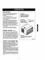
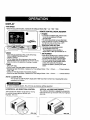
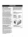
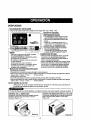
USING THE AIR CONDITIONER
FEATURES
To reduce the risk of fire, electric
shock, or injury to persons, read the important
SAFETY instructions section before operating this
appliance
To begin operating the air conditioner after
installation, follow these steps:
1. Plug in the air conditioner. (To prevent electrical
hazards, do not use an extension cord or an
adapter plug.)
2. Set the exhaust vent to the CLOSE position.
3. Set the TEMP Control to the coolest setting.
4. Set the MODE control at the highest COOL level.
5. Adjust the louvers for comfor_.ble air flow.
1
15
6
5
-4
6. Once the room has cooled, adjust the TEMP and
Mode Control to the setting you find most
comfortable.
32714
NOTE : If the air conditioner is turned off, wait 3
minutes before restarting. This allows pressure
inside the compressor to equalize. Failure to wait 3
minutes before restarting may cause inefficient
operation.
If you move the TEMP Control to a warmer, then
immediately back to a cooler setting, the unit will
shut off. Wait 3 minutes before restarting.
i
18
179
8
11
1210
13
16
VENT CONTROL
The Vent Control allows the air conditioner to
either recirculate inside air (CLOSE) or exhaust
air to the outside (OPEN). (FIG. 23)
• The CLOSE position is used when maximum
cooling is desired. It may also be used for air
recirculation without cooling when the air
conditioner is set in the FAN position.
• The OPEN position removes stale air from the
room and exhausts it to the outside• Fresh air is
drawn into the room through your home's
normal air passages.
• The OPEN or CLOSE position can be used with
any fan selection.
FIG. 22
1. Cabinet
2. Vertical Air
Direction Louvers
3. Horizontal Air
Direction Louvers
4. Inlet Grille
5. Air Filter
6. Front Grille
7. Control Board
8. Power Cord
9.
10.
11.
12.
13.
14.
15.
16.
17.
18.
Evaporator Coil
Condenser
Compressor
Base pan
Brace
Upper Guide
Curtain
Remote Control
Air Purifying Filter
Case, Filter
PULL
OPEN
/ PUSH
CLOSE
FIG. 23
-10-
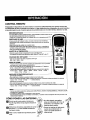
DISPLAY
- FAN SPEED
• Every time you push this button, it advances the settingas follows:{High-, Low -, Med -, High}
REMOTE CONTROL SIGNAL RECEIVER
POWER
• To turnthe airconditionerON, pushthe button.
To turnthe airconditionerOFF, push
the buttonagain.
• This buttontakespriorityoverany otherbutton.
• When youfirstturn it on, the air conditioneris on
the High coolmode and the Temp. at 72°F.
,_E'n'ING
• This buttoncan automaticallycontrol
the temperatureof the room,
The temperaturecan be set within a
range of 60°F to 86°F by incrementsof I°F.
"L_ AIR PURIFIER
- Every time you push this button, it will shift among
COOL, ENERGY SAVER and FAN.
- ENERGY SAVER:
• The fan stops when the compressor stops cooling.
I
Approximately every 3 minutes the fan will turn on and
check the room air to determine if cooling is needed.
_- TIMER
- SHUT-OFF TiME
• If unit is running, Timer sets number of hours until shut-off.
• Everytime you push Timer button, it advances the Timersettingas
- STARTTIME
• If unit is off, Timer sets number of hours before unit starts.
• Everytime you push Timer button, it advances the Timer settingas
NOTE:
CLEAN
• Press the Air Purifier button. Operation will start
at lowspeed when the button is pressed
and stop when the button is pressed again.
• Set the fan speed with the remote control.
• You can select Air Purifier function without
cooling. Fan speed will at first be low.
Increase fan speed by pressing Fan Speed
button.
follows: 1 Hour • 2 Hours ......
12 Hoursmaximum.
follows: 1 Hour , 2 Hours ...... _ 12 Hoursmaximum.
FILTER
You can see "CLEAN FILTER" display after 1000 hours that it is the time of cleaning filter when
operating in Air purifier.
1
_ower,
HORIZONTAL
the unit runs as previous
AIR DIRECTION
CONTROL
operation.
J
VERTICAL AIR DIRECTION CONTROL
The vertical air direction is adjusted by moving the
The horizontal air direction is adjusted by moving
the vertical louvers right and left with your
fingertips. (FIG. 24)
FIG.
setting
horizontal louvers up and down with your fingertips.
(FIG. 25)
24
FIG. 25
-11 -
REMOTE CONTROL
NOTE: The Remote Control will not operate properly if strong light shines on the sensor window
Conditioner or if there are obstacles between the Remote Control and the Air Conditioner.
Eve_
of the Air
time you push button, you will hear a beep from the Air Conditioner.
POWER
• Toturnthe airconditioner
ON,pushthebutton.To turn theair conditioner
OFF,
pushthe buttonagain.Thisbuttontakespriorityoveranyotherbutton.
Whenyoufirstturnit on,the air conditioner
ison theHighcoolmodeandtheTemp.at72°F
AIR PURIFIER
• Press the Air Pudfier button.Operabon will start at low speed when the buttonis pressed
and stopwhen the button is pressedagain.
• Set the fan speed with the remotecontrol.
• You can select Air Pudfier functionwithoutcooling. Fan speed will at first be low.
Increasefan speed by pressing Fan Speed button.
TEMPERATURE
SE'I'rlNG
• Thisbuttoncanautomaticallycontrol
the temperature
oftheroom,
Thetemperature
can besatwithina rangeof60°Fto86°F byincrements
ofI°F.
FAN SPEED
• Everytimeyoupushthisbuttonitadvancesthesettingas follows:
{High _Low_ Med_ High}
SLEEP MODE
• Pressthe Sleepbuttontoset thetimeyouwanttheunittoturnoffautomatically.
• Foryourspeepingcomfort,onceTimerisset,theTemperature
settingwillraiseby2"F
after30 rain. and2"Fafteranother30 rain.
• Every time you push thisbutton,the remaining time will be set as follows.
(1Hour _ 2Hours _ 3Hours _ 4Hours _ 5Hours _ 6Hours _ 7Hours _ 0Hours
tHour _ 2Houra --_...)
TIMER
- SHUT-OFF TIME
• ff unitis running, Timer sets numberof hoursuntil shut-off,
• Every timeyou push Timer button,it advances the Timer setting as follows:1 Hour--, 2 Hours _ ..-. _ 12 Hoursmaximum.
- START TIME
• If unit is off, Timer sets numberof hoursbefore unitstarts.
• Every time youpush Timer button,it advances the Timer settingas follows:1 Hour_ 2 Hours_ ..... _ 12 Hoursmaximum,
MODE
- Every timeyou push thisbutton,it will shift among COOL, ENERGY SAVER and FAN.
- ENERGY SAVER
• The fan stopswhen the compressorstopscooling.
Approximatelyevery 3 minutesthe fan will turn on and check the roomair to determineif coolingis needed.
A
HOW TO INSERT BATTERIES
L1
• Do not use rechargeable
batteries. Such batteries
Remove the cover from the back of the
remote controller.
Ip'_ Insert two batteries.
• Be sure that the (+) and (-) directions
are correct.
• Be sure that both batteries are new.
[]Re-attach
differ from standard
dry cells in
shape, dimensions,
performance.
and
• Remove
the batteries
-12-
|
from the
remote controller if the air
conditioner is not going to be
used for an extended length of
time.
the cover.
__
41_,_
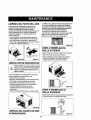
AIR FILTER CLEANING
The cabinet may be washed with mild soap or
detergent and lukewarm water, then polished with
liquid appliance wax.
The Air Filter will become dirty as it removes dust
from the inside air. It should be washed at least
every 2 weeks. If the Air Filter remains full of dust,
the air flow will decrease and the cooling capacity
will be reduced, possibly damaging the unit.
To ensure continued peak efficiency, the condenser
coils (outdoor side at the unit) should be checked
periodically and cleaned if they become clogged
with soot or dirt from the atmosphere. Brush or
vacuum exterior coils to remove debris from fins.
• Pull the inlet grille forward, grasping both tabs,
then pull out the air filter. (FIG. 26)
• Wash the Air Filter under the faucet with warm
water. Be sure to shake off all the water before
replacing the filter. (FIG.27)
FIG. 29
HOWTO REMOVETHE FRONTGRILLE
• Open the inlet grille downward.
• Remove the screw securing the Front Gdlle.
FIG. 26
• Push the grille up from the bottom and pull the top
of the grille away from the case to lift the top tabs
out of their slots.
FIG. 27
AIR PURIFYING FILTER CLEANING
,,_
shock,do nottouchAir PurifyingFilterwithin
CAUTION:To
avoid possible
minorelectric I
10 secondsafteropening
inletgrille.
The Air Purifying filter behind the air filtershouldbe
checked andcleaned once every 3 monthsor more often
if necessary.
• After removing the air filter, pullAir Purifyingfilter
slightlyforward to remove.
• Dip the Air Pudfyingfilter into water mixed with neutral
detergent,for 20.-,30minutes.
• The Air PurifyingFiltermust be completely dry before
reinstallingit intothe Air Conditioner.
• Re-installthe Air Purifying filter to the originalposition.
Inlet Grille
i_
Fr°nt
Gnlk_
o 1_
FIG. 30
HOW TO REPLACE THE
FRONT GRILLE
Attach the front grille to the cabinet by inserting the
tabs on the grille into the slots on the front of the
cabinet. Push the grille in until it snaps into place.
FIG. 28
AIR CONDITIONER
CLEANING
Clean the front grille and inlet grille by wiping with a
cloth dampened in a mild detergent
solution.(FIG.29)
FIG. 31
-13-
BEFORE CALLING FOR SERVICE
Check the following list to be sure a service call is really necessary, A quick reference to this manual may
help you avoid an unneeded service call.
THE AIR CONDITIONER WILL NOT OPERATE
Check if...
Then,..
Walt plug disconnected.
Housefuse blownor circuitbreakertripped.
Poweris OFF.
Pushpl_ firmlyintowalloutlet.
Replacefuse withtimedelay type or resetcircuitbreaker.
Pushthe powerbutton.
Unitwasturnedoff andthen on tooquickly.
TEMPCordrolset warmerthan roomtemperature.
Set unit off andwait3 minutesbeforerestarting.
SetTEMPControlto lowertemperature.
AIR FROM UNIT DOES NOT FEEL COLD ENOUGH.
Check if...
Then..,
FANSPEEDsetatLOW.
TEMPCont_ setfeewarm.
Roomtemperature
below70"F(2!"C)
Temperature
sensing
tubetouching
evape_ator
coil,
located
behindfrontgrille.
THEAIR_ER
Check if...
PushFAN SPEEDbuttonto set at HI.
Set TEMPControlto a lowertemperature.
Coolingmay not occurunfilroomtemperaturerisesabove70"F (21'C).
Straightentube awayfrom evaporatorcoil.
COOLING,
BUTROOMISTOOWAI_ - ICEFORMING
ONCOOUNG
COILBEHINDFRONT
GRILLE.
Then...
Outdoortemperature
below70°F (21°C).
To defrostthecoil,set the MODEto FAN.
Airfilter may be dirty.
Cleanair filter.Referto Maintenancesectionof owner'smanual.
TEMPControlsettoo coldfornight-timecooling.
Todefrostthecoil,setthe MODEto FAN or "HighCoor'withthe
TEMPcontrolto hiqhertemperature.
"rI.EAIRCONDmoNERCOOUNG,BUTROOMISTO0WARM.
Check if...
Then...
Dirtyairfilter- airrestricted.
TEMPControlsettoowarm.
Freerof unit is blockedby drapes,blinds,furniture,etc.
Air distribution
is restricted.
Clean air filter.RefertoMaintenancesectionof owner'smanual.
Set TEMPControlto lowertemperature.
Clear blockagein freerof unit.
Doors,windows,registers,etc.open. Coldair escapes.
Unit recentlyturnedon inhot room.
Closedoors,windows,rngistars,eta
Allowadditional
timetoremovestoPed
heatfromwalls,ceiling,
f_, andfurniture
THE AIR CONDITIONER
Check if.,.
TURNS
ON AND OFF RAPIDLY.
Then,,,
I Outsideternperature
is extremelybet'
! Set FANSPEEDonHI tobringairpestcoolingc°ils faster"
NOISE WHEN UNIT IS COOLING.
Check if...
I
Then,..
I W
Soundoffanhittingwaterfmrnthemoisturerernovalsystem.Thisis
andregisters.]
ndowvibration- poor thsta]latlen.
Referto_rmaLwhenhumidityishigh.Clesedoors,wthdows,
installationinstructionsor check withinstaller,
j
WATER DRIPPING
Check if,..
INSIDE
ROOM WHEN UNIT IS COOLING.
Then.,.
I Theairconditlonerisimproperiyinstalled
WATER DRIPPING
Check if...
OUTSIDE
WHEN
The unitis removinglargequantitiesof moisture
from humidroom.
j _tailaCOnondiitiOtnrerSl_ht(lYrtOhthecekOwUtS_i=densttOl_/_wwaterdrainage.
Referto1
UNIT IS COOLING.
Then,..
This is normalduringexcessivelyhumiddays.
-14-
INDICE DE MATERIAS ............................. 15
Caracterfsticas
.....................................
23
Uso del equipo de aire acondicionado-23
GARANT|A ................................................
15
SEGURIDAD ..............................................
16
Despliegue ............................................
Control remoto .......................................
MANTENIMIENTO
Importantesinstruccionesde seguridad..... 16
24
24
.................................... 26
Limpieza del filtro del aire ...................... 26
REQUERIMIENTOS
......... 17
Limpiezadel equipode aire acondicionado
....26
INSTALAClON DEL CABLE ELI_CTRICA ... 17
C6mo sacar la rejilla frontal ................... 26
C6mo a reernplaza el grille anterior ...... 26
INSTALACl6N
ELECTRICOS
...........................................
18
CORRECCION
Requerimientos para instalaci6n .......... 18
Installaci6n ............................................ 19
DE FALLAS ...................... 27
Antesde Llamarpara Sewicio...................... 27
C6mo instalarlo ....................... ,-............. 19
ACUERDOS DE PROTECCl6N
La eliminaci6n de la ventana ................. 21
ESPECIALIZADA
OPERACION ..............................................
22
......................................
31
PARA PEDIR SERVICIO ..--Cubierta Trasera
C6mo y por qu_ ..................................... 22
Sonidos normales .................................. 22
Capacidad y tiempo de funcionarniento...22
GARANTJA DE UN ANO POR EL
EQUIPO DE AIRE ACONDICIONADO
DE HABITACI6N
Durante un afio completo a partir de la fecha de
compra, si este equipo de aire acondicionado recibe
mantenimiento y se utiliza para el enfdamiento
normal de habitaci6n seg0n las instrucciones
indicadas en este manual del propietario, Sears
reparard gratuitamente este equipo de aire
acondicionado, si tiene algen defecto en materiales
o fabricaci6n.
GARANT[A TOTAL DE CINCO AltOS
POR EL SISTEMA DE REFRIGERACI(_N
HERMETICAMENTE SELLADO
si tiene alg0n defecto en materiales o fabdcaci6n.
EL SERVIClO DE GARANT|A ES
DISPONIBLE CONTACTANDO AL SERVICIO
SEARS AL 1-800-4-MY-HOME ®
La proteccion de garantia cubre unicamente a
los equipos de aire acondicionado usados para
uso domestioo y no para uso comercial.
Esta garantfa s61o tiene validez mientras el
producto se est6 usando en los Estados
Unidos.
Esta garantia le da derechos legales
especfficos y usted puede tener otros
derechos que varfan de estado en estado.
Durante cinco aries a partir de la fecha de compra,
si este equipo de aire acondicionado recibe
mantenimiento y se utiliza para el enfriamiento
normal de habitaci6n segL_nlas instrucciones
indicadas en este manual del propietario, Sears
reparar& gratuitamente el sistema de refrtgeraci6n
herm6ticamente sellado (que consiste en el agente
refrigerante, los tubos de conexi6n y el compresor),
Sears, Roebuck and Co., D/817WA,
Hoffman Estates, IL 60179 U.S.A.
-15-
IMPORTANTES INSTRUCCIONES DE SEGURIDAD
Las siguientes instrucciones de seguridad le indicardn c6mo usar su equipo de airs acondieionedo de
habitacibn para evitar dafios para usted mismo y papa su EQUIPO DE AIRE ACONDICIONADO.
POR SU SEGURIDAD
No almacene ni use gasolina u otros vapores y
I(quidos inflamables cerca de dste o cualquier OtTO
electrodom_stico. Lea las etiquetas de los
productos para ver si contienen advertencias sobre
et cardcter inflamable de los mismos y otras
advertencias.
Evite los peligrosde incendiosy
descargasslL_ricas. No use un cable de extensi6nni un
enchufeadaptador.Noelimineningunade las espigas
delenchufedelcord6nde alimentaci6nel_trica.
PARA PREVENIR
ACCIDENTES
Pare reducir el riesgo de incendios, descargas
el_ctdcas o lesiones personales al usar su equipo
de aire acondicionado, tome tas precauciones
bdsicas, entre las que estdn las siguientes:
• Aseg_rese de que la alimentacibn el_ctrica sea la
apropiada para el modelo que usted ha elegido.
• Si el equipo de airs acondicionado debe instatarse
en una ventana, a usted probablemente le
conviene limpiar primero arnbos lados del vidrio.
Si la ventana es del tipo de tres paneles con un
panel incluido de pantalla, le conviene saear la
ventana completamente antes de la instalacibn.
• Aseg_rese de que el equipo de aire
acondicionado ha sido instalado correctamente y
con seguridad seg_n se sefiala en las
instrucciones separadas de instalacibn que vienen
en este manual Conserve este manual y las
instrucciones de instalacibn para usarlos
posibiemente en el futuro al sacar o volver a
instalar esta unidad.
• Use guantes al manejar el equipo de airs
acondicionado, tenga cuidado para evitar cortadas
con tas afiladas aletas metdlicas que se hanan en
los serpentines frontales y posteriores.
INFORMACI(_N
ELECTRICA
En la placa de serie del fabricante se indica cudl es
la capacidad el_trica nominal completa de su nuevo
equipo de aim acondicionado !oamhabitaci6n. Consulte
eela placa cuando vaya a vedflcar los requedmientos
el_:tdcos.
• Aseg_resede que el equipode aim acondicionado
tenga una conexi6n cormela a tierra. Para reduciral
mfnimo los riesgosde descar_as el_o'icas e incendio,
es importante conectar el equlpo correctamente a tierra.
El cord6n de alimentad6nelL=elricaestd equipado con
un enchufe de ires espigas con conexi6n a tierra para
protegede contra desgos de descargaselL,ctricas.
• Su equipo de aim acondicionado debe enchufarse en
una toma de cornente de pared que tenga una conexi6n
correcta a tierra. Si la toma de comente de pared que
usted piensa usar no estd conectada correctamente a
tierra o no est_ protegida con un fusible de acci6n
retardada o con un interruptor de circuito, haga queun
electricistacalificado le instaie latoma de corriente de
pared en forma correcta.
• No ponga a funcionar el equipo de aim acondicionado
con una cubierta protectora exterior encima. Esto podrfa
ccasionar dar3esmecdnicos dentro del airs
acondicionade.
• NOuse un cable de extensidn ni un enchufe
adaptador.
-16-
Toma de corriente
de pared con
conexi6n
a tierra.
En ninguna
circunstancia corte,
extraiga o intente
eliminar la espiga de
conexibn a tierra de
este enchufe.
Cordbn de alimentacibn
el_ctrica con enchufe de tres
espigas con conexi6n a tierra.
\
IDEAS PARA AHORRAR
ENERG|A
• La capacidad del equipo de a|re acondicionado
debe corresponder al tamafio de la habitacibn
para el funcionamiento eficiente y satisfactedo del
equipo.
•Instale el equipo de aire acondicionado de
habitaci6n en el lado sombreado de su hogar. Una
ventana orientada hacia el norte es la mejor
porque tiene sombra (a mayor parts del dfa.
• No bloquee el flujo de airs hacia el interior con
persianas, cortinas o muebles; o la parts de
afuera con arbustos, paredes u otras
construcciones.
• Cierre el regulador de tiro de la chimenea, las
rejillas de calefacci6n del piso y la pared, de tal
mode que el aire frio no se escape ni por la
chimenea ni por los conductos.
• Mantenga las persianas y las cortinas de otras
ventanas cerradas durante la parte rods soleada
del dia.
• Limpie el flltro det airs eomo se recomienda en la
secci6n "MANTENIMIENTO" de este manual.
• El aislamiento correcto y las juntas herm_ticas en
puertas y ventanas en su hogar le ayudardn a
mantener el airs caliente afuera y el airs frfo
adentro,
• AI darle sombra externamente a la easa con
drboles, plantas o totdos ayudard a reducir la
carga de trabajo del equipo de airs acondicionado.
• Opere los aparatos que producen calor como, pot
ejemplo, hornos, lavadoras, secadoras y
lavap(atos durante la parts m_s fri'a del dfa.
RESPETE TODOS LOS C6DIGOS Y
REGLAMENTOS.
BAJO NINGUNA CIRCUNSTANCIA CORTE,
QUITE 0 EVITE EL USO DE LA CONEXl6N A
TIERRA DE ESTA CLAVIJA.
ESTE APARATO NECESITA SER CONECTADO A
TIERRA.
Se requiere una alimentaci6n el6ctrica CA,
adecuadamente conectada a tierra con un fusible de
15 A, de 60 Hz y de 230/208 V. Se recomienda un
fusible de retardo o un disyuntor de circuito que
alimente solamente a este aparato.
NO USE CABLE ELECTRICO DE EXTENSI6N.
METODO RECOMENDADO DE CONEXI(_N A
TERRA
Por su propiaseguridadeste aparato debe
conectarsea tierra. Este aparatoviene equipado
con un cable de alimentaci6n y una clavija de tres
terminales. Para reducir al mdximo el peligro de
choque el6ctrico, el cable debe estar conectado a
una conexi6n de pared con conexi6n a tierra, y esta
conexi6n debe hacerse de acuerdo con la L_ltima
edici6n del C6digo Electrico Nacional (ANSI/NFPA
70), asi como con los c6digos y reglamentos
locales. Si no existe una conexibn de pared
adecuada, el cliente tiene la responsabilidad y la
obligacibn de mandar instalar, con un electricista
calificado, una conexi6n de pared adecuada de tres
terminales con conexibn a tierra.
Peligro de choqueel_ctrico
Conecteen una conexi6nde pared de 3 terminales
No quitela terminal de conexi6n a tierra
No use adaptadores
No use cableel6ctricode extensi6n
Si no se siguenestas instrucciones,puede
ocasionarsela muerte, un incendioo un choque
electrico.
Cable de alimentaci6n con
clavija dotada de conexi6n /
a tierra de 3 terminales.
IIF'7- ]I
Toma de corriente
de pared con
II ', IIII
conexi6n a tierra
_
_Terminal
de
I
'_ conexi6n a tierra.
Bajo ninguna circunstancia corte, quite o evite
el uso de la conexi6n a tierra de esta clavija.
Puede escoger entre los dos m_todos abajo descritos de acuerdo a la forma del taburete de su ventana y su
preferencia.
UTILIZANDO
LA RANURA
UTILIZANDO
"A"
LA RANURA
"B"
Aprete el obturador usando et hoyo izquierdo de
tornillo, y gire apropiadamente para sacar el cable
eldctrico a travds de la ranura "B".
Aprete el obturador usando 2 hoyos de tomilto, y
saque el cable al_ctrico a trav_s de la ranura "A".
0
4"
-17-
!
REQUERIMIENTOS
INSTALACION
INSTALACI(_N PIE/AS
PARA
DE MONTAJE
Su equipo de aire acondicionado se instalar_, en
ventanas estdndar de doble panel con anchos de
abertura libre de 737 mm a 1041 mm (29 a 41
pulgadas). (Figura 1)
C
El marco inferior debe abrirse Io suficiente para
permitir una abertura vortical libre de 457 mm (18
pulgadas). Las rejillas desviadoras laterales y la
parte posterior del equipo de aire acondicionado
deben tener un espaoio libre do aire para permitir
suficiente fiujo de aire a trav6s del oondensador
pare asi eliminar el color. La parte posterior de la
unidad debe quedar al aire libre, no dentro de un
edificio o garaje.
'
e==o
_
29" t0 41"_._
min.
_
Re [I
H
I
E
J
K
Banda
]
_--Ventana
Pi_'a"i_"
1_-,_ -
Rebajo
• _-
Antepecho
"_,,I 1
/ "'J
Pared interior......
D
t_
l °'°}
"
Figure 2
ITEM
Exteri°r
Figura
NOMBRE DE I.AS PIEZAS
CANTIDAD
A
PANEL DE GUfA
2
B
SOPORTE
2
SERVICIO ELECTRICO
C
SOPORTE DE ANTEPECHO
2
Compruebe cu£1es la alirnentaci6n electrica que Ilega a
su dornicilio. La alimentaci6n el6ctdca disponible debe
ser la misrna que se rnuestra en la pleca del fabricante de
la unidad (que se halla en el lado derecho del gabinete de
corriente altema).
D
CONTRATUERCA
4
E
TORNILLO: 25/64"
11
F
TORNILLO: 1 3/16"
7
Todos los modelos estan equipados con un enchufe de
tres espigas para suministrar un servicio correcto y una
conexi6n a tierra segura y positive. No cambie el enchufe
de ninguna forma. No use un enchufe adaptador. Si su
torna de corriente de pared actual no puede usarse con el
enchufe del equipo,lame a un electdcista calificado para
que efectQe las correcciones necesarias.
CONSERVE LA CAJA y este MANUAL DEL
PROPIETARIO pare que le sirva como referencia en el
futuro. La caja as la mejor manera de conserver la unidad
durante el inviernoo cuando no esta an uso.
G
TORNILLO: 9/16"
5
H
TORNILLO M
2
I
BUL(SN
2
J
ClNTA DE ESPUMA
1
K
ClNTA DE ESPUMA
1
L
SOPORTE DE CERRADURA
1
M
TUBO DE DRENAJE
1
1
HERRAMIENTAS REQUERIDAS
Pa.raevitarelnesgo de lesionespersena_es,
danosa su
propledad,o dano,_al productodeff_oalpesode este
equipoy losfilosa queseranexp_esto_:
• El aireasendicionadodelquese hablaen este manual
afirrnapeligrode pesoexcesivo.
Doso rnaspersonasse requierepare movere instalarla
unided.Paraevitarheridaso agotamlentousetecnicas
apropadespara evntary moverla undad.
• Cuidedosarnenteinspeccioneel lugardendeel ale
acondidonadeserapuesto.Asequresequeel lugar
sostengaelpesode launidadsol)reun periodode
tempo prolongade.
• Mantengasuaireacondicionadoconcuidade.Use
guanlesprotectorescuandolevanteo muevala unidad.
EVITElasaletasfilosasde rnetalen elserpenln
delanteroy de atras
• ,_seguresequeel aireacondicionadonose caiga
durantelainstalacion.
•
•
•
•
•
•
•
Guantes apretados
Destornillador normal
Destornillador Phillips
Pinsas
Cuchllo filoso
Llave inglesa o Ilave abierta de 3/8"
Llave hexagonal de cubo y trinquete de 1/4 de
pulgada
• Cinta para medir
• Taladro electrico
• Broca de taladro de 1/4"
-18-
INSTALACION
Escoja un lugar que Is permita Ilevar el aire frio al drea
que desea. Las ventanas que se usen para la
instalaci6n deben tener la msistancia suficientapara
soportar el peso del equipo de aire acondicionado. Una
buena instaiaci6ncon atenci6n especial a la correcta
posici6n de la unidad disminuirdla probabilidadde que
sea necesario efectuar reparaciones.
Cuando se desea enfriar mas de una habitaci6n, la
instalaci6nes muy importantapuesto que el aire fdo no
dobla esquinas. Para enfriar sus habitaciones, el aire
fifo debe desplazarse desde el equipo de aire
acondicionadoen una trayectona recta.
COMO INSTALARLO
_1
Saque los tomillos que aseguran el gabinete en
ambos lados y en la parte posterior.
D
Insertelos paneles de guia (iTEM A) en la guia superior
y lasguias de marco del equipode aire acondici,onado.
Sujete lascortinas en la unidad con los tomillos (ITEM E)
Guia mas baj
iTEM E Figura 6
_J Abrala ventana.Marqueuna lineaen el centre de la
repisa de la ventana entre los moldes de tope lateral de la
ventana, Fi e sin apretar el soporte de antepecho (iTEM C)
al otro soporte iTEM B) usando el bulbn (iTEM I) y la
contratuerca (ITEM D).
iTEM I
r_Fi
e el soporte de antepecho al antepecho a la
ventana usando los tornillos ( TEM F). Coloque
cuidadosamente
el gabinete sobre la repisa de la ventana
y alinee la mama del centro en la parte frontal inferior con
Figura 3
la linea central marcada en la repisa de la ventana.
/)[
[]
Deslice la unidad sacdndola de su gabinete
agarrando el asa del recipienta de la base y tirando
de ella haeia delante mientras sostiene el gabinete.
Orificio de --_!_'J
carril de gab_(i_j/
.
r,l-_=_-_,=/_ j
ITEM B_To_entana
Bul6n y contratuerca_
Figura 4
_J Corte
extension
Despegue
del marco
la cinta de espuma ((TEM J) a la
apropiada.
el refuerzo y peguelo en el lado de abajo
de la ventana.
/Tornillo para metalesy
contratuerca
_Borde extedor del
/ / antepecho de la
illo (iTEM F)
-- \
=i""ra
Soporte de antepecho
"_"
8
U
Usando el tornillo M (iTEM H) y la contratuerca
(ITEM D), fije el soporte al orificio de carril del gabinete.
Use el primer orificio de carril despues del soporte de
antepecho en el borde exterior del antepecho de ventana.
Apriete el bul6n y la contratuerca. Aseg_rese de que el
gabinete se incline hacia fuera 1/4 de gota usando el nivel.
CUIDADO: No perfore un odficioen el recipiente inferior.
La unidadestddise5ada para operarconaproximadamente
1/2 pulgadadeagua an el recipienteinferior.
Guia inferior
Figura 5
INTERIO
-19-
EXTERIOR
Figura 9
I_ Tire del marco inferior de la ventana haciaabajo
detrdsde la gufa superiorhasta que se encuentrola gufa
con el marco.
NOTA:
• No tiredel marco de la ventanatan hacia abajo que
restrinjael movimiento de las correderas.Fije el
gabinete a la repisade la ventana atornillandolos
tomillos (iTEM F) a trav_sdel gabinete en la repisade
la ventana.
• El gabinetedebe instalarse1/4 de gota de el nivei,hecia
abajo y hacia fuera.
• Conecte un codo de tubo de 9/16" de pulgada de didmetro
intemo al tubo de dronaje, conecte seguidamente una
manguera de drenaje de 9/16" de pulgada de didmetro
intemo al code del tubo comose muestra.(B equipo de aire
acondicionadeno viene con una rnanguerade drenaje.)
_angudTUbo
de
ri_aje
Marcode
de drenaje
Flgura
Cinta
de
_
Tubo de
I_
renaje
Manguera de drenaje
13
[]
Deslice el chasis hacia el interior del gabinete.
(Figura 14)
Encuadre
CO,ha
CUlDADO: Con fines de seguridad, vuelva a
instalar los tornfflos en los lados del gabinete.
'iTEM
F
Figura 1
_
Extiendael panel hasta Ilenarel hueco.
Fije cada panel gufa en el marco de la ventanausando
dos tomiilos(ITEM G). (Figura 11)
Cord6n de
alimentaci6n -electrica
ITEM G
Tornillo
Figura 14
B
Corte la junta hermdtica de espuma(iTEM K)
para que tenga la Iongitud apropiada e ins6rtela
entre el marco superior y el marco inferior de la
ventana. (Figura 15)
Figura 11
_l_se
debe instalar el asa antes de fijar el frente
deeorativo. (Figura 12)
Figura 15
Figura 12
_1 DREANJE
En la parteposteriorde la unidad de aim acondicionadehay
un orificiode drenaje, Seteccione un mdtode de drenaje
segdnlassiguientesinstrucciones:
• Saque delrecipientedebase la gomadel orfficio.
• Conecteunamanguerade dmnaje de 9/16" de pulgadade
di_metro intemo al tubode drenajecomo se muestra.
_] Ajuste el asa antes de fijar el frente decorativo.
(Figura 16)
Enderence el kit de ventilacion oomo se indica,
halando hacia debalo de la parte ® Ilevandola en la
linea horizontal con ia parle ®.
- 20 -
Figura 16
INSTALACION
La porte supenordei list6nde madera debe ser
aproximadamente3/4" rods altoque el marcode la
contraventanao el list6nde madera (fuera de la casa)
para que el vaporemanado de la unidadpuede drenar
adecuadamentehaciael extader.
• Instaleun segundelist6nde madera (de aproximademente
6"de largoy 1"deanchoy del mismogrosordel primer
liston)en el centrodel alf_izarexteriorniveladoconla
parle posteriordel alfeizarinterior.AtomilielossoportesL
entrela faja. Estolevantarael soporteL comose muestra
en la Figura20.
FRONTAL
Instale la rejUlafrontal con el gabinete de la
siguiente manera:
• Tire de la rejilla frontal hacia abajo desde la parte
supedor del gabinete. (Figura 17)
• Empuje las puntas de la rejilla frontal hacia el
gabinete pare insertar las leng eras de la rejilla
dentro del gabinete. (Figure 17)
• Abra la rejilla de entrada. (Figure 18)
• Apdete el tomillo (ITEM E) a trav_s de la rejilla
frontal fijdndolo al recipiente de base (Figura 18)
• Cierre la rejilla de entrada. (Figure 19)
1 1/2" rain.
MONTADASOanE _
LA PARTE SUPERIOR
INTERIOR
ANTEPECHO
_
I
1
[
DE SEPARACION T
_VENTANA
DE _
HOJADOBLE
INTERIOR
DEL DESCANS_
ANTEPECHO
ERIOR
Figura 20
Instalacibn frontal
Inatalacibn frontal
Instalaci6n frontal
Figura 17
La ELIMINACIONDE la VENTANA
• Apagueel acondiciocodor
a_reo.
• Quiteel grilleanterior.
VeaCOMOA REEMPLAZAELGRILLE
ANTERIOR.Refi_rasea pdgina37.
• Destomilleeltomillodelladequecoted instal6an el Paso12.
• Desliceel acondicionador
aereofcoradelgabinote.TENGA
CUIDADOnoA laGOTA.TengaenIo firmemente
la manera
enteraquedeslizafuera.Una vezquitado,Io pusoseguridad
fueredela manera.
• Quiteel parentesis
L delmarcodeventanay el sellodebanda
deentreel windows.
• Destomille
lascortinasdelladedelmarcode vantana.
D6blelosapoyana losladosdelgabinete.
• Quiteeltomillo
conectar
gabinete
alalfeizaF
interior.
Tengacuidado
noa permiti6
quegabinete
fallaraunaveztornillos
sequitan.
• Quitegabinotedeabrirdevantana.
• Coloqueelacondicionador
a_reoenel gabinete.VueIvaa
instalarlostomillosdelladoy GrilleAnterior.
• Coloquela uniriady todaferreteriadela asambleaen el
cart6nabreodelenviodelacondicionador,
y an latiandaan
limpia,secael lugar.
Flgura 18
Figura 19
ir_j si
ELACONDICIONADOR
DE AIRE ESTABLOQUEADO
PORELMARCODE
LA CONTRAVENTANA
• Si la contraventanainterfiere,fije un list6nde madera de
2"de anchoal alf_izarinteriorde la ventana,que
atraviesela anchuratotal del alf_izar. El list6nde
madera debe ser suficientementegruesopara levantar
la alturadel alfdizar de la ventana de tal maneraque la
unidedpuedaser instaladasinla interferenciadel marco
de la contraventana.Vea la Figura20.
-21 -
• El aire acondicionado del que se habla en este
manual afirma peligro de peso excesivo.
Dos o mas personas se requiere para mover e
instalar la unidad. Para evitar heddas o
agotamlento, use tecnicas apropiadas para
levntar y mover la unidad.
• AI manejar la unidad, tenga cuidado para evitar
cortarse con las alertas metdlicas afiladas que
est_n en los serpentines frontal y posterior.
• Asegurese que el aire acondicionado no se
caiga durante la instalaoion.
COMO Y POR QUE
En ocasiones, el uso de HIGH FAN para hacer circular
el aim pot la habitacibn hace que el ambiente sea m_ts
confortable aun cuando el equipo no est_ enfriando el
aire. Mientras mds tiempo y con mayor frecuencia
funcione el equipo de aire acondicionado, mds
electricidadconsumird y rnayores serdn los costos de
su usa.
Su equipo de aire acondicionado de habitacibn
brinda las siguientes funciones para hacer que la
vida en climas cdlidos sea mds confortable:
• Enfda y hace cimular el aire por la habitacibn
• Disminuye la humedad eliminando la humedad
excesiva.
• Filtra el polvo, el sucio y algunas impurazas
transportadas an el aire del clima veraniego.
- Compresor
Elmodemocompresorde graneficienciapuede
producirun ruidoagudode murmunoo un ruido
depulsaci6nque vieney se va.
El equipo de aire acondicionado realiza estas
funciones haeiendo pasar el aim del medio
ambiente a trav_s de un filtro que atrapa las
particutas de polvo y sucio. El aire pasa entonces
por un serpentfn de enfriamiento que refrigera el
aire y elimina el exceso de humedad. El misrno aire
regresa entonces al enfdador, secador y limpiador
del aire del ambiente. La humedad extmfda del aire
ambiente es Ilevada al exterior y evaporada.
--Vibraciones
de
la unidad
La unidadpuede
vibrary hacer ruido
debido a la deficiente
constmccibnde la
pared o la ventana.
Su aire acondicionado est_ diseSado para operar y
suministrar una enorme potencia de enfriamiento.
SONIDOS
NORMALES
Ventilador
-Usted puede
escuchar el
rnovimientodel aire
proveniente del
ventilador
Figura21
Ademds de los sonidos regulates del motor del
ventilador y el compresor que salen de su equipo
de aire acondicionado, usted escuchard de vez en
cuando un sonido metalico. Este sonido es
producido pot la humedad que es recogida del aire
en el ambiente yes lanzada contra el ventilador del
equipo de aire acondicionado, Esto es algo normal
que no debe ser motivo de preocupaci6n. De igual
modo, no se alarme si usted escueha un ligero
sonido de silbido o borboteo proveniente de su
equipo de aire acondicionado despu_s que Io
apaga, Estos son ruidos normales del refrigerante.
Condensador
CAPAClDAD Y TIEMPO DE
FUNCIONAMIENTO
AI decidir cudl debe ser la comodidad deseada para el
_rea que usted quiere enfriar, es imporlante
determinar el tamaSo correcto de la unidad. El tamaSo
adecuado es determinado por el n_mero de metros
cuadrados que tiene el drea que se desea enfriar, asi
como por la temperatura interior y exterior y por la
humedad.
Siempre que la carga t(_nnica del ventilador est_ por
encima de Io normal, el equipo de aire acondicionado
debe funcionar mds tiempo para mantener la
temperatura deseada que usted ha seleccionado. Bajo
condiciones de una carga t6rmica muy pesada, puede
ser necesario que el equipo de aire acondicionado
funcione constantemente para mantener la
temperatura deseada.
- 22 -
Usted puede escuehar gotas de agua que caen
sobre el condensador causando un sonido
metdlico o un sonido de ehasquido.
Figura 21
CARACTER TICAS
USO DEL EQUIPO DE AIRE
ACONDICIONADO
Para reducir el riesgo de incendio,
descargas el_ctdca o leeiones personales, lea las
IMPORTANTES INSTRUCClONES DE
SEGURIDAD antes de operar este aparato.
Para comenzar a utilizar el equipo de aire
acondicionado, siga estos pasos:
15
6
5
4 -
32714
1. Enchufe el equipo de aire acondlcionado. (Para
prevenir riesgos de descargas elL=ctdcas,no use un
cable de extenei6n ni un enchufe adaptador.)
2. Ajuste el extractor de aim en la posici6n CERRADA
3. Ajuste el control de MODE al mas alto nivel fresco.
4. Ajuete el control del ventilador al rods alto nivel.
5. Ajuete las rejillasdeeviadoras para Iograr un flujo
confortable de aire.
6, Una vez que la habitaci6n se haya enfriado, ajuste
el control de temperafura TEMP a la graduaei6n
que usted eoesidere mds confortable.
NOTA: Si se apaga el aire acondicionado, espere 3
minutos antes de volver a encenderlo. Eeto permite
que se estabilice la presi6n dentro del compresor. Si
no sigue eetas instrucciones,el equipo podrfa
funcionar con poca eficiencia.
Si usted mueve el TEMP el control a un warmer,
entoneee inmediatamente espalda a una eolocacibn
mds fresca, la unidad apagard. Espero 3 minutos.
CONTROL DE VENTILACI_N
18
17 9
8
11
1210
13
16
Figura 22
1. Gabinete
2. Deflector vertical
de aire
3. Deflector horizontal
de aire
4. Toma de aire
5. Filtro del aire
6. Parrilla frontal
7. Tablero de control
8. Cord6n de
alimentaci6n
el_ctrica
9. Evaporador
10. Condensador
11.
12.
13.
14.
15.
16.
17.
Compresor
Recipiente de base
Puntal
Gufa superior
Cortina
Control remoto
Filtro purificador de
aire
18. Caja filtro
El control de ventilaci6n permite que el equipode aire
acondicionado haga recimular el aire en el interiorde
la habitaci6n (CLOSE) o saque el aire hacia e! exterior
(OPEN). (Figura 23)
• La posici6n CLOSE sirve cuando se desea un
enfriamiento mdximo. Tambien puede usarse para
hacer recireular el aire sin enfriar la habitacibn
cuando el equipo de aire acondicionado se ajueta en
la posicibn FAN.
• La poeici6nOPEN extrae el aire estancado de la
habitaci6n y Io expulsa hacia fuera. El aire fresco es
Ilevado hacia el interior de la habitaci6n a tray,s de
los pasajes normales de aire qua se hallan en los
hogares.
• La posicibn OPEN o CLOSE puede usarse con
cualquier selesci6n de venfilador.
PULL OPEN / PUSH CLOSE
rlRAR PARA ABRIR / EMPUJAR PARA CERRAF
- 23 -
DESPLIEGUE
- VELOCIDAD DEL VENTILADOR
• Cadavezquepresioneestebot6n,el ajustees comosigue:{Alto--,Bajo-_Medio_ Alto}
RECEPTOR DE SENAL
• Para ENCENDERel sistema presioneel bot6n,
y paraAPAGARLOpmsioneel botbn otra vez.
• Este bol6n tiene pdofidadsobre todos losotros
botones.
• Cuando Ud. Io enciendepor primeravez, el
sistema est_ en el y la temperatura es de 72'F.
AJUSTE DE LA TEMPERATURA
• Este bot6n puedecontrolarla temperatura
del cuartoautomdticamente.
La temperaturase puedeajustar de grade
(- MODO
- Cado vez que presione este bot6n, cambiard
entre COOL(FRESCO), ENERGY
SAVER(ECONOMICO) y FAN(VENTILADOR)
- AHORRADOR DE ENERGIA:
• El ventilador se detiene cuando el compressor
no sigue enfriando.
Aproximadamente cada 3 minutos el
ventilador se encender&, y necesitard verificar
la temperatura del cuarto para saber si es
necesado mds enfriamiento.
en grado, desde 60"F hasta 86"F cada I"F.
PURIFICADOR
DE AIRE
• Presione el bot6n de Purificador de Aire. La funcibn
comenzarb on la velocidad baja primeramente
cuando el bot6n es presionadoy parard cuando el
bot6n es nuevamente presionado.
• Ajuste la velocidad del ventltador con el control remoto.
• Usted puede seleccionar la funcibn del Purificador de
Aire sin enfriar. La velocidad del ventilador serb baja
pdmeramente. Aumente la velocidad del ventilador
presionando el bot6n de la velocidad del ventilador.
MARCADOR DE ENCENDIDO/APAGADO
- OPERACI6N DE PARADA:
• Si la unidad corre,el n_merode conjuntosde Reloj de horas hastaapag6.
• Cada vez que presioneeste bot6n,cuandoel sistemaest6 operando,el marcadordo Iiempo se ajustarddo la siguiente
rnanera:1Hora." 2 Horas-, 3 Horas--,""" _, 12 Horasm&ximas.
- OPERACIONDE INICIACI6N:
• Si la unidad estd apagada,el numero de conjuntosde Reloj de horas antes de comienzosde unidad.
• Cada vez que presioneeste bot6n,cuandoel sistema est_ operando, el mareadorde tiempo se ajustardde la siguiente
manera:1Hora _ 2 Horas _ 3 Horas_ "'" -+ 12 Horasm_ximas.
NOTA:
_corriente
LIMPIAR EL FILTRO
Usted puede ver que se visualiza "CLEAN FILTER" despu_s de 1 000 horas que as el tiempo de
que el filtro sea limpiado al operar en el pudficador de Aire.
el6ctdca, la unidad funcionara como antes cuando vuelve la corriente. 1
CONTROL
DE LA DIRECCI(_N
La direcci6n horizontal del aire es ajustada rotando
la palanea vertical hacia la derecha o hacia la
izquierda. (Figura. 24)
CONTROL DE DIRECCl6N VERTICAL DEL AIRE
La direcei6n vertical del aire se ajusta moviendo ta
rejilla horizontal hacia delante o hacia atrds.
(Figura. 25)
_igura
Figura 24
- 24 -
25
CONTROL
REMOTO
Precauci6n: El dispositiovo de control remoto no funcionard adecuadamente si la ventana sensora del
acondicionador de aire es expuesta a luz fuerte, o si hay obstdculos entre el dispositivo de control remoto y
el acondicionador de aire. Cuando opere el aire acondicionado con el control remoto, deber4 oir un pito.
ENECNDIDO/APAGADO
•Para ENCENDER el sisternapresioneel botde,y paraAPAGARLOpresioneel bot0notrevez.
Este bo_n tienepdeddadsobretodoslosotrosbotones.
CuandoUd. Io enciendepot primeravez, el sistemaesta en el y latemperaturees de 72"F.
PURIRCADOR
DE AIRE
• Presioneel bot6nde Pdeficaderde Aire,La funci6ncomenzar_en la velocidadbaja
primeramente cuandeel botdees presionado y parar_ cuando el bot6nes nuevamente
presionade.
• Ajustela velocidaddel ventiladorconel controlremoto.
• Ustedpuedeseleccionarla funci6ndel Pudficadorde Aim sin enfriar La velocideddel
ventiladorser_baja pdmeramente.Aumentela velocideddel ventiladerpresionandeel
botde de la velccidaddelventilader.
AJUS'TE DE LA TEMPERATURA
• Este botdeposdecontrolarla temperatura_elcuartoautom_ltcamente.
La temderaturase puedeaiustarde gmdoen grade,desde60"F hasta86"Fcede I"F.
VELOClDAD DEL VENTILADOR
MODE
• Cadavezquepresione
estebotbn,
el ajusteescomesigue:
{Alto_ Bajo_ Medio_ Alto}
MODO DE DORMIR • Presioneei bot0nde modede dermir automdtico para seleccionarlahora en que desea
quedeaea quela unidadse apague automdticamente,
• Una vez que el Relojse pone,la Temperaturaquepone levantar_ por 2"Fdesp_sde
30 min.,y despu_sde 2'F despudsde otto 30 min.
•Cada vez que presioneeste botbn,el marcaderde tiempose ajustardde la siguiente
manera:(1Hera _ 2Horas _ 3Horas _ 4Horas _ SHores _ 6Horas _ 7Horas *
OHora_lHora _2Horas _..)
MARCADOR DE ENCENDIDO/APAGADO
-OPERACI(SNDE PARADA:
• Si la unidad corre,el nOmerode conjuntosde Relojde horashastaapag0
• Cede vez quepresioneeste botbn,cuandeel sistemaest6operando,el marcaderde ltempo se ajustardde la siguiente
manera:1Hera_ 2 Hems --,3 Heras_ ..-.. _ 12 Horasm_ximas.
- OPERACI6N DE INICIACI_N:
• Si la unidad est_ apagade, el n_merode conjuntosde Reloj de horas antes de comienzosde unidad.
•Cade vez dee presioneeste bot0n, cuandeel sistema est_ operando, el marcador de tiempo se ajustard de la siguiente
manera: 1Hora _ 2 Horas _ 3 Horas _ ..... _ 12 Horas m_ximas.
MODO
-Cade vez quepresioneoste botde,cambiaraentreCOOL(FRESCO), ENERGYSAVER(ECON(_)MICO)
y FAN(VENTILADOR)
- AHORRADORDE ENERGIA:
• El venltlador se detiene cuando el compressorno sigue enfriando.
Aproximadamente
cede 3 minutosel venltlador se encender&,y necesitard verificar la temperatura delcuarto para saber si es
necesariomas enfriamiento.
COMO PONER
[]
LAS BATER{AS
Quite la tape de la parte posterior del telemando,
Para ello haga deslizar la lapa seg_ln la direcciOn del
k_li'_'_J
dimensibn
y uso respecto
baterias secas usuales.
la flecha.
Introduzca las dos baterias, asegurandose de que las _
I_"_ direcciones (+) y (-) esten colocadas correctament.
Use baterias nuevas.
I_
"Ns_Utilicscen
bca_e:{_s _eeCajg fb_ emSa,de
_p_'j../
/F_
Volver a cerrar, resbalando la tapa hasta la posici6n
inicial.
- 25 -
alas
• Seque las baterias del telemando
cuando el acondicionador no
vaya a ser usado durante un
largo periodo,
|[_
LIMPIEZA DEL FILTRO DEL AIRE
El filtro del aire se ird ensuciandoa medida que va
atrapandoel polvoprovenientedel aire interior.Es
precisolavarel filtrodel airsal menos cada dos
samanas.Si el fiRrodal aire permanecellanode poivo,el
flujo de aire disminuirdy se reducirdracapacidadde
enfriamientodel equipo,con posiblesdaflospara la
unidad.(Figura 26)
• Tire de la rojillade entrada hacia delante agarrando
ambaslengOetasy tiredel firm del aire hasta sacarlo.
• Laveel firm del aire en agua tibiaa. AsegL_resede
eliminartoda el agua sacudiendoel filtroantes de volver
a ponedo en su posici6n.(Figure 27)
La rejilla frontaly la rejilla de entraciadel aire puedenlavarse
con un patiohurnedecidoen una soluei_ de detergente
suave.(Figura29) El gabinete puedelavarse con un jabon o
detergentesuavey agua tibia, seguidamentepuedepulirse
concera tiquidaespecialpara electrodom_sticos.
Paraasegurarunaeficienciarr_ima continua,los
serpentinesdelcondensador(ladode enfrentede la unidad)
deben revisarseperibdicamente
y limpiarsesiestdn
obstruidoscon hoUfno consueiode la atmbsfera.
Flgura 29
CC)MO A REEMPLAZA
GRILLE ANTERIOR
EL
• Saque el tornilloque mantiene la rejilla frontalen posici6n.
• Quite el tomillo que asegura le reja delantera.
• Eropujela rejilla hacia arribade abajo y jale laparle de
arriba de la rejilla lejosde la base para levantarlas
lenguetasde arriba hacia afuera de las ranuras.
LIMPIEZA
ELFILTRO
DELPURIFICADOR
DEAIRE
PRECAUCION:Para evitarposiblescheques1
//_
el_tdcos,no toque el Filtro del Purificadorde /
Aire entre 10 segundosdespuds de abrir la J
rejilladeentrada.
/
El filtrodel Purificadorde AiredetrasdelfiRrode alredebeser
revisadoy liropiadounavezcada3 meseso rnas
frecuentementesi fuesenecesario.
• Despuesderemoverelfiltro de aire,hale suavemente
el filtro
delPuRficador
deAirehaciaadalantepararernoverlo.
• Suroeijael filtro delPufificadordeAiredentrodalagua
mezcladocondetergenteneutraldurante20_30roinutos.
• El FiRrodel Purificador
deAiredebesersecado
coropletamente
antesdereinstalarlo
dentrodelalre
acondicionado.
• Reinstaleel filtrodelPunficadorde ARea la posici6n
original.
COMO A REEMPLAZA
GRILLE
EL
ANTERIOR
Pegue el panel frontal a la caja insedando los fijadores
en el panel adentro los del panel de la caja.
Figura 28
LIMPIEZA DEL EQUIPO DE AIRE
ACONDICIONADO
Flgura 31
- 26 -
ANTES DE LLAMAR PARA SERVIClO
Cheque la siguiente lista para asegurarse si en realidad es necesario
este manual puede evitar una Ilamada para servicio innecesaria.
EL EQUIPO DE AIRE ACONDIClONADO
Ilamar para servicio. Una referencia rapida a
NO FUNClONA.
El enchufenoest_conectado
en latomade conientede pared.
B lusibleestdquemadoo sHntemJptor
de circuito
se hadisparade.
Elselector
delven_derMODEest_enlapos_ deOFF.
Launidad
seapagb
y sevolv_aencender
demasiade
r_pide.
Elco*'_ol
detemperatura
TEMPseajust6
rods
c_idoquela
temperatura
aml_ente.
Conecte
ele_hufe_
enlatoma
demrriente
depared.
Reemptace
elEJSible
daflade
conunlusi)le
deacci_xl
letardade
oreajuste
el
intenuptor
dedrcuito.
Poma_ selector
en_ posici6n
deCOOL
Apague
launidad
yespere
3 minutos
ariesde_lveraence_
Giieelcordrol
deternperatura
enelsen6de
delasagujas
delrelojbasra
una
gradeaci_
rr_slria(numem
masalto).
EL AIRE DE LA UNIDAD NO SALE BASTANTE
El selectora unaposid(YlmdsLOW COOL
i Coloqueelcontrolde TEMPERATURAen unn_merom,._salto.
Latemperatura
ambienteestdpor debajode los 70° F (21°C)
Eltubosensordetemperaturaestd tecandoelserpentinfn'oqueestd
siluadodetr,_sdelfillro delaim.
FR{O.
Gimelselectora unaIx_
HIGHCOOL
Ajusteelconkolde TEMPERATURAa unn_mero_ ba!o.
No puedeproducirseelenlT_iento hastaquela temperatura
amb_ente
suba
pot e_cimade los 70° F (21°C).
Endereceeltuboalejdndolo
del serpent_n.
ELAIRE
ACONDICIONADO
_
PERO
LAHABiTACION
SESIENTE
DEMASIADO
CAUDA;
SEFORMA
HIELO
ENE SERPENliN
DEENFRIAMIENTO
DET_SDEL
PANE
DECORA'I1VO
FRONTAL
LatempeaturaaTid_ end _
es_ potdd_ajodeles70°F(21°C).
Elfiltrodelaire puedeestarsuc_o.
El control
de temperaturaseajustbdemasiadofn'oparaet
enffiamiento
noctumo.
Paradesconge_relserpentinIleveeEselectora la posiddeFAN.
Seguidamente,
gireel(:onlmldetemperaturaTEMPenelsen_dede lasagujas
delrek_paraIlevadehastauna@raduaci6n
rndsc_de.
Umpieelfiltro.C(x_ulte lasecci_ "Mantenimie_to'.Parddescongelar,Ileveel
selectora la posici_ FAN.
Paradescongela_
elserpentin,Ileveel selector
a laposicionFAN.
Seguidamenteajusteelce_rol de ternperatura
a unaposiddemasc_ida.
E AIRE
ACONDICIONADO
ENFR{A,
PERO
LAHABITACION
SESIENTE
DEMASIADO
C._UDA
NOSEFORMA
HIELO
ENELSERPEN"il'N
DE
ENFRIAMIENT0
DETRAS
DELPANEL
DECORATIVO
FRONTAL.
Ell_odel
a_re
est_sucio
conb q_Je
serestringe
el11ujo
delaire.
lJmp_e
elfilbo
de_aim,Consulte
laseccide
'Mante_imiento'.
Elcontrol
de temperahlra
TEMPsegradu6en posici6n
demasiado
ctdida. Gireelcontrol
detemperatura
enelsentidedelasagu_sde{re_ para
Ilevario
a
una@mdeaci_
r_slffa.(Numero
_ alto)
Elimire
elbloqueo
enfrente
delaunided.
La partefronlalde[a L_ad est_bloqueadapo_coflJnas,
personas,
muebleset_ queres_ngenla _
delaim.
Laspuertas,ventanas,
rsjillasdecalefaccibn,
etcetera,
est_nabiertascon
Ioopeseperrniteelescapedelaireffio.
Launidadacabadeencende_se
enunahabitacidecaliente.
Cietrelaspuertas,
_nta_as, _i,as de c_Jefacci@_,
etc_tera_
Permita
quettanscurra
unpocor_ de_empo
paraeliminar
el=calor
almacenado"
enlasparedes,
eltecho,
elp_so
y losmuebles.
EL EQUIPO DE AIRE ACONDICIONADO SE APAGA Y SE ENCIENDE R/_.PIDAMENTE.
I Latemperatura
exted°r
esex_rnademente
caliente'
Ajuste
derefrigeradde
eiMOO0
m_s
enla"_l°ddad
r_de. ALTA
Para
haterqueelairePaSe
P°r_abdeinaI
SE ESCUCHAN RUIDOS CUANDO LA UNIDAD ESTA ENFRIANDO.
eliminadde
dehumedad.
Elso_ide
del
ver_ado(
a]chocar
contmelaguadelsistema
de
I Estoes normalcuandolahumedadesalia.Cierrelaspue_s, ventanas
y _illas
L decalefacck_n"
V'_rac_delaventana;instabci#ndelete.
_ Lealasinstrucciones
deinslalacideo consulte
ali_sta_ader.
EL AGUA GOTEA DENTRO DE LA HABITACI(_N CUANDO LA UNLOADEST._,ENFRIANDO.
I Inswla_inade_
I _lenapdela_.__
i_e i_r_te Lealasins_ucdones
eleq_po
de_ _(_de
hac_a
laPe,le
Para
Pen_e_
dei'_.a_adb_
oconsole
ae,"_e_
_inslalade_,
EL AGUA GOTEA AFUERA CUANDO LA UNIDAD ESTA ENFRIANDO,
I unahab_aci_
Launidad
e_meda.
st_ex1_ayendO
grandes
can_
dehumeded
de
I
- 27 -
"al
d'as
o 28 _
i 29_
- 30 -
Master Protection Agreements
Acuerdos de Protecci6n
Congratulations on making a smart purchase.
Your new Kenmore ° product is desJgned and
manufactured for years of dependable operation.
But like all products, it may require preventive
maintenance or repair from time to time.
That's when having a Master Protection Agreement
can save you money and aggravation.
iEnhorabuenat Ha realizado una comprainteligente.
Su nuevoaparato Kenmors_ estddiseSado y fabricado
para ofrecedeaSos de buen funcionamiento.
Sin embargo, al igualque todoslos productos,puede
precisar un mantenimiento preventiveo inclusoalguna
reparacibnde vez en cuando. En esas ocasiones,un
Master ProtectionAgreementpuede ayudarlea ahorrar
dineroe fnconvenientes.
Purchase a Maser Protection Agreement now and
protect yourself from unexpected hassle and
expense.
Adquiera un Maser Protection Agreement ahora, y
protejase a s[ mismo de molestias y gastosinesperados.
The Master Protection Agreement also helps extend
the life of your new product. Here's what's included
in the Agreement:
[]
Expert service by our 12,000 professional
repair specialists
[]
Unlimited service and no charge for parts and
labor on all covered repairs
[]
"No-lemon" guarantee - replacement of your
covered product if four or more product failures
occur within twelve months
]Product
replacement
can't be fixed
[]
Annual Preventive Maintenance
request - no extra charge
[]
Fast help by phone - phone support from a
Sears technician on products requiring in-home
repair, plus convenient repair scheduling
[]
Power surge protection against electdcal
damage due to power fluctuations
[]
Rental reimbursement if repair of your covered
product takes longer than promised
Check at your
[]
Sears has over 12,000 professional repair
specialists, who have access to over 4.5 million
quality parts and accessories. That's the kind of
professionalism you can count on to help prolong
the life of your new purchase for years to come.
Purchase your Master Protection Agreement today!
Installation
Service
For Sears professional installation of home
appliances, garage door openers, water
heaters, and other major home items, in the
U.S.A. call 1-800--4-MY-HOME ®
[]
[]
Once you purchase the Agreement, a simple phone
call is all that it takes for you to schedule service.
You can call anytime day or night, or schedule a
service appointment online.
Sears
[]
[]
[]
Some limitations and exclusions
apply.
For prices and additional
information
call
1-800-827-6655.
El Master Protection Agreement le ayudard tambien a
prolonger la vida de su nuevo aparato. Los siguientes
servicios est&n incluidos:
[]
if your covered product
Especializada
[]
Servicio experto por parte de cualqulera de
nuestros 12.000 t_cnicosprofesionales especialistas
de Sears.
Prestaci6n de servicios sin limitaclones y sin
cargarle las piezas o la manode obra en todas las
reparacionescubiertaspot el acuerdo.
Garantia seria de sustituci6n de las piezss del
productocubierto por el acuerdo,si cuatroo mas
piezasse mostrasen defectuosasen un periodode
doce meses.
Sustituci6n del producto por otro nuevo, si el
defectuoso no pudieserepararse,
Control de mantenimiento anual preventivo,
siempreque Io desee y sin gastoadieional alguno.
Asistencia telef6nica inmediate de on tecnico
especiaiista en productos quehen de ser reparadosa
domicilio,adem:_sde una programaci6nadecuada de
la reparaci6n.
Pretecci6n eontra subidas de tension que
provoquen daSos eldctricos debidos alas
fluctuaciones en el suministro.
Reintegro del alquiler si la reparacion del producto
Ileva ma.stiempo del promtetido
Una vez que haya adquiddo el Agreement, no necesitar_
mds que una simple Ilamada pare soiicitar el servicio de
su aparato. Ademds, podr_ hacerlo en cualquier momento
del dia o de la noche, o solioitaruna cita para prestacibn
de serviciosonline.
Sears cuentacon mdsde 12.000 t_cnicosprofesionales
especialistas en repamciones, con acceso a m_s de 4,5
millones de piezas de sustituci6n y acoesorios de calidad.
Este sera el tipo de profesionalidad y servicio con el que
podrd contar pare prolongar la vida de su nuevo producto
por muchos ahos. iAdquiera hey mismo su Master
Protection Agreement!
Se aplicardn algunas limitaciones y
restricciones.
Si desea hacer alguna consulta sobre los
precios u otra informaci6n adicional, le rogamos
Ilame al teldfono 1-800-827-6655.
Servicios
de Instalaci6n
Sears
Pare solicitar servicios de instalaci6n profesionales
de Sears de electrodom_sticos, mandos de aperture
de puertas de garajes, calentadores de agua y otres
aparatos en los Estados Unidos, puede Ilamar a
1-800-4-MY-HOME
°
-31 -
Your Home
For repair - in your home-of all major brand appliances,
lawn and garden equipment, or heating and cooling systems,
no matter who made it, no matter who sold it!
For the replacement parts, accessories and
owner's manuals that you need to do-it-yourself.
For Sears professional installation of home appliances
and items like garage door openers and water heaters.
1-800-4-MY-HOME ® (1-800-469-4663)
Call anytime,
day or night (U.S.A.
www.sears.com
and Canada)
www.sears.ca
Our Home
For repair of carry-in items like vacuums, lawn equipment,
and electronics, call or go on-line for the location of your nearest
Sears Parts & Repair Center.
1-800-488-1222
Call anytime, day or night (U.S.A. only)
www.sears.com
To purchase a protection agreement(U.S.A.)
or maintenance agreement(Canada)
on a product serviced by Sears:
1-800-827-6655
(U.S.A.)
Para pedir servicio de reparacibn
a domiclho, y para ordenar piezas:
1-888-SU-HOGAR
s_
(1-888-784-6427)
1-800-361-6665
Au Canada
(Canada)
pour service
en fran(_ais:
1-800-LE-FOYER
_c
(1-800-533-6937)
www.sears.ca
® Registered Trademark / TMTrademark / su Service Mark of Sears, ROebuck and Co
® Marca Reglstrada / TMMarca de F_bnca / s.u Marca de Servic,o de Sears, Roebuck and Co
_c Marque de commerce ! MD Marque (_posL=e de Sears, Roebuck and Co
® Seats, Roebuck and Co
Part No
3828A20307J