1
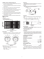
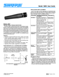
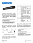
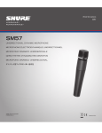
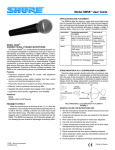
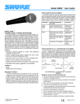
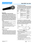
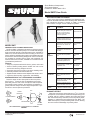
Shure Brothers Incorporated
222 Hartrey Avenue
Evanston IL 60202-3696 U.S.A.
Model SM57 User Guide
APPLICATION AND PLACEMENT
Some of the most common applications and placement techniques for the SM57 are listed in the following table. Remember
that microphone technique is largely a matter of personal
taste—there is no single “correct” microphone position.
APPLICATION
SUGGESTED MICROPHONE
PLACEMENT
TONE QUALITY
Tom–Toms
One SM57 on each tom, or
between each pair of toms, 25
mm (1 in.) to 75 mm (3 in.)
above the heads. Aim each
mic at the top heads.
Medium attack,
balanced sound.
On double head toms, remove
the bottom head and place a
mic inside aimed at the head.
Medium attack,
balanced sound.
25 mm (1 in.) to 75 mm (3 in.)
above the rim of the top head
of the drum. Aim the mic at
the head.
Most “snap”
from drumstick
impact
If desired, place a second mic
just below the rim of the bottom head.
More “snare”
sound.
25 mm (1 in.) from the speaker, on-axis with the speaker
cone.
Most attack,
emphasized
bass
150 mm (6 in.) to 300 mm (12
in.) away from speaker and
on-axis with speaker cone.
Medium attack,
full, balanced
sound
.5 m (18 in.) to 1 m (3 ft) back
from the speaker, on-axis with
the speaker cone.
Softer attack,
thin, reduced
bass sound.
On-axis with the edge of the
speaker cone.
Thinner, reduced bass
sound.
Brass: .3 m (1 ft) to 1 m (3 ft)
away, on-axis with bell of instrument.
Bright, clear
sound.
Woodwinds: 25 mm (1 in.) to
150 mm (6 in.) away, on-axis
with bell of instrument.
Bright, clear
sound.
Bell of the instrument 90° offaxis from the front of the mic.
Softer, mellow
sound.
25 mm (1 in.) to 150 mm (6
in.) from the vocalist’s mouth.
Rich, warm
sound.
Snare Drum
MODEL SM57
UNIDIRECTIONAL DYNAMIC MICROPHONE
The Shure SM57 unidirectional dynamic microphone is exceptional for musical instrument pickup or for vocals. With its bright,
clean sound and carefully contoured presence rise, the SM57 is
ideal for live sound reinforcement and recording. It has an extremely effective cardioid pickup pattern which isolates the main
sound source while minimizing background noise. In the studio,
it is excellent for recording drums, guitar, and woodwinds. For
musical instruments or vocals, the SM57 is a consistent choice
of professional performers.
Features
• Frequency response tailored for drums, guitars, and vocals
• Uniform cardioid pickup pattern isolates the main sound
source while reducing background noise
• Pneumatic shock-mount system cuts down handling noise
• Extremely durable under the heaviest use
• Supplied break-resistant swivel adapter that rotates 180 °
• Legendary Shure quality, ruggedness, and reliability
STAGE MONITOR & P.A. LOUDSPEAKER PLACEMENT
Place the stage monitor directly behind the microphone
(see Figure 1). Locate the P.A. loudspeakers so that they
point away from the rear of the microphone. With the speakers located in these positions, the possibility of feedback is
greatly reduced. Always check the stage setup before a performance to ensure optimum placement.
90°
0°
180°
MICROPHONE
90°
Brass &
Woodwinds
Vocals &
Speech
PROXIMITY EFFECT
STAGE
MONITOR
P.A.
LOUDSPEAKERS
Guitar &
Bass
Amplifiers
SOUND
SOURCE
When the sound source is less than 6 mm (1/4 in.) from the
microphone, the microphone boosts bass frequencies (by 6 to
10 dB at 100 Hz), creating a warmer and richer bass sound
than when farther away. This effect, known as proximity effect,
happens in unidirectional microphones like the SM57. The
SM57 low-frequency roll-off provides greater control, allowing
the user to take full advantage of proximity effect.
RECOMMENDED LOUDSPEAKER PLACEMENT
FIGURE 1
E1998, Shure Brothers Incorporated
27A2903 (RA)
Printed in U.S.A.
GENERAL RULES FOR MICROPHONE USE
Impedance
Rated impedance is 150 (310 actual) for connection to
microphone inputs rated low impedance.
Phasing
Positive pressure on diaphragm produces positive voltage
on pin 2 with respect to pin 3 (see Figure 4)
1. Aim the microphone toward the desired sound source and
away from unwanted sources.
2. Locate the microphone as close as practical to the desired
sound source.
3. Work close to the microphone for extra bass response.
CARTRIDGE
CODED TERMINAL
4. Use only one microphone per sound source.
5. Locate multiple microphones at least three times as far
from other microphones as from the sound source.
GREEN
BLUE
1
2
3
6. Use as few microphones as practical.
YELLOW
RED
BLACK
7. Place microphones away from sound reflecting surfaces.
TRANSFORMER
8. Add a windscreen when using the microphone outdoors, for
closeup speech, or vocals.
INTERNAL CONNECTIONS
FIGURE 4
9. Avoid excessive handling to minimize mechanical noise.
SPECIFICATIONS
Type
Dynamic
Frequency Response
40 to 15,000 Hz (see Figure 2)
Connector
Three-pin professional audio connector (male XLR type)
Case
Dark gray, enamel-painted, die-cast steel with a
polycarbonate grille and a stainless steel screen.
ÁÁÁÁÁÁÁÁÁÁÁÁÁÁÁÁ
ÁÁÁÁÁÁÁÁÁÁÁÁÁÁÁ
Á ÁÁÁÁÁÁÁÁÁÁÁ
ÁÁÁÁÁÁÁÁÁÁÁÁÁÁÁÁ
Á ÁÁÁÁÁÁÁÁÁÁÁ
ÁÁÁÁÁÁÁÁÁÁÁÁÁÁÁÁ
Á ÁÁÁÁÁÁÁÁÁÁÁ
ÁÁÁÁÁÁÁÁÁÁÁÁÁÁÁÁ
Á ÁÁÁÁÁÁÁÁÁÁÁ
ÁÁÁÁÁÁÁÁÁÁÁÁÁÁÁÁ
Á ÁÁÁÁÁÁÁÁÁÁÁ
ÁÁÁÁÁÁÁÁÁÁÁÁÁÁÁÁ
Á ÁÁÁÁÁÁÁÁÁÁÁ
Á Á ÁÁÁÁÁÁÁÁÁÁÁ
157 mm
(6 3/16 in.)
23 mm
(29/32in.)
32 mm
(1 1/4 in.)
DIMENSIONS
FIGURE 5
Swivel Adapter
Positive-action, break-resistant, adjustable through 180°,
with standard 5/8 in.-27 thread
Net Weight (without cable)
284 grams (10 oz)
Certification
Conforms to European Union directives, eligible to bear CE
marking; meets European Union EMC Immunity Requirements (EN 50 082–1, 1992); RF radiated (IEC 801–3); ESD
(IEC 801–2); EFT (IEC 801–4).
TYPICAL FREQUENCY RESPONSE
FIGURE 2
Polar Pattern
Unidirectional (cardioid), rotationally symmetrical about
microphone axis, uniform with frequency (see Figure 3)
FURNISHED ACCESSORIES
Swivel Adapter . . . . . . . . . . . . . . . . . . . . . . . . . . . . . . . A25C
Storage Bag . . . . . . . . . . . . . . . . . . . . . . . . . . . . . . . . 26A13
OPTIONAL ACCESSORIES
Windscreen . . . . . . . . . . . . . . . . . . . . . . . . . . . . . . . . . . A2WS
Desk Stand . . . . . . . . . . . . . . . . . . . . . . . . . . . . . S37A, S39A
Isolation Mount . . . . . . . . . . . . . . . . . . . . . . . . . . . . . . . A55M
Dual Mount . . . . . . . . . . . . . . . . . . . . . . . . . . . . A25M, A26M
Cable (7.6 m [25 ft]) . . . . . . . . . . . . . . . . . . . . . C25E, C25F
REPLACEMENT PARTS
Cartridge . . . . . . . . . . . . . . . . . . . . . . . . . . . . . . . . . . . . . R57
Screen and Grille Assembly . . . . . . . . . . . . . . . . . . RK244G
TYPICAL POLAR PATTERNS
FIGURE 3
Output Level (at 1,000 Hz)
Open Circuit Voltage: –74.5 dB* (0.19 mV)
Power Level: –56.0 dB**
For additional service or parts information, please contact
Shure’s Service department at 1-800-516-2525. Outside the
United States, please contact your authorized Shure Service
Center.
*0 dB = 1 V/bar
**0 dB = 1 mW/10 bar
2