1
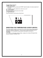
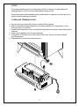
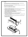
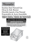
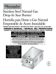
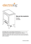
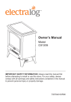
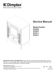
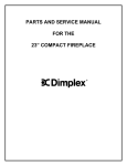
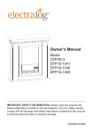
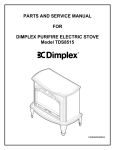
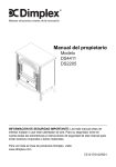
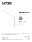
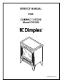
SERVICE MANUAL
FOR
COMPACT STOVE
Model CS1205
7400290000rev01
TABLE OF CONTENTS
OPERATION
PAGE 2
PARTS DRAWING
PAGE 3
PARTS LIST
PAGE 4
WIRING DIAGRAM
PAGE 5
LIGHT BULB REPLACEMENT
PAGE 6
HEATER ON/OFF SWITCH REPLACEMENT
PAGE 7
HEATER ASSEMBLY REPLACEMENT
PAGE 8
TERMINAL BLOCK REPLACEMENT
PAGE 9
FLAME MOTOR/FLAME ROD REPLACEMENT
PAGE 10
POWER CORD REPLACEMENT
PAGE 11
1
Compact Stove Controls
A. Main on/off switch
1. The fireplace has a manual power ON/OFF switch located on the lower right side of
the stove.
2. To operate, press the switch to turn the unit on or off
B. Low Heat Switch
Press this switch to turn the stove to low heat.
C. High Heat Switch
Press this switch to turn the stove to high heat.
RESETTING THE TEMPERATURE CUTOFF SWITCH
Should the heater overheat, an automatic cut out will turn the heater off and it will not
come back on without being reset. It can be reset by switching the MAIN ON/OFF
SWITCH to OFF and waiting 5 minutes before switching the unit back on.
CAUTION
If you need to continuously reset the heater, unplug the unit and call Dimplex North
America Limited at 1-888-346-7539.
2
CS1205
8
9
1
7
2
11
3
12
10
4
3
5
6
CS1205
REPLACEMENT PARTS
COMPACT STOVE, DIMPLEX CHARMGLOW
PART NO.
MOD. LEVEL
REPLACEMENT PART
6902340100
B
REPLACEMENT PART NO.
1. Log Set Assembly
2. Flicker Motor 120V
3. Heater Assembly (comes with cutout)
4. Main On/Off Switch
5. Heater Switch
6. Cord Set 120V
7. Moulded Lampholder
8. Flicker Rod
9. Mirror
10. Foot
11. Terminal Block
12. Capacitor
0477850100RP
2000210200RP
2200491000RP
2800070700RP
2800070200RP
4100090100RP
4200090100RP
5900250100RP
5900530200RP
0477830159RP
4000070100RP
2300030100RP
4
5
CS1205
If unit was operating prior to servicing allow at least 10 minutes for light bulbs and
heating element to cool off to avoid accidental burning of skin.
Disconnect power before attempting any maintenance or cleaning to reduce the risk of
electric shock or damage to persons.
Light bulbs need to be replaced when you notice a dark section of the flame. There are
four bulbs under the log set which generate the flames and embers.
It is a good idea to replace all of the light bulbs at one time if they are close to the end of
their rated life. Group replacement will reduce the number of times you need to open
the unit to replace the light bulbs.
LIGHT BULB REPLACEMENT
1.
2.
3.
4.
5.
6.
7.
Remove the 8 fastening screws on the top panel and remove the top of the stove.
Lift glass out and store in a safe place.
Remove the 5 fastening screws and lift the bulb shield out of the stove.
Examine the bulbs to determine which bulbs require replacement.
Hold the socket while unscrewing the bulb.
Hold the socket while screwing in the new bulb.
Replace the bulb shield and mirror and re-install the top of the stove.
LIGHT BULB REQUIREMENTS
Quantity of 4 clear chandelier or candelabra bulbs with an E-12 (small) socket base,
60 watt rating.
6
CS1205
If unit was operating prior to servicing allow at least 10 minutes for light bulbs and
heating element to cool off to avoid accidental burning of skin.
Disconnect power before attempting any maintenance or cleaning to reduce the risk of
electric shock or damage to persons.
TO REPLACE ON/OFF AND HEATER SWITCHES
1. Turn the stove over and place it top down.
2. Remove the bottom heater assembly cover being careful not to damage any of
the wiring.
3. Remove the 4 heater retaining screws from the bottom of the heater assembly
cover and move the heater to gain access to the switch connections.
4. Locate the switch to be replaced mounted on heater assembly cover and
disconnect the wiring clips and connections noting their original locations.
5. Depress the retainer clips on the rear of the switch and push the switch out of the
rear of the cover.
7
CS1205
If unit was operating prior to servicing allow at least 10 minutes for light bulbs and
heating element to cool off to avoid accidental burning of skin.
Disconnect power before attempting any maintenance or cleaning to reduce the risk of
electric shock or damage to persons.
TO REPLACE HEATER ASSEMBLY
1. Turn the stove over and place it top down.
2. Remove the bottom heater assembly cover being careful not to damage any of the
wiring.
3. Remove the 4 heater retaining screws from the bottom of the heater assembly cover
and move the heater to gain access to the heater connections being careful not to
damage any of the wiring.
4. Disconnect the 2 heater switch leads from the heater.
5. Remove the wire nut and disconnect the thermal cut-out wire.
6. Remove the 2 mounting brackets from the bottom of the old heater and install them
on the new heater.
7. Reassemble in the reverse order as above.
8
CS1205
If unit was operating prior to servicing allow at least 10 minutes for light bulbs and
heating element to cool off to avoid accidental burning of skin.
Disconnect power before attempting any maintenance or cleaning to reduce the risk of
electric shock or damage to persons.
TO REPLACE TERMINAL BLOCK
1. Lay the stove on its back with the front window facing upward.
2. Remove the bottom heater assembly cover being careful not to damage any of the
wiring and lay it on the floor.
3. Loosen the connections on the terminal block and remove the wires noting their original
locations.
4. Remove the capacitor from the terminal block
5. Using pliers to hold the nuts on the inside of the stove, remove the terminal block
mounting screws.
6. Reassemble in the reverse order as above.
9
CS1205
If unit was operating prior to servicing allow at least 10 minutes for light bulbs and
heating element to cool off to avoid accidental burning of skin.
Disconnect power before attempting any maintenance or cleaning to reduce the risk of
electric shock or damage to persons.
TO REPLACE FLAME MOTOR/FLAME ROD
1.
2.
3.
4.
Remove the 8 fastening screws on the top panel and remove the top of the stove.
Lift glass out and store in a safe place.
Remove the log set by sliding to the rear of the stove and lifting out.
Remove the reflector rod from the flame motor by pulling the end of the rod to the
left and separating it from the rubber sleeve.
5. Remove the rubber sleeve from the motor shaft.
6. Remove the 2 motor mounting screws and remove the flame motor.
7. Discard the old flame motor.
8. Lay the stove on its back with the front window facing upward.
9. Remove the bottom heater assembly cover being careful not to damage any of the
wiring and lay it on the floor.
10. Loosen the flame motor connections on the terminal block and remove the wires
noting their original locations.
11. Reassemble in the reverse order.
10
CS1205
If unit was operating prior to servicing allow at least 10 minutes for light bulbs and
heating element to cool off to avoid accidental burning of skin.
Disconnect power before attempting any maintenance or cleaning to reduce the risk of
electric shock or damage to persons.
TO REPLACE THE POWER CORD
1. Turn the stove over and place it top down.
2. Remove the bottom heater assembly cover being careful not to damage any of the
wiring.
3. Remove the 4 heater retaining screws from the bottom of the heater assembly cover
and move the heater to gain access to the switch connections.
4. Located and disconnect the power cord wiring connections from the heater and Main
on/off switch noting their original locations.
5. With needle nose pliers grasp the power cord strain relief grommet from inside the
rear panel and push while twisting to remove.
6. Pull the power cord out through the hole in the rear cover.
7. Install the new cord set through the hole in the rear cover by placing the strain relief
over the cord, hold the strain relief with pliers and slide into mounting hole.
8. Connect all of the wiring connections in their original locations.
9. Reassemble in the reverse order as above.
11