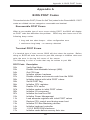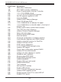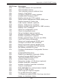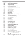
1
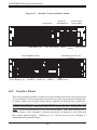
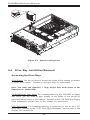
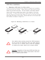
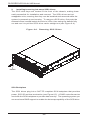
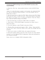
SUPER
®
SUPERSERVER 6034H-X8R
USER’S MANUAL
1.0
The information in this User’s Manual has been carefully reviewed and is believed to be
accurate. The vendor assumes no responsibility for any inaccuracies that may be
contained in this document, makes no commitment to update or to keep current the
information in this manual, or to notify any person or organization of the updates. Please
Note: For the most up-to-date version of this manual, please see our
web site at www.supermicro.com.
SUPERMICRO COMPUTER reserves the right to make changes to the product described in
this manual at any time and without notice. This product, including software, if any, and
documentation may not, in whole or in part, be copied, photocopied, reproduced, translated
or reduced to any medium or machine without prior written consent.
IN NO EVENT WILL SUPERMICRO COMPUTER BE LIABLE FOR DIRECT, INDIRECT,
SPECIAL, INCIDENTAL, SPECULATIVE OR CONSEQUENTIAL DAMAGES ARISING FROM
THE USE OR INABILITY TO USE THIS PRODUCT OR DOCUMENTATION, EVEN IF
ADVISED OF THE POSSIBILITY OF SUCH DAMAGES. IN PARTICULAR, THE VENDOR
SHALL NOT HAVE LIABILITY FOR ANY HARDWARE, SOFTWARE, OR DATA STORED
OR USED WITH THE PRODUCT, INCLUDING THE COSTS OF REPAIRING, REPLACING,
INTEGRATING, INSTALLING OR RECOVERING SUCH HARDWARE, SOFTWARE, OR
DATA.
Any disputes arising between manufacturer and customer shall be governed by the laws of
Santa Clara County in the State of California, USA. The State of California, County of
Santa Clara shall be the exclusive venue for the resolution of any such disputes.
Supermicro's total liability for all claims will not exceed the price paid for the hardware
product.
Unless you request and receive written permission from SUPER MICRO COMPUTER,
you may not copy any part of this document.
Information in this document is subject to change without notice. Other products and
companies referred to herein are trademarks or registered trademarks of their respective
companies or mark holders.
Copyright © 2004 by SUPER MICRO COMPUTER INC.
All rights reserved.
Printed in the United States of America
Preface
Preface
About This Manual
This manual is written for professional system integrators and PC technicians. It provides information for the installation and use of the SuperServer
6034H-X8R. Installation and maintainance should be performed by experienced technicians only.
The SuperServer 6034H-X8R is a high-end, dual processor server based on
the SC833S-R760 3U rackmount server chassis and the Super X6DH8-XG2,
a dual processor serverboard that supports single or dual Intel ® Xeon TM
processors at a Front Side (System) Bus speed of 800 MHz and up to 16
GB of registered ECC DDR2-400 SDRAM.
Manual Organization
Chapter 1: Introduction
The first chapter provides a checklist of the main components included with
the server system and describes the main features of the X6DH8-XG2
serverboard and the SC833S-R760 chassis, which comprise the
SuperServer 6034H-X8R.
Chapter 2: Server Installation
This chapter describes the steps necessary to install the SuperServer
6034H-X8R into a rack and check out the server configuration prior to powering up the system. If your server was ordered without processor and
memory components, this chapter will refer you to the appropriate sections
of the manual for their installation.
Chapter 3: System Interface
Refer here for details on the system interface, which includes the functions
and information provided by the control panel on the chassis as well as
other LEDs located throughout the system.
iii
SUPERSERVER 6034H-X8R Manual
Chapter 4: System Safety
You should thoroughly familiarize yourself with this chapter for a general
overview of safety precautions that should be followed when installing and
servicing the SuperServer 6034H-X8R.
Chapter 5: Advanced Serverboard Setup
Chapter 5 provides detailed information on the X6DH8-XG2 serverboard,
including the locations and functions of connections, headers and jumpers.
Refer to this chapter when adding or removing processors or main memory
and when reconfiguring the serverboard.
Chapter 6: Advanced Chassis Setup
Refer to Chapter 6 for detailed information on the SC833S-R7600 server
chassis. You should follow the procedures given in this chapter when
installing, removing or reconfiguring SCSI or peripheral drives and when
replacing system power supply units and cooling fans.
Chapter 7: BIOS
The BIOS chapter includes an introduction to BIOS and provides detailed
information on running the CMOS Setup Utility.
Appendix A: BIOS POST Codes
Appendix B: Software Installation
Appendix C: System Specifications
iv
Preface
Notes
v
SUPERSERVER 6034H-X8R Manual
Table of Contents
Preface
About This Manual ...................................................................................................... iii
Manual Organization ................................................................................................... iii
Chapter 1: Introduction
1-1
Overview ......................................................................................................... 1-1
1-2
Serverboard Features ................................................................................... 1-2
1-3
Server Chassis Features .............................................................................. 1-3
1-4
Contacting Supermicro .................................................................................. 1-6
Chapter 2: Quick Setup
2-1
Overview ......................................................................................................... 2-1
2-2
Unpacking the System ................................................................................... 2-1
2-3
Preparing for Setup ....................................................................................... 2-1
2-4
Installing the System into a Rack ................................................................ 2-4
2-5
Checking the Serverboard Setup ................................................................ 2-8
2-6
Checking the Drive Bay Setup ................................................................... 2-10
Chapter 3: System Interface
3-1
Overview ......................................................................................................... 3-1
3-2
Control Panel Buttons .................................................................................... 3-1
Mute ........................................................................................................... 3-1
Reset .......................................................................................................... 3-1
Power ........................................................................................................ 3-2
3-3
Control Panel LEDs ........................................................................................ 3-2
Overheat/Fan Fail .................................................................................... 3-2
NIC2 ............................................................................................................ 3-2
NIC1 ............................................................................................................ 3-3
HDD ............................................................................................................ 3-3
Power ........................................................................................................ 3-3
Power Fail ................................................................................................. 3-3
3-4
SCSI Drive Carrier LEDs ............................................................................... 3-4
Chapter 4: System Safety
4-1
Electrical Safety Precautions ........................................................................ 4-1
4-2
General Safety Precautions .......................................................................... 4-2
4-3
ESD Safety Precautions ................................................................................. 4-3
4-4
Operating Precautions .................................................................................... 4-4
vi
Table of Contents
Chapter 5: Advanced Serverboard Setup
5-1
Handling the Serverboard .............................................................................. 5-1
5-2
PGA Processor and Heatsink Installation ................................................... 5-2
5-3
Connecting Cables .......................................................................................... 5-4
Connecting Data Cables .......................................................................... 5-4
Connecting Power Cables ....................................................................... 5-4
Connecting the Control Panel ................................................................. 5-5
5-4
I/O Ports ............................................................................................................ 5-6
5-5
Installing Memory ............................................................................................. 5-6
5-6
Adding PCI Cards ............................................................................................ 5-8
5-7
Serverboard Details ........................................................................................ 5-9
X6DH8-XG2 Layout ................................................................................ 5-10
X6DH8-XG2 Quick Reference .............................................................. 5-10
5-8
Connector Definitions .................................................................................. 5-11
ATX Power Connector .......................................................................... 5-11
Processor Power Connector ............................................................... 5-11
NMI Button ............................................................................................... 5-11
Power LED .............................................................................................. 5-11
HDD LED .................................................................................................. 5-12
NIC1/NIC2 LED ......................................................................................... 5-12
Overheat/Fan Fail LED .......................................................................... 5-12
Power Fail LED ...................................................................................... 5-12
Reset Button ........................................................................................... 5-13
Power Button .......................................................................................... 5-13
Chassis Intrusion .................................................................................... 5-13
Universal Serial Bus .............................................................................. 5-13
Fan Headers ........................................................................................... 5-14
Serial Ports ............................................................................................. 5-14
JLAN 1/2 (Ethernet Ports) .................................................................... 5-14
ATX PS/2 Keyboard and Mouse Ports ............................................... 5-14
Power LED/Speaker/NMI ....................................................................... 5-15
Wake-On-Ring ......................................................................................... 5-15
Wake-On-LAN ........................................................................................ 5-15
SMB ......................................................................................................... 5-15
Power Fault ............................................................................................. 5-16
Keylock .................................................................................................... 5-16
SMB Power Connector ......................................................................... 5-16
Overheat LED ......................................................................................... 5-16
vii
SUPERSERVER 6034H-X8R Manual
5-9
Jumper Settings ............................................................................................ 5-17
Explanation of Jumpers ........................................................................ 5-17
CMOS Clear ............................................................................................. 5-17
LAN Enable/Disable ............................................................................... 5-18
SCSI Controller Enable/Disable ............................................................ 5-18
SCSI Termination Enable/Disable ......................................................... 5-18
Watch Dog Enable/Disable ................................................................... 5-19
VGA Enable/Disable .............................................................................. 5-19
Power Force On Enable/Disable ......................................................... 5-19
Third Power Supply Alarm Enable/Disable ........................................ 5-20
Alarm Reset ............................................................................................ 5-20
5-10 Onboard Indicators ...................................................................................... 5-21
LAN1/LAN2 LEDs ................................................................................... 5-21
5-11 Floppy/Hard Disk Drive and SCSI Connections ....................................... 5-21
Floppy Connector ................................................................................... 5-22
IDE Connectors ...................................................................................... 5-22
Ultra320 SCSI Connectors .................................................................... 5-23
Chapter 6: Advanced Chassis Setup
6-1
Static-Sensitive Devices ................................................................................. 6-1
6-2
Control Panel .................................................................................................... 6-2
6-3
System Fans .................................................................................................... 6-3
Fan Failure ................................................................................................. 6-3
Replacing System Fans ........................................................................... 6-3
6-4
Drive Bay Installation/Removal ...................................................................... 6-4
SCSI Drive Installation ............................................................................. 6-5
Installing Components in the 5.25" Drive Bays .................................. 6-8
CD-ROM and Floppy Drive Installation ................................................. 6-9
6-5
Power Supply ................................................................................................ 6-11
Power Supply Failure ............................................................................ 6-11
Removing/Replacing the Power Supply .............................................. 6-11
Chapter 7: BIOS
7-1
Introduction ....................................................................................................... 7-1
7-2
Running Setup ................................................................................................... 7-2
7-3
Main BIOS Setup .............................................................................................. 7-2
7-4
Advanced Setup ................................................................................................. 7-7
7-5
Security ............................................................................................................ 7-19
7-6
Boot ................................................................................................................... 7-21
7-7
Exit ................................................................................................................... 7-22
viii
Table of Contents
Appendices:
Appendix A: BIOS POST Codes ............................................................................ A - 1
Appendix B: Software Installation ......................................................................... B-1
Appendix C: System Specifications ...................................................................... C-1
ix
SUPERSERVER 6034H-X8R Manual
Notes
x
Chapter 1: Introduction
Chapter 1
Introduction
1-1
Overview
The Supermicro SuperServer 6034H-X8R is a high-end dual processor
server that is comprised of two main subsystems: the SC833S-R760 3U
server chassis and the X6DH8-XG2 dual Intel Xeon processor serverboard.
Please refer to our web site for information on operating systems that have
been certified for use with the 6034H-X8R (www.supermicro.com).
In addition to the serverboard and chassis, various hardware components
have been included with the SuperServer 6034H-X8R, as listed below:
z
One (1) 3.5" floppy drive [FPD-TEAC (B)]
z
Two (2) 8-cm hot-swap exhaust fans (FAN-0062)
z
Four (4) 9-cm hot-swap chassis fans (FAN-0064)
z
One (1) 3U chassis air shroud (CSE-PT44)
z
One (1) 3U chassis air shroud side piece (CSE-PT45)
z
Two (2) 5.25" dummy drive trays [CSE-PT36 (B)]
z
One (1) front control panel cable (CBL-0049)
z
One (1) round floppy cable (CBL-0040)
z
One (1) round CD-ROM cable (CBL-0039)
z
SCSI Accessories
One (1) SCSI backplane [CSE-SCA-833S]
One (1) SCSI cable (CBL-0033-U320)
Eight (8) SCA 1-inch high SCSI drive carriers [CSE-PT39(B)]
z
One (1) rackmount kit [CSE-PT50 (B)]
z
Optional: Two (2) Xeon passive heatsinks (SNK-P0010)
1-1
SUPERSERVER 6034H-X8R Manual
1-2
Serverboard Features
At the heart of the SuperServer 6034H-X8R lies the X6DH8-XG2, a dual
processor serverboard based on the Intel E7520 chipset and designed to
provide maximum performance. Below are the main features of the X6DH8XG2. (See Figure 1-1 for a block diagram of the E7520 chipset).
Processors
The X6DH8-XG2 supports single or dual 604-pin Intel Xeon TM EM64T processors at a FSB speed of 800 MHz. Please refer to the serverboard description pages on our web site for a complete listing of supported processors
(www.supermicro.com).
Memory
The X6DH8-XG2 has eight 240-pin DIMM slots that can support up to 16 GB
of registered ECC DDR2-400 (PC3200) SDRAM. The memory is an interleaved configuration, which requires modules of the same size and speed
to be installed in pairs.
Onboard SCSI
Onboard SCSI is provided with an Adaptec AIC-7902 SCSI chip, which supports dual channel, Ultra320 SCSI at a throughput of 320 MB/sec for each
channel. The X6DH8-XG2 provides two LVD Ultra320 SCSI ports.
PCI Expansion Slots
The X6DH8-XG2 has two PXH hubs that support one PCI-Express slot and
five PCI-X expansion slots. These expansion slots include one x8 PCIExpress slot, three 64-bit 133 MHz PCI-X slots and two 64-bit 100 MHz PCIX slots.
Onboard Controllers/Ports
One floppy drive controller and two onboard ATA/100 controllers are provided to support up to four IDE hard drives or ATAPI devices. The colorcoded I/O ports include one COM port (an additional COM header is located
on the serverboard), a VGA (monitor) port, two USB 2.0 ports, PS/2 mouse
and keyboard ports and two gigabit Ethernet ports.
1-2
Chapter 1: Introduction
ATI Graphics Controller
The X6DH8-XG2 features an integrated ATI video controller based on the
Rage XL graphics chip. Rage XL fully supports sideband addressing and
AGP texturing. This onboard graphics package can provide a bandwidth of
up to 512 MB/sec over a 32-bit graphics memory bus.
Other Features
Other onboard features that promote system health include onboard voltage
monitors, a chassis intrusion header, auto-switching voltage regulators, chassis
and CPU overheat sensors, virus protection and BIOS rescue.
1-3
Server Chassis Features
The SuperServer 6034H-X8R is a high-end, scaleable server platform designed with today's most state-of-the-art features. The following is a general outline of the main features of the SC833S-R760 server chassis.
System Power
The 6034H-X8R features a triple redundant 760W power supply that consists of three separate power supply modules. These modules all share the
load and run continuously. If any of the three fail, the remaining two pick up
the load and keep the system running without interruption. A failed power
supply module will illuminate the power fail LED. The power supply modules
are all hot-swappable, so you don't have to power down the system to
replace a module.
SCSI Subsystem
The SCSI subsystem supports up to eight 80-pin SCA Ultra320 SCSI hard
drives. Any standard 1" drives are supported. SCA = Single Connection
Attachment.) The SCSI drives are connected to a dual-channel SCA
backplane with SAF-TE. The SCSI drives are also hot-swap units. A RAID
controller card can be used with the SCA backplanes to provide data security.
Note: The operating system you use must have RAID support to enable the
hot-swap capability of the SCSI drives.
1-3
SUPERSERVER 6034H-X8R Manual
Front Control Panel
The SuperServer 6034H-X8R's control panel provides you with system monitoring and control. LEDs indicate system power, HDD activity, network
activity, overheat condition and power supply failure. A main power button
and a system reset button are also included.
I/O Backplane
The SC833S-R760 is an ATX form factor chassis that is designed to be
used in a 3U rackmount configuration. The I/O backplane provides six motherboard expansion slots, one COM port, a VGA port, two USB 2.0 ports, PS/
2 mouse and keyboard ports and two gigabit Ethernet ports.
Cooling System
The SC833S-R760 chassis has an innovative cooling design that includes
four 9-cm hot-plug system cooling fans located in the middle section of the
chassis and two 8-cm hot-plug rear exhaust fans. Each power supply
module also includes a cooling fan. All chassis and power supply fans
operate continuously.
A setting in BIOS (see p. 7-18) is used to determine the fan speed. [The
recommended setting for the 6034H-X8R is "3-pin (Server)".]
1-4
Chapter 1: Introduction
Figure 1-1. Intel E7520 Chipset:
System Block Diagram
Note: This is a general block diagram. Please see Chapter 5 for details.
NOCONA CPU 1
1 PCI-X
SLOT
J13
NOCONA CPU 2
SCSI
7902
1 PCI-X
SLOT
ZCR
J12
1 PCI-X
SLOT
J14
Gbit LAN
ANVIK
PCI-X(100MHz)
A
X4 PCI E. A (X8)
PXH
B
PCI-X(133MHz)
1 PCI-EXP X4
SLOT
1 PCI-E
J17
PCI-E B (X8 )
SLOT
J15
PCI-E C (X8 )
1 PCI-E
SLOT
UDMA/100
IDE
J16
PRI/SEC
SATA
0, 1
USB PORT
DDRII-400
MCH
DDRII-400
4 DDR II 4 DIMMs
4 DDR II 4 DIMMs
HUB
SATA
PCI (32-BIT)
ICH5
USB
VGA
LPC BUS
0,1,2,3,4,5
LPCS I/O
KB.
MS.
FDD.
1-5
SER.1
SER.2
BMC CON.
H/W
MONITOR
FWH
LPCS I/O
PARALL.
PORT
SUPERSERVER 6034H-X8R Manual
1-4
Contacting Supermicro
Headquarters
Address:
Tel:
Fax:
Email:
Web Site:
SuperMicro Computer, Inc.
980 Rock Ave.
San Jose, CA 95131 U.S.A.
+1 (408) 503-8000
+1 (408) 503-8008
[email protected] (General Information)
[email protected] (Technical Support)
www.supermicro.com
Europe
Address:
Tel:
Fax:
Email:
SuperMicro Computer B.V.
Het Sterrenbeeld 28, 5215 ML
's-Hertogenbosch, The Netherlands
+31 (0) 73-6400390
+31 (0) 73-6416525
[email protected] (General Information)
[email protected] (Technical Support)
[email protected] (Customer Support)
Asia-Pacific
Address:
SuperMicro, Taiwan
D5, 4F, No. 16 Chien-Ba Road
Chung-Ho 235, Taipei Hsien, Taiwan, R.O.C.
Tel:
+886-(2) 8226-3990
Fax:
+886-(2) 8226-3991
Web Site:
www.supermicro.com.tw
Technical Support:
Email:
[email protected]
Tel:
886-2-8228-1366, ext.132 or 139
1-6
Chapter 2: Server Installation
Chapter 2
Server Installation
2-1 Overview
This chapter provides a quick setup checklist to get your SuperServer
6034H-X8R up and running. Following these steps in the order given should
enable you to have the system operational within a minimum amount of time.
This quick setup assumes that your system has come to you with the processors and memory preinstalled. If your system is not already fully integrated with a serverboard, processors, system memory etc., please turn to
the chapter or section noted in each step for details on installing specific
components.
2-2
Unpacking the System
You should inspect the box the SuperServer 6034H-X8R was shipped in
and note if it was damaged in any way. If the server itself shows damage
you should file a damage claim with the carrier who delivered it.
Decide on a suitable location for the rack unit that will hold the SuperServer
6034H-X8R. It should be situated in a clean, dust-free area that is well
ventilated. Avoid areas where heat, electrical noise and electromagnetic
fields are generated. You will also need it placed near a grounded power
outlet. Read the Rack and Server Precautions in the next section.
2-3
Preparing for Setup
The box the SuperServer 6034H-X8R was shipped in should include two
sets of rail assemblies, two rail mounting brackets and the mounting screws
you will need to install the system into the rack. Follow the steps in the
order given to complete the installation process in a minimum amount of time.
Please read this section in its entirety before you begin the installation
procedure outlined in the sections that follow.
2-1
SUPERSERVER 6034H-X8R Manual
Choosing a Setup Location
- Leave enough clearance in front of the rack to enable you to open
the front door completely (~25 inches).
- Leave approximately 30 inches of clearance in the back of the rack
to allow for sufficient airflow and ease in servicing.
!
Warnings and Precautions!
!
Rack Precautions
- Ensure that the leveling jacks on the bottom of the rack are fully
extended to the floor with the full weight of the rack resting on them.
- In single rack installation, stabilizers should be attached to the rack.
- In multiple rack installations, the racks should be coupled together.
- Always make sure the rack is stable before extending a component
from the rack.
- You should extend only one component at a time - extending two or
more simultaneously may cause the rack to become unstable.
Server Precautions
- Review the electrical and general safety precautions in Chapter 4.
- Determine the placement of each component in the rack before you
install the rails.
- Install the heaviest server components on the bottom of the rack
first, and then work up.
- Use a regulating uninterruptible power supply (UPS) to protect the
server from power surges, voltage spikes and to keep your
system operating in case of a power failure.
- Allow the hot plug SCSI drives and power supply units to cool before
touching them.
- Always keep the rack's front door and all panels and components on
the servers closed when not servicing to maintain proper cooling.
2-2
Chapter 2: Server Installation
Rack Mounting Considerations
Ambient Operating Temperature
If installed in a closed or multi-unit rack assembly, the ambient operating
temperature of the rack environment may be greater than the ambient
temperature of the room. Therefore, consideration should be given to
installing the equipment in an environment compatible with the manufacturer’s
maximum rated ambient temperature (Tmra).
Reduced Airflow
Equipment should be mounted into a rack so that the amount of airflow
required for safe operation is not compromised.
Mechanical Loading
Equipment should be mounted into a rack so that a hazardous condition does
not arise due to uneven mechanical loading.
Circuit Overloading
Consideration should be given to the connection of the equipment to the power
supply circuitry and the effect that any possible overloading of circuits might have
on overcurrent protection and power supply wiring. Appropriate consideration of
equipment nameplate ratings should be used when addressing this concern.
Reliable Ground
A reliable ground must be maintained at all times. To ensure this, the rack itself
should be grounded. Particular attention should be given to power supply connections other than the direct connections to the branch circuit (i.e. the use of
power strips, etc.).
2-3
SUPERSERVER 6034H-X8R Manual
2-4
Installing the System into a Rack
This section provides information on installing the SuperServer 6034H-X8R
into a rack unit. If the 6034H-X8R has already been mounted into a rack,
you can skip ahead to Sections 2-5 and 2-6. There are a variety of rack
units on the market, which may mean the assembly procedure will differ
slightly. The following is a guideline for installing the 6034H-X8R into a rack
with the rack rails provided. You should also refer to the installation in
structions that came with the rack unit you are using.
Identifying the Sections of the Rack Rails
You should have received two rack rail assemblies with the SuperServer
6034H-X8R.
Each of these assemblies consist of two sections: an inner
fixed chassis rail that secures to the 6034H-X8R (A) and an outer fixed
rack rail that secures directly to the rack itself (B).
All screws and hard
ware mentioned in the installation steps should be included in the hard
ware kit.
To remove the fixed chassis rail (A), pull it out as far as possible - you
should hear a "click" sound as a locking tab emerges from inside the rail
assembly and locks the inner rail. Then depress the locking tab to pull the
inner rail completely out. Do this for both the left and right side rack rail
assemblies.
Figure 2-1.
Identifying the Sections of the Rack Rails
B
Locking Tab
A
2-4
Chapter 2: Server Installation
Installing the Chassis Rails
Position one of the fixed chassis rail sections you just removed along the side
of the 6034H-X8R. Note that these two rails are left/right specific. Locate
the five rail buttons on each side of the chassis and the five corresponding
holes on each of the inner rails. Note that the holes are elongated with one
end of the hole larger than the other. Align the larger end of each hole with
its corresponding button. Once all are aligned, push the holes toward their
corresponding buttons and the rail should secure itself to the chassis see
Figure 2-2). Once a rail is placed on the chassis, pull it forward until the rail
buttons lock in the small ends of the corresponding holes. Secure the rail to
the chassis with a M4 x 4mm roundhead screw. Repeat the above steps to
install other rail on the chassis.
Locking Tabs: As mentioned, both chassis rails have a locking tab, which
serves two functions. The first is to lock the server into place when installed and
pushed fully into the rack, which is its normal position. Secondly, these tabs
also lock the server in place when fully extended from the rack. This prevents
the server from coming completely out of the rack when you pull it out for
servicing.
Figure 2-2. Installing Chassis Rails
2-5
SUPERSERVER 6034H-X8R Manual
Installing the Server into the Rack
Locate a pair of front (short) and rear (long) brackets that were included with
your rack mounting hardware. Note that the brackets are marked with up/front
arrows (front) and up/rear arrows (rear). Secure the short front bracket (A in
Figure 2-3) to the outer rail with two M4 x 4 mm roundhead screws. Locate
the two buttons on the outer rail (B in Figure 2-3) and attach the rear (long)
bracket to it by sliding the opening of the rear rail through the button. Measure
the depth of your rack and adjust the length of the rails accordingly. Repeat
the same steps to install the other outer rail on the chassis. Secure both
outer rail assemblies to the rack using M5 x 12 mm flathead screws and M5
washers.
You are now ready to install the server into the rack. Slide the chassis into
the rack as shown in Figure 2-4. The chassis may not slide into the rack
smoothly or easily when installed the first time. Some adjustment to the slide
assemblies might be needed for easy installation.)
When the server has been pushed completely into the rack, you should hear
the locking tabs "click". You will need to release the safety taps on both sides
of the chassis in order to completely remove the chassis out of the rack.
Figure 2-3. Assembling the Rack Rails
B
A
Screws
2-6
Chapter 2: Server Installation
Figure 2-4. Installing the Server into a Rack
Installing the Server into a Telco Rack
If you are installing the SuperServer 6034H-X8R into a Telco type rack,
follow the directions given on the previous pages for rack installation. The
only difference in the installation procedure will be the positioning of the
rack brackets to the rack. They should be spaced apart just enough to
accommodate the width of the telco rack.
2-7
SUPERSERVER 6034H-X8R Manual
2-5
Checking the Serverboard Setup
After you install the 6034H-X8R in the rack, you will need to open the unit to
make sure the serverboard is properly installed and all the connections
have been made.
1. Accessing the inside of the 6034H-X8R (see Figure 2-5):
First, release the retention screws that secure the unit to the rack.
Grasp the two handles on either side and pull the unit straight out until it
locks (you will hear a "click"). Next, depress the two buttons on the top
of the chassis to release the top cover. You can then lift the top cover
from the chassis to gain full access to the inside of the server.
2. Check the CPUs (processors):
You may have one or two processors already installed into the serverboard.
Each processor needs its own heatsink. See Chapter 5 for instructions on
processor and heatsink installation.
3. Check the system memory:
Your 6034H-X8R server system may have come with system memory
already installed. Make sure all DIMMs are fully seated in their slots. For
details on adding system memory, refer to Chapter 5.
4. Installing add-on cards:
If desired, you can install add-on cards to the system. See Chapter 5 for
details on installing PCI add-on cards.
5. Check all cable connections and airflow:
Make sure all power and data cables are properly connected and not
blocking the chassis airflow. Also make sure that no cables are positioned in front of the fans. See Chapter 5 for details on cable connections.
2-8
Chapter 2: Server Installation
Figure 2-5.
Accessing the Inside of the 6034H-X8R
2-9
SUPERSERVER 6034H-X8R Manual
2-6
Checking the Drive Bay Setup
Next, you should check to make sure the peripheral drives and the SCSI drives
and SCA backplane have been properly installed and all connections have been
made.
1. Accessing the drive bays:
All drives are accessable from the front of the server. For servicing the
CD-ROM and floppy drives, you will need to remove the top chassis
cover. The SCSI disk drives can be installed and removed from the front
of the chassis without removing the top chassis cover.
2. CD-ROM and floppy disk drives:
A slim CD-ROM and a floppy drive should be preinstalled in your server. Refer
to Chapter 6 if you need to reinstall a CD-ROM and/or floppy disk drive to the
system.
3. Check the SCSI disk drives:
Depending upon your system's configuration, your system may have one or
more drives already installed. If you need to install SCSI drives, please refer
to Chapter 6.
4. Check the airflow:
Airflow is provided by four 9-cm center chassis cooling fans and two 8-cm rear
chassis exhaust fans. An air shroud is also included in the system to maximize airflow. The system component layout was carefully designed to direct
sufficient cooling airflow to the components that generate the most heat. Note
that all power and data cables have been routed in such a way that they do
not block the airflow generated by the fans.
5. Supplying power to the system:
The last thing you must do is to provide input power to the system. Plug
the power cords from the power supply units into a high-quality power strip
that offers protection from electrical noise and power surges. It is recommended that you use an uninterruptible power supply (UPS).
2-10
Chapter 3: System Interface
Chapter 3
System Interface
3-1
Overview
There are several LEDs on the control panel as well as others on the SCSI drive
carriers and the serverboard to keep you constantly informed of the overall status
of the system as well as the activity and health of specific components. There
are also two buttons on the chassis control panel.
3-2
Control Panel Buttons
There are three push-button buttons located on the front of the chassis. These
are (in order from left to right) a mute, a reset and a power on/off button.
MUTE
z
MUTE: Depress the mute button to silence the buzzer alarm, which is
activated by a signal received from the SCSI drive backplane. After silencing the
alarm, you should then press the button again to reactivate the alarm function.
z
RESET: Use the reset button to reboot the system.
3-1
SUPERSERVER 6034H-X8R User's Manual
z
POWER: This is the main power button, which is used to apply or turn
off the main system power. Turning off system power with this button
removes the main power but keeps standby power supplied to the system.
3-3
Control Panel LEDs
The control panel located on the front of the SC833S-R760 chassis has six
LEDs. These LEDs provide you with critical information related to different
parts of the system. This section explains what each LED indicates when
illuminated and any corrective action you may need to take.
z
Overheat/Fan Fail: IWhen this LED flashes, it indicates a fan failure.
When on continuously it indicates an overheat condition, which may be
caused by cables obstructing the airflow in the system or the ambient room
temperature being too warm. Check the routing of the cables and make
sure all fans are present and operating normally. You should also check to
make sure that the chassis covers are installed. Finally, verify that the
heatsinks are installed properly (see Chapter 5). This LED will remain flashing or on as long as the indicated condition exists.
z
NIC2:
Indicates network activity on LAN2 when flashing.
3-2
Chapter 3: System Interface
z
NIC1:
Indicates network activity on LAN1 when flashing.
z
HDD: Indicates IDE channel activity. On the SuperServer 6034H-X8R,
this LED indicates SCSI and CD-ROM drive activity when flashing.
z
Power: Indicates power is being supplied to the system's power
supply units. This LED should normally be illuminated when the system is
operating.
z
Power Fail: Indicates a power supply module has failed. This should
be accompanied by an audible alarm. A backup power supply module will
take the load and keep the system running but the failed module will need to
be replaced. Refer to Chapter 6 for details on replacing the power supply.
This LED should be off when the system is operating normally.
3-3
SUPERSERVER 6034H-X8R User's Manual
3-4
SCSI Drive Carrier LEDs
Each SCSI drive carrier has two LEDs.
z
Green: When illuminated, the green LED on the front of the SCSI drive
carrier indicates drive activity. A connection to the SCSI SCA backplane enables
this LED to blink on and off when that particular drive is being accessed.
z
Red: A SAF-TE compliant backplane is needed to activate the red LED,
which indicates a drive failure. (A SAF-TE compliant SCSI backplane is standard
on the 6034H-X8R.) If one of the SCSI drives fail, you should be notified by
your system management software. Please refer to Chapter 6 for instructions on replacing failed SCSI drives.
3-4
Chapter 4: System Safety
Chapter 4
System Safety
4-1
Electrical Safety Precautions
!
Basic electrical safety precautions should be followed to protect yourself from
harm and the SuperServer 6034H-X8R from damage:
z Be aware of the locations of the power on/off switch on the chassis as well
as the room's emergency power-off switch, disconnection switch or
electrical outlet. If an electrical accident occurs, you can then quickly
remove power from the system.
z Do not work alone when working with high voltage components.
z Power should always be disconnected from the system when removing or
installing main system components, such as the serverboard, memory
modules and the CD-ROM and floppy drives. When disconnecting power,
you should first power down the system with the operating system and
then unplug the power cords of all the power supply units in the system.
z When working around exposed electrical circuits, another person who is
familiar with the power-off controls should be nearby to switch off the power
if necessary.
z Use only one hand when working with powered-on electrical equipment. This
is to avoid making a complete circuit, which will cause electrical shock.
Use extreme caution when using metal tools, which can easily damage
any electrical components or circuit boards they come into contact with.
z Do not use mats designed to decrease electrostatic discharge as protection
from electrical shock. Instead, use rubber mats that have been specifically
designed as electrical insulators.
z The power supply power cord must include a grounding plug and must be
plugged into grounded electrical outlets.
4-1
SUPERSERVER 6034H-X8R Manual
z Serverboard Battery: CAUTION - There is a danger of explosion if the onboard
battery is installed upside down, which will reverse its polarities. This
battery must be replaced only with the same or an equivalent type
recommended by the manufacturer. Dispose of used batteries according
to the manufacturer's instructions.
z CD-ROM Laser: CAUTION - this server may have come equipped with a CDROM drive. To prevent direct exposure to the laser beam and hazardous
radiation exposure, do not open the enclosure or use the unit in any
unconventional way.
4-2
General Safety Precautions
!
Follow these rules to ensure general safety:
z Keep the area around the SuperServer 6034H-X8R clean and free of
clutter.
z The SuperServer 6034H-X8R weighs approximately 75 lbs (34.1 kg.)
when fully loaded. When lifting the system, two people at either end
should lift slowly with their feet spread out to distribute the weight.
Always keep your back straight and lift with your legs. Don't use the
handles to lift the chassis; the handles should only be used to pull the
server out of the rack.
z Place the chassis top cover and any system components that have been
removed away from the system or on a table so that they won't accidentally
be stepped on.
z While working on the system, do not wear loose clothing such as neckties
and unbuttoned shirt sleeves, which can come into contact with electrical
circuits or be pulled into a cooling fan.
z Remove any jewelry or metal objects from your body, which are excellent
metal conductors that can create short circuits and harm you if they come
into contact with printed circuit boards or areas where power is present.
4-2
Chapter 4: System Safety
z After accessing the inside of the system, close the system back up
and secure it to the rack unit with the retention screws after ensuring
that all connections have been made.
4-3
ESD Precautions
!
Electrostatic discharge (ESD) is generated by two objects with different
electrical charges coming into contact with each other. An electrical
discharge is created to neutralize this difference, which can damage electronic
components and printed circuit boards. The following measures are generally
sufficient to neutralize this difference before contact is made to protect your
equipment from ESD:
z Use a grounded wrist strap designed to prevent static discharge.
z Keep all components and printed circuit boards (PCBs) in their antistatic
bags until ready for use.
z Touch a grounded metal object before removing the board from the antistatic
bag.
z Do not let components or PCBs come into contact with your clothing,
which may retain a charge even if you are wearing a wrist strap.
z Handle a board by its edges only; do not touch its components, peripheral
chips, memory modules or contacts.
z When handling chips or modules, avoid touching their pins.
z Put the serverboard and peripherals back into their antistatic bags when
not in use.
z For grounding purposes, make sure your computer chassis provides
excellent conductivity between the power supply, the case, the mounting
fasteners and the serverboard.
4-3
SUPERSERVER 6034H-X8R Manual
4-4
Operating Precautions
!
Care must be taken to assure that the chassis cover is in place when
the 6034H-X8R is operating to assure proper cooling. Out of warranty
damage to the 6034H-X8R system can occur if this practice is not strictly
followed.
4-4
Chapter 5: Advanced Serverboard Setup
Chapter 5
Advanced Serverboard Setup
This chapter covers the steps required to install processors and heatsinks
to the X6DH8-XG2 serverboard, connect the data and power cables and
install add-on cards. All serverboard jumpers and connections are described and a layout and quick reference chart are included in this chapter.
Remember to close the chassis completely when you have finished working
on the serverboard to protect and cool the system sufficiently.
5-1
Handling the Serverboard
Static electrical discharge can damage electronic components. To prevent
damage to printed circuit boards, it is important to handle them very carefully (see Chapter 4). Also note that the size and weight of the serverboard
can cause it to bend if handled improperly, which may result in damage. To
prevent the serverboard from bending, keep one hand under the center of
the board to support it when handling. The following measures are generally sufficient to protect your equipment from static discharge.
Precautions
• Use a grounded wrist strap designed to prevent static discharge.
• Touch a grounded metal object before removing any board from its antistatic bag.
• Handle a board by its edges only; do not touch its components, peripheral chips, memory modules or gold contacts.
• When handling chips or modules, avoid touching their pins.
• Put the serverboard, add-on cards and peripherals back into their antistatic bags when not in use.
Unpacking
The serverboard is shipped in antistatic packaging to avoid static damage.
When unpacking the board, make sure the person handling it is static protected.
5-1
SUPERSERVER 6034H-X8R Manual
5-2
PGA Processor and Heatsink Installation
!
When handling the processor package, avoid placing direct
pressure on the label area of the fan. Also, do not place the
serverboard on a conductive surface, which can damage the BIOS
battery and prevent the system from booting up.
IMPORTANT: Always connect the power cord last and always remove it before
adding, removing or changing any hardware components. Make sure that you
install the processor into the CPU socket before you install the CPU heat sink.
CPU Installation
1. Lift the lever on the CPU socket:
Lift the lever completely as shown on
the picture on the right; otherwise, you
will damage the CPU socket when
power is applied. Install CPU1 first.
Socket lever
2. Insert the CPU in the socket,
making sure that pin 1 of the CPU
aligns with pin 1 of the socket (both
corners are marked with a triangle).
When using only one CPU, install it
into CPU socket #1. (Socket #2 is
automatically disabled if only one
CPU is used.)
Pin 1
3. Press the lever down until you
hear a *click*, which means the
CPU is securely installed in the
CPU socket.
Socket lever in the
locking Position
5-2
Chapter 5: Advanced Serverboard Setup
Heatsink Installation
1. Do not apply any thermal compound to the heatsink or the CPU
die; the required amount has already been applied.
2. Place the heatsink on top of the
CPU so that the four mounting
holes are aligned with those on the
retention mechanism.
3. Screw in two diagonal screws (ie
the #1 and the #2 screws) until just
snug (-do not fully tighten the
screws to avoid possible damage to
the CPU.)
4. Finish the installation by fully
tightening all four screws.
Figure 5-1. 604-pin PGA Socket: Empty and with Processor Installed
!
Warning! Make sure you lift the lever completely when
installing the CPU. If the lever is only partly raised, damage
to the socket or CPU may result.
Empty socket
With processor installed
Lever
Triangle (pin 1)
Triangle locating pin 1
5-3
SUPERSERVER 6034H-X8R Manual
5-3
Connecting Cables
Now that the processors are installed, the next step is to connect the
cables to the serverboard. These include the data (ribbon) cables for the
peripherals and control panel and the power cables.
Connecting Data Cables
The ribbon cables used to transfer data from the peripheral devices have
been carefully routed in preconfigured systems to prevent them from blocking the flow of cooling air that moves through the system from front to back.
If you need to disconnect any of these cables, you should take care to keep
them routed as they were originally after reconnecting them (make sure the
red wires connect to the pin 1 locations). If you are configuring the system, keep the airflow in mind when routing the cables.
The following data cables (with their serverboard connector locations noted)
should be connected. See the serverboard layout figure in this chapter for
connector locations.
z Ultra320 LVD SCSI cables (JA1)
z CD-ROM cable (JIDE2)
z Floppy drive cable (JFFD1)
z Control Panel cable (JF1, see next page)
Connecting Power Cables
The X6DH8-XG2 has a 24-pin primary power supply connector designated
JPW1 for connection to the ATX power supply. Connect the appropriate
connector from the power supply to the JPW1 connector to supply power
to the serverboard. The 12V 8-pin processor power connector at JPW3
and the 12V 4-pin power connector at JPW2 must also both be connected
to your power supply. See the Connector Definitions section in this chapter
for power connector pin definitions.
5-4
Chapter 5: Advanced Serverboard Setup
Connecting the Control Panel
JF1 contains header pins for various front control panel connectors. See
Figure 5-2 for the pin locations of the various front control panel buttons and
LED indicators. Please note that even and odd numbered pins are on
opposite sides of each header.
All JF1 wires have been bundled into single ribbon cable to simplify their
connection. Make sure the red wire plugs into pin 1 as marked on the
board. The other end connects to the Control Panel printed circuit board,
located just behind the system status LEDs in the chassis.
See the Connector Definitions section in this chapter for details and pin
descriptions of JF1.
Figure 5-2. JF1 Header Pins
20
19
Ground
NMI
X
X
Power LED
Vcc
HDD LED
Vcc
NIC1 LED
Vcc
NIC2 LED
Vcc
OH/Fan Fail LED
Vcc
Power Fail LED
Vcc
Ground
Ground
2
1
5-5
Reset
Reset Button
Pwr
Power Button
SUPERSERVER 6034H-X8R Manual
5-4
I/O Ports
The I/O ports are color coded in conformance with the PC 99 specification. See
Figure 5-3 below for the colors and locations of the various I/O ports.
Figure 5-3. Rear Panel I/O Ports
5-5
Installing Memory
Note: Check the Supermicro web site for recommended memory modules:
http://www.supermicro.com/support/resources/
CAUTION
Exercise extreme care when installing or removing DIMM modules
to prevent any possible damage. Also note that the memory is
interleaved to improve performance (see step 1).
DIMM Installation (See Figures 5-4 and 5-5)
1. Insert the desired number of DIMMs into the memory slots, starting with
Bank 1. The memory scheme is interleaved so you must install two
modules at a time, beginning with DIMM A1 and DIMM B1 (Bank1), and
so on.
2. Insert each DIMM module vertically into its slot. Pay attention to the
notch along the bottom of the module to prevent inserting the DIMM
module incorrectly.
3. Gently press down on the DIMM module until it snaps into place in the
slot. Repeat for all modules (see step 1 above).
5-6
Chapter 5: Advanced Serverboard Setup
Memory Support
The X6DH8-XG2 supports up to 16 GB of registered ECC DDR2-400
(PC3200) memory. The memory is an interleaved configuration, which requires modules of the same size and speed to be installed in pairs.
Note: You should not mix modules of different sizes and/or speeds.
Figure 5-4. Side View of DIMM Installation into Slot
Notch
Release
Tab
DIMM2
Note: Notches
should align
with their
receptive points
on the slot
Notch
Release
Tab
To Install: Insert module vertically and press down until it snaps into
place. Pay attention to the bottom notches.
To Remove: Use your thumbs to gently push each release tab
outward to free the module from the slot.
Figure 5-5. Top View of DIMM Slot
5-7
SUPERSERVER 6034H-X8R Manual
5-6
Adding PCI Cards
1.
PCI slots:
The X6DH8-XG2 has six PCI-X expansion slots, which includes one x8
PCI-Express slot, three 64-bit 133 MHz PCI-X slots and two 64-bit 100
MHz PCI-X slots. The SC833S-R760 chassis allows all six slots to be
populated with standard size cards.
2.
PCI card installation:
Before installing a PCI add-on card, make sure you install it into a slot that
supports the speed of the card (see step 1, above). Begin by removing the
screw from the I/O backpanel shield that corresponds to the slot you wish to
populate. Insert the PCI card into the correct slot on the serverboard,
pushing down with your thumbs evenly on both sides of the card. Finish by
securing the card to the chassis with the same screw you removed from the
I/O shield. Follow this procedure when adding a card to other slots.
5-8
Chapter 5: Advanced Serverboard Setup
5-7
Serverboard Details
FAN5
ATX PWR
JPW2
FAN6
JKM1
JP16
PW Force On
FAN7
JPW3
J24
JPW1
JP12
FAN1
DIMM A1
USB0/1
Bank 1
DIMM B1
JF1
DIMM A2
CPU1
Bank 2
DIMM B2
JCOM1
DIMM A3
Bank 3
JD1
DIMM B3
DIMM A4
Bank 4
JVGA1
FAN2
DIMM B4
JOH1
North
Bridge
JLAN2
CPU2
JP13
JP14
JLAN1
JL1
JPG1
JK1
FAN3
Keylock
FAN8
Slot #6: x8 PCI-Express
JIPMI1
IPMI 2.0
PXH
Slot #5: PCI-X 133MHz
GLAN
CTRL
South
Bridge
Slot #4: PCI-X 133MHz
PXH
Slot #2: PCI-X 100MHz
AIC-7902
Slot #1: PCI-X 100MHz (ZCR)
Battery
JCOM2
JWOR1
JWOL1
J18
JUSB3
JA1
BIOS
JPA1
Slot #3: PCI-X 133MHz
JPL1
JBT1
IDE#1 (JIDE1)
X6DH8-XG2
Floppy (JFDD1)
Rage
XL
®
IDE#2 (JIDE2)
SUPER
SCSI Ch A
KB/
Mouse
Figure 5-6. SUPER X6DH8-XG2 Layout
(not drawn to scale)
J22
JS2
JUSB2
JS1
SPKR
JBT1
Notes:
Jumpers not noted are for test purposes only.
" " indicates the location of Pin 1.
5-9
JA2
JPA2
JPA3
SCSI Ch B
FAN4
SUPERSERVER 6034H-X8R Manual
X6DH8-XG2 Quick Reference
Jumper
Description
Default Setting
J18
JBT1
JP13
JP14
JP16
JPA1
JPA2/JPA3
JPG1
JPL1
Watch Dog Enable
CMOS Clear
3rd Pwr Supply Alarm Enable/Dis
Pwr Supply Fail Alarm Reset
Power Force On
SCSI Controller Enable/Disable
SCSI Ch. A/B Term. Enable/Disable
VGA Enable/Disable
LAN Enable/Disable
Pins 1-2 (Reset)
See Section 5-9
Open (Disabled)
Open (Disabled)
Open (Disabled)
Pins 1-2 (Enabled)
Open (Enabled)
Pins 1-2 (Enabled)
Pins 1-2 (Enabled)
Connector
Description
DIMM1A-4B
FAN1-8
J22
J24
JA1, JA2
JCOM1, JCOM2
JD1
JF1
JFDD1
JIDE1
JIDE2
JIPMI1
JK1
JKM1
JL1
JLAN1/2
JOH1
JP12
JPW1
JPW2
JPW3
JUSB2
JUSB3
JVGA1
JWOL1
JWOR1
Memory (SDRAM) Slots
CPU FAN1/CPU FAN2/Chassis Fans Headers
System Management Bus Header
System Management Bus Power Connector
Ultra320 SCSI Channel A, Channel B
COM1 and COM2 Serial Port Connectors
PWR LED (pins1-3), Speaker (pins 4-7)
Front Panel Control
Floppy Disk Drive Connector
IDE#1 Disk Drive Connector
IDE#2 Disk Drive Connector
IPMI 2.0 Connector
Keylock
Keyboard/Mouse
Chassis Intrusion Header
Gigabit Ethernet Ports
Overheat LED
Power Fault Connector
Primary 24-pin ATX PWR Connector
12V 4-pin Auxiliary PWR Connector
12V 8-pin Processor PWR Connector
Universal Serial Bus 2/3 (front access) Ports
Universal Serial Bus 4/5 (front access) Ports
VGA (Video) Port
Wake-on-LAN Header
Wake-on-Ring Header
5-10
Chapter 5: Advanced Serverboard Setup
5-8
Connector Definitions
ATX Power Connector
The X6DH8-XG2 includes a 24-pin
main power supply connector
(JPW1) and a 4-pin Auxiliary PWR
connector JPW2). These power
connectors meet the SSI EPS 12V
specification. You can use a 20pin connector, but connecting J3
is also required to ensure sufficient power. See the table on the
right for pin definitions. For CPU
power, please see the item below.
ATX Power Supply 24-pin Connector
Pin Definitions (JPW1)
Pin Number Definition Pin Number Definition
1
+3.3V
13
+3.3V
2
+3.3V
14
-12V
3
COM
15
COM
4
+5V
16
PS_ON#
5
COM
17
COM
6
+5V
18
COM
7
COM
19
COM
8
PWR_OK
20
Res(NC)
9 5VSB
21
+5V
10 +12V
22
+5V
11 +12V
23
+5V
12 +3.3V
24
COM
+12V 4-pin Connector
(JPW2)
Required
Connection
Processor Power
Connector
In addition to the Primary ATX
power connector (above), the 12v
8-pin processor power connector
at JPW3 must also be connected
to your power supply. (If an 8-pin
cable is not available, please use
two 4-pin cables.) See the table
on the right for pin definitions.
Required
Connection
Pins # Definition
1 & 2 Ground
3&4
+12 V
CPU 8-pin PWR
Connector (JPW3)
Pins Definition
1 thru 4 Ground
5 thru 8
+12v
NMI Button
The non-maskable interrupt button
header is located on pins 19 and 20
of JF1. Refer to the table on the right
for pin definitions.
NMI Button Pin
Definitions (JF1)
Pin
Number
Definition
19
Control
20
Ground
Power LED
The Power LED connection is located on pins 15 and 16 of JF1. Refer to the table on the right for pin
definitions.
5-11
PWR_LED Pin Definitions
(JF1)
Pin
Number
Definition
15
Vcc
16
Control
SUPERSERVER 6034H-X8R Manual
HDD LED
The HDD LED connection (for IDE
and CD-ROM drives) is located on
pins 13 and 14 of JF1. Attach the
hard drive LED cable to these pins
to display disk activity. Refer to
the table on the right for pin definitions.
HDD LED Pin
Definitions
(JF1)
Pin
Number Definition
13
Vcc
14
HD Active
NIC1/NIC2 LED
The NIC1 (Network Interface Controller) LED connections (for
JLAN1) are located on pins 11 and
12 of JF1 and the NIC2 LED connectors (JLAN2) are located on
pins 9 and 10 of JF1. Attach NIC
LED cables to display network activity. Refer to the table on the
right for pin definitions.
Overheat/Fan Fail LED
Connect an LED to pins 7 and 8 of
JF1 to provide warning of a processor overheating or fain failure.
The LED will flash/remain on as
long as the fan failoverheat condition exists. Refer to the table on
the right for pin definitions and
Chapter 3 for a detailed description.
Power Fail LED
NIC1/NIC2 LED Pin
Definitions
(JF1)
Pin
Number Definition
9/11
Vcc
10/12
GND
Overheat (OH) LED
Pin Definitions
(JF1)
Pin
Number Definition
7
Vcc
8
GND
Power Fail LED Pin
Definitions
(JF1)
The Power Fail LED connection is
located on pins 5 and 6 of JF1. Refer
to the table on the right for pin definitions.
5-12
Pin
Number Definition
5
Vcc
6
GND
Chapter 5: Advanced Serverboard Setup
Reset Button
Reset Pin
Definitions
(JF1)
The Reset Button connection is located on pins 3 and 4 of JF1. Attach
it to the hardware reset switch on the
computer case. Refer to the table on
the right for pin definitions.
Pin
Number Definition
3
Reset
4
Ground
Power Button
Power Button
Connector
Pin Definitions
(JF1)
The Power Button connection is located on pins 1 and 2 of JF1. Momentarily contacting both pins will
power on/off the system. This button
can also be configured to function as
a suspend button (see the appropriate setting in BIOS). To turn off the
power when set to suspend mode,
depress the button for at least 4 seconds. Refer to the table on the right
for pin definitions.
Pin
Number Definition
PW_ON
1
Ground
2
Chassis Intrusion
Chassis Intrusion
Pin Definitions (JL1)
Pin
Number
Definition
1
Intrusion Input
2
Ground
A Chassis Intrusion header is located at JL1. Attach the appropriate cable to inform you of a chassis intrusion.
USB Pin Definitions
(USB0/1)
Universal Serial Bus
There are five USB 2.0 (Universal
Serial Bus) ports/headers on the
serverboard. Two of them are back
panel USB ports (USB0/1) and the
other three are front panel USB
headers (JUSB2 and JUSB3). See
the tables on the right for pin definitions.
5-13
Pin# Definition
1
Vcc
2
Data3
Data+
4
Ground
(JUSB2, JUSB3)
Pin
Number
1
3
5
7
9
Definition
Vcc
DataData+
Ground
Key
Pin
Number
2
4
6
8
10
Definition
Vcc
DataData+
Ground
NA
SUPERSERVER 6034H-X8R Manual
Fan Headers
Fan Header Pin Definitions
(FAN1 - FAN8)
Pin #
Definition
1
Ground (black)
2
+12V (red)
3
Tachometer
4
PWR_Control
There are eight fan headers
(FAN1-FAN8) on the X6DH8-XG2.
See the table on the right for pin
definitions. (Note: These fan headers are 4-pin fans. Pins 1-3 are
backward compatible with traditional 3-pin fans.)
Caution: These fan headers
use DC power.
Note: Fan speed is controlled by
Thermal Management via BIOS (refer to "Hardware Monitoring" in the
Advanced BIOS Setting.)
Serial Ports
Serial Port Pin Definitions
(JCOM1, JCOM2)
The COM1 port is located by the
VGA port. COM2 is a header located on the corner of the board
near the battery. See the table on
the right for pin definitions.
Pin Number
1
2
3
4
5
Definition
CD
RD
TD
DTR
Ground
Pin Number
6
7
8
9
10
Note: Pin 10 is included on the header but not on
the port.
JLAN1/2 (Ethernet Ports)
Two Gigabit Ethernet ports (designated JLAN1 and JLAN2) are located on the I/O backplane. These
ports accept RJ45 type cables.
ATX PS/2 Keyboard and
PS/2 Mouse Ports
PS/2 Keyboard
and Mouse Port
Pin Definitions
(JKM1)
The ATX PS/2 keyboard and PS/2
mouse are located on JKM1. See
the table at right for pin definitions.
(See Figure 5-3 for the locations of
each.)
5-14
Definition
DSR
RTS
CTS
RI
NC
Pin
Number Definition
Data
1
NC
2
Ground
3
VCC
4
Clock
5
NC
6
Chapter 5: Advanced Serverboard Setup
Power LED/Speaker/NMI
On the JDI header, pins 1-3 are
for a power LED and pins 4-7 are
for the speaker. See the table on
the right for speaker pin definitions. Note: The speaker pins are
for use with an external speaker.
If you wish to use the onboard
speaker, you should close pins 67 with a jumper.
Wake-On-Ring
Speaker Connector Pin
Definitions (JD1)
Pin
Number Function
4
+
5
Key
6
7
Definition
Power
No connection
Key
Speaker data
Wake-on-Ring
Pin Definitions
(JWOR1)
The Wake-On-Ring header is designated JWOR1. This function allows
your computer to receive and "wakeup" by an incoming call to the modem when in suspend state. See
the table on the right for pin definitions. You must have a Wake-OnRing card and cable to use this feature.
Pin
Number Definition
1
Ground
2
Wake-up
Wake-On-LAN
The Wake-On-LAN header is located
at
JWOL1
on
the
serverboard. See the table on the
right for pin definitions. You must
enable the LAN Wake-Up setting in
BIOS to use this function. (You
must also have a LAN card with a
Wake-On-LAN connector and
cable to use this feature.)
Wake-On-LAN Pin
Definitions (JWOL1)
Pin
Number
1
2
3
Definition
+5V Standby
Ground
Wake-up
SMB
SMB Header
Pin Definitions (J22)
A System Management Bus header
is located at J22. Connect the appropriate cable here to utilize SMB
on your system.
5-15
Pin
Number
1
2
3
4
Definition
Data
Ground
Clock
No Connection
SUPERSERVER 6034H-X8R Manual
Power Fault
Power Fail
Pin Definitions (JP12)
Connect a cable from your power
supply to the Power Fail header
(JP12) to provide warning of power
supply failure. This warning signal is
passed through the PWR_LED pin to
indicate of a power failure on the
chassis. See the table on the right
for pin definitions.
Pin
Number
1
2
3
4
Definition
P/S 1 Fail Signal
P/S 2 Fail Signal
P/S 3 Fail Signal
Reset (from MB)
Note: This feature is only available when
using redundant Supermicro power supplies.
Keylock
The keyboard lock connection is located on JK1. Utilizing this header
allows you to inhibit any actions made
on the keyboard, effectively "locking"
it.
SMB Power (I2 C)
Connector
SMB PWR
Pin Definitions (J24)
The I2 C connector at J24 (located between the PWR ForceOn Header and
the PWR Fault header) monitors the
status of power supply, the fans and
the system temperature.
Pin #
1
2
3
4
5
Definition
Clock
Data
N/A
N/A
N/A
Overheat LED
Connect an LED to the JOH1
header to provide warning of
chassis overheating. See the
table on the right for pin definitions.
5-16
Overheat LED
Pin Definitions (JOH1)
Pin
Definition
Number
+5V
1
OH Active
2
Chapter 5: Advanced Serverboard Setup
5-9
Jumper Settings
Explanation of
Jumpers
Connector
Pins
To modify the operation of the
serverboard, jumpers can be
used to choose between
optional settings.
Jumpers
create shorts between two pins
to change the function of the
connector. Pin 1 is identified
with a square solder pad on
the printed circuit board. See
the serverboard layout pages
for jumper locations.
3
2
1
3
2
1
Jumper
Cap
Setting
Pin 1-2 short
Note : On two pin jumpers,
"Closed" means the jumper is on
and "Open" means the jumper is
off the pins.
CMOS Clear
JBT1 is used to clear CMOS (which will also clear any passwords). Instead of pins, this jumper consists of contact pads to prevent accidentally
clearing the contents of CMOS.
On the X6DH8-XG2, the CMOS Clear contact pads are located between the
floppy drive header and the South Bridge chip (see Figure 5-6.
To clear CMOS,
1) First power down the system and unplug the power cord(s)
2) With the power disconnected, short the CMOS pads with a metal object
such as a small screwdriver
3) Remove the screwdriver (or shorting device)
4) Reconnect the power cord(s) and power on the system.
Note: D