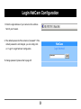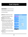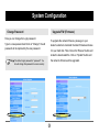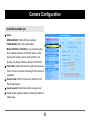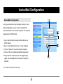
1
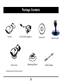
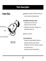
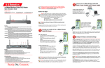
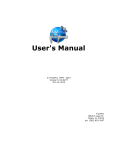
AVerMedia NC100 Digital Network Camera Series User Manual This devicecomplies with Part 1 5 o f F C C r u l e s . Operation is subjecttothefollowing conditions: 1.This devicemaynotcauseharmfulinterference, and. 2.This devicemustaccept any interference that may causeundesired operation. E English Notice 1. Do not drop, puncture or disassemble the camera. 2. Avoid all contact with water . Dry hands before using. 3. Do not expose the camera to high temperature or leave it in direct sunlight. 4. Avoid pressing hard on the camera body. * Use only the AC adaptor supplied by the manufacturer. 1 Contents Getting Started 3 NetCam Manager User Interface 20 Package Contents 4 Parts Description Setting 22 5 Positioning the Camera Login NetCam Configuration 7 23 System Configuration 24 Installation 8 System Information Hardware Installation Wired Connection (NC100) 9 Change Password Upgrade F/W (Firmware) Wireless Connection (NC100W) Network Configuration Connecting DI/DO Device 26 System IP Software Installation Installing the NetCam Manager 12 Configuring the Camera 13 Using Your Camera 16 Taking pictures and Recording AVI Movies 17 WLAN Network Status Wired Link Information WLAN Link Information (for NC100W) Camera Configuration 29 31 Video Configuration Snapshot Digital Output Video Mail Camcorder Zoom Auto-eMail Configuration Auto-eMail Configuration 2 33 Getting Started Package Contents Parts Description Positioning the Camera 3 Package Contents *NC100 12V AC/DC Adapter *NC100 W Mounting Stem * Eachpackage only contains one model. 4 Driver CD Mounting Kit RJ45 Cable Parts Description Front View Antenna: only available for NC100W. The antenna is used to communicate with wireless devices. RDY/ERR LED: (Ready/Error LED's) Flashing green: boot-up and self test. Steady green: power-on and ready. RDY/ERR LED Flashing yellow: auto-email or configuration error. Steady yellow: firmware error. LENS Lens: the camera lens. Ethernet/WLAN LED Ethernet/WLAN LED: Flashing green: indicating Ethernet TX/RX event. *NC100 W Steady green: Ethernet connection indicator. Flashing yellow: the camera is searching for a wireless AP (Access Point) device. Steady yellow: wireless connection indicator. 5 Parts Description Rear View Ethernet Port: this port is for connecting the Ethernet Ethernet Port DC Power Jack: the connector for DC power adaptor. RJ45 cable. DI/DO Pins: the digital input/digital output pins. Please refer to the Installation chapter for more information. C Power Jack Reset Button: press and hold this button to restore the Reset Button DI/DO Pins default settings or the factory firmware. For more information, please refer to the Troubleshooting section. Stem Socket: this socket is for connecting the mounting stem. Stem Socket 6 Positioning the Camera Connecting the Camera to Mounting Stem Align the stem with the camera and place it into the stem socket. Screw mounting stem to the camera Mounting Kit Step 1 Step 2 7 Installation Hardware Installation Software Installation Configuring the Camera 8 Hardware Installation Connecting the Camera to a Network Wired Connection (NC100,NC100W) 1. Connect to Ethernet port : Connect the RJ 45 cable to RJ45 the Ethernet port on your camera, then connect the other end of the cable to a hub or switch. 2. Connect to the AC power adaptor : Connect the AC/DC power adapter to a power outlet and to the camera. 3. Check the Indicator status : Please wait for about 1 minute until flashing LED1 becomes steady green. 9 Power Adapter (USA) Hardware Installation Wireless Connection ( NC100W)) 1. Connect to the AC power adaptor : Connect the AC/DC power adaptor to a power outlet and to the camera. 2. Check the Indicator status : Please wait for about 1 Power Adapter (USA) minute until flashing LED1 becomes steady green. Wireless connection may require an Access Point (AP) device. Please refer to the AP manual for more information on AP settings. 10 Hardware Installation Connecting DI/DO Device The DI/DO feature allows you to connect the camera to various kinds of devices and to extend the utility of the camera. There are 4 pins in total. Pin1 and 2 form a digital input current loop. Its maximum sustainable current is 50mA. Maximum voltage is DC+15V. Normally, R1 is 10K ohms. Pin 3 and 4 form a digital output current loop which is controlled by firmware. You can program the behavior of DO signal through firmware settings (refer to the Setting chapter for more information). Its maximum sustainable current is 50mA. Maximum voltage is DC+15V. Note that a relay is necessary if the connected device requires AC power. Connecting these devices requires certain The following diagram illustrates an example of the technical knowledge. Please consult an expert connections. The window sensor is a N.C sensor. In before making changes to the settings. addition to window sensor, you can also use a door sensor, 11 Software Installation Installing the NetCam Manager (1) Insert the accessory CD into your CD-ROM drive. The (3) Click on "Next". (5) Click on "Next". (4) Check "Yes" and click (6) Click on "OK" to software installation menu should open automatically. (2) Click to start the NetCam Manager Installation. Follow the on-screen instructions, and a shareware program named "WinPcap" will be installed. on "Next". 12 finish the installation. Configuring the Camera 1. Using NetCam Manager to locate the camera in the same LAN segment. By default, NC100W will accept the IP address assigned by a DHCP server. If no DHCP server is present in the network segment, NC100W will automatically set its IP address to 192.168.1.x (x ranges from 1 to 254) with subnet mask 255.255.255.0. You can launch NetCam Manager to locate all cameras within your LAN segment. To Launch NetCam Manager: Click on the "Start" menu and go to "Programs". Then browse to the folder named "NetCam Manager" and run the program. After the main screen appears, the program will scan automatically, or you can manually click on to scan cameras in the same LAN segment. If two or more cameras are using the same host name, you can change their host manes to distinguish them. Please refer to the Setting chapter for more information. Press this button to scan. 13 Configuring the Camera 2. Locating the camera on the Internet. To locate the camera on the Internet, you need to know the IP address of the camera. Launch Internet Explorer and enter the IP address of your camera, and you can use the camera as if it is in the same network segment. Ping a specified IP Address to verify accessibility: Note: If any problem should occur during the PING process, please You can use PING (Packet Internet Groper) utility to check check your network environment or ask an expert for help. whether a specified IP address is accessible by sending a packet to the specified IP address. 1. Start a Command prompt. 2. Type "ping [IP address]". For detailed information on the configuration of 3. Check the reply messages to determine whether the camera, please refer to the Setting chapter. the IP address is reachable. 14 Using Your Camera Taking Pictures and Recording AVI Movies NetCam Manager User Interface 16 Configuring the Camera 2 3. Entering the NetCam Viewer There are two ways to enter the NetCam Viewer: 1. Use NetCam Manager to scan the camera in the Http://192.168.1.1/ same network segment, and double-click on the title bar to enter the Viewer. 2. Start Microsoft Internet Explorer. In the address field, input the IP address of your camera and press "Enter" to access the Viewer. 1 While running NetCam Manager, double-click on a specific camera title bar to enter the NetCam Viewer. If you are entering the Viewer for the first time, you will see this warning message. Press "Yes" to install the software. This is required for the Viewer's operation. 15 Taking Pictures and Recording AVI Movies NetCam Viewer displays real-time video stream captured by the camera. With NetCam Viewer, you can take snapshots or record video clips and e-mail these files to your friends, or you can save video clips in your hard disk. To prevent anyone from directly accessing the Viewer, you can set up a Guest Password. Refer to the Setting chapter for more information. You can e-mail the picture or Taking one single picture. video clip to your friends. Recording a 10-second Snapshot AVI Movie. Video Mail Camera Recorder Recording AVI Movies for longer periods. The file will be saved in your local hard disk. NetCam Viewer 17 Taking Pictures and Recording AVI Movies Snapshot Video Mail 1. Click on 1. Click on 2. The e-mail program will be automatically started and the 2. The camera starts to record a video clip. Click on recorded BMP file is ready to be sent as an attachment. the icon again to stop recording. You can then key in an e-mail address to send the mail. 3. The e-mail program will be automatically started and the recorded video clip is ready to be sent as an attachment. You can then key in an e-mail address to send the mail. 1. Make sure that your PC has an e-mail program installed before using these functions. 2. The maximum recording time for Video Mail is 10 seconds. 18 Taking Pictures and Recording AVI Movies Camera Recorder 1. Click on 2. Press the button and specify a folder and file name to save the file. If you choose to auto-save video clips, you can specify the time interval. For example, a "10" in the minutes field indicates video clips will beautomatically saved to h a r d disk every 10 minutes. The file name will be automatically rendered. 3. Check this box if you want to autosave video clips between intervals. 4. Check this box if you don't want the file size to exceed 640MB. Zoom "Zoom x 1" is the default Viewer setting. Choose "Zoom x 2" or "Zoom x 4" if you need to view the objects in detail. 19 NetCam Manager User Interface NetCam Manager User Interface Access the Login page on Internet Explorer. However, it may be possible that your PC and camera are using IPs that are considered to be in different segments (even though they are actually in the same network segment). If this happens, pressing this button will popup a prompting message asking if you really want to configure the camera settings. If you select "Yes", the following dialogue window will appear: Exit Test Setup Scan There are four buttons on the screen: [Scan]: Press this button to scan all cameras in the same network segment. [Setup]: Normally, pressing this button will launch Internet Explorer and lead you to the Login page, which will then lead you to the NetCam Configuration page provided the correct password is entered. After entering the correct password and pressing "OK", a setup window will popup, as the following: 20 NetCam Manager User Interface [Test]: Press this button to test the throughput readings. The Login password is required to access the throughput test function. NetCam Manager User Interface (continued) Enter password and press "OK". Change settings in this window. You can then make changes and press "OK" to apply these changes to the camera. For more information about these settings, please refer to the Setting chapter. Press "Test". Test result. [Exit]: Press this button to exit NetCam Manager. The default Login password is "password". If the default password is not changed, you can simply press "OK" to enter the setup window. 21 Setting Login NetCam Configuration System Configuration Network Configuration Network Status Camera Configuration Auto-eMail Configuration 22 Login NetCam Configuration 1. Enter the login address of your camera in the address field of your browser. 2. The default password of the camera is "password". If the default password is not changed, you can simply click on " Login" to login NetCam Configuration. To change password, please refer to page 25. 23 System Configuration System Information The System Information screen displays the current status of the camera on the Network. MAC address: the MAC address of your camera's built-in network card. This item cannot be changed. IP address: the camera's IP address. F/W version: the camera's firmware version. HTTP Port: the port number configured to receive data packets from the camera. The default HTTP port number is 80. If you configure a different port number, you must specify the port number in the browser (ex. 192.168.1.1:8080, where 8080 is the port number). An alternative way is to configure your router's NAPT settings. Please refer to the router's user manual for more information. Host Name: host name can be renamed to distinguish different cameras. 24 System Configuration Change Password Upgrade F/W (Firmware) Here you can change the Login password. To upgrade the camera firmware, please go to your Type in a new password and click on "Change"; the old dealer's website to download the latest firmware and save password will be replaced by the new password. it in your hard disk. Then click on the "Browse" button and locate the downloaded file. Click on "Update" button and the camera's firmware will be upgraded. The default Login password is "password". You should change this password to ensure security. 25 Network Configuration System IP By default, the camera is set to receive any IP address assigned by the DHCP server in the same network segment. If you want to assign a static IP to the camera, make sure that the IP is available every time the camera is powered on. To configure a static IP address, click on the item "Via Static Assigned" and then input the IP address, subnet mask, gateway, and DNS server. The following is an example of the settings: IP address: 192.168.1.1 Netmask: 255.255.255.0 Gateway: 192.168.1.254 DNS server: 192.168.1.254 Note that the example may not be suitable for your actual You can assign a static DNS server address even condition. You should consult an expert before making any though the camera is set to receive IP address change to these settings. from a DHCP server. 26 Network Configuration WLAN For NC100W Mode: Infrastructure: In this mode, the camera will try to communicate with an Access Point (AP) device. Ad-hoc: In this mode, the camera will try to establish a peer-to-peer connection with another wireless device. You can choose a proper mode that suits your environment best. ESSID: This is the Network Name used to distinguish one network group from another. This setting is case sensitive, and it should match the ESSID of your target device or the connection will not be established. The default setting "Any" enables the camera to search all possible targets to make a connection. It is advised that These settings are only for wireless connection you keep the default setting under most circumstances. purposes. 27 Network Configuration Encryption (WEP Key): Two levels of encryption WLAN (continued) methods are available - 64bits and 128bits. The Channel: This setting can only be changed in Ad-hoc 128bits method provides more protection, while the mode. In peer-to-peer connection, two associated 64bits standard is more widely supported. After devices must be configured to use the same channel; specifying the encryption method, you can choose otherwise the connection will fail. Channel number either Alphanumeric mode or Hexadecimal mode to ranges from 1 to 14. Due to different regulations, enter the encryption key. Note that the WEP key of applicable channels differ in different areas. See the camera and AP must match, or the connection will fail. following table for reference. The length of key varies according to the encryption mode and method, as the following table shows: Channel 1 - 14 America Japan Channel 1 - 13 Europe (most areas) Channel 10 -11 Spain Channel 10 -13 France Channel 1 - 11 Alphanumeric mode Hexadecimal mode 64 128 64 128 5 letters 13 letters 10 letters 26 letters WEP key index: After enabling WEP encryption, you must set this index value to match that of your Access Point (AP); otherwise the connection cannot be established. 28 Network Status Wired Link Information Port: the port number configured to receive data packets for the camera. The default HTTP port number is 80. IP: the camera's IP address. MAC: the MAC address of the camera's built-in network card. DNS ( Domain Name Service ) Server: the IP address of DNS server. Link Status: displays the Ethernet link status (up or down). Total Tx Packets: the amount of transmitted packets. Total Rx Packets: the amount of received packets. Clear button: press this button to reset the counting of "Total Tx Packets" and "Total Rx Packets". 29 Network Status WLAN Link Information (for NC100W) Port: the port number configured to receive data packets for the camera. The default HTTP port number is 80. IP: the camera's IP address. MAC: the MAC address of the camera's network card. DNS Server: the IP address of DNS server. Link Status: displays the wireless link status (up or down). ESSID: current ESSID setting. CHANNEL: the channel currently used for transmission. Total Tx Packets: the amount of transmitted packets. Total Rx Packets: the amount of received packets. Link Strength: indicates the link strength between the camera and AP device. Clear button: press this button to reset the counting of "Total Tx Packets" and "Total Rx Packets". 30 Camera Configuration Audio/Not available yet Video: QVGA(320x240): VGA with lower resolution. VGA(640x480): this is the default setting. Mixed (320x320 or 160x120): If you select this option, the PC display resolution is 320x320; while on other devices with smaller screens (such as PDA or cell phones), the display resolution will become 160x120. Frame Rate: determines the time length to produce one frame. You can increase the time length if the network is congested. Video Format: NTSC is for America; while PAL is for Pan-Europen areas. Guest assword: determines whether a regular user Needs to enter password before accessing the NetCam Viewer page. 31 Camera Configuration Digital Output Trigger by Digital Input: specify that the digital output signal is triggered upon receiving the digital input signal. You can further specify the duration of effective time in the blank field. On: manually turn on the digital output signal. You can further specify the duration of effective time in the blank field. Off: manually disable the digital output feature. 32 Auto-eMail Configuration Auto-eMail Configuration As long as recipient's e-mail settings are set up in AutoeMail Configuration, you can send e-mails with still pictures attached to the selected recipients. The captured image will be in JPEG format. 1. Key in Sender's Name, Sender's Mail address, and Email Subject. 2. Key in e-mail addresses for one or more recipients. 3. Click on "Select All" or select recipients manually. 4. Click on "OK" to complete Auto-eMail Configuration. 5. Every time the camera receives a DI (Digital Input) signal, this Auto-eMail will be sent with a still picture attached. *Auto-eMail does not send video clips. 33 Glossary 1. IP Address aIP address is an address which is used to locate a network device on TCP/IP network. 2. DHCP aDynamic Host Configuration Protocol (DHCP) provides a framework for passing configuration information to hosts on a TCP/IP network. 3. DNS Server aThe Domain Name System is a distributed database that is used by TCP/IP applications to map between host names and IP addresses, and to provide electronic mail routing information. 4. MAC Address aMAC (Media Access Control) address is a unique hardware number on network. It is used by the Media Access Control sub-layer of DataLink Layer of communication protocol. 5. HTTP aThe Hypertext Transfer Protocol (HTTP) is an application-level protocol with the lightness and speed necessary for distributed, collaborative, hypermedia information system. 6. ESSID aESSID stands for Extended Service Set Identifier. It is used to identify wireless LAN groups. 7. TX aTX stands for transmission. 8. RX aRX stands for reception. 9. NAPT (Network Address Port Translation) aNAPT is a method by which many network addresses and their TCP/UDP ports are translated into a single network address and its TCP/UDP ports. 34 Troubleshooting Q1: How do I restore the camera to the default setting while the RDY LED is flashing yellow light? A1: Step 1. Press and hold down the reset button. Step 2. Plug in the AC/DC adapter. Step 3. Release the reset button immediately when the RDY LED light changes into orange light. Camera will soon be reset. Q2: How do I recover device while RDY LED indicates yellow light? A2: Follow the steps to restore firmware & configuration. Step 1. Press and hold the reset button. Step 2. Plug in the AC/DC adapter. Step 3. When you see the RDY LED indicates steady orange light, don't release the reset button. Release the reset button after the RDY LED light has changed into flashing orange light. The camera will then start restoring firmware. Q3: How can I access my NetCam if my NetCam is connected to internet via an IP sharing router? A3: Please configure NetCam's IP address to router's DMZ item, or configure router's NAPT table to redirect HTTP packet to NetCam's IP address. For example, IP sharing router's network address is "192.168.1.x", and NetCam's IP address is " 192.168.1.123". You can directly configure router's DMZ item to "192.168.1.123". Or, set router to forward IP packet with port 80 to "192.168.1.123" in NAPT table. 35 Troubleshooting Q4: No image shows while accessing NetCam Viewer. A4: The web page hasn't passed Windows Logo testing. Please go to the Internet Explorer and change all settings to default settings. Q5: Is there any limitation on the number of administrators? A5: Only one administrator is allowed. Q6: Is there any limitation on the number of NetCam Viewer? A6: Maximun guests and 1 administrator are allowed to connect at the same time. Q7: Recipients can't receive mails sent by the camera. A7: The mail server may be temporarily down or busy. Please try to send the mail again later. Q8: I would like to configure a static DNS IP, how can I obtain the information of my local DNS server? A8: Please ask your local ISP (Internet Service Provider) for assistance. Q9: The NetCam Viewer display is blank. A9: Please check the security level of your browser. If it is set to High, lower the security level to solve this problem. 36