1
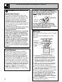
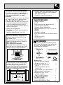
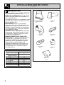
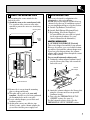
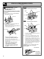
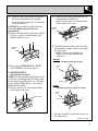
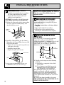
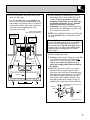
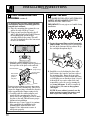
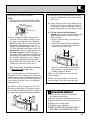
Installation Instructions
Speedcook Oven
Read carefully.
Keep these Instructions.
INSTALLATION INSTRUCTIONS
1
REQUIREMENTS FOR INSTALLATION
Important Safety Instructions
See electrical requirements for proper outlet
installation and grounding of this appliance. The
installer must perform a ground continuity check
on the power outlet box before beginning the
installation to insure the outlet box is properly
grounded. If not properly grounded, or if the
outlet does not meet electrical requirements noted
below, a qualified electrician should be employed
to correct any deficiencies.
CAUTION: For personal safety, remove house
fuse or open the circuit breaker before
beginning installation.
CAUTION: For personal safety, the mounting
surface must be capable of supporting the
cabinet load in addition to the added weight
of this 70 lb. product plus oven loads of up
to 50 lbs., or a total of 120 lbs.
CAUTION: For personal safety, this product
cannot be installed in cabinet arrangements
such as an island or a peninsula. It must be
mounted to both a top cabinet and a wall.
NOTE: For easier installation and personal safety,
it is recommended that two persons install this
product.
Electrical Requirements
Product rating is 240/208 volts AC, 60 Hertz,
30 amps and 6.5 kilowatts. This product must be
connected to an individual properly grounded
branch circuit, protected by circuit breakers or
time delay fuses. Wire size must conform to the
requirements of the National Electric Code or the
prevailing local code for this kilowatt rating. The
outlet box should be located in the cabinet above
the oven. The supply circuit and outlet box should
be installed by a qualified electrician and conform
to all prevailing electrical codes. The wall outlet
receptacle recommended for this appliance is
NEMA # 14-30R and accepts the four prong
grounded plug of this appliance (see Fig. 1 above).
2
WARNING – PLEASE READ CAREFULLY.
FOR PERSONAL SAFETY, THIS APPLIANCE
MUST BE PROPERLY GROUNDED TO
AVOID SEVERE OR FATAL SHOCK.
Fig. 1
NEMA 14-30R
Wall Receptacle
Insure proper
ground exists
before use.
DO NOT UNDER ANY CIRCUMSTANCES,
CUT, DEFORM, OR REMOVE ANY OF THE
PRONGS FROM THE POWER CORD. DO NOT
USE WITH AN EXTENSION CORD.
Mounting Space
This section describes the space you need to install
your oven.
Your oven requires mounting space on a wall
as shown.
Bottom Edge
of Cabinet
Needs to be
30″ or More
From the
Backsplash
Cooking
Surface
16-1/8″
30″
2″
30″
66″ or More
From the
Floor to the
Top of the
Oven
1. A minimum of 30″ between the cabinets is
required for installation. If the space between
the cabinets is greater than 30″, a Filler Panel
Kit may be used to fill in the gap between the
oven and the cabinets. Your Owner’s Manual
contains the kit number for your model.
2. Make sure the bottom edge of the cabinet that
will be above the oven is at least 66″ from the
floor and 30″ from the cooking surface.
3. For easier access to change the hood and range
lamps, the bottom of the oven should be at least
2″ above the range backsplash.
4. If you are going to vent your oven to the outside,
see Section 5 for exhaust duct preparation.
5. When installing the oven beneath smooth,
flat cabinets, be careful to follow the
instructions on the top cabinet template for
power cord clearance.
6. For best installation results, we recommend a
maximum cabinet depth of 12″.
OVERVIEW OF INSTALLATION PROCEDURE
This section gives a brief overview of what you
need to do to install this oven. Read these
entire instructions before you begin
installation.
Before you install this oven, remove the adhesive
tape, if there is any, on the exhaust adaptor,
grease filters and power supply cord.
1. Install an outlet and make sure you meet the
electrical requirements for this installation.
2. Open the installation hardware packets.
Compare it to the hardware list to make sure
you have all the parts.
3. Remove the mounting plate.
4. Check the oven exhaust duct and change it
if required.
5. Attach the mounting plate to the wall.
Your cabinets may have trim that interferes
with the oven installation. You may need to
remove the trim in order to fit the oven in
and to make it level.
The space must be 30″ wide. Remove any
cabinet side trim that interferes with the 30″
space, front or back.
THE OVEN MUST BE LEVEL.
If the cabinets have top trim (front, back or
both), this can be left in place if there is still
enough clearance for proper installation.
6. Hook the slots at the back bottom edge of the
oven onto the 2 lower tabs of the mounting
plate and rotate it up.
7. Attach the oven to the top cabinet.
TOOLS YOU WILL NEED
• Phillips screwdriver
• Pencil
• Ruler or tape measure and straight edge
• Carpenter square (optional)
• Tin snips (in some applications)
• Electric drill with 3/16″, 7/16″, 1/2″ and 5/8″
drill bits
• Hammer
• Stud finder (optional)
• Filler blocks, if needed for top cabinet spacing
• Gloves
• Saw (jig or keyhole)
• Safety goggles
2
PARTS INCLUDED
You will find the installation hardware packed
with the unit. Check to make sure you have all
these parts. The installation hardware (1–7)
should include the following:
1
4
5
2
30″
6
7
3
If you leave the top front trim on, and there is
no back trim, make sure the mounting plate
is positioned down far enough to keep the
oven level. Keep the space between the
bottom of the cabinet and the mounting plate
equal to the height of the top front trim. This
will insure level installation of the oven.
Height of the
Top Front Trim
Back
Wall
Mounting
plate must
be installed
so that the
oven
is level
Hardware List
Quantity
(some extra parts are included)
1. Wood Screws (1/4″ x 2″)
2
2. Toggle Bolts (and wing nuts)
4
1/4″ x 3″
3. Self-aligning Machine Screws
(1/4″ x 3 1⁄4″)
3
4. Nylon Grommet (for metal cabinets)
2
5. Exhaust Adaptor (with damper)
1
6. Metal Screws (1/8″ x 1/2″)
3
(1 black, 2 bronze)
7. Power Cord Strap (plastic)
1
In addition you will need:
Top Cabinet Template
1
Installation Instructions
1
Separately Packed Grease Filters
2
3
INSTALLATION INSTRUCTIONS
(continued)
3
HOOD EXHAUST DUCT
Outside ventilation requires a HOOD EXHAUST
DUCT. Read the following carefully.
EXHAUST CONNECTION: The hood exhaust
has been designed to mate with a standard 31⁄4″
x 10″ rectangular duct.
If a round duct is required, a rectangular-to-round
transition adaptor must be used. Do not use less
than a 6″ diameter duct.
REAR EXHAUST: If a rear or horizontal
exhaust is to be used, care should be taken to
align exhaust with space between studs, or wall
should be prepared at the time it is constructed
by leaving enough space between the wall studs
to accommodate exhaust.
MAXIMUM DUCT LENGTH: For satisfactory
air movement, the total duct length of 31⁄4″ x 10″
rectangular or 6″ diameter round duct should
not exceed 140 equivalent feet.
ELBOWS, TRANSITIONS, WALL AND
ROOF CAPS, etc., present additional resistance
to airflow and are equivalent to a section of
straight duct which is longer than their actual
physical size. When calculating the total duct
length, add the equivalent lengths of all
transitions and adaptors plus the length of all
straight duct sections. The chart below shows
the approximate feet of equivalent length of
some typical ducts.
Duct
A. Rectangular-to-Round
Transition Adaptor
B. Wall Cap
C. 90° Elbow
D. 45° Elbow
E. 90° Elbow
F. 45° Elbow
G. Roof Cap
4
A. Rectangular-to-Round
Transition Adaptor
5 Ft.
B. Wall Cap
40 Ft.
C. 90° Elbow
10 Ft.
D. 45° Elbow
5 Ft.
E. 90° Elbow
25 Ft.
F. 45° Elbow
5 Ft.
Equivalent Length
5 Ft.
40 Ft.
10 Ft.
5 Ft.
25 Ft.
5 Ft.
24 Ft.
G. Roof Cap
24 Ft.
4
REMOVE THE MOUNTING PLATE
The mounting plate comes attached to the
back of the oven.
1. Stand the oven on its control panel side.
Use a portion of the carton or some other
material to protect the outer case from being
damaged.
Mounting Plate
Control
Panel
Side
Mounting
Plate
5
OVEN EXHAUST DUCT
This oven is designed for adaptation to the
following three types of ventilation.
NOTE: This oven is shipped assembled for top
exhaust. Select the type of ventilation required
for your installation and proceed to that section.
A. Outside Top Exhaust (Vertical Duct)
B. Outside Back Exhaust (Horizontal Duct)
C. Recirculating (Non-Vented Ductless)
A Charcoal Filter Accessory Kit is required
for the non-vented exhaust. (See your
Owner’s Manual for the kit number.)
ADAPTING OVEN BLOWER
A. OUTSIDE TOP EXHAUST (Vertical)
This oven is shipped assembled for top exhaust.
However, if you have a recessed cabinet bottom,
you will need to install the exhaust adaptor now.
If you have a flat bottom cabinet, the exhaust
adaptor will be installed later through the cutout
in the cabinet bottom.
For recessed bottomed cabinets only:
1. Position the exhaust adaptor (hardware item 5)
over the blower plate, hinge side toward the
back of the oven.
Exhaust
Adaptor
Back
of Oven
Control Panel Side
2. Remove the 2 screws from the mounting
plate as shown and discard.
3. This plate will be used as the rear wall
template. (It will be used to locate and mark
the mounting holes on the rear wall.)
4. Locate exhaust adaptor, grease filters and
hardware packet.
5. At this point, remove any adhesive tape
(if there is any), on the exhaust adaptor, the
grease filters and the power supply cord.
2. Attach the exhaust adaptor to the blower plate
using the 2 bronze metal screws provided
(hardware item 6).
3. Proceed to the PREPARATION OF TOP
CABINET section. (See page 8.)
For flat bottomed cabinets, proceed to the
PREPARATION OF TOP CABINET section.
5
INSTALLATION INSTRUCTIONS
(continued)
5
OVEN EXHAUST DUCT (continued)
B. OUTSIDE BACK EXHAUST
(Horizontal Duct)
This oven is shipped assembled for top exhaust.
Use the following steps to change it for outside
back exhaust.
1. Remove and save the screws that hold the
blower plate to the oven.
BEFORE:
Fan Blade Openings Facing Up
Blower
Unit
End B
End A
Blower Plate
Grooves
AFTER:
Fan Blade Openings Facing Back
2. Slide the blower plate back from under its
retaining flange and lift it off.
• Remove and save the screw that holds the
blower motor to the oven.
Grooves
End A
Blower
Unit
End B
Retaining Flange
• The wires should be routed in the grooves
of the motor frame.
3. • Carefully pull out the blower unit.
• The wires will extend far enough
to allow you to adjust the blower unit.
• Turn the blower unit end-over-end.
• Reroute the wires through the grooves on
the other side.
• Roll the blower unit so that the fan
blade openings are facing out the
back of the oven. The blower
unit exhaust openings should match
the exhaust openings on the rear of
the oven.
4. • Locate the two “knockout” plates, on the
rear oven panel, near the top of the oven.
• Using tin snips, carefully cut the web area
from the two holes side-by-side (that secure
the knockouts to the oven). Cut all four
webs on both rear knockouts; this will allow
the ventilation fan airflow to exhaust out
the rear of the oven.
CAUTION: Be sure to trim the sharp edges
from the openings after removing the
knockout plates.
Oven Rear Panel
Snip all 4 webs
on each knockout
panel and remove
the metal knockouts
for rear airflow.
6
5. • Guide the wires into the duct as you place
the blower unit back into the opening.
• Secure the blower unit to the oven with the
screw from Step 2.
CAUTION: Do not pull or stretch the blower
unit wiring. Make sure the wires are
not pinched.
6. Replace the blower plate in the same position
as before, under its retaining flange, and
attach it with the screws.
2. • Slide the blower plate back from under its
retaining flange and lift it off.
• Remove and save the screw that holds the
blower motor to the oven.
Retaining
Flange
3. Carefully pull out the blower unit. The wires
will extend far enough to allow you to adjust
the blower unit.
• Roll the blower unit so that the fan
blades are facing towards the front
of the oven.
Retaining
Flange
BEFORE:
Fan Blade Openings Facing Up
7. Proceed to the PREPARATION OF THE
TOP CABINET section. (See page 8.)
C. RECIRCULATION
(Non-Vented, Ductless)
NOTE: The exhaust adaptor with damper is not
needed for recirculating models. You may want
to save them for possible future use. (You must
use the Charcoal Filter Kit. See your Owner’s
Manual for kit number.)
1. Remove and save the screws that hold the
blower plate to the oven.
Blower
Unit
Grooves
AFTER:
Fan Blade Openings Facing Front of Oven
Blower
Unit
Blower Plate
Grooves
• The wires should be routed in the grooves of
the motor frame.
(continued next page)
7
INSTALLATION INSTRUCTIONS
(continued)
5
OVEN EXHAUST DUCT (continued)
4. • Guide the wires into the duct as you place
the blower unit back into the opening.
• Secure the blower motor to the oven
with the screw from Step 2.
CAUTION: Do not pull or stretch blower unit
wiring. Make sure wires are not pinched.
5. Replace the blower plate in the same position
as before, under its retaining flange, and
attach it with the screws.
Retaining
Flange
IMPORTANT—When installing the exhaust
blower in recirculation position, use Charcoal
Filter Accessor y Kit available from your
appliance dealer.
6
PREPARATION OF TOP CABINET
You need to drill holes for the top support
screws and a hole large enough for the power
cord to fit through.
• Read the instructions on the top cabinet
template.
• Tape it underneath the top cabinet.
• Drill and cut out the appropriate holes,
following the instructions on the template.
7
ATTACH THE MOUNTING PLATE
TO THE WALL
6. Install the Charcoal Filter. See the Owner’s
Manual for the Charcoal Filter Accessory Kit
needed for this model.
• Remove the 2 screws on the top of the case
and remove the grille.
• Install the charcoal filter.
• Replace the grille and 2 screws.
Your oven needs to be mounted against and
supported by a flat, vertical wall. Wall
construction should be a minimum of 2″ x 4″ wall
studding and 3/8″ or more thick drywall or
plaster/lath. The oven must be attached to a
minimum of one 2″ x 4″ wall stud.
Usually
16″ or 24″
2″ x 4″
Wall Stud
Charcoal Filter
Grille
7. Proceed to the PREPARATION OF TOP
CABINET section. (See the next step.)
8
Drywall or
Plaster/Lath
1. Find the studs, using one of the following
methods:
A. Stud finder—a magnetic device which
locates nails.
B. Use a hammer to tap lightly across the
mounting surface to find a solid sound.
This will indicate a stud installation.
After locating the stud(s), the center can be
found by probing the wall with a small nail to
find the edges of the stud and then placing a
mark halfway between the edges. The center
of any adjacent studs should be 16″ or 24″ from
this mark.
2. Draw a line down the middle of the studs.
THE OVEN MUST BE CONNECTED TO AT
LEAST ONE WALL STUD.
3. Draw a vertical line on the wall at the center
of the 30″ wide space.
Use the mounting plate as the template for
the rear wall. Place the mounting plate on the
wall, making sure that the tabs are against the
bottom of the cabinet. Line up the notch and
center line on the mounting plate to the
center line on the wall.
3/16 ″ Hole on Studs
5/8 ″ Hole on Drywall Only
Minimum 66″
From the Floor
For Outside
Back Exhaust
Only
Draw
Center Line
A
B
Center Line
C
D
E
Tab
NOTE: Draw a fifth circle inside area E, through
one of the bottom holes to match the location
of a stud.
For outside back exhaust: The oven requires
a rear wall cutout opening for the rear wall duct
and the exhaust adaptor must be attached to
the mounting plate. See the next page on how
to prepare the rear wall cutout opening and the
exhaust adaptor/mounting plate for outside
back exhaust.
Draw Lines
on Studs
Mounting
Plate
4. While holding the mounting plate with one
hand, draw circles on the wall at holes A, B,
C and D. Four holes must be used for
mounting. If the holes are not used, the
installation will not be secure. Installer
must use these holes for proper
installation. Use toggle bolts through these
holes unless one of them lines up with a stud.
Use a wood screw for studs.
Set the mounting plate aside.
5. Drill holes on the circles. If there is a stud, drill
a 3/16″ hole for wood screws. If there is no
stud, drill a 5/8″ hole for toggle bolts. Make
sure to use at least 1 wood screw in a
stud, and 4 toggle bolts in the dr ywall or
the plaster.
6. Attach the plate to the wall. To use toggle
bolts: Remove the toggle wings from the
bolts. Insert the bolts into the mounting plate
and replace the toggle wings to 3/4″ past the
bolt ends. Insert the toggle wings into the
holes in the wall to mount the bracket. You
may pull forward on the bracket to help in
tightening the toggle bolts. Tighten all bolts.
Tab
Mounting
Plate
Space More Than Wall Thickness
Toggle Wings
Toggle Bolt
Bolt
End
Wall
(continued next page)
9
INSTALLATION INSTRUCTIONS
(continued)
7
ATTACH THE MOUNTING PLATE
TO THE WALL (continued)
8
To prepare the rear wall cutout opening
and exhaust adaptor/mounting plate for
outside back exhaust:
1. Place the mounting plate against the rear
wall as described in Step 7, item 3.
2. Using a pencil, put dots through slots F
and G, and through holes H and I. Remove
the mounting plate and draw lines
extending through the points. This will
give the location and size of the box cutout
for the rear wall duct.
F
G
H
I
MOUNT THE OVEN
FOR EASIER INSTALLATION AND PERSONAL
SAFETY, WE RECOMMEND THAT TWO
PEOPLE INSTALL THIS OVEN.
IMPORTANT: Do not grip or use handle during
installation.
1. Locate the grease filters packed separately
and set aside. Thread the power cord through
the hole in the bottom of the top cabinet. Keep
the cord tight throughout Step 2.
• Attach the exhaust adaptor to the rear
mounting plate by sliding it into the guides at
the top center of the plate on the wall side.
Damper
(hinge side up)
Exhaust Adaptor
Mounting Plate
(wall side)
Slide exhaust
adaptor into
guides on
rear panel.
Locking
Tabs
Guides
Push in securely until it is past the top locking
tabs and in the lower locking tabs. Take care to
assure the damper hinge is installed so that it is
at the top and that the damper swings freely.
• Carefully guide the exhaust adaptor, now
attached to the mounting plate, into the
house duct, before using the screws to attach
the plate to the wall. This will assure proper
alignment for installation.
• Return to step 7, item 5 (page 9) to continue.
After completing the installation of the
mounting plate, again check the rear
damper for free movement to assure it
will operate properly.
10
2. Install the oven by hooking the slots at the
back bottom edge onto the two lower tabs of
the mounting plate. Rotate the front of the
oven up against the cabinet bottom and using
a self-aligning screw (hardware item 3) insert
it through the top center cabinet hole and
temporarily secure the oven by turning the
screw two full turns. (It will be completely
tightened later.) Be sure to keep power
cord tight.
NOTE: If your cabinet is metal, use the
nylon grommet around the power cord
hole to prevent cutting of the cord.
3. Attach the oven to the top cabinet.
NOTE:
1. You’ll need to use a filler block if the cabinet
front hangs below the cabinet bottom shelf.
Cabinet Front
Cabinet Bottom Shelf
Filler Block
4. Install the grease filters and remove the tape
from the cooktop lamp covers on the bottom
of the oven.
5. Secure the power cord to the cabinet wall, as
desired to keep excess length out of the way.
Use the power cord strap (hardware item 7)
and the black metal screw (hardware item 6).
Minimum 3/16″
Oven Top
2. If your cabinet front hangs more than 23⁄4″
below the cabinet bottom, you may need to
use longer screws than the ones provided
with this product. The screws provided with
this product (hardware item 3) are selfaligning, large-head machine screws 1⁄4″ dia.,
31⁄4″ long, with SAE 28 threads per inch. It is
important that you use replacement screws
just long enough to attach the product to
the cabinet. The length can be determined by
measuring the height of the overhang from
the top of the cabinet floor to the bottom of
the overhang and adding one inch to that
length. This will be the length of the 1⁄4″ SAE
28 threads per inch screws you need.
6. For top exhaust on flat bottomed
cabinets, open the top cabinet and attach the
exhaust adaptor to the oven through the
cabinet bottom.
• Remove and discard the 2 screws for the
blower plate.
• Position the exhaust adaptor (hardware
item 5) over the blower plate, hinge side
toward the back of the oven.
This is necessar y to allow for clearances
of internal parts of your oven.
Insert 2 self-aligning screws (hardware item 3)
through the outer top cabinet holes. Tighten the
center screw completely and then the outer two
screws to the top of the oven. (While tightening
screws, lift the front side of the oven and push
toward the wall.)
You will also need to use washers 3⁄4″ dia. to fit
the screws you purchase. This will prevent the
screw heads from pulling through the bottom of
the cabinet when tightening during installation.
• Attach the exhaust adaptor to the blower
plate using the 2 bronze metal screws
provided (hardware item 6).
Make sure the damper moves freely in the
exhaust adaptor.
Pull the house duct down to connect to the
exhaust adaptor. Tape duct using duct tape.
9
INSTALLATION CHECKLIST
1. Make sure the oven has been installed
according to instructions.
2. Remove all packing material from the oven.
3. Replace house fuse or turn breaker back on.
4. Plug power cord into outlet.
5. Read the Owner’s Manual.
6. KEEP INSTALLATION INSTRUCTIONS
FOR THE LOCAL INSPECTOR’S USE.
11
Part No. 164D3370P068
Pub. No. 49-40068-1
3828W5U0050
8-99
JR
Printed in Korea