1
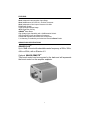
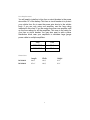
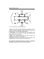
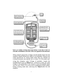
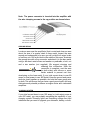
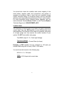
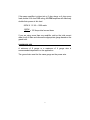
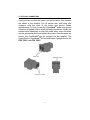
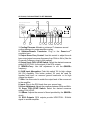
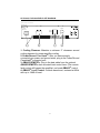
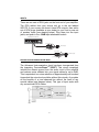
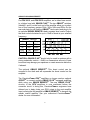
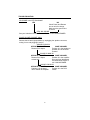
AMPLIFIER MODELS
DCX 300.2
DCX 500.2
TABLE OF CONTENTS
Congratulations . . . . . . . . . . . . . . . . . . . . . . . . . . . . . . . . . . . . . . .2
Service . . . . . . . . . . . . . . . . . . . . . . . . . . . . . . . . . . . . . . . . . . . . . .2
Caution . . . . . . . . . . . . . . . . . . . . . . . . . . . . . . . . . . . . . . . . . . . . .2
Features . . . . . . . . . . . . . . . . . . . . . . . . . . . . . . . . . . . . . . . . . . . . .3
QBASS PLUS Specifications . . . . . . . . . . . . . . . . . . . . . . . . . . . .3
Specifications . . . . . . . . . . . . . . . . . . . . . . . . . . . . . . . . . . . . . . . .4
Amplifier Status LEDs . . . . . . . . . . . . . . . . . . . . . . . . . . . . . . . . . .6
Tools/Parts for Installation . . . . . . . . . . . . . . . . . . . . . . . . . . . . . . .7
Wiring . . . . . . . . . . . . . . . . . . . . . . . . . . . . . . . . . . . . . . . . . . . . . .7
Ground Wiring . . . . . . . . . . . . . . . . . . . . . . . . . . . . . . . . . . . . . . . .9
Charging System . . . . . . . . . . . . . . . . . . . . . . . . . . . . . . . . . . . . . .9
Current Draw . . . . . . . . . . . . . . . . . . . . . . . . . . . . . . . . . . . . . . . .10
Power Wire Size . . . . . . . . . . . . . . . . . . . . . . . . . . . . . . . . . . . . .11
PowerLock Connectors . . . . . . . . . . . . . . . . . . . . . . . . . . . . . . . .12
DCX 300.2, DCX 500.2 Front Plate Diagram . . . . . . . . . . . . . . .13
DCX 300.2, DCX 500.2 End Plate Diagram . . . . . . . . . . . . . . . .14
Inputs . . . . . . . . . . . . . . . . . . . . . . . . . . . . . . . . . . . . . . . . . . . . . .15
Advanced Instrumentation Input . . . . . . . . . . . . . . . . . . . . . . . . .15
QBASS PLUS/QBASS Remote . . . . . . . . . . . . . . . . . . . . . . . . . .16
TC-X Crossover . . . . . . . . . . . . . . . . . . . . . . . . . . . . . . . . . . . . . .17
Crossover Detent Chart . . . . . . . . . . . . . . . . . . . . . . . . . . . . . . . .18
Adjusting Input Gain . . . . . . . . . . . . . . . . . . . . . . . . . . . . . . . . . .19
High Mass Internal Heatsink . . . . . . . . . . . . . . . . . . . . . . . . . . . .19
AP-IV Protection Circuit . . . . . . . . . . . . . . . . . . . . . . . . . . . . . . . .19
Troubleshooting . . . . . . . . . . . . . . . . . . . . . . . . . . . . . . . . . . . . . .20
1
CONGRATULATIONS
Thank you for choosing PrecisionPowerTM audio equipment.
Designed and engineered in the USA, this product combines
innovative technology with the finest materials to consistently deliver
Absolutely State of the Art™ performance, sound quality, reliability,
and value. This PrecisionPowerTM product reflects our commitment
to offer you unparalleled performance and quality for years of
dependable service and listening enjoyment.
SERVICE
Do not attempt to service PrecisionPowerTM products yourself.
Performing maintenance on your audio equipment will void the
warranty. Many parts of the PrecisionPowerTM product are custom
built to our specifications. Our factory parts are not made
available to anyone else nor are they for sale. Our goal is to
make sure that your PrecisionPowerTM product will always sound as
good as the day it was purchased. Contact your Authorized
PrecisionPowerTM Dealer about obtaining any warranty service
through PrecisionPowerTM. (See the Warranty on the outside of the
back cover).
CAUTION
Extended use of a high powered audio system may result in hearing
loss or damage. While PrecisionPowerTM systems are capable of
“Concert Level” volumes with incredible accuracy, they are also
designed for you to enjoy at more reasonable levels all of the sonic
subtleties created by musicians. Please observe all local sound
ordinances.
2
FEATURES
New! Advanced Instrumentation Input Stage.
New! 24dB/Octave; HP/LP/FULL; 30-4kHz Crossover.
New! Independent Line Output Crossover 30-4kHz
PWM Power Supply
Triple Darlington Output Stage.
AP-IV Protection Circuity
QBASSTM Bass Boost
High Voltage Input Capability with -12dB Attention Switch.
Gold Plated RCA Input and Output Connectors.
PowerLockTM Speaker and Power Wire Connectors.
2 Yr Warranty; if installed by an Authorized PrecisionPower Dealer.
QBASS PLUS SPECIFICATIONS
QBASS PLUSTM
Up to 18dB of boost with selectable center frequency at 30Hz, 36Hz,
44Hz or 60Hz, with a Q-factor of 2.
Optional QBASS REMOTETM
This boost control can be mounted in the dash and will supersede
the boost control on the amplifier endplate.
3
SPECIFICATIONS
Power Ratings
MODEL
DCX 300.2
DCX 500.2
4 ohm
2 X 75
2 X 125
2 ohm
2 X 150
2 X 250
4 ohm MONO
1 X 300
1 X 500
All power ratings given above are tested at 12.5V; 4 ohms; 20Hz - 200Hz.
General Specifications
Load Impedance (Stereo)
Load Impedance (Bridged)
Input Topology
Conversion Efficiency
Frequency Response
Linear Bandwidth
S/N Ratio
Input Sensitivity
RCA Output Jacks
Input Impedance
Supply Voltage
Damping Factor
Slew Rate
Crossovers Type/Range
Crossover Slope
QBass
Protection Functions
2–8 ohms
4–8 ohms
Balanced differential
>50% @2 ohms max power
20Hz–20kHz ±0.25dB
10–50kHz ±3dB (300.2)
>110dB
150mv - 12 Volts RMS
HP/LP/Full; 30Hz to 4kHz
20,000 Ohms
9–16 Volts
>250 (300.2) 300 (500.2)
>20V/µs
HP—off/12dB switch 30Hz to 4kHz
LP—off/12dB switch 30Hz to 4kHz
12dB/octave
Variable 0 to +12dB boost @ 40Hz
Short and thermal
4
Fuse Requirements
You will need to install an in-line fuse or circuit breaker in the power
wire within 18” of the battery. This fuse or circuit breaker is to protect
your vehicle from fire in case the power wire shorts to the vehicle
body. If you are only using one amplifier, use the fuse rating
indicated in this chart. If you are using more than one amplifier, add
up the fuse ratings for all the amplifiers. This sum is the rating for
your fuse or circuit breaker. You may also want to add a power
distribution block near your amplifiers to distribute large gauge
power cable to multiple amplifiers.
Amp
Fuse
DCX 300.2
35 A
DCX 500.2
50 A
Dimensions
Length
Width
Height
DCX 300.2
24-¾”
10-½”
2-¾”
DCX 500.2
27-3/8”
10-½”
2-¾”
5
AMPLIFIER STATUS LEDS
3
SHORT PROTECT
POWER
4
THERMAL PROTECT
CLIP OUT
1
2
The LEDs provide the following indications:
1. Power - This LED illuminates RED when the amplifier power is
turned on with the remote input (output muted). After a short time
delay this LED will turn GREEN (amplifier ready).
2. Clip Output - This LED illuminates RED on the peaks of the
output signal when the peaks are too high. This clipping causes
audible distortion in the speakers.
3. Short - This LED illuminates RED on a short condition. The
amplifier will turn off and try to turn back on.
4. Thermal - This LED illuminates RED on a thermal condition. The
amplifier will turn off and turn back on in a minute or so.
Note: Read the AP-IV Protection Circuit section for additional
information regarding Short and Thermal protection.
6
TOOLS/PARTS FOR INSTALLATION
NOTE: TOOLS ARE NOT SUPPLIED.
Small flat blade screwdriver
Phillips screwdriver (#2 or medium sized)
Wire cutters
Wire strippers
4 - #6 round head screws, and 1 - #8 sheet metal screw. (or nut, bolt,
flat washer, star washer) (see details)
2 - Ring connectors (large enough to accommodate your method of
grounding)
In-line fuse or circuit breaker
Power and ground wire
Speaker wire - 12-16 gauge
Grommets (sized to work with the power wire you plan to use in your
installation)
Tube of silicone sealant
WIRING
Before beginning, disconnect the negative (-) terminal of the battery
prior to connecting the amplifier to the positive (+) 12V terminal to
prevent a short to ground and potential damage to wiring and
equipment. Some vehicle radios have an anti-theft feature where
when the radio is removed from 12V the radio will no longer function
and must be code reset.
7
Note: The cables running from the battery to the rear of the car
should be installed on the side of the car opposite to the antenna.
When using 16 gauge wire or larger, run the speaker wires from the
amplifier location through the vehicle to the speakers. Observe the
same precautions for routing these wires that you followed for
running the power and remote turn on wires. Cut off excess and,
using wire strippers, strip 1/4-inch of insulation. Locate the
speaker/remote turn-on PowerLockTM connector. Loosen the outer
screws on the underside of the connector. Insert the speaker leads
into the end. Check to be sure you've maintained proper polarity
before securing each wire, and plug the PowerLockTM into the
amplifier.
8
Note: The power connector is inserted into the amplifier with
the wire clamping screws in the up position as shown below.
GROUND WIRING
Locate an area near the amplifier(s) that is metal and clean an area
about the size of a quarter down to bare metal. Inspect the area
around and underneath to be sure you will not drill into wires, brake
or fuel lines, etc. Drill a pilot hole in the middle of this area. Terminate
the ground wire with a ring connector and attach it to the bare metal
using a #8 sheet metal screw and washer or preferable, a bolt, nut
and a star washer. (not supplied). We suggest crimping and
soldering this connection. After the
connection is complete, coat the area
(on both sides) with silicone or some
similar material to prevent rust from
developing on the bare metal. If your total current draw is over 80
amps (or total power is over 500 watts). Keep the ground and power
wires as close together as possible, and use the same gauge wire
for both. This will ensure that you have a good ground path, and may
eliminate such potential problems as engine noise and overheated
amplifiers.
CHARGING SYSTEM
If your total current draw is over 100 amps (or total output power is
over 600 watts), you are probably exceeding the capability of your
charging system. Dimming lights and fluctuating voltage are solid
indicators that you need to upgrade your alternator, battery, or both.
9
You should also check the condition and current capacity of the
stock battery negative cable and connections, and replace or
upgrade as necessary. Keep in mind that your amplifiers simply
convert electrical energy to acoustical energy, and any electrical
deficiency will compromise the performance of your sound system.
For more information about charging system upgrades, see you
local authorized PrecisionPowerTM Dealer or call PrecisionPowerTM
Technical Support at 1-800-62POWER x2033.
CURRENT DRAW
The following is a basic formula to be used as a guide to determine
current draw. Your new DCX amplifier is more efficient than most
other amplifiers. This formula is to be used as a guideline. Using wire
of a larger gauge can only improve the current transfer of your
system. Do NOT use smaller wire gauge.
Total RMS output X 1.5 = Total Input Wattage
Total Input Wattage = Current Draw (in Amps)
Supply Voltage
Example: A DCX amplifier has two channels at 125 watts per
channel RMS rating into 4 ohms (125X2 = 250 watts).
You would use the formula in the following way:
500 W X 1.5 = 750 watts
750W = 62.5 Amps total current draw
12V
10
If the same amplifier is driven into a 2 ohm stereo or 4 ohm mono
load, double it’s 4 ohm RMS rating. All DCX amplifiers will effectively
double their power at this load.
500W X 1.5 X2 = 1500 watts
1500W = 125 Amps total current draw
12V
If you are using more than one amplifier, add up the total current
draw for all of them and choose the appropriate gauge based on the
grand total.
POWER WIRE SIZE
A minimum of 8 gauge or a maximum of 4 gauge wire is
recommended dependent on the application.
The ground wire must be the same gauge as the power wire.
11
POWERLOCK CONNECTORS
Once you have run both the power and ground wires, then connect
the cables to the amplifier. Cut off excess wire, and using wire
strippers, strip the ends of the power and ground cables
approximately 1/4 inch. Locate the PowerLockTM power and ground
connector (supplied). With a small flat blade screwdriver, loosen the
screws before attempting to insert the cable wires. Insert the wires
into the appropriate hole, and tighten the screws. Once the wires are
secure, the PowerLockTM may be plugged into the amplifier. The
Power/Ground PowerLockTM will accommodate 4 gauge wire for the
DCX 300.2, and DCX 500.2.
12
DCX 300.2, DCX 500.2 FRONT PLATE DIAGRAM
12
11
DC X 300.2 DC X 500.2
FrontPanel
R
R
BR ID G E
-
+
O U TPU T XO VER
XO VER
G AIN
FR EQ Q BASS ATT
LP
L
R - R + R EM
1
2
L+
L-
30
LP
40k
M IN
O U TPU T FR EQ FU LL H P
3
4
2
5
1
M AX
-12dB
6
7
30 40k
L
IN TPU T FR EQ FU LL H P
8
9
10
1. Cooling Plenums: Maintain a minimum 2” clearance around
cooling plenums for proper amplifier cooling.
2. Speaker/Remote Connector: Plug in the PowerLockTM
connector here.
3. Output Xover Freq. Control: Use this control to adjust the sub
bass output signal crossover frequency from 30Hz to 4kHz. (See the
Crossover Frequency chart in this manual).
4. Output Xover FULL/LP/HP Switch: Select the desired crossover
setting HP/LP/FULL for the signal of the RCA outputs.
5. QBASSTMFreq.: Use this adjustment to set the QBASSTM
frequency.
6.-12dB Input Attenuation: Push this switch ‘IN’ for high voltage
(4V-12V) capability. This button pushed ‘IN’ must be used for
speaker level input on common ground head-units or for high
voltage line drivers.
7. Gain: Use this control to match the output level of the source unit
to the amplifier.
8. Input: Plug in the RCA leads from your source here.
9. Xover Adjustment: Adjusts the crossover between 30Hz and 4kHz.
10. Xover FULL/LP/HP Switch: Select the desired crossover
setting FULL/LP/HP.
11. QBass: Adjusts the amount of boost provided by the QBASSTM
circuit.
12. RCA Outputs: RCA outputs provide HP/LP/FULL 30-4kHz
signal to another amplifier.
13
DCX 300.2, DCX 500.2 END PLATE DIAGRAM
DC X 300.2 DC X 500.2
End Panel
QBASS
QBASS
REMOTE
+16
1
2
3
0
4
1. Cooling Plenums: Maintain a minimum 2” clearance around
cooling plenums for proper amplifier cooling.
2. Power/Ground PowerLockTM: After you have securely
connected your power and ground wires, plug in the Power/Ground
PowerLockTM connector here.
3. QBASS REMOTETM: Plug in the data cable from the optional
QBASS REMOTETM dash mounted level control here. (The remote
level control will bypass the amplifier’s on board QBASSTM control.
4. QBASSTM Level Control: Controls bass boost, centered at 40Hz
with up to 18dB of boost.
14
INPUTS
There are two sets of RCA jacks on the front end of your amplifier.
The RCA cables from your source unit go in the set labeled
INPUTS. If your source unit doesn’t have RCA outputs, then add a
set of RCA plugs (available at your dealer) to your front or rear set
of speaker leads (see drawing below). Plug them into the input
jacks, and push in the -12dB input attenuation switch.
SOURCE Headunit
eject
BASS
LEFT
1
2
5
6
3
4
7
8
Trk 1
TREBLE
BALANCE
VOLUME
TRACK
RIGHT
FOWARD
PPI
MAR
KET
ING
DPT
REVERSE
(+) Positive
LEFT input
(-) Negative
(+) Positive
RIGHT input
(-) Negative
ADVANCED INSTRUMENTATION INPUT
The Advanced Instrumentation Input has been incorporated from
the legendary PrecisionPowerTM 2500F1. This circuit completely
isolates the chassis ground from the audio circuit of the amplifier
and reduces noise radiated into your signal cables by up to 40dB.
This is equivalent to a noise reduction of approximately one hundred
times what the noise level would be without this circuitry. It provides
all the benefits of a true balanced line without the need of any
special cables (see diagram below). This type of input works with
any conventional RCA cables.
15
QBASS PLUS/QBASS REMOTE
On DCX 300.2, and DCX 500.2 amplifiers, we’ve taken bass control
to a higher level with QBASS PLUSTM. The two QBASSTM switches
(labeled 1 and 2) on the front end of the amplifier allow you to select
one of four frequency centers 30Hz, 36Hz, 44Hz and 60Hz. On the
rear end plate you will find the QBASSTM level control and plug-in for
an optional QBASS REMOTETM dash mounted level control. Adjust
the level control clockwise for up to +18dB of boost at your selected
frequency.
QBASSTM Settings
1
2
Freq.
IN
IN
30Hz
IN
OUT
36Hz
OUT
IN
44Hz
OUT
OUT
60Hz
CAUTION: QBASS PLUSTM should only be used in systems with a
strong subwoofer section. +18dB is a tremendous amount of bass
boost and may damage your speakers or create excessive distortion
if abused.
The optional QBASS REMOTETM: This boost control can be
mounted in the dash and will supersede the boost control on the
endplate.
The PrecisionPower DCXTM amplifiers no longer need an optional
QPORTTM to connect multiple QBASS PLUSTM equipped amplifiers
while using one QBASS REMOTETM. The new QBASS PLUSTM
circuitry in the DCX amplifiers is now positioned before the
crossover circuit. In doing this, PrecisionPowerTM engineers have
allowed you to daisy chain your RCA output to the next amplifier
input, causing the first amplifier’s QBASS REMOTETM to become the
master control amplifier. See your authorized PrecisionPowerTM
dealer for more information!
16
TC-X CROSSOVER
Your new DCX amplifier has a TC-X Crossover (Total Control Xover®) 30Hz-4kHz (see this guide for Crossover Chart).12dB per
octave phase correlated crossover built-in to provide superior
system flexibility without the added expense and installation of an
outboard crossover. The speaker outputs of your amplifier are high
pass, low pass, or all-pass according to the HP/LP/FULL switch on
the front endplate. You would choose low pass (middle position of
switch) to use this amplifier for subwoofers, choose high pass (left
position of switch), or full (right position of switch) to use this
amplifier for full range speakers.
The RCA outputs are controlled by a separate HP/LP/FULL switch,
and are always independent of the speaker output crossover. As
well as being able to independently select HP/LP/FULL, your new
DCX amplifier allows independent selection of frequencies from
30Hz-4kHz (see Crossover Detent Chart in this guide).
DCX 300.2/500.2
Speaker Output - 12dB/Octave, Detented HP/LP 30Hz-4kHz
Low Level Output - 12dB/Octave, Detented; HP/LP
QBASS PLUSTM - up to 18dB @ 30, 36, 44, 60Hz
17
CROSSOVER DETENT CHART
Detent #
1
2
3
4
5
6
7
8
9
10
11
12
13
14
15
16
17
18
19
20
21
22
23
24
25
26
27
28
29
30
31
32
33
34
35
36
37
38
39
40
41
Low Pass
Frequency (Hz)
@ -3dB
28
28
30
30
30
32
34
36
38
42
46
50
52
54
60
66
76
88
100
116
136
144
168
198
240
286
310
340
380
424
484
576
632
748
932
1076
1428
1700
2436
2830
2980
18
High Pass
Frequency (Hz)
@ -3dB
52
52
52
56
56
60
64
72
76
80
88
92
100
116
132
148
168
192
216
244
284
348
404
468
512
564
624
700
800
932
1036
1144
1300
1504
1812
2196
2840
4116
4540
4728
4728
ADJUSTING INPUT GAIN
1. Adjust all amplifier input gain controls to just above minimum
sensitivity (fully counterclockwise).
2. Using the cleanest music source (CD) playing, turn up the head
unit source volume until you can hear distortion. Now turn it down a
bit until you cannot hear the distortion (usually just below full
volume).
3. Increase the amplifier gain (clockwise) until the onset of audible
distortion. Then decrease the gain to the point just before the
distortion starts. This setting minimizes background noise and
prevents overload.
4. Repeat step 3 for any remaining independently controlled
amplifiers (rear and subwoofer gain controls) in the system.
HIGH MASS INTERNAL HEATSINK
The unique heatsink on your DCX amplifier has been designed with
fins on the inside of the aluminum extrusion. This allows for the
transfer of heat from the circuitry to the heatsink fins and out through
the vents in the endplates. Be sure you provide ample space around
the amplifier for cooling: at least 2” on all sides.
AP-IV PROTECTION CIRCUIT
Short Circuit Protection engaged: The DCX amplifiers will turn off
and try to come back on immediately. The amplifier will cycle like this
indefinitely with “blips” of sound each time. If this is the case, check
your speakers and wiring for low impedance and short circuits.
Thermal Protection engaged. The DCX amplifiers will turn off and
after a minute or so will come back on. In this case, ensure that there
is nothing blocking the normal convection airflow of the amplifier. No
obstruction should be within 2” of the amplifier on all sides.
Note: Low battery voltage will cause the amplifier to run
warmer and possibly damage the amplifier.
19
TROUBLESHOOTING
NO SOUND Is the LED illuminated?
YES
NO
Check Power and Remote
turn-on wire for voltage.
Make sure the ground wire
is secure.
STILL NO SOUND
See your Authorized PrecisionPowerTM Dealer or call 1-800-62POWER.
SOUND IN ONE CHANNEL ONLY
Reverse the left and right speakers by unplugging the speaker connector,
turning it over and plugging it back in.
SOUND IS NOW IN
OPPOSITE CHANNEL
SAME CHANNEL
Reverse RCA inputs.
Problem is in the speaker or
speaker wire of the silent
channel.
SOUND IS NOW IN
OPPOSITE CHANNEL
SAME CHANNEL
Reverse RCA inputs
Problem is in the amplifier.
at head unit.
See your local Authorized
PrecisionPower Dealer or
call 1-800-62POWER.
SOUND IS NOW IN
OPPOSITE CHANNEL
SAME CHANNEL
Problem is in the head
Problem is in the RCA
unit or before the amplifier.
cables.
20
LIMITED TWO YEAR CONSUMER WARRANTY:
Directed Electronics, Inc. promises to the original purchaser, to replace this
product should it prove to be defective in workmanship or material under normal
use, for a period of two years from the date of purchase by the dealer as indicated
by the date code marking of the product PROVIDED the product was installed by
an authorized Directed dealer. During this two-year period, there will be no charge
for this replacement PROVIDED the unit is returned to Directed, shipping prepaid. If the unit is installed by anyone other than an authorized Directed dealer,
the warranty period will be 1 year from the date of purchase by the dealer as
indicated by the date code marking of the product. During this 1-year period there
will be no charge for this replacement PROVIDED the unit is returned to Directed,
shipping pre-paid. This warranty is non-transferable and does not apply to any unit
that has been modified or used in a manner contrary to its intended purpose, and
does not cover damage to the unit caused by installation or removal of the unit.
This warranty is void if the product has been damaged by accident or
unreasonable use, neglect, improper service or other causes not arising out of
defects in materials or construction. ALL WARRANTIES INCLUDING BUT NOT
LIMITED TO EXPRESS WARRANTY, IMPLIED WARRANTY, WARRANTY OF
MERCHANTABILITY, FITNESS FOR PARTICULAR PURPOSE, AND
WARRANTY OF NON-INFRINGEMENT OF INTELLECTUAL PROPERTY ARE
EXPRESSLY EXCLUDED TO THE MAXIMUM EXTENT ALLOWED BY LAW,
AND DIRECTED NEITHER ASSUMES NOR AUTHORIZES ANY PERSON TO
ASSUME FOR IT ANY LIABILITY IN CONNECTION WITH THE SALE OF THE
PRODUCT. DIRECTED HAS ABSOLUTELY NO LIABILITY FOR ANY AND ALL
ACTS OF THIRD PARTIES INCLUDING ITS AUTHORIZED DEALERS OR
INSTALLERS. Unit must be returned to Directed, postage pre-paid, with:
consumer’s name, telephone number, and address, authorized dealer’s name and
address, and product description. IN ORDER FOR THIS WARRANTY TO BE
VALID, YOUR UNIT MUST BE SHIPPED WITH PROOF OF INSTALLATION BY
AN AUTHORIZED DIRECTED DEALER. ALL UNITS RECEIVED BY DIRECTED
FOR WARRANTY REPAIR WITHOUT PROOF OF DIRECTED DEALER
INSTALLATION WILL BE COVERED BY THE LIMITED 1-YEAR PARTS AND
LABOR WARRANTY. Note: This warranty does not cover labor costs for the
removal and reinstallation of the unit. BY PURCHASING THIS PRODUCT, THE
CONSUMER AGREES AND CONSENTS THAT ALL DISPUTES BETWEEN THE
CONSUMER AND Directed SHALL BE RESOLVED IN ACCORDANCE WITH
CALIFORNIA LAWS IN SAN DIEGO COUNTY, CALIFORNIA.
© 2004 Directed Electronics, Inc. All rights reserved. G48220/25 01-04