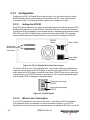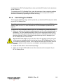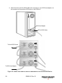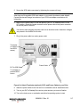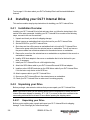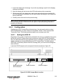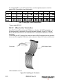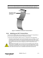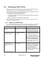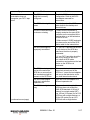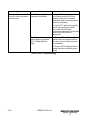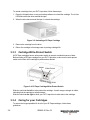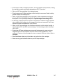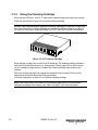
1
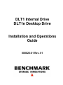
DLT1 Internal Drive
DLT1e Desktop Drive
Installation and Operations
Guide
000826-01 Rev. 01
© 1999-2000 Benchmark Storage Innovations Corporation. All rights reserved.
DLTtape and DLT are trademarks of Quantum Corporation.
Version History
Version
Date
Revised Section
01
2000-10-06
Initial Release
Details
Table of Contents
Chapter 1 Introduction.................................................................................................................1-1
1.1 Chapter Overview ................................................................................................................... 1-1
1.2 DLT1 Drive Overview .............................................................................................................. 1-1
1.2.1 Fast Data Transfer........................................................................................................... 1-1
1.2.2 High Capacity................................................................................................................... 1-2
1.2.3 Data Compaction............................................................................................................. 1-2
1.2.4 Durable Media.................................................................................................................. 1-2
1.2.5 Compatibility .................................................................................................................... 1-2
1.2.6 Firmware Update Capability ............................................................................................ 1-2
1.2.7 Embedded Diagnostics.................................................................................................... 1-2
1.3 Scope of This Guide ............................................................................................................... 1-2
Chapter 2 Installing Your DLT1 Tape Drive............................................................................2-1
2.1 Chapter Overview ................................................................................................................... 2-1
2.2 Preparation.............................................................................................................................. 2-1
2.2.1 SCSI Requirements ......................................................................................................... 2-1
2.2.2 Before You Start .............................................................................................................. 2-1
2.3 Installing your DLT1e Desktop Drive ...................................................................................... 2-2
2.3.1 Installation Overview........................................................................................................ 2-2
2.3.2 Unpacking your Drive and Selecting a Location ............................................................. 2-2
2.3.2.1 Unpacking your Drive ............................................................................................... 2-2
2.3.2.2 Selecting a Location for your Drive .......................................................................... 2-3
2.3.3 Configuration.................................................................................................................... 2-4
2.3.3.1 Setting the SCSI ID .................................................................................................. 2-4
2.3.3.2 When to Use Termination ........................................................................................ 2-4
2.3.4 Connecting the Cables .................................................................................................... 2-5
2.4 Installing your DLT1 Internal Drive ......................................................................................... 2-8
2.4.1 Installation Overview........................................................................................................ 2-8
2.4.2 Unpacking your Drive ...................................................................................................... 2-8
2.4.2.1 Unpacking your Drive ............................................................................................... 2-8
2.4.3 Configuration.................................................................................................................... 2-9
2.4.3.1 Setting the SCSI ID .................................................................................................. 2-9
2.4.3.2 When to Use Termination ...................................................................................... 2-10
000826-01 Rev. 01
i
2.4.4 Installing your DLT1 Internal Drive ................................................................................ 2-11
2.5 Testing your DLT1 Drive ....................................................................................................... 2-16
2.5.1 What to do if POST Fails ............................................................................................... 2-16
Chapter 3 Using Your DLT1 Tape Drive ..................................................................................3-1
3.1 Chapter Overview ................................................................................................................... 3-1
3.2 Front Panel Controls and Indicators....................................................................................... 3-2
3.2.1 Key to Indicators .............................................................................................................. 3-2
3.2.1.1 Indicator Activity During Power-On Self-Test (POST)............................................. 3-2
3.2.1.2 Indicator Activity During Drive Operation................................................................. 3-3
3.3 Using Cartridges ..................................................................................................................... 3-5
3.3.1 Loading a Cartridge ......................................................................................................... 3-5
3.3.2 Unloading a Cartridge...................................................................................................... 3-5
3.3.3 Cartridge Write-Protect Switch........................................................................................ 3-6
3.3.4 Caring for your Cartridges ............................................................................................... 3-6
3.3.5 Using the Cleaning Cartridge .......................................................................................... 3-8
Chapter 4 Updating Your Drive Firmware ..............................................................................4-1
4.1 Chapter Overview ................................................................................................................... 4-1
4.2 Firmware Update Overview .................................................................................................... 4-1
4.3 Creating a Code Update Cartridge ......................................................................................... 4-2
4.3.1 UN*X Systems................................................................................................................. 4-2
4.4 Updating the Firmware............................................................................................................ 4-2
4.4.1 Code Upgrade Troubleshooting ...................................................................................... 4-3
ii
000826-01 Rev. 01
List of Tables
Table 1: Setting the SCSI ID Jumper Block .................................................................................... 2-10
Table 2: POST Troubleshooting ...................................................................................................... 2-18
Table 3: Drive Status and Indicator Activity....................................................................................... 3-3
Table 4: Indicator Activity................................................................................................................... 3-4
Table 5: Code Upgrade Troubleshooting .......................................................................................... 4-3
List of Figures
Figure 2-1: DLT1e Desktop Drive Rear Panel Layout ...................................................................... 2-4
Figure 2-2: SCSI ID Switch................................................................................................................ 2-4
Figure 2-3: Attach SCSI Cable to Server or Workstation or to Previous SCSI Device .................... 2-6
Figure 2-4: Attach Terminator (optional), SCSI, and Power Cables to your Drive........................... 2-7
Figure 2-5: SCSI ID Jumper Block Location ..................................................................................... 2-9
Figure 2-6: Installing the Terminator................................................................................................ 2-10
Figure 2-7: SCSI Ribbon Cable with Terminator Built-in................................................................. 2-11
Figure 2-8: Remove Server/Workstation Cover .............................................................................. 2-12
Figure 2-9: Install Drive in an Open Drive Bay ................................................................................ 2-13
Figure 2-10: Attach SCSI and Power Cables to your DLT1 Internal Drive ..................................... 2-14
Figure 2-11: Secure DLT1 Internal Drive in Installation Bay (Side Mounting Screws Shown) ...... 2-15
Figure 3-1: DLT1 Tape Drive Front Panel......................................................................................... 3-2
Figure 3-2: Loading a DLTtape Cartridge.......................................................................................... 3-5
Figure 3-3: Unloading a DLTtape Cartridge ...................................................................................... 3-6
Figure 3-4: DLTtape Cartridge Write-Protect Switch........................................................................ 3-6
Figure 3-5: DLT Cleaning Cartridge .................................................................................................. 3-8
000826-01 Rev. 01
iii
iv
000826-01 Rev. 01
Chapter 1
Introduction
1.1
Chapter Overview
This chapter introduces your DLT1 Internal Drive, DLT1e Desktop Drive, and this Installation
and Operations Guide.
1.2
DLT1 Drive Overview
Your DLT1 tape drive is a value-priced, high-performance, high-capacity streaming cartridge
tape drive designed for use on entry to mid-range computing platforms. With a combination
of data compression and compaction, your DLT1 tape drive offers a formatted, native
cartridge capacity of 40 GB (80 GB assuming a 2:1 compression ratio) and a sustained user
data transfer rate of 3 MB/s (up to 6 MB/s with 2:1 compression). The capacity you realize in
practice depends on the data set, which affects the actual compression ratio.
Your DLT1 tape drive is built on a 5-¼ inch, full-height form-factor, using a ½-inch tape. Its
design includes a dual-channel read/write head, Lempel-Ziv (DLZ) high-efficiency data
compression, and tape-mark directory to achieve the fastest data throughput and data
access times.
1.2.1
Fast Data Transfer
Whether you use your DLT1 tape drive for unattended backups or archiving, the data
transfer rate your drive achieves is higher than many competing products. Your DLT1 tape
drive’s native (uncompressed) data transfer rate is 3.0 MB/s. With 2:1 data compression, the
data transfer rate increases to as much as 6.0 MB/s.
000826-01 Rev. 01
1-1
1.2.2
High Capacity
Your DLT1 tape drive uses of DLTtape™ IV cartridges, which offer 40 GB of native storage
or up to 80 GB of compressed data using Benchmark Storage Innovations’ enhanced
format.
The data set determines the actual data compression rate, which may vary from 2:1.
1.2.3
Data Compaction
Your DLT1 tape drive includes a data compaction feature that helps it store data efficiently.
A read/write buffer of up to 2 MB provides working space for the compaction feature,
allowing you to get the most of the available tape space.
1.2.4
Durable Media
The tape media is designed to endure 1,000,000 passes and has a shelf life of 30 years,
providing superior media durability and data reliability.
1.2.5
Compatibility
Your DLT1 tape drive is read-compatible with DLT4000 using DLTtape IV cartridges.
For current information on operating system, application, and driver compatibility, visit:
www.4benchmark.com/drivers
1.2.6
Firmware Update Capability
Your DLT1 tape drive includes Flash EEPROM technology that makes on-site firmware
(microcode) updates from tape or SCSI bus fast and easy.
1.2.7
Embedded Diagnostics
Your DLT1 tape drive has embedded diagnostic software that indicates diagnostic results
and drive operating status and even tells you when head cleaning is needed. The drive also
has embedded error logging to help you diagnose any problems.
1.3
Scope of This Guide
This Installation and Operations Guide is intended to provide all the information you need to
install and use your DLT1 Internal Drive or DLT1e Desktop Drive.
1-2
000826-01 Rev. 01
Chapter 2
Installing Your
DLT1 Tape Drive
2.1
Chapter Overview
This chapter explains how to configure and install your DLT1e Desktop Drive or DLT1
Internal Drive. Configuration and installation are not difficult and require only that you follow
the steps and instructions presented in this chapter.
2.2
Preparation
This helps you prepare to install your DLT1e Desktop Drive or DLT1 Internal Drive.
2.2.1
SCSI Requirements
Your DLT1 tape drive (desktop and internal) requires a wide, SCSI-2, Low-Voltage
Differential (LVD) or Single-Ended (SE) SCSI bus. Make sure your SCSI host adapter or
controller supports these standards. If you connect your DLT1 tape drive to an SE SCSI
bus, the drive’s performance is limited to the maximum data transfer speed of the SE bus.
Your DLT1 tape drive is not compatible with a standard differential or High-Voltage
Differential (HVD) SCSI bus.
2.2.2
Before You Start
Installing your DLT1e Desktop Drive requires no special tools. You will need a ballpoint pen
to change the SCSI ID switch on the rear panel of the drive. Installing your DLT1 Internal
Drive requires only the usual tools needed to install an internal drive in the computer you
have chosen to house the DLT1 tape drive.
000826-01 Rev. 01
2-1
If you are installing a DLT1e Desktop Drive, refer to page 2-2 for instructions. If you are
installing a DLT1 Internal Drive, refer to page 2-8 for instructions.
2.3
Installing your DLT1e Desktop Drive
This section contains step-by-step instructions for installing your DLT1e Desktop Drive.
2.3.1
Installation Overview
Installing your DLT1e Desktop Drive is fast and easy when you follow the instructions in this
section in the order presented. Installing your DLT1e Desktop Drive consists of the following
steps, covered in the next few sections:
1. Unpack and check your drive for shipping damage.
2. Select a location near the server or workstation that is to be the host for your DLT1e
Desktop Drive.
3. Set the SCSI ID for your DLT1e Desktop Drive.
4. Shut down and turn off the server or workstation that is to host your DLT1e Desktop
Drive. Remove the power cable from the selected server or workstation. Turn off and
remove the power cables from all devices attached to the selected server or workstation.
5. Install a SCSI host adapter in the server or workstation that is to be the host for your
drive, if necessary.
6. Attach the SCSI cable to your DLT1e Desktop Drive and SCSI host adapter.
7. Install the terminator on your DLT1e Desktop Drive if it is the last or only device on the
SCSI bus.
8. Attach the power cable to your DLT1e Desktop Drive and plug in the power cable to the
nearest power outlet.
9. Check your DLT1e Desktop Drive to make sure it is working properly.
2.3.2
Unpacking your Drive and Selecting a Location
Before you begin, clear a desk or table so that you can unpack your DLT1e Desktop Drive.
You also need to select a location near the server or workstation that is to host your drive.
Note: If the room in which you are working differs from the temperature at which your DLT1e
Desktop Drive was shipped or stored by 30° F (15° C) or more, let the drive acclimate to the
surrounding environment for at least 12 hours before opening the shipping carton.
2.3.2.1
Unpacking your Drive
Before you do anything else, unpack and inspect your DLT1e Desktop Drive for shipping
damage. To do a thorough job, follow these steps:
1. Inspect the shipping box for damage. If you notice any damage, report it to the shipping
company immediately.
2-2
000826-01 Rev. 01
2. Open the shipping box and remove the accessories package. Open the accessories
package so that the accessories are handy during installation.
3. With the drive still in the shipping box, reach under and around the drive, carefully lift it
out of the shipping box, and place it on the work surface, top facing up. Do not stand the
drive on either end.
4. Carefully remove the remove the drive from the protective bag.
Note: Save the packing materials in case you need to move or ship your drive in the future.
You must ship your DLT1e Desktop Drive in the original or equivalent packing materials to
preserve your warranty.
2.3.2.2
Selecting a Location for your Drive
Select a location for your DLT1e Desktop Drive that is flat, sturdy, level, and close to the
host server or workstation. A desk or table top is most suitable. Regardless of the location
you choose for your DLT1e Desktop Drive, make sure the environment is free from dust and
excessive humidity. See the DLT1 Product Specification manual for acceptable operating
humidity limits.
Be sure to follow these additional guidelines when selecting a location for your DLT1e
Desktop Drive:
•
Allow at least 6 inches (15.2 cm) behind the drive for proper cooling.
•
Avoid locations near printers or photo copy machines, both of which produce paper fiber
and other types of dust and airborne contaminants.
•
Do not place your drive on the floor.
•
Avoid locations near generators, electric motors, audio speakers, or other sources of
magnetic fields. Magnetic fields can adversely affect your drive and media.
000826-01 Rev. 01
2-3
2.3.3
Configuration
Configuring your DLT1e Desktop Drive is fast and easy. You only need to select a unique
SCSI ID and decide if your drive needs to be terminated. The DLT1 drive cannot provide
Termination Power. The following sections explain how to configure your drive.
2.3.3.1
Setting the SCSI ID
Each SCSI device attached to the server or workstation that is to be the host for your DLT1e
Desktop Drive must have a unique SCSI ID. Check the SCSI IDs on all other SCSI devices,
including the SCSI host adapter, on the selected server or workstation and select an unused
SCSI ID for your DLT1e Desktop Drive. If the drive’s factory default SCSI ID is not being
used by another device on the same SCSI bus, you do not need to change the SCSI ID.
SCSI ID
Switch
Power Switch
68-pin highdensity SCSI
connectors
Power Cable
Connector
Figure 2-1: DLT1e Desktop Drive Rear Panel Layout
To set the SCSI ID on your DLT1e Desktop Drive, use a small screwdriver or ballpoint pen
to press the button above the SCSI ID display to select the next higher SCSI ID. Press the
button below the SCSI ID display to select the next lower SCSI ID. Each time you press one
of these buttons, the SCSI ID increases or decreases by one. Press the appropriate button
until the desired SCSI ID appears on the switch display.
Press here to increase
SCSI ID
Press here to decrease
SCSI ID
Figure 2-2: SCSI ID Switch
2.3.3.2
When to Use Termination
If your DLT1e Desktop Drive is the only SCSI device – other than the SCSI host adapter –
on the selected server or workstation, it must be terminated. Likewise, if your DLT1e
Desktop Drive is the last device on the selected server or workstation’s SCSI bus, it must be
2-4
000826-01 Rev. 01
terminated. If your DLT1e Desktop Drive is at the end of the SCSI cable, it is the last device
on the SCSI bus.
To terminate your DLT1e Desktop Drive, locate the terminator in the accessories package
and press it firmly into either of the two SCSI connectors on the rear panel of the drive.
Secure the terminator by tightening the screws until snug.
2.3.4
Connecting the Cables
This is the final installation stage, which requires that you attach the SCSI and power cables
to your DLT1e Desktop Drive.
Note: If the selected server or workstation does not already have an installed SCSI-2 host
adapter, install one now. For more information on SCSI host adapter requirements, see
page 2-1.
To connect the SCSI and power cables to your DLT1e Desktop Drive, follow these steps:
1. Before you continue, shut down the operating system and turn off the selected server or
workstation. Turn off all attached accessory devices, such as printers and other SCSI
devices. Remove the power cable from the host server or workstation and all attached
accessory devices. Failure to follow these instructions may result in damage to your
DLT1e Desktop Drive or other devices.
Do not move on to step 2 until you have shut down the operating system and turned
off the server or workstation that is to be the host for your DLT1e Desktop Drive. Turn
off all attached accessory devices, such as printers and other SCSI devices. Remove
the power cables from the host server or workstation and all attached accessory
devices.
2. Locate the SCSI cable in the accessories package.
3. Attach one end of the SCSI cable to one of the connectors on the rear panel of your
DLT1e Desktop Drive.
000826-01 Rev. 01
2-5
4. Attach the other end of the SCSI cable to the connector on your SCSI host adapter or to
the connector on the previous SCSI device on the SCSI bus.
SCSI Host Adapter
DLT1e SCSI Cable
To Next SCSI Device
To SCSI Host Adapter
Figure 2-3: Attach SCSI Cable to Server or Workstation or to Previous SCSI Device
2-6
000826-01 Rev. 01
5. Secure the SCSI cable connectors by tightening the screws until snug.
Note: If the supplied SCSI cable does not fit the connector on your SCSI host adapter, you
either have an incompatible SCSI host adapter or you need to purchase a cable adapter.
Contact Benchmark Storage Innovations or your SCSI host adapter manufacturer for
information.
6. Make sure the power switch on the rear panel of your DLT1e Desktop Drive is in the
OFF position. Attach the female connector on the power cable to the power connector
on the rear panel of the drive.
Use caution when plugging the power cord into an electrical outlet. Hazardous voltages
are present in the sockets of the outlet.
7. Plug in the power cable to a nearby power outlet.
Terminator
(or cable to
next SCSI
device)
Power Cable
DLT1e SCSI Cable
To computer or
previous SCSI
device
Figure 2-4: Attach Terminator (optional), SCSI, and Power Cables to your Drive
8. Attach the power cables to the host server or workstation and all attached devices.
9. Turn on your DLT1e Desktop Drive and any other devices you turned off earlier.
10. Turn on the host server or workstation and allow its operating system to start.
000826-01 Rev. 01
2-7
Turn to page 2-16 to learn about your DLT1e Desktop Drive’s self-test and initialization
features.
2.4
Installing your DLT1 Internal Drive
This section contains step-by-step instructions for installing your DLT1 Internal Drive.
2.4.1
Installation Overview
Installing your DLT1 Internal Drive is fast and easy when you follow the instructions in this
section in the order presented. Installing your DLT1 Internal Drive consists of the following
steps, covered in the next few sections:
1. Unpack and check your drive for shipping damage.
2. Select a server or workstation that is to be the host for your DLT1 Internal Drive.
3. Set the SCSI ID for your DLT1 Internal Drive.
4. Shut down and turn off the server or workstation that is to host for DLT1 Internal Drive.
Remove the power cable from the selected server or workstation. Turn off and remove
the power cables from all devices attached to the selected server or workstation.
5. Remove the cover from the selected server or workstation as explained in the server’s or
workstation’s manuals.
6. Install a SCSI host adapter in the server or workstation that is to be the host for your
drive, if necessary.
7. Install your DLT1 Internal Drive in a full-height drive bay.
8. Attach the SCSI ribbon cable to your DLT1 Internal Drive and SCSI host adapter.
9. Install an active LVD/SE terminator on the SCSI ribbon cable if your DLT1 Internal Drive
if it is the last or only device on the SCSI bus.
10. Attach a power cable to your DLT1 Internal Drive.
11. Secure your DLT1 Internal Drive in the selected server or workstation.
12. Check your DLT1 Internal Drive to make sure it is working properly.
2.4.2
Unpacking your Drive
Before you begin, clear a desk or table so that you can unpack your DLT1 Internal Drive.
Note: If the room in which you are working differs from the temperature in which your DLT1
Internal Drive was shipped or stored by 15° C (30° F) or more, let the drive acclimate to the
surrounding environment for at least 12 hours before opening the shipping carton.
2.4.2.1
Unpacking your Drive
Before you do anything else, unpack and inspect your DLT1 Internal Drive for shipping
damage. To do a thorough job, follow these steps:
2-8
000826-01 Rev. 01
1. Inspect the shipping box for damage. If you notice any damage, report it to the shipping
company immediately.
2. Open the shipping box and remove the SCSI cable and any other accessories.
3. With the drive still in the shipping box, reach under and around the drive, carefully lift it
out of the shipping box, and place it on the work surface, top facing up. Do not stand the
drive on either end.
4. Carefully remove the drive from the protective bag.
Note: Save the packing materials in case you need to move or ship your drive in the future.
You must ship your DLT1 Internal Drive in the original or equivalent packing materials to
preserve your warranty.
2.4.3
Configuration
Configuring your DLT1 Internal Drive is fast and easy. You only need to select a unique
SCSI ID and decide if your drive needs to be terminated. The DLT1 drive cannot provide
Termination Power. The following sections explain how to configure your drive.
2.4.3.1
Setting the SCSI ID
Regardless of the number of SCSI devices attached to the server or workstation that is to be
the host for your DLT1 Internal Drive, each must have a unique SCSI ID. Check the SCSI
IDs on all other SCSI devices on the selected server or workstation, including the SCSI host
adapter, and select an unused SCSI ID for your DLT1 Internal Drive. The factory default
SCSI ID is 5. If the factory default SCSI ID is not being used, you do not need to change the
drive’s SCSI ID.
Locate the SCSI ID jumpers on the rear panel of the drive as shown in Figure 2-5.
68-pin high-density
SCSI Connector
Power Connector
SCSI ID Jumpers
Figure 2-5: SCSI ID Jumper Block Location
000826-01 Rev. 01
2-9
To set the SCSI ID on your DLT1 Internal Drive, use the supplied jumpers to select the
desired SCSI ID as shown in the following table:
SCSI ID
0
1
2
3
4
5*
6
7
8
9
10
11
12
13
14
15
Jumper
Block
SCSI ID
Jumper
Block
Table 1: Setting the SCSI ID Jumper Block
* Factory default SCSI ID
2.4.3.2
When to Use Termination
If your DLT1 Internal Drive is the only SCSI device – other than the SCSI host adapter – on
the selected server or workstation, it must be terminated. Likewise, if your DLT1 Internal
Drive is the last SCSI device on the selected server or workstation’s SCSI bus, it must be
terminated.
To terminate your DLT1 Internal Drive, insert an active LVD/SE terminator into the connector
on one end of the supplied SCSI ribbon cable as shown in Figure 2-6. Continue with the rest
Terminator
SCSI Ribbon Cable
of the installation as usual.
Figure 2-6: Installing the Terminator
2-10
000826-01 Rev. 01
Note: If the SCSI cable that came with your SCSI host adapter already has a terminator built
into it, do not use another terminator. An example of such a cable is shown in Figure 2-7.
SCSI Ribbon Cable
Supplied with SCSI
Host Adapter
Terminator
Figure 2-7: SCSI Ribbon Cable with Terminator Built-in
2.4.4
Installing your DLT1 Internal Drive
This is the final installation stage, which requires that you install your DLT1 Internal Drive in
the host server or workstation and attach the SCSI and power cables.
To connect the SCSI and power cables to your DLT1 Internal Drive, follow these steps:
1. Shut down the operating system and turn off the selected server or workstation. Turn off
all attached accessory devices, such as printers and other SCSI devices. Remove the
power cables from the host server or workstation and all attached accessories. Failure to
follow these instructions may result in damage to your DLT1 Internal Drive or other
devices.
Do not move on to step 2 until you have shut down the operating system and turned
off the server or workstation that is to be the host for your DLT1 Internal Drive. Turn off
all attached accessory devices, such as printers and other SCSI devices. Remove the
power cables from the host server or workstation and all attached accessories.
000826-01 Rev. 01
2-11
2. Remove the cover from the host server or workstation as described in the server’s or
workstation’s manuals.
Figure 2-8: Remove Server/Workstation Cover
2-12
000826-01 Rev. 01
3. Locate an available full-height, 5¼-inch drive bay and remove the front cover(s) from the
drive bay as described in the server’s or workstation’s manuals.
4. Slide your DLT1 Internal Drive into the open drive bay.
Figure 2-9: Install Drive in an Open Drive Bay
Note: Install a SCSI host adapter in the selected server or workstation now, if necessary.
For more information on SCSI host adapter requirements, see page 2-1.
000826-01 Rev. 01
2-13
Note: If your SCSI host adapter already has a ribbon cable with an open 68-pin, highdensity connector, you can use the existing cable instead of the cable supplied with your
DLT1 internal drive.
5. Locate the SCSI ribbon cable in the accessories package. Attach one end of the SCSI
ribbon cable to the SCSI connector on the rear panel of your DLT1 Internal Drive. The
SCSI connectors are keyed, preventing improper connection.
Note: If the supplied SCSI cable does not fit the connector on your SCSI host adapter, you
either have an incompatible SCSI host adapter or you need to purchase a cable adapter.
Contact Benchmark Storage Innovations or your SCSI host adapter manufacturer for
information.
Note: Refer to page 2-10 to determine if you need to use an LVD/SE terminator with the
SCSI cable.
6. Attach the other end of the SCSI ribbon cable to the SCSI host adapter, aligning the
colored stripe on the ribbon cable with pin 1 on the SCSI host adapter’s connector.
7. Locate an available power cable in the host server or workstation and attach it to the
power connector on the rear panel of your DLT1 Internal Drive. The connectors are
keyed, preventing improper connection.
SCSI Cable (Shown
with Terminator
Installed)
Power Cable
Figure 2-10: Attach SCSI and Power Cables to your DLT1 Internal Drive
2-14
000826-01 Rev. 01
8. Secure your DLT1 Internal Drive with the appropriate mounting screws, either in the
sides or bottom of the drive sled, as appropriate for the server or workstation chassis.
Figure 2-11 shows the drive without the power and SCSI cables attached for clarity.
Figure 2-11: Secure DLT1 Internal Drive in Installation Bay (Side Mounting Screws Shown)
Note: Some servers and workstations require mounting rails for internal devices. Contact
your server or workstation manufacturer for information.
9. Replace the cover on the server or workstation.
10. Attach the power cables to the server or workstation and all attached accessories.
11. Turn on the host server or workstation and allow its operating system to start.
Refer to the next section to learn about your DLT1 Internal Drive’s self-test and initialization
features.
000826-01 Rev. 01
2-15
2.5
Testing your DLT1 Drive
Every time you turn on your DLT1 tape drive, it conducts a Power-On Self-Test (POST).
This test ensures that your drive is working properly and is ready to use.
While POST is in progress, watch the front panel LEDs to see the progress and results of
the test. During POST, the following actions take place:
1. The LEDs turn on all at once and then turn off.
2. If a cartridge is loaded, the In Use (center) LED blinks during initialization and remains
illuminated after POST.
3. If there is no cartridge loaded, all LEDs turn off after POST.
POST takes several seconds to complete, after which the drive is ready to use. Turn to
Chapter 3 for operating instructions.
2.5.1
What to do if POST Fails
If all of the LEDs on the front panel blink continually instead of completing the usual POST
sequence, POST has failed. Table 2 helps you troubleshoot POST and other failures:
Symptom
Problem
Solution
None of the drive’s LEDs
illuminate.
The drive is not receiving
power.
Check the drive’s power cable. If a
desktop drive, check the power
cable connections. Plug the power
cable into a different power outlet.
All of the LEDs on the front
panel blink continually
An internal drive fault has
occurred.
1. Press and hold the Eject button
for 6 seconds to reset the drive.
2. Turn the drive off and then on
again. If the drive is a DLT1 internal
drive, shut down and turn off the
host server or workstation, then
turn it back on and allow it to boot.
3. Call technical support if POST
continues to fail.
The host server or
workstation does not
recognize your DLT1 tape
drive.
The drive’s SCSI ID might
not be unique.
Change the drive’s SCSI ID. Shut
down and turn off the host server or
workstation; turn off the desktop
drive. Change the drive’s SCSI ID.
Turn on the host server or
workstation and desktop drive.
Ensure that all devices on the SCSI
bus are SE or LVD.
(Continued on next page)
2-16
000826-01 Rev. 01
Symptom
The host server or
workstation does not
recognize your DLT1 tape
drive.
Problem
Solution
The SCSI host adapter
might be incorrectly
configured.
Check the SCSI host adapter
configuration. Refer to the SCSI
host adapter manuals for
instructions.
The SCSI cable might be
loose.
Check both ends of the SCSI
cable, both for the desktop and
internal drives.
The SCSI terminator might
be loose or missing.
1. Make sure the terminator is
properly seated on the open SCSI
connector on the rear panel of the
desktop drive or on the last device
on the SCSI bus.
2. Make sure an LVD/SE terminator
is in place on the end of the SCSI
ribbon cable for the internal drive.
The SCSI bus might be
improperly terminated.
1. If your DLT1 tape drive is the last
or only device on the SCSI bus,
make sure the drive is properly
terminated.
2. If your DLT1 tape drive is not the
last or only device on the SCSI
bus, check all SCSI cable
connections and make sure the last
device on the SCSI bus is
terminated.
The SCSI terminator might
not be at the end of the
SCSI bus or a more than
two terminators might be
present on the SCSI bus.
Make sure the terminators are
placed only at each end of the
SCSI bus – one at the host adapter
and one on the last device on the
bus, both internal and external.
The SCSI host adapter
might be in a defective
expansion slot.
Move the SCSI host adapter to a
different expansion slot.
The SCSI bus might be too
long.
Make sure the total length of the
SCSI bus does not exceed the
ANSI SCSI standard of 19 feet (6
meters) for a single-ended (SE)
bus, 40 feet (12 meters) for an LVD
SCSI bus with multiple devices, or
82 feet (25 meters) for an LVD
SCSI bus with a single device.
(continued on next page)
000826-01 Rev. 01
2-17
Symptom
There are fatal or non-fatal
errors for which you cannot
find the cause.
Problem
The SCSI bus might be
improperly terminated.
Solution
1. If your DLT1 tape drive is the last
or only device on the SCSI bus,
make sure the drive is properly
terminated. Make sure only the last
device is terminated.
2. If your DLT1 tape drive is not the
last or only device on the SCSI
bus, check all SCSI cable
connections and make sure the last
device on the SCSI bus is
terminated.
The AC power source may
not be properly grounded
(DLT1e Desktop Drive
only).
1. Plug the DLT1e Desktop Drive’s
power cable into a power outlet on
the same circuit as the host server
or workstation.
2. Plug the DLT1e Desktop Drive’s
power cable into a different power
outlet.
Table 2: POST Troubleshooting
2-18
000826-01 Rev. 01
Chapter 3
Using Your
DLT1 Tape Drive
3.1
Chapter Overview
This chapter explains how to use your DLT1 tape drive. It describes the front panel LEDs
and controls, how to load and eject DLTtape cartridges, how to use and care for DLTtape
cartridges, and how to use the cleaning cartridge.
Note: For current information on operating system, application, and driver compatibility, visit:
www.4benchmark.com/drivers
000826-01 Rev. 01
3-1
3.2
Front Panel Controls and Indicators
This section explains how to use the front-panel controls and indicators.
Power Indicator
(Desktop Drive Only)
Write Protected LED
In Use LED
Alert LED
Unload Button
Cartridge Door
Figure 3-1: DLT1 Tape Drive Front Panel
3.2.1
Key to Indicators
This section describes what each front panel indicator means and the circumstances under
which one or more indicators are illuminated or blinking.
3.2.1.1
Indicator Activity During Power-On Self-Test (POST)
Every time you turn on your DLT1 tape drive, it conducts a Power-On Self-Test (POST).
This test ensures that your drive is working properly and is ready to use.
While POST is in progress, watch the front panel LEDs to see the progress and results of
the test. During POST, the following actions take place:
1. The LEDs turn on all at once and then turn off.
2. If a cartridge is loaded, the In Use LED blinks during initialization.
3. If there is no cartridge loaded, all LEDs turn off after POST.
POST takes several seconds to complete, after which the drive is ready to use.
3-2
000826-01 Rev. 01
3.2.1.2
Indicator Activity During Drive Operation
When your DLT1 tape drive is in use, a variety of indicator LEDs can blink or be illuminated.
Table 3 describes the circumstances under which one or more indicators are illuminated or
blinking immediately after POST. Table 4 describes what each front panel indicator means.
Drive Status
Indicator Activity
No cartridge in drive
The In Use indicator is off.
A cartridge is in the drive
While the drive loads the cartridge, the In Use indicator blinks.
When the In Use indicator is steadily illuminated, the drive has
loaded the cartridge. The cartridge is ready to use.
The drive detected an error
condition
The Write-Protected LED blinks. Press and hold the Unload
button for 6 seconds, then press the Unload button again to reset
the drive and unload the cartridge. The drive runs a POST. See
section 3.2.1.1 above for POST information.
Table 3: Drive Status and Indicator Activity
000826-01 Rev. 01
3-3
Indicator
Write Protected
In Use
Alert
State
Operating Condition
On
The DLTtape cartidge is write-protected.
Off
The DLTtape cartidge is write-enabled.
Blinking
Tape is in motion.
On
The DLTtape cartridge is loaded and ready to
use.
Off
No cartridge is loaded.
On
1. 250 hours of tape motion have occurred since
the last cleaning.
2. A calibration failure or hard read/write error
occurred.
Remains On after
you unload the
cleaning tape.
After cleaning, this
indicator is
illuminated again
when you load a
DLTtape cartridge.
Off
No cleaning took place.
The DLTtape cartridge is causing problems. Try
a different cartridge. If this condition persists
with other cartridges, contact Technical Support.
1. Cleaning is complete or not needed.
2. Resetting the drive cleared the problem.
Press and hold the Unload button for six
seconds to reset the drive.
All three LEDs
On
POST is starting.
Blinking
A POST error has occurred. See Table 2 on
page 2-16 for more information.
Table 4: Indicator Activity
3-4
000826-01 Rev. 01
3.3
Using Cartridges
Your DLT1 tape drive uses only DLTtape IV cartridges. Your DLT1 tape drive can read – but
not write – DLTtape IV cartridges that use the DLT4000 format.
Note: Your DLT1 tape drive automatically unloads any other cartridge types and any
cartridges whose format it cannot read. Make sure all cartridges that you want to use for
writing are either unformatted or have been formatted with your DLT1 tape drive before
loading them. If you want to reuse cartridges that have been formatted with another
manufacturer’s drive, use a magnetic bulk eraser to prepare the cartridges for use with your
DLT1 tape drive.
3.3.1
Loading a Cartridge
To load a cartridge into your DLT1 tape drive:
After the drive completes POST, insert the DLTtape cartridge into the cartridge slot, oriented
as shown below, and push the cartridge gently into the drive until it stops.
Figure 3-2: Loading a DLTtape Cartridge
The In Use LED blinks while the drive loads the cartridge. When the cartridge is ready to
use, the In Use LED is steadily illuminated.
Note: When you insert a new, unformatted cartridge into your DLT1 tape drive, the loading
sequence takes longer because the drive is writing reference tracks on the tape.
3.3.2
Unloading a Cartridge
Caution: Remove the cartridge from your DLT1 tape drive before turning off the desktop
drive or the host server or workstation for an internal drive. Leaving a cartridge in the drive
when power is off can result in cartridge and drive damage. When you remove the
cartridge from the drive, return the cartridge to its storage case to prolong cartridge life.
000826-01 Rev. 01
3-5
To unload a cartridge from your DLT1 tape drive, follow these steps:
1. Press the Unload button or use your backup software to unload the cartridge. The In Use
LED blinks while the drive rewinds the tape.
2. When the drive has rewound the tape, it unloads the cartridge.
Figure 3-3: Unloading a DLTtape Cartridge
3. Remove the cartridge from the drive.
4. Return the cartridge to its storage case to prolong cartridge life.
3.3.3
Cartridge Write-Protect Switch
All DLTtape cartridges have a write-protect switch to prevent accidental erasure of data.
Before loading a DLTtape cartridge into your DLT1 tape drive, make sure the write-protect
switch on the front of the cartridge is positioned as desired.
Indicat
Write-Protect
Write
Write
Figure 3-4: DLTtape Cartridge Write-Protect Switch
Slide the switch to the left to write-protect the cartridge. A small orange rectangle is visible,
indicating that the cartridge is write-protected.
Slide the switch to the right to allow your DLT1 tape drive to write data to the cartridge.
3.3.4
Caring for your Cartridges
To ensure the longest possible life for all of your DLTtape cartridges, follow these
guidelines:
3-6
000826-01 Rev. 01
•
Do not drop or strike a cartridge. Excessive shock can displace the tape leader, making
the cartridge unusable and possibly damaging your DLT1 tape drive.
•
Store your DLTtape cartridges in their storage cases.
•
Do not expose your DLTtape cartridges to direct sunlight or sources of heat, including
portable heaters and heating ducts.
•
Store your DLTtape cartridges in an environment in which temperatures are always
between 50° F and 104° F (10° C to 40° C). The ideal storage temperature is 72° F,
± 7° F (22° C ± 4 ° C). Always store your DLTtape cartridges in their storage cases.
•
If a DLTtape cartridge has been exposed to temperatures outside the ranges specified
above, stabilize the cartridge at room temperature for the same amount of time it was
exposed to extreme temperatures, up to 24 hours.
•
Store your DLTtape cartridges in a dust-free environment in which relative humidity is
always between 20% and 80% (noncondensing). The ideal storage relative humidity is
40%, ± 20%.
•
Do not place DLTtape cartridges near sources of electromagnetic energy or strong
magnetic fields, such as computer monitors, electric motors, speakers, or X-ray
equipment. Exposure to electromagnetic energy or magnetic fields can destroy data on
cartridges.
•
Place identification labels only in the slide-in slot on the front of the cartridge.
•
Never use any type of adhesive labels on your DLTtape cartridges.
000826-01 Rev. 01
3-7
3.3.5
Using the Cleaning Cartridge
When the Alert LED is on, your DLT1 tape drive’s read/write head may need to be cleaned.
Follow the instructions on page 3-5 to load the cleaning cartridge.
Caution: Use only Benchmark-approved cleaning cartridges in your DLT1 tape drive.
Use of any other type of cleaning cartridge can damage the read/write head in your drive. If
you load any other type of cleaning cartridge, your DLT1 tape drive unloads it immediately.
Figure 3-5: DLT Cleaning Cartridge
Each cleaning cartridge has a useful life of 20 cleanings. The cleaning cartridge includes a
label with 20 small boxes printed on it. Always place a check mark in a box each time you
use the cartridge to clean the drive. Replace the cleaning cartridge when all boxes are
checked.
When the cleaning cartridge has cleaned the read/write head, the Alert LED turns off to
indicate that you should remove the cleaning cartridge.
Follow the instructions on page 3-5 to unload the cleaning cartridge.
Note: If any LEDs blink or if the Alert LED is illuminated again when you insert another
cartridge immediately after cleaning, see Table 4 on page 3-4 for more information.
3-8
000826-01 Rev. 01
Chapter 4
Updating Your
Drive Firmware
4.1
Chapter Overview
This chapter explains how to update your DLT1 tape drive’s firmware (microcode) from a
DLTtape cartridge or from a file on the host server or workstation.
4.2
Firmware Update Overview
Your DLT1 tape drive can automatically update the drive’s firmware directly from a DLTtape
cartridge containing the appropriate information. Your DLT1 tape drive can also update the
drive’s firmware from the host server or workstation. See the WRITE BUFFER command in
the DLT1 SCSI Interface SCSI Reference Manual.
Caution: During the firmware update process, when the new firmware/microcode is actually
being programmed into the Flash EEPROM, a power failure – but not a Bus Reset – causes
the drive’s controller module to become unstable. During a firmware update, take
reasonable precautions to prevent a power failure.
000826-01 Rev. 01
4-1
4.3
Creating a Code Update Cartridge
To perform the code update, you need a DLTtape IV cartridge and a copy of the firmware
image. This image must be byte-written without compression onto the tape. You must copy
the firmware image to the tape instead of using a backup utility to transfer it to the tape.
4.3.1
UN*X Systems
You can use the FTP utility to transfer the binary firmware image file onto the UN*X system.
Be sure to specify “type image” before performing the get or put operation. Doing so
prevents extra characters from being added to the image file, which would make the image
file invalid. The image file must be exactly 1286*512 Bytes in size. The tape must also be
uncompressed.
4.4
Updating the Firmware
To update your DLT1 tape drive’s firmware, follow the steps in this section.
Caution: Never turn off your DLT1 tape drive or the host server or workstation during the
firmware update process. Doing so can damage the drive’s controller hardware.
Note: Read these instructions completely before proceeding. All timing indications are
approximate.
1. If there is a DLT tape cartridge currently in your DLT1 drive, remove it before
proceeding.
2. If possible, power cycle (turn the drive’s power off, then back on) and allow the PowerOn Self-Test (POST) to complete successfully. The drive will emit a buzzing sound as
the head drives toward its starting point (after 4 seconds). POST will complete after 13
seconds. When POST is complete and no cartridge is inserted, all LEDs will be turned
off.
3. Press and hold the Unload button on your DLT1 drive’s front panel. Continue holding
the Unload button. The LEDs will illuminate at 6 seconds. Continue pressing the Unload
button until the LEDs turn off (12 seconds). Release the Unload button.
4. Within 4 seconds, press the Unload button again. The In-Use and Write Protect LEDs
should both blink, indicating that the drive is in firmware upgrade mode.
CAUTION: While the drive is in firmware upgrade mode, DO NOT TURN OFF YOUR DLT1
TAPE DRIVE, or the host server/workstation (if connected), until the firmware upgrade
process is complete. Doing so can damage the drive’s controller hardware.
5. Insert the Firmware Upgrade Tape into the drive. The drive then begins the process of
reading the image file from the cartridge. The In-Use and Write Protect LEDs flash
together during the upgrade process, which typically takes two or three minutes. If the
firmware upgrade process completes successfully, the drive automatically ejects the
Firmware Upgrade Tape.
4-2
000826-01 Rev. 01
6. Power cycle the tape drive. Your DLT1 drive is now ready to use with the new firmware.
Note: Please observe the following conditions:
•
You may need to restart your computer for it to recognize the tape drive.
•
If the drive does not eject the Firmware Upgrade Tape, the firmware upgrade failed. This
may be because the cartridge was not a valid Firmware Upgrade Tape. If so, no damage
has occurred. Obtain a valid Firmware Upgrade Tape and repeat the process.
•
If the Unload button is held for six seconds (LEDs on) and released before 12 seconds
(LEDs off). The drive will execute a Front Panel Reset, Run POST and then become InUse.
•
If the Unload button is held for 12 seconds and then released (not pressed within 4
seconds) the drive will revert to the In-Use mode.
4.4.1
Code Upgrade Troubleshooting
If the code upgrade failed, the drive does not unload the Code Upgrade cartridge at the end
of the process. Refer to Table 5 for troubleshooting information.
Problem
Indications/Solution
1. The cartridge is not a valid Code
Upgrade cartridge.
Indications: The drive does not attempt
to update the code. The In Use and Write
Protected LEDs do not blink. The drive
resets and leaves the cartridge loaded to
indicate that the code update did not
succeed. No damage to the drive or
cartridge results.
2. The cartridge does not contain a valid
code upgrade image file.
Solution: Make a valid Code Upgrade
cartridge to solve this problem.
The cartridge contains a valid code
upgrade image file, but the flash
EEPROM programming process fails.
The drive’s controller hardware is
probably damaged and must be replaced.
The drive resets and runs POST, which
fails if the flash EEPROM does not
contain a valid code image. If this occurs,
you must repair the drive before using it
again. Call Technical Support for repair
service.
Table 5: Code Upgrade Troubleshooting
000826-01 Rev. 01
4-3