1
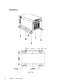
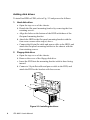
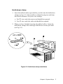
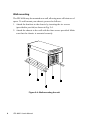
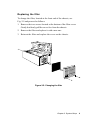
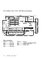
IPC-6806
6-slot Node IPC Chassis
Copyright Notice
This document is copyrighted, January 1997, by Advantech Co., Ltd.
All rights are reserved. Advantech Co., Ltd. reserves the right to make
improvements to the products described in this manual at any time
without notice.
No part of this manual may be reproduced, copied, translated, or
transmitted in any form or by any means without the prior written
permission of Advantech Co., Ltd. Information provided in this manual
is intended to be accurate and reliable. However, Advantech Co., Ltd.
assumes no responsibility for its use, nor for any infringements of the
rights of third parties which may result from its use.
Acknowledgments
IPC-6806, PCA-6106, and PCA-6106P3 are trademarks of Advantech
Co., Ltd.
Note
The information in this document is provided for reference only.
Advantech does not assume any liability arising out of the direct or
indirect use of the information or products described herein. This
manual is subject to change without notice.
Part No. 2002806030 3rd Edition
Printed in Taiwan
January 1997
Contents
Chapter 1 General Information .................................. 1
Introduction ..........................................................................
Specifications ......................................................................
Dimensions .........................................................................
Installation ...........................................................................
1
1
3
4
Chapter 2 System Setup ............................................ 5
Removing the cover ............................................................
Adding disk drives ...............................................................
Hold-down clamp ................................................................
Wall mounting ......................................................................
Replacing the filter ...............................................................
5
6
7
8
9
Appendix A Passive Backplanes ............................ 11
Appendix B Exploded Diagram............................... 13
Appendix C Safety Instructions .............................. 15
Wichtige Sicherheishinweise ............................................ 16
Chapter 1 General Information
Introduction
Specially designed for the factory floor and other harsh industrial
environments, the IPC-6806 wallmount IPC chassis is ideal for system
integrators or users who require a compact, rugged PC/AT-compatible
system. The IPC-6806 features a 6-slot passive backplane and a
150-watt power supply. The chassis is only 6.5" wide and can be easily
mounted on panels or walls with the supplied brackets.
Specifications
• Construction: Heavy-duty steel
• Disk drive capacity: One 3½" FDD and one 3½" HDD
• Indicators: LEDs for power On/Off and HDD
• Controls: Reset switch on front panel
• Cooling fan: One 49-CFM fan on front panel with air filter
• Weight: 5.6 kg (12.3 lbs)
• Dimensions (W x D x H): 166 x 170 x 393 mm (6.5" x 6.7"x 15.5")
• Paint color: Pantone 415C
Passive backplane (PCA-6106)
• Slots: 6 ISA-bus, full-size
• PC board: 4-layer PCB with ground and power planes for reduced
noise and low power-supply impedance
• Indicators: LEDs for +5 V, +12 V, -5 V and -12 V
Passive backplane (PCA-6106P3)
• Slots: 2 ISA / 3 PCI / 1 PICMG slots
• PC board: 4-layer PCB with ground and power planes for reduced
noise and low power-supply impedance
• Indicators: LEDs for +5 V, +12 V, -5 V and -12 V
Chapter 1 General Information
1
Power supply (PS-150)
• Output rating: 150 watts max.
• Input voltage:
90 ~ 132 VAC or 180 ~ 264 VAC @ 47 ~ 63 Hz, autoranging
• Output voltage: +5 V @ 15 A, -5 V @ 1 A, +12 V @ 5 A, -12 V @ 1 A
• Min load: +5 V @ 3 A, -5 V @ 0.2 A, +12 V @ 1 A, -12 V @ 0.2 A
• MTBF: 50,000 hrs. at 70% load
• Safety: UL/CSA/TÜV approved
• EMI: Meets FCC/VDE Class A
Environmental specifications
• Operating temperature: 0 ~ 50° C (32 ~ 122°F)
• Relative humidity: 10 ~ 95% @ 40° C, non-condensing
• Vibration (operating):
5 ~ 17 Hz, 0.1" double-amplitude displacement
17 ~ 500 Hz, 1.5 G acceleration peak to peak
• Shock (operating): 10 G acceleration peak (11 msec. duration)
• Safety: Meets UL/CSA/TÜV
• EMI: Meets FCC/VDE Class A
• CE compliant
2
IPC-6806
User's Manual
Rear view
Top view
Front view
Dimensions
Unit: mm
Chapter 1 General Information
3
Installation
Unit: mm
4
IPC-6806
User's Manual
Chapter 2 System Setup
The following procedures are provided to assist you in installing
drives, plug-in cards and the hold-down clamp into the IPC-6806.
Removing the cover
To remove the cover, proceed as follows:
1. Remove the two screws (one on each side) which secure the cover
to the card cage (see Fig. 2-1). Lift the lid to expose the interior of
the chassis.
Figure 2-1: Removing the cover
Chapter 2 System Setup
5
Adding disk drives
To install an HDD or FDD, refer to Fig. 2-2 and proceed as follows:
1. Hard disk drive:
a. Open the top cover of the chassis.
b. Detach the flat panel mounting bracket by removing the four
retaining screws.
c. Align the holes on the bottom of the HDD with those of the
flat-panel mounting bracket.
d. Attach the HDD to the flat-panel mounting bracket with the
four screws removed in step (a) above.
e. Connect the 40-pin flat cable and power cable to the HDD, and
attach the flat-panel mounting bracket to the chassis with the
four retaining screws.
2. Floppy disk drive:
a. Open the top cover of the chassis.
b. Remove the cover of the floppy disk drive.
c. Insert the FDD into the mounting bracket with its base facing
inward.
d. Connect a 34-pin flat cable and power cable to the FDD, and
attach the FDD to the bracket with four screws.
Figure 2-2: Installing the drives
6
IPC-6806 User's Manual
Hold-down clamp
1. Insert the rubber buffers (provided in your kit) into the hold-down
clamp (see Fig. 2-3). These buffers cushion the plug-in cards from
shock and vibration. They have two settings:
a. For XT-size cards, the narrow end should face upward.
b. For AT-size cards, the wide end should face upward.
2. When you have finished inserting the rubber buffers, fasten the
hold-down clamp to the card cage with the two screws provided
(see Fig. 2-3).
Figure 2-3: Hold-down clamp installation
Chapter 2 System Setup
7
Wall mounting
The IPC-6806 may be mounted on a wall, allowing more efficient use of
space. To wall-mount your chassis, proceed as follows:
1. Attach the brackets to the chassis by inserting the six screws
(provided in your kit) as shown in Fig. 2-4.
2. Attach the chassis to the wall with the four screws provided. Make
sure that the chassis is mounted securely.
Figure 2-4: Wall-mounting the unit
8
IPC-6806 User's Manual
Replacing the filter
To change the filter, located at the front end of the chassis, see
Fig. 2-5 and proceed as follows:
1. Remove the two screws located at the bottom of the filter cover.
Gently but firmly pull the cover free from the chassis.
2. Remove the filter and replace it with a new one.
3. Reinsert the filter and replace the cover on the chassis.
Figure 2-5: Changing the filter
Chapter 2 System Setup
9
10
IPC-6806 User's Manual
Appendix A Passive Backplanes
PCA-6106: 6-slot ISA-bus backplane
Bus termination:
Resistor ....... Signals
RP5 .............. SA7-SA0
RP4 .............. SA15-SA8
RP1 .............. SD7-SD0
RP7 .............. SD8-SD15
Resistor ....... Signals
RP2 .............. SMEMW, SMEMR, IOW, IOR
RP6 .............. SBHE, LA23-LA17
RP3 .............. LA19-LA16
IPC-6806 User's Manual
11
PCA-6106P3: 2 ISA / 3 PCI / 1PICMG-slot backplane
Bus termination:
Resistor ....... Signals
RN4 .............. SA7-SA0
RN3 .............. SA15-SA8
RN2 .............. SD7-SD0
RN6 .............. SD8-SD15
12
IPC-6806 User's Manual
Resistor ....... Signals
RP1 .............. SMEMW, SMEMR, IOW, IOR
RN5 .............. SBHE, LA23-LA17
RN1 .............. LA19-LA16
Appendix B Exploded Diagram
IPC-6806 User's Manual
13
14
IPC-6806 User's Manual
Appendix C Safety Instructions
1. Read these safety instructions carefully.
2. Keep this installation reference guide for later reference.
3. Disconnect this equipment from any AC outlet before cleaning. Do not use
liquid or spray detergents for cleaning. Use a damp cloth.
4. For pluggable equipment, the power outlet must be installed near the
equipment and must be easily accessible.
5. Keep this equipment away from humidity.
6. Put this equipment on a reliable surface during installation. Dropping it or
letting it fall could cause damage.
7. The openings on the enclosure are for air convection. Protect the equipment
from overheating. DO NOT COVER THE OPENINGS.
8. Before connecting the equipment to a power outlet, make sure the voltage of
the power source is correct.
9. Position the power cord so that people cannot step on it. Do not place
anything over the power cord.
10. All cautions and warnings on the equipment should be noted.
11. If the equipment is not used for a long time, disconnect it from the power
source to avoid damage by transient over-voltage.
12. Never pour any liquid into an opening. This could cause fire or electrical
shock.
13. Never open the equipment. For safety reasons, the equipment should be
opened only by qualified service personnel.
14. If any of the following situations arises, get the equipment checked by service
personnel:
a. The power cord or plug is damaged.
b. Liquid has penetrated into the equipment.
c. The equipment has been exposed to moisture.
d. The equipment does not work well, or you cannot get it to work according
to the installation reference guide.
e. The equipment has been dropped and damaged.
f. The equipment has obvious signs of breakage.
15. DO NOT LEAVE THIS EQUIPMENT IN AN UNCONTROLLED
ENVIRONMENT WHERE THE STORAGE TEMPERATURE IS BELOW
-20° C (-4° F) OR ABOVE 60° C (140° F). THIS MAY DAMAGE THE
EQUIPMENT.
The sound pressure level at the operator's position according to IEC
704-1:1982 is equal to or less than 70 dB(A).
DISCLAIMER: This set of instructions is given according to IEC 704-1.
Advantech disclaims all responsibility for the accuracy of any statements
contained herein.
IPC-6806 User's Manual
15
Wichtige Sicherheishinweise
1. Bitte lesen sie Sich diese Hinweise sorgfältig durch.
2. Heben Sie diese Anleitung für den späteren Gebrauch auf.
3. Vor jedem Reinigen ist das Gerät vom Stromnetz zu trennen. Verwenden Sie
Keine Flüssig-oder Aerosolreiniger. Am besten dient ein angefeuchtetes Tuch
zur Reinigung.
4. Die Netzanschlußsteckdose soll nahe dem Gerät angebracht und leicht
zugänglich sein.
5. Das Gerät ist vor Feuchtigkeit zu schützen.
6. Bei der Aufstellung des Gerätes ist auf sicheren Stand zu achten. Ein Kippen
oder Fallen könnte Verletzungen hervorrufen.
7. Die Belüftungsöffnungen dienen zur Luftzirkulation die das Gerät vor
überhitzung schützt. Sorgen Sie dafür, daß diese Öffnungen nicht abgedeckt
werden.
8. Beachten Sie beim Anschluß an das Stromnetz die Anschlußwerte.
9. Verlegen Sie die Netzanschlußleitung so, daß niemand darüber fallen kann. Es
sollte auch nichts auf der Leitung abgestellt werden.
10. Alle Hinweise und Warnungen die sich am Geräten befinden sind zu beachten.
11. Wird das Gerät über einen längeren Zeitraum nicht benutzt, sollten Sie es vom
Stromnetz trennen. Somit wird im Falle einer Überspannung eine Beschädigung vermieden.
12. Durch die Lüftungsöffnungen dürfen niemals Gegenstände oder Flüssigkeiten
in das Gerät gelangen. Dies könnte einen Brand bzw. elektrischen Schlag
auslösen.
13. Öffnen Sie niemals das Gerät. Das Gerät darf aus Gründen der elektrischen
Sicherheit nur von authorisiertem Servicepersonal geöffnet werden.
14. Wenn folgende Situationen auftreten ist das Gerät vom Stromnetz zu trennen
und von einer qualifizierten Servicestelle zu überprüfen:
a - Netzkabel oder Netzstecker sind beschädigt.
b - Flüssigkeit ist in das Gerät eingedrungen.
c - Das Gerät war Feuchtigkeit ausgesetzt.
d - Wenn das Gerät nicht der Bedienungsanleitung entsprechend funktioniert
oder Sie mit Hilfe dieser Anleitung keine Verbesserung erzielen.
e - Das Gerät ist gefallen und/oder das Gehäuse ist beschädigt.
f - Wenn das Gerät deutliche Anzeichen eines Defektes aufweist.
Der arbeitsplatzbezogene Schalldruckpegel nach DIN 45 635 Teil 1000 beträgt
70 dB(A) oder weiger.
DISCLAIMER: This set of instructions is given according to IEC 704-1.
Advantech disclaims all responsibility for the accuracy of any statements
contained herein.
16
IPC-6806 User's Manual