1
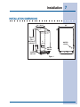
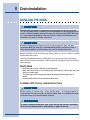
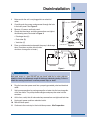
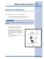
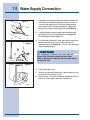
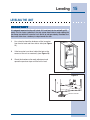
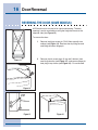
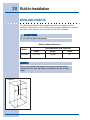
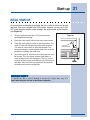
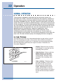
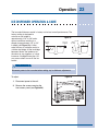
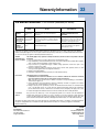
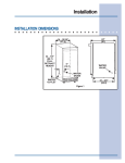
Use & Care Guide
Ice Maker
Machine à glaçons
5995421640
Dishwasher
2 Finding Information
PLEASE READ AND SAVE THIS GUIDE
Attach your sales
receipt to this
page for future
reference.
Thank you for choosing Electrolux, the new premium brand in home appliances.
This Use & Care Guide is part of our commitment to customer satisfaction and
product quality throughout the service life of your new ice maker.
We view your purchase as the beginning of a relationship. To ensure our ability to
continue serving you, please use this page to record key product information.
IMPOR
TANT
IMPORT
PLEASE READ all instructions completely before attempting to install or operate the
unit.
All ice makers require a connection to both a water supply and an electrical power
source. Improper hook-up can result in substantial property damage! Proper
installation, in accordance with the manufacturer's specifications and all local codes, is
the sole responsibility of the consumer. The manufacturer is not responsible for any
installation expenses or damages incurred due to improper installation. If you are
unsure of your ability to safely make electric power, water supply, and water drain
connections to the unit, consult licensed and insured professionals to perform all
electrical and plumbing work.
Once you have your unit installed, we suggest you keep this manual in a safe
place for future reference. Should any problems occur, refer to the
Troubleshooting section of this manual. This information will help you quickly
identify a problem and get it remedied. In the event you require assistance, please
contact the dealer where you purchased your unit.
MAKE A RECORD FOR QUICK REFERENCE
Whenever you call to request information or service, you will need to know your
model number and serial number. You can find this information on the serial plate
located on the inside wall of your unit and on the product registration card.
©2004 Electrolux Home Products, Inc.
Post Office Box 212378, Augusta, Georgia 30917, USA
All rights reserved. Printed in the USA
Finding Information
PRODUCT REGISTRATION CARD
The package containing this manual also includes your product registration
information. Warranty coverage begins at the time your Electrolux ice maker was
purchased.
NO
TE
NOTE
Registering your product with Electrolux enhances our ability to serve you. You can
register online (at the Internet address below) or by dropping your Product Registration
Card in the mail. Complete and mail the Product Registration Card as soon as possible
to validate the registration date.
Please record the purchase date of your Electrolux unit and your dealer’s name,
address and telephone number.
________________________________________________
Purchase Date
________________________________________________
Electrolux Model Number
________________________________________________
Electrolux Serial Number
________________________________________________
Dealer Name
________________________________________________
Dealer Address
________________________________________________
Dealer Telephone
Keep this manual and the sales receipt together in a safe place for further
reference.
QUESTIONS?
For toll-free telephone support in the U.S. and Canada:
1-877- 4ELECTROLUX (1-877-435-3287)
For online support and Internet product information:
www.electroluxusa.com
3
Safety
IMPORTANT SAFETY INSTRUCTIONS
Safety Precautions
Do not attempt to install or operate your unit until you have read the safety
precautions in this manual. Safety items throughout this manual are labeled with a
Danger, Warning or Caution based on the risk type.
Definitions
This is the safety alert symbol. It is used to alert you to potential personal injury
hazards. Obey all safety messages that follow this symbol to avoid possible injury
or death.
!
!
DANGER
DANGER indicates an imminently hazardous situation which, if not avoided, will result
in death or serious injury.
!
WARNING
WARNING indicates a potentially hazardous situation which, if not avoided, could
result in death or serious injury.
!
CA
UTION
CAUTION
CAUTION indicates a potentially hazardous situation which, if not avoided, may result
in minor or moderate injury, product damage, or property damage.
IMPOR
TANT
IMPORT
Indicates installation, operation or maintenance information which is important but
not hazard related.
5
6 Safety
General Precautions
!
DANGER
RISK OF CHILD ENTRAPMENT. Before you throw away your old appliance, take off the
doors and leave shelves in place so that children may not easily climb inside.
!
WARNING
• Never attempt to repair or perform maintenance on the unit until the electricity has
been disconnected.
• Altering, cutting of power cord, removal of power cord, removal of power plug, or
direct wiring can cause serious injury, fire and/or loss of property and/or life and
will void the warranty.
• Do not lift unit by door handle.
!
CA
UTION
CAUTION
• Use care when moving the unit. Some edges are sharp and may cause personal
injury. Wear gloves when moving or repositioning the unit.
• Never install the unit behind closed doors. Be sure front grille is free of
obstruction. Obstructing free air flow can cause the unit to malfunction, and may
void the warranty.
• Allow unit temperature to stabilize for 24 hours before use.
• Never use an ice pick or other sharp instrument to help speed up defrosting. These
instruments can puncture the inner lining or damage cooling unit
• Failure to clean the condenser every three months can cause the unit to
malfunction. This could void the warranty.
!
CA
UTION
CAUTION
• Using a heater to speed up defrosting can cause personal injury and damage to
the inner lining. DO NOT use any type of heater to defrost.
• Use only genuine Electrolux replacement parts. Imitation parts can reduce ice rate,
cause water to overflow from ice maker mold, damage the unit, and may void the
warranty.
Installation
7
INSTALLATION DIMENSIONS
24”
(61)
14 - 15/16”
(37.9)
34 - 1/8”
(86.7)
FULL
RETRACT
HEIGHT
5”
(12.7)
WATER
VALVE
WATER
DRAIN
WATER
OUTLET
21 - 3/4”
(55.2)
Figure 1
8 Drain Installation
INSTALLING THE DRAIN
!
CA
UTION
CAUTION
PLEASE READ all instructions completely before attempting to install or operate the
unit. All ice makers require a connection to the water supply and improper hook-up can
result in substantial property damage! All water and drain connections MUST BE made
by a licensed/qualified plumbing contractor. Failure to follow recommendations and
instructions may result in damage and/or harm.
!
CA
UTION
CAUTION
Plumbing installation must observe all state and local codes. All water and drain
connections MUST BE made by a licensed/qualified plumbing contractor. Failure to
follow recommendations and instructions may result in damage and/or harm.
Model E15IM60E can be installed using a gravity drain or can use a factory installed
or equivalent drain pump.
Follow these guidelines when installing drain lines to prevent water from flowing
back into the ice maker storage bin and/or potentially flowing onto the floor causing
water damage:
Gravity Drain
• Drain lines must have a 5/8 inch inside diameter.
• Drain lines must have a 1 inch drop per 48 inches of run (1/4 inch per foot) and
must not create traps.
• The floor drain must be large enough to accommodate drainage from all
drains.
• Insulate the bin drain line to prevent condensation.
Ice Makers With Factory Installed Drain Pump
!
CA
UTION
CAUTION
Before installing an icemaker with a factory installed pump, it is extremely important to
check and test all hose connections at the drain pump. There is a possibility that hose
connections may have loosened during shipment.
!
WARNING
To prevent accidental electrocution, make certain that the floor surfaces surrounding
the unit are dry whenever power is removed from, or applied to the unit.
Drain Installation
1
Make certain the unit is not plugged into an electrical
outlet.
2
Carefully push the power cord grommet through the hole
in the back panel. See Figure 2.
3
Remove 12 screws and back panel.
4
Check that the clamps and hose connections are tight at
the following areas illustrated in Figure 3:
9
• Discharge tube (A)
• Drain tube (B)
• Vent tube (C)
5
Place a suitable container beneath the pump’s discharge
tube. (Container must be able to hold a
minimum of one gallon of water.)
B
Figure 2
B
C
A
BACK VIEW
SIDE VIEW
UL184-2
Figure 3
!
WARNING
Back panel serves as a guard. DO NOT put your hands inside the ice maker cabinet or
attempt to touch any components except the discharge tube during testing. Failure to
follow this warning could result in serious personal injury or death.
6
Plug the ice maker power cord into a properly grounded, polarized electrical
outlet.
7
Verify pump operation by pouring one gallon of water into the ice storage bin
of the ice maker. The pump should energize and pump the water into the
container.
8
At this time, verify that all tube and clamp connections are tight and leak free.
9
Unplug unit power cord from electrical outlet.
10 Reinstall back panel.
11
Continue to the next step in the installation process, Site Preparation.
10 Drain Pump Connection
CONNECTING A DRAIN PUMP
If a gravity drain connection is not available, and you have not purchased the
E15IM60E with factory installed pump, we strongly recommend the use of the
Electrolux EIMP60 drain pump. The Electrolux EIMP60 drain pump is available
through your Dealer, or direct from Electrolux with complete installation instructions.
If a pump other than the Electrolux EIMP60 drain pump is to be used, it must meet
the following specifications:
•
It must be UL listed and have a UL listed, 120 VAC, 3-wire grounded power
cord.
•
It must have overall maximum outside dimensions of 8-3/4" wide x 5-3/4"
deep x 7-3/4" high.
•
It must have a minimum flow rate of 15 gallons per hour at 10 feet of lift.
•
It must have a sealed sump which does not allow water leakage in the case
of a power outage, restricted drain or pump failure.
•
It must have a check valve in the discharge line to prevent waste water return
to the pump.
•
It must have an overflow protection control which will shut off power to the ice
maker in the event of a pump failure.
•
It must have an operating temperature range of 50°F to 110°F (10°C to 43°C).
!
CA
UTION
CAUTION
In the event of a power outage, restricted drain or pump failure, the failure to use the
Electrolux EIMP60 drain pump or a pump with the above listed specifications, could
result in substantial water leakage and pooling with severe and costly water damage
and related consequential damages and harm.
Site Preparation
PREPARING THE SITE
IMPOR
TANT
IMPORT
It is extremely important that the unit is level. If it is not level, the ice mold will not fill
evenly. This can cause a reduction in ice rate, uneven sized cubes or water spilling into
the storage area which will cause the ice in the bin to melt pre-maturely. Remember that
floors near drains have a tendency to slope towards the drain.
1
Position the unit on a flat, level surface, capable of supporting the entire
weight of the unit. Remember that the unit will be significantly heavier once it
is fully loaded.
2
The surrounding air temperature must be at least 50°F (10°C) but must not
exceed 110°F (43°C).
3
The unit must not be located near heat-generating equipment or in direct
sunlight.
!
DANGER
ELECTROCUTION HAZARD!
Electrical Grounding Required. This appliance is equipped with a three prong
(grounding) polarized plug for your protection against possible shock hazards.
• NEVER remove the round grounding prong from the plug.
• NEVER use a two-prong grounding adapter.
• NEVER use an extension cord to connect power to the unit.
Where a two-prong wall receptacle is encountered or a longer power cord is required,
contact a qualified electrician to have it replaced in accordance with applicable
electrical codes.
4
The unit must be located to allow clearance for water, drain and electrical
connections in the rear of the ice maker.
5
Connect the unit to a grounded and polarized 115 VAC, 60 Hz, 15 A circuit
(normal household current).
6
Avoid connecting the unit to a Ground Fault Interruptor (GFI). GFIs are prone to
nuisance tripping which will cause the unit to shut down. GFIs are generally not
used on circuits which power equipment that must run unattended for long
periods of time.
7
The unit must be installed according to your local codes and ordinances.
11
12 Site Preparation
NO
TE
NOTE
The door of the unit may be mounted on either side of the cabinet (see REVERSING THE
DOOR). All units require zero clearance when installed flush with a cabinet or wall (see
Figure 4). Electrolux stainless steel models require a minimum 2-3/4 inch handle
clearance when installed against a wall or cabinet that extends beyond the front edge of
the unit (see Figure 5).
CABINET
OR WALL
DOOR
SWING
0"
CLEARANCE
NEEDED
UL124A
Figure 4
2 - 3/4”
Figure 5
EXHAUST
Figure 6
INTAKE
6
Install and connect the water supply line. See
Connecting the Water Supply for installation
requirements.
7
Position the unit to allow free air flow through the
front grille (see Figure 6).
8
Wipe out inside of unit with a damp cloth.
Water Supply Connection
13
CONNECTING THE WATER SUPPLY
When connecting the water supply, follow these guidelines:
•
Review the local plumbing codes before you install the unit.
•
The water pressure should be between 20 and 120 psi.
CA
UTION
CAUTION
!
If you are using a filter system you will need to have at least 20 psi for 3 minutes every
15 minutes.
•
Make certain a SHUT-OFF VALVE is
installed in the 1/4 inch water supply line.
•
Connect sufficient tubing to the unit to allow
the unit to be moved for cleaning and
servicing. However, make certain that the
tubing is not pinched or damaged during
installation.
•
WATER
CONNECTION
Electrolux recommends the use of copper
tubing for installation.
UL103_CO
Figure 7
14 Water Supply Connection
Figure 8
1
Locate the compression fitting and ferrule packed in the
unit. Slide the compression fitting and ferrule over the
1/4 inch water supply line. Do not use thread sealing
compound or tape. Using two wrenches, tighten the
compression fitting on the supply line (see Figure 8).
2
Carefully bend the water supply line into position and
connect the line to the solenoid valve (see Figure 9).
Avoid kinking the water supply line.
3
For recessed installations, allow extra water supply line
length to provide slack for easy removal from the
recessed area (see Figure 10). This will also safeguard
against kinking the line.
UL134
Figure 9
!
CA
UTION
CAUTION
After completing the installation, turn on the water and
recheck water and drain connection for leaks. Apply
additional tightening if needed. Do NOT use thread sealing
com-pound or tape.
Figure 10
4
Plug in the power cord.
5
Gently push the unit into position. If desired the unit may
be recessed into cabinet or wall.
6
Allow at least 1-1/2 inches clearance behind the unit for
electrical, water supply and drain connections.
15
Leveling
LEVELING THE UNIT
IMPOR
TANT
IMPORT
It is extremely important that the unit is level. If it is not level, the ice mold will not fill
evenly. This can cause a reduction in ice rate, uneven sized cubes or water spilling into
the storage area which will cause the ice in the bin to melt pre-maturely. Remember that
floors near drains have a tendency to slope towards the drain.
1
Use a level to check the levelness of the ice maker
from front to back and from side to side (see Figure
11).
2
If the ice maker is not level, adjust the feet on the
corners of the unit as necessary (see Figure 12).
3
Check the levelness after each adjustment and
repeat the previous steps until the unit is level.
CHECK
LEVEL
Figure 11
Figure 12
TURN FOOT TO ADJUST
16 Door Reversal
REVERSING THE DOOR (SOME MODELS)
All Electrolux units may be left or right hand opening. The door
opening is easily reversed by moving the hinge hard-ware to the
opposite side (see Figure 13).
To reverse the door:
Figure 13
1
Remove top hinge screw pin (7/64" Allen wrench) from
cabinet (see Figure 14). Remove door by tilting forward
and lifting off bottom hinge pin.
2
Remove plastic screw plugs (3 top and 3 bottom) from
new hinge location (see Figure 15), and remove hinge pin
hole plug in top of door (see Figure 16). Do not discard.
Figure 14
SCREW
PLUGS
Figure 15
Hole
Plug
Figure 16
17
Door Reversal
HINGE
SCREW
PIN
3
Remove top hinge (3 screws), reinstall hinge screw pin, and
remount on opposite side BOTTOM (see Figure 17).
4
Remove the two door closer inserts from the existing bottom
hinge and install as shown on the new bottom hinge (see
Figure 18).
5
Remove existing bottom hinge (3 screws) and remount on
opposite side TOP. Remove hinge screw pin.
6
With bottom of door facing up, remove pivot plate (2 screws),
flip over, and remount on opposite side of door (see Figure 19).
7
Holding door upright with top of door tilted forward, place hole of
door pivot plate on bottom hinge screw pin (see Figure 20). Be
sure that the bosses on the closers align with holes in hinge
and hinge plate.
8
Tilt top of door into position in top hinge and install top hinge
screw pin.
9
In empty hinge holes, install plastic screw plugs (3 top and 3
bottom) and door hole plug (1,door top) removed in step 2.
Figure 17
UL313
DOOR
CLOSER
INSERTS
BOSS
Figure 18
UL312
Figure 19
UL319
Figure 20
BOSS
CLRCO008
18 Door Adjustment
ADJUSTING THE DOOR
Your door is aligned at the factory before shipment. Occasional re-adjustment may
be necessary, especially if an overlay panel is installed. The following procedure
will correct for up to 1/4" alignment.
The door should never be flush with the top of the cabinet. Even when level, the top
edge of the door will be 1/8" below the top of the cabinet (see Figure 21).
To adjust :
Figure 21
1
Compare the top edge of the door (opposite the
hinges) to the top edge of the cabinet and note the
type (up or down) of adjustment needed.
2
Remove the top hinge pivot pin with a 7/64" hex
wrench (see Figure 22) and lift door off bottom
hinge pin. Be careful not to lose door closers (see
Figure 24).
3
With door upside-down, loosen but do not remove
the two hinge plate screws.
1/8”
Figure 22
Door Adjustment
4
5
If door edge opposite the hinges needs to
move up, move plate toward outside of
door. If door edge needs to move down,
move plate toward inside of door (see
Figure 23). Repeat until top edge of door is
parallel with top of cabinet and tighten
screws securely.
After adjustment is complete, remove the
door closers from the bottom hinge, clean
thoroughly and apply petroleum jelly to the
mating surfaces of the closers (see
Figure 24). Be sure that bosses on closers
align with holes in hinge and hinge plate.
Mount door and install top hinge pivot pin.
19
Figure 23
SLOTTED
MOUNTING
HOLES
NOTCH
RAISE
OUTSIDE
DOOR EDGE
LOWER
OUTSIDE
DOOR EDGE
CLRCO001a
DOOR
CLOSERS
BOSS
Figure 24
UL312
4 Finding Information
TABLE OF CONTENTS
Finding Information ........................................... 2
Please Read And Save This Guide ................... 2
Make A Record For Quick Reference ................ 2
Warranty Registration Card ............................... 3
Questions? ........................................................ 3
Table Of Contents .............................................. 4
Built-in Installation .......................................... 20
Safety ................................................................... 5
Important Safety Instructions .............................. 5
Maintenance ...................................................... 25
Special Considerations .................................... 25
Maintaining and Cleaning ................................ 25
Exterior Cleaning ............................................ 25
Stainless Steel Models ..................................... 25
Interior Cleaning .............................................. 26
Condenser Cleaning ....................................... 27
Self Cleaning ................................................... 28
Inlet Screen Cleaning ...................................... 29
Installation .......................................................... 7
Installation Dimensions ....................................... 7
Drain Installation ................................................ 8
Drain Pump Connection ................................... 10
Site Preparation ................................................. 11
Water Supply Connection ............................... 13
Leveling ............................................................. 15
Start-up .............................................................. 21
Normal Operation .............................................. 22
Ice Cube Thickness ......................................... 22
Ice Dispsenser Operation and Care ................ 23
Storage, Vacation and Moving ........................ 30
Door Reversal .................................................... 16
Troubleshooting ............................................... 31
If Service Is Required ...................................... 32
Door Adjustment ............................................... 18
Warranty Information ....................................... 33
20 Built-In Installation
INSTALLING A BUILT-IN
Your Electrolux product has been designed for either free-standing or built-in
installation. When built-in, your ice maker does not require additional air space for
top, sides or rear. However, the front grille must NOT be obstructed.
CA
UTION
CAUTION
!
Do not install unit behind closed doors.
Built-in Cabinet Dimensions
Unit Dimensions (see Figure 25)
Model
E15IM60E
Width
Height
Depth
14-15/16"
34-1/8"
24"
NO
TE
NOTE
To ease unit installation and removal, the unit must be located to allow
clearance for water, drain and electrical connections in the rear of the ice
maker.
Figure 25
W
H
D
UL118
21
Start-up
INITIAL START-UP
Once installation and leveling is complete, the unit is ready for initial start-up and
operation. Your unit is shipped in the OFF position, however, you may turn it ON/
OFF using the cycle selector switch located in the access panel above the grille
(see Figure 26).
1
Plug the appliance cord into a 115V polarized and
grounded electrical outlet.
2
Open the water supply valve in the main water source.
3
Place the cycle selector switch in the ON position. The
water fill valve will energize and fill the water reservoir.
The water fill valve shuts off after 180 seconds. The
compressor begins to operate and water flows over the
evaporator assembly (ice cube tray).
Figure 26
C
L
N
4
O
F
F
O
N
CYCLE
SELECTOR SWITCH
Upon initial start-up, water flow over the evaporator may
be uneven. This may cause uneven sized cubes or
water spilling into the ice storage bin. This is a normal
situation and will correct itself within the first 24 hours of
operation. After the initial start-up period, the water will
cascade evenly over the evaporator.
IMPOR
TANT
IMPORT
It is possible that dirt or scale will dislodge in the water line. Always throw away all ice
cubes made during the first two to three hours of operation.
C
L
N
O
F
F
O
N
22 Operation
NORMAL OPERATION
The ice maker is designed to make clear ice from most water sources on a
consistent basis. Water is constantly circulated over the evaporator assembly. As
the water freezes, gravity causes any sediment to drop into the water trough and
not become imbedded in the ice. This gives a clearer ice cube with a low mineral
content. When the ice reaches the desired thickness, it falls off the evaporator and
into the storage bin. The cycle is then repeated. When the level of ice reaches the
top of the storage bin the unit shuts off. As the ice level in the bin drops the unit will
automatically restart to keep the bin full. Your unit’s ice production rate may vary
depending on many considerations. Ambient air temperatures, water
temperatures, condenser cleanliness and ice-maker cleanliness are all
contributing factors to how quickly the unit produces ice. Certain sounds are
normal during the unit’s operation. You may hear the compressor or fan motor, the
water valve, the water circulation pump or ice dropping into the ice storage bin.
Ice Cube Thickness
Your Electrolux ice maker uses advanced technology to make ice that is crystal
clear. This technology cascades a flow of water over a chilled ice mold that is
mounted vertically so no water sits in it. Because of this ice making technology,
clear ice cubes differ significantly from regular ice cubes. Differences are
illustrated in Figure 27:
•
Dimples. Electrolux clear ice cubes
have “dimples” on one side from the
cascading water process.
•
Cube Variations. Cubes made from
different batches, or even cubes
within the same batch may have
varying dimples, thickness and/or
sizes due to the cascading water
process.
•
Cube “slabbing”. Electrolux clear
ice makers produce a “slab” of ice
that falls from the vertical mold,
relying on gravity to break the ice
bridges. Depending on the control
setting, and the fullness of the ice
bucket, it maybe necessary to tap the
ice slab with the ice scoop to break it
apart.
Figure 27
DIMPLES
ICE BRIDGE
ICE001
Operation
23
ICE DISPENSER OPERATION & CARE
The ice cube thickness control is factory set for best overall performance. The
factory setting is designed to
maintain an ice bridge of
Figure 28
approximately 1/16" to 1/8" under
BRIDGE
normal conditions resulting in a
TOO THIN
1/16" TO 1/8"
1/4" TO 1/2"
LITTLE OR
DIMPLE
ICE BRIDGE
DIMPLE
dimple of approximately 1/4" to 1/2"
NO DIMPLE
TOO DEEP
in depth (see Figure 28). A fuller
cube with less of a dimple results in
a thicker ice bridge. As the ice bridge
becomes thicker, the tendency for
GOOD
BAD
the cubes to stay together as a slab
increases. A bridge thicker than 1/8"
may cause cubes to over-fill the ice
bucket.
!
WARNING
Disconnect power to the ice maker before making any ice thickness adjustments.
To adjust:
1
Disconnect power to the unit.
2
Remove the screws securing the
front access panel (see Figure 29).
Figure 29
ACCESS PANEL SCREWS
BRIDGE
TOO THICK
ICE002
24 Operation
3
Locate the ice cube thickness adjustment dial on the control board (see
Figure 30). Turn the dial clockwise (+ number) or counterclockwise
(- number) to thin the ice bridge.
Figure 30
3
4
5
-4
-5
-2
-1
0
1
2
-3
DIAL IS
FACTORY
SET AT “0”
ICE CUBE THICKNESS
ADJUSTMENT DIAL
IMPOR
TANT
IMPORT
Ice thickness adjustment dial can be rotated 1/4 to 1/2 turn on the number dial. Allow the
ice maker to stabilize for 24 hours before making further adjustments. Since ice cubes
in any given batch will vary, choose cubes from the sample area for comparison when
making adjustments (see Figure 31). The factory setting is 0.
Ice Cube Mold
SAMPLE AREA
Figure 31
ICE005
4
Reinstall the front access cover.
5
Reconnect power to icemaker.
Maintenance
SPECIAL CONSIDERATIONS
•
For best performance, keep the unit out of direct sunlight.
•
Turn the unit OFF and dispose of any ice cubes if the unit will not be used for
5 days or more. Prop door open to allow for air circulation and prevent mold
and mildew.
•
If the ambient temperature is expected to drop below 45°F (7°C), drain all
water from the unit to prevent freezing damage not covered by the warranty.
•
High ambient temperatures, 110°F (43°C) or higher, may reduce the unit’s
ability to reach low temperatures and may also reduce the ice production
rate.
MAINTAINING AND CLEANING YOUR ICEMAKER
Periodic cleaning and proper maintenance will ensure efficiency, top performance,
and long life. The maintenance intervals listed are based on normal conditions. You
may want to shorten the intervals if you have pets or other special considerations.
Exterior Cleaning - As Required
The door, grille and cabinet may be cleaned with a mild detergent and warm water
solution. Do not use solvent based or abrasive cleaners.
Use a soft sponge and rinse with clean water. Wipe with a soft, clean towel to
prevent water spotting.
Stainless Steel Models
•
Stainless steel models may discolor when exposed to chlorine gas, pool
chemicals, salt water or cleaners with bleach.
•
Keep your stainless unit looking new by cleaning with a high quality, all-in-one
stainless steel cleaner/polish on a monthly basis. Frequent cleaning will
remove surface contamination that could lead to rust. Some installations will
require cleaning on a weekly basis.
25
26 Maintenance
• DO NOT CLEAN WITH STEEL WOOL PADS.
• DO NOT USE CLEANERS THAT ARE NOT SPECIFICALLY INTENDED FOR
STAINLESS STEEL (this includes glass, tile and counter cleansers).
• If any surface discolors or rusting appears, clean it quickly with Bon-Ami or
Barkeepers Friend Cleanser and a non-abrasive cloth. Always clean in the
direction of the grain. Always finish this process with a high quality, all-in-one
stainless steel cleaner/polish to prevent further problems.
• USE OF ABRASIVE PADS SUCH AS SCOTCHBRITE WILL CAUSE THE
GRAINING IN THE STAINLESS TO BECOME BLURRED.
• Rust that is allowed to linger can penetrate into the surface of the stainless
steel and become impossible to remove.
!
CA
UTION
CAUTION
Stainless steel models exposed to chlorine gas and moisture, such as areas with spas
or swimming pools, may have some discoloration of the stainless steel. Discoloration
from chlorine gas is normal. Follow exterior cleaning instructions.
Interior Cleaning - As Required
1
Disconnect power to the ice maker.
2
Open the door and remove any ice from the storage bin.
3
Wipe down the interior and storage bin with a solution of non-abrasive mild
soap or detergent and warm water. Rinse with clean water.
4
Sanitize the bin with a solution of 1 tablespoon of bleach in 1 gallon of warm
water. Rinse thoroughly with clean water.
5
Check that all drain connections are in place.
!
CA
UTION
CAUTION
• DO NOT use solvent cleaning agents or abrasives on the interior. These cleansers
may transmit taste to the ice cubes, or damage or discolor the interior.
• DO NOT use any cleaner on the evaporator plate other than Ice Machine Cleaner.
Other cleaners may affect ice quality, or cause damage to the unit that is not
covered under warranty. See AUTOMATIC CLEAN CYCLE for more information.
6
Reconnect power to the unit.
Maintenance
27
Condenser Cleaning — Every 3 Months
To maintain operational efficiency, clean the condenser every three months
(depending on environmental conditions, more or less frequent cleaning may be
necessary).
!
WARNING
Disconnect electric power to the ice maker before cleaning the condenser.
To remove and replace the grille for access to
the condenser fins follow this procedure (see
Figure 32):
1
2
Remove the screws at each end of the
grille.
CONDENSER
Remove the grille.
Figure 32
!
WARNING
DO NOT touch the condenser fins. The condenser fins are SHARP. The fins can also
be easily damaged.
!
CA
UTION
CAUTION
DO NOT use any type of cleaner on the condenser unit.
3
Clean the condenser coil using a brush with a “combing” action, or a vacuum
cleaner. Do not touch the condenser coil.
4
Position the grille to align the screw holes with the cabinet.
5
Insert the grille screws and tighten. Do not over tighten.
28 Maintenance
Self Cleaning — Every 6 Months
To maintain operational efficiency, clean the unit every six months (depending on
water conditions more or less frequent cleaning may be necessary). If the ice
maker requires more frequent cleaning, consult a qualified plumber to test the
water quality and recommend appropriate treatment.
!
WARNING
Wear rubber gloves and safety goggles and/or face shield when handling Ice
Machine Cleaner.
!
CA
UTION
CAUTION
Use only Electrolux Ice Machine Cleaner (part number EIM30046).
It is a violation of Federal law to use this solution in a manner inconsistent with its
labeling. Use of any other cleaner can ruin the finish of the evaporator and will void
the warranty.
Read and understand all labels printed on the package before use.
Ice machine cleaner is used to remove lime scale and other mineral deposits.
Refer to the following steps for mineral deposit removal.
!
CA
UTION
CAUTION
Never use anything to force ice from the evaporator. Damage may result.
FRONT
COVER
Figure 33
1
Set the cycle selector switch to OFF and allow the ice
to melt off of the evaporator.
2
Remove all ice from the storage bin.
3
Remove inside front cover (see Figure 33).
Maintenance
4
Remove the overflow tube by lifting it up while using a
slight back and forth motion to loosen it from the drain
hole (see Figure 34). The water in the reservoir will flow
down the drain.
5
Replace the overflow tube after all of the water has
drained from the reservoir.
6
Move the cycle selector switch to the CLN position.
7
When water begins to flow over the evaporator
(approximately 3 minutes), add one package of Electrolux
Ice Machine Cleaner to the water reservoir.
8
Reinstall inside front cover.
9
When the self-cleaning process stops (approximately 45
minutes) it may be desirable to clean the storage bin at
this time (see Interior Cleaning).
29
OVERFLOW
UL209a
Figure 34
10 Move the cycle selector switch to the ICE/ON position to resume ice
production.
Inlet Screen Cleaning — Every Year
The solenoid valve inlet screen must be cleaned at least once each year as
follows:
1
Shut off the water at the water supply valve.
2
Pull the unit out to access the back panel (see
Figure 35).
3
Disconnect electrical power to the unit.
4
Disconnect the entire hose connector from the water
solenoid valve (see Figure 35).
5
Use a tooth brush to clean sediment from the inlet
screen. DO NOT remove the screen.
6
Re-connect the water supply line to the water solenoid
valve. Tighten connector securely. Open the water
supply valve and check for leakage at the water
connection. Make sure the water supply line is not
kinked.
Figure 35
WATER
CONNECTION
7
Reconnect power to the unit before re-installing.
8
Make sure the drain system is working properly and the drain hose is not
pinched or kinked. Pour one gallon of cool, fresh water into the ice bin. The
water should drain freely. If your ice maker is equipped with a drain pump, the
pump should drain the ice bin.
UL103_CO
30 Storage, Vacation and Moving
DRAINING FOR NON-USE
If the unit is to be stored, moved or not used for extended periods, it will be
necessary to drain the system of water.
!
WARNING
Electrical Shock Hazard. Disconnect power before servicing. Before operating replace
all panels. Failure to do so can result in death or electrical shock.
1
Disconnect power from the unit.
2
Remove ice from the storage bin.
3
Shut off water supply at the main water source.
NO
TE
NOTE
Back panel must be removed prior to disconnecting the water lines.
4
!
Disconnect the inlet and outlet lines to the water valve and allow them to
drain.
CA
UTION
CAUTION
If the ambient temperature is expected to drop below 45°F (7°C), drain all water from the
unit to prevent freezing damage, which is not covered by the warranty.
IMPOR
TANT
IMPORT
The use of anti-freeze or other products of this nature is not necessary and is not
recommended.
5
Reconnect inlet and outlet lines to the water valve.
6
Replace back panel.
7
Drain water from the water trough and drain line by removing the overflow
tube (see Figure 34).
8
Clean the ice maker and storage bin before next use.
9
Prop door open to allow for air circulation and prevent mold and mildew.
IMPOR
TANT
IMPORT
It is possible that dirt or scale will dislodge in the water line. Always throw away all ice
cubes made during the first 24 hours of operation when the unit is returned to service.
Troubleshooting
BEFORE YOU CALL FOR SERVICE
If the unit appears to be malfunctioning, read through Normal Operation first. If the
problem persists, check the Troubleshooting Guide. Locate the problem in the
guide and refer to the cause and its remedy before calling for service. The problem
could be something very simple which can be solved without a service call.
TROUBLESHOOTING GUIDE
!
DANGER
ELECTROCUTION HAZARD
NEVER attempt to repair or perform maintenance on the unit until the main electrical
power has been disconnected.
Troubleshooting – What to check when problems
occur
Problem
Possible Cause
Remedy
Unit does not operate.
• No electrical power to the unit.
• Cycle selector switch set
improperly.
• Low air temperature around unit.
• Make sure power cord is plugged in. Check for
blown fuse or tripped circuit breaker.
• Make sure cycle selector switch is set to ICE/ON.
• Surrounding air temperature must be at least
45°F (7°C).
Unit runs but no ice is produced.
• No water being supplied to the
unit.
• Check to see that water is connected and turned
on to the unit.
Unit runs but produces very little ice.
• Dirty condenser coils.
• High air temperature around unit.
• Clean the condenser. See Maintenance.
• Surrounding air temperature of over 90°F (32°C).
Low ice production at high temperatures is
normal.
• Clean unit. See Maintenance.
• Remove items blocking airflow.
• Scale and mineral buildup in unit.
• Inadequate airflow at the front of
the unit.
Ice is slow to release or does not
release from the evaporator.
• Ice-making system is dirty.
• Run unit through automatic clean cycle. See
Maintenance.
• Unit is not level.
• See Leveling the Unit.
• Low air temperature around the unit. • Surrounding air temperature must be at least 50°F
(10°C).
31
32 Troubleshooting
Troubleshooting – What to check when problems occur
Problem
Possible Cause
Remedy
Poor ice quality (soft or unclear).
• Poor incoming water quality.
• Consult a qualified plumber to test the water
quality and recommend appropriate treatment.
• Run unit through automatic clean cycle. See
Maintenance.
• Ice-making system is dirty.
Unit produces shallow or
incomplete cubes, or the ice fill
pattern on the evaporator is
incomplete.
Water leaking from under the unit.
• Low water level.
• Hot incoming water.
• Incorrect incoming water
pressure.
• Unit is not level.
• Supply line leaking.
• Fill tube leaking.
• Bin drain leaking.
Ice storage bin full of water.
• Obstructed drain.
• Check to see that overflow tube is fully seated.
• Connect the unit to a cold water supply. See
Installation.
• Water pressure must be 20-120 psi.
• See Leveling the Unit.
• Check to see that the water inlet line is attached to
inlet valve properly. See Connecting the Water
Supply.
• Check connection at water valve outlet.
• Check integrity of bin drain hose and clamp.
• Check to see that storage bin drain opening is free
from obstruction and debris.
IF SERVICE IS REQUIRED
If the need for service arises, contact the dealer from whom the unit was
purchased. State the Model Number and Serial Number and explain the problem.
The Model and Serial Number plate is located inside the unit at the upper right
hand corner.
If you do not know the name of the selling dealer or local service company, you can
check online at www.electroluxusa.com, or call 877-435-3287.
Warranty Information
33
ICE MAKER WARRANTY Your ice maker is protected by this warranty
WARRANTY
PERIOD
THROUGH OUR AUTHORIZED SERVICERS,
WE WILL:
THE CONSUMER WILL BE
RESPONSIBLE FOR:
FULL ONE-YEAR
WARRANTY
One year from
original purchase
date.
Pay all costs for repairing or replacing any parts of this
appliance which prove to be defective in materials or
workmanship.
Costs of service calls that are listed under
NORMAL RESPONSIBILITIES OF THE
CONSUMER.*
LIMITED 2nd– 5TH
YEAR WARRANTY
(Cabinet Liner and
Sealed System)
Second through fifth
years from original
purchase date.
Repair or replace any parts in the cabinet liner or sealed
refrigeration system (compressor, condenser, evaporator,
dryer or tubing) which prove to be defective in materials or
workmanship.
Costs for pickup and delivery of the appliance
required because of service. Costs for labor, parts
and transportation other than with respect to the
cabinet liner or sealed refrigeration system.
LIMITED
WARRANTY
(Applicable to the
State of Alaska)
Time periods listed
above.
All of the provisions of the full warranties above and the
exclusions listed below apply.
Costs of the technician's travel to the home and any
costs for pick up and delivery of the appliance
required because of service.
In the U.S.A., your appliance is warranted by Electrolux Home Products, Inc. We authorize no person to change or add to any of our obligations
under this warranty. Our obligations for service and parts under this warranty must be performed by us or an authorized Electrolux Home Products,
Inc. servicer. In Canada, your appliance is warranted by Electrolux Canada Corp.
*NORMAL
RESPONSIBILITIES
OF THE CUSTOMER
This warranty applies only to products in ordinary household use, and the consumer is responsible for the items
listed below:
1. Proper use of the appliance in accordance with instructions provided with the product.
2. Proper installation by a licensed and insured professional, in accordance with instructions provided with the appliance
and in accordance with all local plumbing, electrical and/or gas codes.
3. Proper connection to a grounded power supply of sufficient voltage, replacement of blown fuses, repair of loose
connections or defects in house wiring.
4. Expenses for making the appliance accessible for servicing, such as removal of trim, cupboards, shelves, etc., which
are not a part of the appliance when it was shipped from the factory.
5. Damages to finish after installation.
6. Replacement of light bulbs and/or fluorescent tubes (on models with these features).
EXCLUSIONS
This warranty does not cover the following:
1. CONSEQUENTIAL OR INCIDENTAL DAMAGES SUCH AS PROPERTY DAMAGE AND INCIDENTAL EXPENSES
RESULTING FROM ANY BREACH OF THIS WRITTEN OR ANY IMPLIED WARRANTY.
Note: Some states do not allow the exclusion or limitation of incidental or consequential damages, so this limitation or
exclusion may not apply to you.
2. Service calls which do not involve malfunction or defects in workmanship or material, or for appliances not in ordinary
household use. The consumer shall pay for such service calls.
3. Damages caused by services performed by servicers other than Electrolux Home Products, Inc., Electrolux Canada
Corp., or its authorized servicers; use of parts other than genuine Electrolux Home Products parts; obtained from
persons other than such servicers; or external causes such as abuse, misuse, inadequate power supply or acts of God.
4. Products with original serial numbers that have been removed or altered and cannot be readily determined.
IF YOU NEED
SERVICE
Keep your bill of sale, delivery slip, or some other appropriate payment record. The date on the bill establishes the
warranty period should service be required. If service is performed, it is in your best interest to obtain and keep all
receipts. This written warranty gives you specific legal rights. You may also have other rights that vary from state to state.
Service under this warranty must be obtained by contacting Electrolux Home Products, Inc. or Electrolux Canada Corp.
This warranty only applies in the 50 States of the U.S.A. and Puerto Rico, and Canada. Product features or specifications as described or illustrated
are subject to change without notice. All warranties are made by Electrolux Home Products, Inc. In Canada, your appliance is warranted by
Electrolux Canada Corp.
USA
877-435-3287
Electrolux Home Products, Inc.
P.O. Box 212378
Augusta, GA 30917
Canada
866-213-9397
Electrolux Canada Corp.
6150 McLaughlin Road
Mississauga, Ontario
L5R 4C2