1
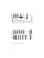
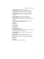
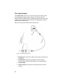
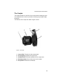
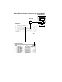
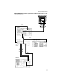
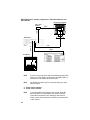
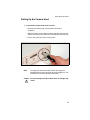
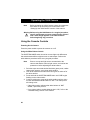
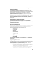
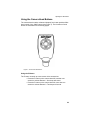
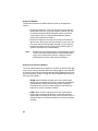
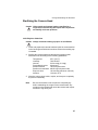
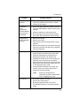
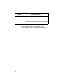
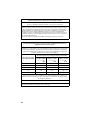
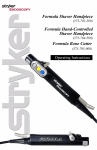
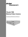
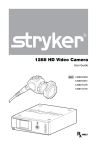
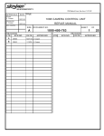
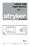
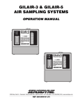
Table of Contents
Table of Contents
Table of Contents . . . . . . . . . . . . . . . . . . . . . . . . . . . . . 1
Warnings and Cautions . . . . . . . . . . . . . . . . . . . . . . . . 3
Symbol Definitions
................................5
Product Description and Intended Use . . . . . . . . . 7
The Camera Console .
..............................7
The Camera Head . . . . . . . . . . . . . . . . . . . . . . . . . . . . . . . . 10
The Coupler . . . . . . . . . . . . . . . . . . . . . . . . . . . . . . . . . . . . 11
Setting Up the 1088 Camera . . . . . . . . . . . . . . . . . . 12
. . . . . . . . . . . . . . . . . . . . . . . . . . . . 12
Setting Up the Camera Head . . . . . . . . . . . . . . . . . . . . . . . . . 17
Setting Up the Coupler. . . . . . . . . . . . . . . . . . . . . . . . . . . . . 18
Setting Up the Console
Operating the 1088 Camera . . . . . . . . . . . . . . . . . . . 20
Using the Console Controls . . . . . . . . . . . .
Powering On the Camera . . . . . . . . . . . .
Using the White Balance Switch . . . . . . . .
Using the Gain Button . . . . . . . . . . . . . .
Using the Enhance (Up and Down) Buttons
Selecting a Surgical Specialty . . . . . . . . .
Using the Light/Zoom Switch . . . . . . . . . .
Using the Shutter Switch . . . . . . . . . . . . .
Using the NTSC/PAL Switch . . . . . . . . . .
Controlling Remote Video Accessories . . .
. . . . . . . . . . . . . 20
. . . . . . . . . . . . . 20
. . . . . . . . . . . . . 20
. . . . . . . . . . . . . 21
. . . . . . . . . . . . . 21
. . . . . . . . . . . . . 21
. . . . . . . . . . . . . 21
. . . . . . . . . . . . . 22
. . . . . . . . . . . . . 22
. . . . . . . . . . . . . 22
Using the Camera Head Buttons . . . . . . . . . . . . . . . . . . . . . . 23
Using the P Button . . . . . . . . . . . . . . . . . . . . . . . . . . . . . . 23
Using the W Button . . . . . . . . . . . . . . . . . . . . . . . . . . . . . 24
Using the Up and Down Buttons . . . . . . . . . . . . . . . . . . . . . 24
Cleaning and Maintaining the 1088 Camera . . . 25
Cleaning the Camera Console.
. . . . . . . . . . . . . . . . . . . . . . . 25
1
Cleaning the Camera Head .
. . . . . . . . . . . . . . . . . . . . . . . . . 25
. . . . . . . . . . . . . . . . . . . . . . . 26
Sterilizing the Camera Head . . . . . . . . . . . . . . . . . . . . . . . . . 27
100% Ethylene Oxide Gas . . . . . . . . . . . . . . . . . . . . . . . . 27
Steris System . . . . . . . . . . . . . . . . . . . . . . . . . . . . . . . . . 28
Sterrad System . . . . . . . . . . . . . . . . . . . . . . . . . . . . . . . . 28
Using Sterile Drapes . . . . . . . . . . . . . . . . . . . . . . . . . . . . 29
Maintaining the 1088 Camera . . . . . . . . . . . . . . . . . . . . . . . . 29
Replacing the Fuses . . . . . . . . . . . . . . . . . . . . . . . . . . . . 29
Periodic Maintenance Schedule . . . . . . . . . . . . . . . . . . . . . 29
Disposing of the 1088 . . . . . . . . . . . . . . . . . . . . . . . . . . . . 29
Disinfecting the Camera Head.
Troubleshooting. . . . . . . . . . . . . . . . . . . . . . . . . . . . . . 30
Electromagnetic Compatibility Tables . . . . . . . . . 33
Technical Specifications . . . . . . . . . . . . . . . . . . . . . . 37
Warranty . . . . . . . . . . . . . . . . . . . . . . . . . . . . . . . . . . . . . 39
Service and Claims . . . . . . . . . . . . . . . . . . . . . . . . . . . 40
International Service . . . . . . . . . . . . . . . . . . . . . . . . . 41
2
Warnings and Cautions
Warnings and Cautions
Please read this manual and follow its instructions carefully. The words
warning, caution, and note carry special meanings and should be
carefully reviewed:
Warning The personal safety of the patient or physician may be
involved. Disregarding this information could result in
injury to the patient or physician.
Caution Special service procedures or precautions must be
followed to avoid damaging the instrument.
Note
Special information to make maintenance easier or
important information more clear.
An exclamation mark within a triangle is intended to alert
the user to the presence of important operating and
maintenance instructions in the literature accompanying
the product.
A lightning bolt within a triangle is intended to warn of the
presence of hazardous voltage. Refer all service to
authorized personnel.
Warning To avoid potential serious injury to the user and
patient, and/or damage to this device, the user must:
1.
Read this operating manual thoroughly and be familiar with
its contents prior to using this equipment.
2.
Carefully unpack the unit and check if any damage
occurred during shipment. If damage is detected, please
refer to the Service and Claims section in this manual.
3.
Be a qualified physician, having complete knowledge of the
use of this equipment.
4.
Test this equipment prior to a surgical procedure. This unit
was fully tested at the factory before shipment.
5.
Avoid removing covers on the control unit, as doing so may
break the camera-head seals or cause electric shock.
6.
Attempt no internal repairs or adjustments not specifically
detailed in this operating manual.
7.
Pay close attention to the care and cleaning instructions in
this manual. A deviation may cause damage.
3
8.
Never sterilize the camera console.
9.
Disconnect the control unit from the electrical outlet when
inspecting the fuses.
10.
Read the entire instruction manual before assembling or
connecting the unit.
11.
Before each use, check the outer surface of the endoscope
to ensure that there are no rough surfaces, sharp edges, or
protrusions.
The warranty is void if any of these warnings is disregarded.
Stryker Endoscopy accepts full responsibility for the effects on safety,
reliability, and performance of the equipment only if:
•
Readjustments, modifications, and/or repairs are carried out
exclusively by Stryker Endoscopy.
•
The electrical installation of the relevant operating room complies
with the applicable IEC, CEC, and NEC requirements.
Stryker Endoscopy reserves the right to make improvements to the
product(s) described herein. Product(s), therefore, may not agree in detail
to the published design or specifications. All specifications are subject to
change without notice. Please contact the local Stryker Endoscopy
Distributor listed in the Other Service section, or phone your local Stryker
Endoscopy sales representative or agent for information on changes and
new products.
Warning Federal law (United States of America) restricts this
device to use by, or on order of, a physician.
4
Warnings and Cautions
Symbol Definitions
In addition to the cautionary symbols already listed, other symbols found
on the 1088 Camera and in this manual have specific meanings that
clarify the proper use and storage of the 1088 Camera. The following list
defines the symbols associated with this product.
Operating humidity ratings
Operating pressure ratings
Operating temperature ratings
Denotes compliance to CAN/CSA C22.2 No 601.1-M90
and UL2601-1.
Type BF applied part
Equipotentiality
Protective earth ground
5
6
Product Description and Intended Use
Product Description and Intended Use
The Stryker Endoscopy Model 1088 Medical Video Camera is a highdefinition camera used to capture still and video images of endoscopic
surgical applications. The 1088 Medical Video Camera consists of three
main components:
• the camera console
• the camera head
• the focusing coupler
The 1088 also comes with various cables, which like the other
components, can be purchased together or separately.
The Camera Console
The camera console is the control center for the 1088 Medical Video
Camera and processes the video and photographic images captured
during the surgical procedure. The front console panel features controls
for adjusting the enhance, gain, and white balance, and for selecting
surgical specialty settings that optimize camera performance for specific
surgical procedures.
The rear console panel provides ports for connecting the 1088 Camera to
viewing and recording equipment, such as video monitors, the SDC HD,
or photo printers.
The features of the front and rear console panels are listed in Figure 1.
7
1
2
3
4
5
6
7
Figure 1a: The 1088 Camera console, front panel
8
9
16 17 18
10
19
11
20
12
21
Figure 1b: The 1088 Camera Console, rear panel
8
14 15
13
22
23
Product Description and Intended Use
1. Power Switch: Powers the camera on and off
2. White Balance Button: Starts the white balance operation
3. Gain Button: Selects four levels of light sensitivity settings
4. Enhance Buttons: Increase or decrease image sharpness
5. Specialty Screen: Displays which surgical preset has been
selected
6. Specialty Button: Selects different surgical presets
7. Camera Connector: Connects to the 1088 Camera Head
8. Sidne™ Port: Connects to the Sidne™ Console to enable voice
operation
9. Ethernet Port: Provides an ethernet connection for remote
diagnoses and future software upgrades
10. RGB Out
11. S-Video 1 Out
12. S-Video 2 Out
13. Composite Out
14. AC Power Inlet
15. Equipotential Ground Plug
16. Light/Zoom Switch: Selects either the LIGHT or ZOOM function
for the arrow buttons on the camera head
17. NTSC / PAL Switch: Selects NTSC or PAL video signals for
analog outputs
18. Shutter Switch: Enables / disables the auto shutter
19. Remote Out 1: Connects to a video accessory remote switch
20. Remote Out 2: Connects to a video accessory remote switch
21. DVI Out 1
22. DVI Out 2
23. Fuse Panel: Contains two 0.63A fuses
9
The Camera Head
The camera head connects to the camera console and captures video
and photographic images, which it relays to the camera console. It
features several controls that are accessible through a button control pad
located on the top of the camera head (see the Operating the Camera
Head section of this manual).
Figure 2 below lists the features of the camera head.
1
2
3
4
Figure 2: The 1088 HD Camera Head
1. Soaking Cap: Protects the cable connector during cleaning and
sterilization
2. Camera Head: Captures photographic and video images,
provides camera controls, and connects to a focusing coupler
3. Camera Cable
4. Cable Connector: Connects the camera head to the camera
console
10
Product Description and Intended Use
The Coupler
The coupler threads on to the face of the camera head, enabling a scope
to be attached to the camera. It provides a focusing ring to adjust image
sharpness.
The features of the coupler are listed in Figure 3 below.
3
2
4
1
5
Figure 3: The coupler
1. Camera End: Threads onto the camera head
2. Focusing Ring: Adjusts the coupler focus
3. Ventilation Port: Provides ventilation for the coupler lens
4. Endobody Clamp: Secures the scope to the coupler
5. Scope End: Receives the endoscope
11
Setting Up the 1088 Camera
Note
Stryker Endoscopy considers instructional training, or inservice, as an integral part of the 1088 Medical Video
Camera. Your local Stryker Endoscopy sales
representative will perform at least one in-service at your
convenience to help set up your equipment and instruct
you and your staff on its operation and maintenance. To
schedule an in-service, contact your local Stryker
Endoscopy representative after your equipment has
arrived.
Setting Up the 1088 Camera involves three steps:
1. Setting up the console
2. Setting up the camera head
3. Setting up the coupler
Setting Up the Console
Caution Portable and mobile RF communications equipment may
affect the normal function of the 1088 Camera. When
choosing a location for the 1088 Camera, consult the
“Electromagnetic Compatibility” section of this manual to
ensure proper function.
To set up the console, make the following connections:
1. Connect the AC power.
• Connect the AC power cord to the AC inlet on the rear console
panel.
• Connect the other end to a hospital-grade outlet.
Warning Always use the hospital-grade power cord supplied
with this camera.
12
Setting Up the 1088 Camera
2. Connect the video output.
• The rear panel provides four analog and two digital-video
outputs, which can be used together or independently:
Output Type
Output
Cable
Connector
Analog
RGB
RGB
8-pin DIN (push-only
connectors)
Composite
Composite
BNC (push-and-turn
connectors)
*S-VHS 1
S-VHS
4 pin Mini-Din (push-only
connectors)
*S-VHS 2
S-VHS
4 pin Mini-Din (push-only
connectors)
**DVI-I 1
DVI
29-pin (push-only
connectors, with two
tightening knobs)
**DVI-I 2
DVI
29-pin (push-only
connectors, with two
tightening knobs)
*On some monitors, SVHS inputs may be
labeled Y/C.
Digital
**The DVI connectors can
also output analog SXGA
signals through a DVI-I to
VGA adapter.
• Use the cables and outputs described above to connect the
1088 to other operating-room equipment. Diagrams 1-3 on the
following pages describe typical set-ups.
• If desired, connect any remote outputs using the remote cables
supplied with the 1088 Camera. (See Diagram 2.) Devices
connected to the remote outputs of the 1088 Camera can be
operated by using the buttons on the camera head. See the
“Operating the Camera Head” section of this manual for details.
• If desired, connect the Sidne™ interface as well. (See Diagram
2.)
Warning When the 1088 Camera is used with other equipment,
leakage currents may be additive. Ensure that all
systems are installed according to the requirements of
IEC 60601-1-1.
Warning Do not touch the internal pin of the VIDEO-OUT BNC
jack and the patient simultaneously.
13
Wiring Diagram 1: Camera, Light Source and Flat-Panel Monitor
Flat-Panel Monitor
DVI-I / VGA
Adapter
DVI
1088 Camera
DVI
BNC
X7000 Light Source
14
Setting Up the 1088 Camera
Wiring Diagram 2: Camera, Light Source, SDC Pro HD, Sidne™, and
Flat-Panel Monitor
StrykerVision 1 Monitor
USB
DVI
Sidne™
DVI
BNC
1088 Camera
X7000 Light Source
Remote
Remote
DVI
SDC HD
15
Wiring Diagram 3: Camera, Light Source, Flat-Panel Monitor, and
CRT Monitor
StrykerVision 1 Monitor
DVI-I / VGA
Adapter
VGA
DVI
1088 Camera
S-VHS
DVI
BNC
X7000 Light Source
CRT Monitor
Note
If you are using any device with unterminated analog video
inputs, you must connect a cable from the VIDEO OUT of
that device to the VIDEO IN on the monitor.
Note
An additional monitor may be connected using any open
camera output.
3. Power on the monitor.
4. Power on the camera.
Note
16
A color bar pattern will appear on the monitor when the
camera head is not connected to the camera console.
Follow the instructions in the “Setting Up the Camera
Head” section of this manual to connect the camera head
to the console.
Setting Up the 1088 Camera
Setting Up the Camera Head
1. Connect the camera head to the console.
• Unscrew the soaking cap from the cable connector if
necessary.
• Align the red dot on the cable connector with the red dot on the
camera-connector port on the front console panel (see Figure 4).
• Push in the connector until it locks in place.
Figure 4: Connecting the camera head to the console
Note
To unplug the camera from the control unit, grasp the
knobbed portion of the connector and pull straight out. This
releases the connector latching mechanism.
Caution Do not severely bend the camera cable or damage may
result.
17
Setting Up the Coupler
1. Attach the coupler to the camera head.
• Twist the camera end of the coupler into the camera head
(clockwise) until it forms a tight seal (see Figure 5).
Figure 5: Attaching a coupler to the camera head
Caution Do not overtighten the coupler, as this may damage
the front window of the camera.
Note
For direct-coupled scopes (scopes that require no coupler),
thread the endoscope directly into the camera head until it
forms a tight seal.
Caution Do not overtighten a direct-coupled scope, as this may
damage the front window of the camera.
18
Setting Up the 1088 Camera
2. Attach an endoscope to the coupler.
• Remove the red dust cap if it is present.
• Push down on the endobody clamp (a) and insert the scope
into the scope end of the coupler (b). (See Figure 6.)
(a)
(c)
(b)
Figure 6: Attaching an endoscope to the camera head
• Release the endobody clamp.
3. Attach a light cable from the light source to the light post on
the endoscope (c) (see Figure 6).
Warning Before each use, check the outer surface of the
endoscope to ensure there are no rough surfaces,
sharp edges, or protrusions.
19
Operating the 1088 Camera
Note
Before operating the 1088 Camera, ensure all components
have been set up according to the instructions in the
“Setting Up the 1088 Camera” section of this manual.
Warning Before using the 1088 Camera in a surgical procedure,
test all components to ensure proper function. Ensure
that a video image appears on all video monitors
before beginning any procedure.
Using the Console Controls
Powering On the Camera
Press the power switch to power the camera on or off.
Using the White Balance Switch
The WHITE BALANCE switch is used to correct slight color differences
that exist between different light sources or endoscopes. Perform the
white balance procedure before every surgical procedure.
Note
Ensure a scope and light source are attached to the
camera and that the camera, light source, and monitor are
powered on before adjusting the white balance.
1. Point the scope at several stacked 4x4 white gauze pads, a white
laparoscopic sponge, or any clean white surface.
2. Look at the monitor and make sure that no glare is visible off of
the white surface.
3. Press and hold the WHITE BALANCE button until “WB” begins
flashing on the video monitor.
4. Continue pointing the scope at the white surface until the video
monitor indicates that white balance is “OK.” The video picture
will change color.
• If the video monitor indicates that white balance is “NOT
GOOD,” repeat the process.
• If you cannot achieve a white balance that is “OK,” refer to the
“Troubleshooting” section of this manual.
20
Operating the 1088 Camera
Using the Gain Button
The GAIN button increases the brightness of the video picture. If the
picture is too dark even when the light source is at full brightness and the
camera light level is maximized, you can brighten the picture by
increasing the gain. When you increase the gain, the picture will get
brighter but may also be more grainy.
There are four levels of gain: OFF, LOW, MEDIUM, and HIGH. Press the
GAIN button repeatedly to scroll through the four levels. The current gain
level will be displayed on the monitor. OFF is the setting you should
normally use.
Using the Enhance (Up and Down) Buttons
The Enhance buttons increase or decrease the picture sharpness.
There are 16 levels of enhancement. The current enhancement level will
be displayed on the monitor.
Selecting a Surgical Specialty
The Surgical Specialty switch selects one of eight pre-established camera
settings. Each camera setting optimizes camera performance for a
specific surgical application. The eight settings are
• Arthroscopy
• Cystoscopy
• Standard
• Thoracoscopy
• Laparoscopy
• ENT
• Microscope
• Flex Scope
The selected type will display on the specialty screen on the 1088 front
console panel.
Using the Light/Zoom Switch
The Light/Zoom switch on the rear console panel determines the function
of the arrow buttons on the camera head. (See also the “Using the
Camera Head Buttons” section of this manual.)
• Place the Light/Zoom switch in the Zoom position to make the
arrow buttons on the camera head control zoom.
• Place the Light/Zoom switch in the Light position to make the
arrow buttons on the camera head control the light level.
21
Using the Shutter Switch
The SHUTTER switch on the rear console panel activates or deactivates
the automatic shutter.
• Select “ON” to enable the automatic shutter. The camera will
automatically adjust picture brightness in response to varying
light levels.
• Select “OFF” to disable the automatic shutter. You will adjust
picture brightness by using an automatic light source.
Note
You may use an automatic light source and the camera
auto shutter at the same time, but the camera auto shutter
should normally be used alone.
Using the NTSC/PAL Switch
The NTSC/PAL switch selects which type of analog output the camera
will use.
• Choose NTSC for NTSC analog outputs (Composite, S-VHS,
RGB).
• Choose PAL for PAL analog outputs.
Controlling Remote Video Accessories
The 1088 Camera can remotely control two video accessories (such as
the SDC Pro, a VCR, or a photo printer), enabling the user to capture
images or start and stop video recording by pressing the buttons on the
camera head. (See also the “Using the Camera Head Buttons” section of
this manual.)
1. Connect the video accessory to one of the remote outputs on the
rear console panel. Use the provided remote cables. (See
Diagram 2 in the “Setting Up the Console” section of this
manual.)
2. Press the ‘P’ button on the camera head for less than one second
to activate Remote 1. One beep will sound.
3. Press the ‘P’ button on the camera head for more than one
second to activate Remote 2. Two beeps will sound.
22
Operating the 1088 Camera
Using the Camera Head Buttons
The camera head contains a diamond-shaped, four-button pad that offers
hand control of the 1088 Camera (see Figure 7). The functions of each
button are described in the following pages.
Figure 7: The camera head buttons.
Using the P Button
The P button controls up to two remote video accessories.
• Press the P button on the camera head for less than one
second to activate Remote 1. One beep will sound.
• Press the P button on the camera head for more than one
second to activate Remote 2. Two beeps will sound.
23
Using the W Button
The W button activates the white-balance function or the light/zoom
function.
• Press the W button for more than one second to activate the
white-balance function. (The white-balance function may also
be initiated using the WHITE BALANCE switch on the front
console panel. See the “Using the White Balance Switch”
section of this manual for details.)
• Press the W button for less than one second to increase the
light or zoom. Each press will raise the light or zoom level one
out of four total increments. When the light or zoom level has
reached its maximum level, pressing the W button again will
cycle the level back to the lowest setting.
Note
Whether the button selects light or zoom depends on which
function has been selected with the LIGHT/ZOOM switch
on the rear console panel. (See the “Using the LIGHT/
ZOOM Switch” section of this manual for details.)
Using the Up and Down Buttons
The up and down buttons work together to increase or decrease the light
level or zoom settings. Whether the button selects light or zoom depends
on which function has been selected with the LIGHT/ZOOM switch on the
rear console panel. (See the “Using the LIGHT/ZOOM Switch” section of
this manual for details.)
• ZOOM: When ZOOM is selected on the rear console panel,
pressing the arrow buttons will raise or lower the magnification
setting between 100 percent and 200 percent in 64 steps.
Press the button once for individual steps or hold down the
button for a quicker, smoother transition.
• LIGHT: When LIGHT is selected on the rear console panel,
pressing the arrow buttons will raise or lower the automaticshutter light-level setting in 64 steps. Press the button once for
individual steps or hold down the button for a quicker, smoother
transition.
24
Cleaning and Maintaining the 1088 Camera
Cleaning and Maintaining the 1088 Camera
Cleaning the Camera Console
Warning Disconnect the console from the AC power source
before cleaning.
Should the camera console need cleaning, wipe it down with a sterile
cloth and mild cleaning solution.
Caution Never immerse or sterilize the camera console as this
will damage the camera and void the warranty.
Cleaning the Camera Head
Warning The camera head and cable must be cleaned and
sterilized prior to the first use and after every
subsequent use.
1. Immediately after use, unplug the camera-head connector from
the console and protect it with the soaking cap. Place the cap
over the connector and turn it clockwise until secure.
Caution Always install the soaking cap before rinsing the
camera. Failure to properly tighten the soaking cap will
corrode the connector pins and void the warranty.
2. Rinse the camera head and cable in lukewarm tap water. Use a
mild enzymatic detergent and a soft brush to remove resistant
debris and bioburden from all surfaces.
3. Rinse off all soap residue with water.
4. Clean glass surfaces with alcohol.
5. Dry the camera head and cable thoroughly with a soft towel or
gauze surgical sponge.
6. Prepare the camera head and cable for disinfection by coiling the
camera cable into a loop about ten inches in diameter, avoiding
any kinks or twists in the cable.
25
Disinfecting the Camera Head
Caution Before soaking, inspect the camera cable for cuts and
breaks. Never soak a cut or a broken cable because
moisture will seep into the camera head and cause
damage. Return any camera with a damaged cable to
the Stryker Endoscopy Repair Department for service.
Never soak the camera and cable in the same tray with
sharp instruments.
Caution Separate the camera head, coupler, and scope prior to
disinfection. Refer to the coupler and scope product
manuals for disinfection instructions.
Caution Always install the soaking cap prior to disinfection.
Caution To minimize galvanic corrosion, avoid soaking
dissimilar metals in close proximity.
Caution Avoid leaving the camera in sterilization solutions
longer than necessary, as this will accelerate normal
product aging. Camera life is extended by the
consistent use of a single sterilization method.
1. Clean and prepare the camera head and cable as recommended
in the Cleaning section. Ensure the soaking cap is installed.
2. Immerse the camera head and cable in Cidex Plus®
glutaraldehyde solution or Cidex OPA® solution for disinfecting.
Specifications for each are as follows:
Cidex Plus® disinfection:
Soak time:
10 minutes minimum, as recommended by the
sterilant manufacturer (24 hours maximum)
Temperature: 25°C (77°F)
Cidex OPA® disinfection:
Soak time:
12 minutes minimum, as recommended by the
sterilant manufacturer (24 hours maximum)
Temperature: 20°C (68°F)
3. After soaking, rinse the camera head and cable in sterile water,
agitating them to remove all traces of glutaraldehyde solution.
4. Dry all parts thoroughly with a sterile towel.
26
Cleaning and Maintaining the 1088 Camera
Sterilizing the Camera Head
Caution If the coupler and camera head are sterilized as a
single unit, disconnecting the coupler will compromise
the sterility of the two products.
100% Ethylene Oxide Gas
Caution Always install the soaking cap prior to sterilization.
1. Clean and prepare the camera head and cable as recommended
in the Cleaning and Disinfection sections. Ensure the soaking cap
is installed.
2. Sterilize the camera head and cable with an ethylene oxide
sterilization unit according to the following parameters:
Temperature:
Humidity:
Vacuum:
Preconditioning time:
Sterilant mixture:
Sterilant concentration:
Exposure time:
Aeration:
55°C (131°F)
70% RH±5%
53.34 cmHg (21 inHg)
60 minutes
100% ethylene oxide
600±5 mg/L ethylene oxide
120 minutes (maximum 180 min.)
12 hours, 55°C
3. Allow the camera head, cable, coupler, and scope to completely
dry before reassembly.
Note
Be sure the threads on the coupler are completely dry
before reattaching the coupler to the camera head. Any
moisture on the threads will cause the camera and coupler
windows to fog during use.
27
Steris System
Caution Always install the soaking cap prior to sterilization.
1. Clean and prepare the camera head and cable as recommended
in the Cleaning and Disinfection sections. Ensure the soaking cap
is installed.
2. Sterilize the camera head and cable using Steris® System 1 with
Steris® Sterilant 20.
3. Allow the camera head, cable, coupler, and scope to completely
dry before reassembly.
Note
Be sure the threads on the coupler are completely dry
before reattaching the coupler to the camera head. Any
moisture on the threads will cause the camera and coupler
windows to fog during use.
Sterrad System
Caution Always install the soaking cap prior to sterilization.
1. Clean and prepare the camera head and cable as recommended
in the Cleaning and Disinfection sections. Ensure the soaking cap
is installed.
2. Sterilize the camera head and cable using the Sterrad™
Sterilization System.
3. Allow the camera head, cable, coupler, and scope to completely
dry before reassembly.
Note
28
Be sure the threads on the coupler are completely dry
before reattaching the coupler to the camera head. Any
moisture on the threads will cause the camera and coupler
windows to fog during use.
Cleaning and Maintaining the 1088 Camera
Using Sterile Drapes
Using sterile drapes will ensure maximum longevity of your 1088 Camera
Head. For best results, follow the instructions provided by the drape
manufacturer. Sterile camera drapes for use with the 1088 Camera Head
can be ordered under Stryker product number 240-010-200.
Maintaining the 1088 Camera
Replacing the Fuses
1. Unplug the power cord from the wall outlet and remove the cord
from the camera console.
2. Unlatch the fuse holder above the AC inlet and remove it. (You
may need to press the tab on the fuse holder with a slender
screwdriver to release the latch.)
3. Replace the fuse with the same value and rating.
Warning To avoid the risk of fire, only use fuses of the value
specified on the fuse label located on the rear panel of
the camera control unit.
4. Reinstall the fuse holder until the tab snaps in place.
Periodic Maintenance Schedule
Warning To ensure safe operation of the Model 1088 Medical
Video Camera you should perform the following
procedure periodically:
Every 12 months, check the earth leakage current to <500µA (<300µA in
U.S.A.), ground impedance to <0.1 ohms, and power consumption less
than or equal to rated power. Use a true RMS digital multimeter and
safety analyzer to perform this test.
Note
Refer calibration and operating difficulties not detailed in
this manual to your Stryker Endoscopy sales
representative.
Disposing of the 1088
The 1088 must be disposed of according to local laws and hospital
practices. The device does not contain any hazardous materials.
29
Troubleshooting
Problem
No color bar
Possible Solution
• Ensure the video-out from the camera is
connected to the video-in on the monitor.
• Ensure all video systems are powered on.
Incorrect picture
color
• Perform the white balance procedure. (See the
“Using the White Balance Switch” section of this
manual.)
• Check the color settings on the monitor.
Picture is too
dark
• Adjust the light level with the camera head.
• Increase the light-source output.
• Check the fiberoptic light cable for excessive
broken fibers.
• Press the GAIN switch to increase illumination.
Picture is too
bright
• Adjust the light level with the camera head.
• Decrease the light-source output.
• Ensure GAIN is OFF.
Noise or snow on
picture when
using
electrocautery
probes
• Plug the electrocautery generator into a
separate electrical outlet and separate the 1088
power cord from the electrocautery power cord.
• Separate the camera cable from the
electrocautery cable
• Reposition the electrocautery grounding pad on
the patient.
Noise or snow on
picture when not
using
electrocautery
probes
• Ensure GAIN is OFF.
No video picture
when the camera
head is plugged
in
• Check to ensure that all devices in the video
system are plugged in and powered on.
30
• Reduce Enhancement.
• Check for and replace faulty video cables.
• Check the connector on the camera-head cable
for broken pins.
Troubleshooting
Problem
Possible Solution
Image is not
centered
• Release the scope from the coupler and then
reconnect it. Make sure the scope is seated
correctly in the coupler.
Variability in
color
reproduction
between different
light sources or
peripherals
• Perform the white-balance procedure. (See the
“Using the White Balance Switch” section of this
manual.)
Foggy picture
(loss of definition
& clarity)
• Refocus the camera.
• Check the settings on video peripherals.
• Ensure the light source has a proper infrared
filter (check with manufacturer specifications).
• Refocus the coupler.
• Clean and dry both the scope and the coupler
windows.
• Remove the coupler from the camera head and
remove any moisture that has built up between
the two components.
Optics are dirty
• Rotate the scope. If dust particles in the picture
rotate, the dust is located on the scope itself.
Follow the manufacturer’s instructions for
cleaning the eyepiece and negative lens.
• If particles in the picture do not move when you
rotate the scope, the particles are located
behind the scope. Remove the scope and clean
the window on the front of the coupler with a dry
or alcohol-tipped cotton swab.
• If dust particles lie between the coupler and
camera, remove the coupler and clean the
coupler and camera windows.
Note
Blurry picture
Ensure all components are
completely dry before reassembling
them, or fogging may result.
• Ensure the coupler is in focus.
• Increase the enhancement.
• Ensure the specialty switch is not set to
FLEXSCOPE unless you are using a flexible
scope.
31
Problem
White balance
(WB) not good
Possible Solution
• See the solution for “Picture is too dark.”
• See the solution for “Picture is too bright.”
• Perform the white-balance procedure with the
light source connected to the scope. Use metalhalide or xenon lighting (no fluorescent lighting).
Note
32
If this troubleshooting guide does not solve the problems
that you are having with your camera, call Stryker
Technical Support at 1-877-478-7953 (inside the U.S.) or
refer to the “Service and Claims” section of this manual.
Electromagnetic Compatibility Tables
Electromagnetic Compatibility
Like other electrical medical equipment, the 1088 Camera requires
special precautions to ensure electromagnetic compatibility with other
electrical medical devices. To ensure electromagnetic compatibility
(EMC), the 1088 Camera must be installed and operated according to the
EMC information provided in this manual.
Note
The 1088 Camera has been designed and tested to comply
with IEC 60601-1-2:2001 requirements for EMC with other
devices.
Caution Portable and mobile RF communications equipment may
affect the normal function of the 1088 Camera.
Warning Do not use cables or accessories other than those
provided with the 1088 Camera, as this may result in
increased electromagnetic emissions or decreased
immunity to such emissions.
Warning If the 1088 Camera is used adjacent to or stacked with
other equipment, observe and verify normal operation
of the 1088 Camera in the configuration in which it will
be used prior to using it in a surgical procedure.
Consult the tables below for guidance in placing the
1088 Camera.
Guidance and Manufacturer's Declaration: Electromagnetic Emissions
1088 Camera is intended for use in the electromagnetic environment specified below. The customer
or the user of 1088 Camera should ensure that it is used in such an environment.
Emissions test
Compliance
Electromagnetic Environment - guidance
RF emissions CISPR
11
Group 1
1088 Camera uses RF energy only for its
internal function; therefore, its RF emissions are
very low and are not likely to cause any
interference in nearby electronic equipment.
RF emissions CISPR
11
Class B
Harmonic emissions
IEC61000-3-2
Class A
Voltage Fluctuations/
flicker emissions
IEC61000-3-3
Complies
1088 Camera is suitable for use in all
establishments, including domestic
establishments and those directly connected to
the public low-voltage power supply network
that supplies buildings used for domestic
purposes.
33
Guidance and Manufacturer's Declaration: Electromagnetic Immunity
1088 Camera is intended for use in the electromagnetic environment specified below. The customer
or
the user of 1088 Camera should ensure that it is used in such an environment.
Immunity Test
Electrostatic Discharge
(ESD)
IEC61000-4-2
Electrical fast transient/
burst
IEC61000-4-4
Surge
IEC61000-4-5
Voltage dips, short
interruptions and voltage
variations on power supply
input lines
IEC61000-4-11
Power frequency (50/60Hz)
magnetic field
IEC 60601 Test
Level
Compliance Level
±6kV contact
±2,4,6kV contact
±8kV air
±2,4,8kV air
±2kV for power
supply lines
±2kV line to ground
±1kV for input/
output lines
±1kV line to line
±1kV differential
mode
±0.5, 1kV
differential mode
±2kV common
mode
±0.5, 1, 2kV
common mode
<5% Ut (>95% dip
in Ut) for 0.5 cycle
<5% Ut (>95% dip
in Ut) for 0.5 cycle
40% Ut (60% dip in
Ut) for 5 cycles
40% Ut (60% dip in
Ut) for 5 cycles
70% Ut (30% dip in
Ut) for 25 cycles
70% Ut (30% dip in
Ut) for 25 cycles
<5% Ut (>95% dip
in Ut) for 5 sec.
<5% Ut (>95% dip
in Ut) for 5 sec.
3 A/m
N/A
IEC 61000-4-8
NOTE: Ut is the a.c. mains voltage prior to application of the test level.
34
Electromagnetic
Environment:
Guidance
Floors should be
wood, concrete, or
ceramic tile. If floors
are covered with
synthetic material,
the relative humidity
should be at least
30%.
Mains power quality
should be that of a
typical commercial
or hospital
environment.
Mains power quality
should be that of a
typical commercial
or hospital
environment.
Mains power quality
should be that of a
typical commercial
or hospital
environment. If the
user of 1088
Camera requires
continued operation
during power mains
interruptions, it is
recommended that
1088 Camera be
powered from an
uninterruptible
power supply or a
battery.
Power-frequency
magnetic fields
should be at levels
characteristic of a
typical location in a
typical commercial
or hospital
environment.
Electromagnetic Compatibility Tables
Guidance and Manufacturer's Declaration: Electromagnetic Immunity
1088 Camera is intended for use in the electromagnetic environment specified below. The customer or
the user of 1088 Camera should ensure that it is used in such an environment.
Immunity
Test
IEC 60601 Test
Level
Compliance
Level
Electromagnetic Environment:
Guidance
Portable and mobile RF communications
equipment should be used no closer to
any part of the 1088 Camera system,
including its cables, than the
recommended separation distance
calculated from the equation applicable to
the frequency of the transmitter.
Recommended Separation Distance
Conducted RF
3 Vrms
IEC 61000-4-6
150 kHz to 80 MHz
Radiated RF
3 V/m
IEC 61000-4-3
80MHz to 2.5 GHz
3V
3 V/m
d = 1.17 P
d = 1.17 P 80 MHz to 800 MHz
d = 2.33 P 800 MHz to 2.5 GHz
where P is the maximum output power
rating of the transmitter in watts (W)
according to the transmitter manufacturer
and d is the recommended separation
distance in meters (m).
Field strengths from fixed RF transmitters,
as determined by an electromagnetic site
survey (a), should be less than the
compliance level in each frequency
range(b).
Interference may occur in the vicinity of
equipment marked with the following
symbol:
NOTE 1: At 80 MHz and 800 MHz, the higher frequency range applies.
NOTE 2: These guidelines may not apply in all situations. Electromagnetic propagation is affected by
absorption and reflection from structures, objects, and people.
35
Guidance and Manufacturer's Declaration: Electromagnetic Immunity
1088 Camera is intended for use in the electromagnetic environment specified below. The customer or
the user of 1088 Camera should ensure that it is used in such an environment.
(a) Field strengths from fixed transmitters, such as base stations for radio (cellular/cordless)
telephones and land mobile radios, amateur radio, AM and FM radio broadcast, and TV broadcast,
cannot be predicted theoretically with accuracy. To assess the electromagnetic environment due to
fixed RF transmitters, an electromagnetic site survey should be considered. If the measured field
strength in the location in which the 1088 Camera system is used exceeds the applicable RF
compliance level above, the 1088 Camera system should be observed to verify normal operation. If
abnormal performance is observed, additional measures may be necessary, such as reorienting or
relocating the 1088 Camera unit.
(b) Over the frequency range 150 kHz to 80 MHz, field strengths should be less than 3 V/m.
Recommended Separation Distances Between Portable and Mobile RF Communications
Equipment and the 1088 Camera System
The 1088 Camera system is intended for use in an electromagnetic environment in which radiated RF
disturbances are controlled. The user of the 1088 Camera system can help prevent electromagnetic
interference by maintaining a minimum distance between portable and mobile RF communications
equipment (transmitters) and the 1088 Camera system as recommended below, according to the
maximum output power of the communications equipment.
Separation distance (m) according to frequency of transmitter
Rated maximum output
power (W) of transmitter
0.01
150 kHz to 80 MHz
80 MHz to 800 MHz
800 MHz to 2.5 GHz
d = 1.17 P
d = 1.17 P
d = 2.33 P
0.12
0.12
0.23
0.1
0.37
0.37
0.74
1
1.17
1.17
2.33
10
3.70
3.70
7.37
100
11.70
11.70
23.30
For transmitters rated at a maximum output power not listed above, the recommended separation
distance (d) in meters (m) can be estimated using the equation applicable to the frequency of the
transmitter, where P is the maximum output power rating of the transmitter in watts (W) according to
the transmitter manufacturer.
NOTE 1: At 80 MHz and 800 MHz, the separation distance for the higher frequency range applies.
NOTE 2: These guidelines may not apply in all situations. Electromagnetic propagation is affected by
absorption and reflection from structures, objects, and people.
36
Technical Specifications
Technical Specifications
Imaging System
1/3” Progressive Scan CCDs
High Definition
Scanning System
Horizontal:
47.536 kHz
Vertical:
60.02 Hz
Video Outputs
Digital/Analog: Two Digital Video Interface (DVI)/RGBHV
1280 x 1024 (SXGA)resolution
Connector:
29-pin DVI-I
Composite:
Connector:
One NTSC or PAL standard 1.0V P-P (75 Ohms)
BNC coaxial
Y/C:
Two S-VHS
Y-1.0V P-P C-0.29V P-P (75 ohms)
4-Pin mini-DIN
Connector:
Component:
Connector:
Resolution
Horizontal:
Vertical:
One RGB
R - 0.7V p-p (75 ohms)
G - 1.0 V p-p (w/ SYNC) (75 ohms)
B - 0.7 V p-p (75 ohms)
8-pin DIN
1100 lines
600 lines
Mounting
Endoscope Eyepiece used with coupler
C-mount camera head used with C-mount scopes
(C-mount 1”-32UN-2A)
Auto Shutter Range
1/60 to 1/50,000 second
Gain
OFF
LOW
MEDIUM
HIGH
0 dB
5 dB
10 dB
15 dB
37
Operating Conditions
Temperature: 0° to 40° C
Relative Humidity:10% to 75%
Transport & Storage Conditions
Temperature: -20° to 60° C
Relative Humidity: 10% to 75%
Atmospheric Pressure: 700 hPa to 1060 hPa
Input Electrical Ratings
100-240V ~ 50/60 Hz 0.6A
Total Shipping Weight
11 lbs (5.0 kg)
Dimensions
Camera Control Unit:
12.5”w x 3.8”h x 15.25”d
(31.8cm w X 9.7cm h X 38.7cm d)
Camera Head Cable to Camera Control Unit:
10.3 feet (3.15m) sealed cable
or 20.7 foot (6.30m) sealed cable (sensed by CCU)
Enhancement
16 levels (switchable)
Classification & Approvals
Complies with medical safety standards:
IEC 60601-1: 1988 + A1: 1991 + A2: 1995
IEC 60601-2-18: 1996 + A1: 2000
CAN/CSA C22.2 No 601.1-M90
UL2601-1: 2nd Edition
AS/NZS 3200.1.0:1998
Complies with medical EMC standard:
IEC 60601-1-2:2001
Class I Equipment
Type BF Applied Part
Water Ingress Protection, IPX0-Ordinary Equipment
Continuous Operation
38
Warranty
Warranty
Stryker Endoscopy warrants the Model 1088 Medical Video Camera
against defects in both materials and workmanship to the registered
owner at the time of purchase. All components including the charge
coupled device (CCD) located in the camera head are covered by the
warranty for a period of one year from the date of purchase.
This warranty does not apply to any unit which has been subject to
misuse, neglect, improper installation or that which has been altered,
adjusted, or tampered with by any person other than Stryker Endoscopy
authorized personnel.
If upon examination by authorized service personnel, it is determined that
the malfunction is due to misuse, or abuse, warranty provisions will not
apply. An estimate of the cost of repair work will be given to the customer
prior to servicing and repairing the unit.
The customer is responsible for returning the defective equipment to the
factory at his or her own expense. Stryker Endoscopy or its
representative will service the unit, repair or replace any defective parts
thereof, and return the unit.
If, upon examination, it is determined that the fault has been caused by
misuse or abnormal conditions of operation, the repairs will be billed to
the customer as out-of-warranty repairs.
Instruments repaired under Stryker Endoscopy’s standard repair program
will be issued a thirty day warranty against defects in both materials and
workmanship, provided the original warranty period has passed.
Instruments submitted due to defects in materials and workmanship
during the warranty period will be repaired at no charge to the customer.
The warranty as set forth herein is exclusive and in lieu of all other
warranties, remedies, obligations and liabilities of Stryker Endoscopy
Inc., expressed or implied, including the implied warranties of
merchantability and fitness for use and of consequential damages. These
products are being sold only for the purpose described herein, and such
warranty only runs to the purchaser. In no event shall Stryker Endoscopy
be liable for any breach of warranty in any amount exceeding the
purchase price of the product.
No agent, employee or representative of Stryker Endoscopy has the
authority to bind the Company to any other warranty, affirmation, or
representation concerning this instrument.
This warranty is valid only to the original purchaser of Stryker Endoscopy
products directly from Stryker Endoscopy or from a Stryker Endoscopy
authorized agent. The warranty cannot be transferred or assigned by the
original purchaser.
39
Service and Claims
Caution Never open the camera head or its cable or attempt any
service not described in this manual. These units have
been factory sealed to prevent moisture from entering
the electronic components. If the camera head or the
cable seal is intentionally broken, the equipment
warranty will be void.
If service is needed either during or after the warranty period:
1. Contact Stryker Endoscopy at 1-800-624-4422 or phone your
local Stryker Endoscopy sales representative.
2. Package all the components carefully in the original shipping
container if possible.
3. Ship the camera, pre-paid and insured to:
Stryker Endoscopy Customer Service
Attention: Repair Department
5900 Optical Court
San Jose, CA 95138
Stryker and Stryker Endoscopy are registered trademarks of Stryker Corporation.
40
International Service
International Service
For service in the USA, call your Stryker Endoscopy representative or
Stryker Endoscopy Customer Service at 1-800-624-4422. Outside of the
USA, please contact your Stryker Endoscopy distributor at one of the
following locations:
Stryker Corporation
2725 Fairfield Road
Kalamazoo, MI 49002
USA
Phone:1-269-385-2600
Telex:224464 STRYKER KMZ
Fax:1-269-385-1996
Stryker European Rep - RA/QA
Manager
ZAC Satolas Green Pusignan
Av. De Satolas Green
69881 MEYZIEU Cedex, France
Phone:33-1-48175000
Fax:33-1-48632175
Stryker Canada
45 Innovation Drive
Hamilton, Ontario, Canada
L9H 7L8
Phone: (905) 690-5700
(800) 668-8323 (toll free)
Fax: +1(905) 690-5698
Stryker India Private Limited
First Floor
C-5, SDA Commercial Complex
New Delhi 110 017
INDIA
Phone:91-11-686-6740
Fax:91-11-696-6020
Stryker Deutschland GmbH
Gewerbeallee 18, D-45478
Mulheim an der Ruhr
GERMANY
Phone:49-208-999-060
Fax:49-208-999-0666
Stryker Australia
No. 50 Broughton Road
Artarmon, NSW 2064
AUSTRALIA
Phone:61-2-9415-5100
Fax:61-29-4294127
Stryker Latin America
15100 N.W. 67th Ave. Suite 210
Miami, Florida 33014
USA
Phone:1-305-821-1888
Fax:1-305-826-0067
Stryker Singapore PTE/LTD
70 Bendemeer Road
#03-32 Hiap Huat House
SINGAPORE 339940
Phone:65-293-0119
Fax:65-293-7028
Stryker B.V.
Marinus van Meelweg 17
P.O. Box 8747
5657 En Eindhoven
THE NETHERLANDS
Phone:31-40-2922522
Fax:31-40-2922555
Stryker Pacific Ltd.
Suite 2501, Citibank Tower
Citibank Plaza
3 Garden Road, Central
HONG KONG
Phone:61-2-9415-5100
Fax:61-29-4294127
Stryker Osteonics, SA
5, Chemin des Aulx 5
1228 Plan-les-Ouates
Case Postale 725
1212 Grand-Lancy 1
Geneve, SWITZERLAND
Phone:41-22-884-0111
Fax:41-22-884-0199
Stryker Mexico, S.A. de C.V.
Calle Sacramento 410
Col. Insurgentes San Borja
C.P. 03100
Mexico, D.F.
MEXICO
Phone:525-488-0890
Fax:525-488-0891
41
Stryker Finland
PL 80 (Makelankatuz)
FIN 00501 Helsinki
FINLAND
Phone:358 (0) 9 7744 680
Fax:358 (0) 9 7744 6820
Stryker Middle East / Africa
Via Della Posta
6934 Bioggio
Switzerland
Phone:(4021) 212-1122
Fax:(4021) 212-1133
Stryker Korea
11F Dong Sung Bldg.
154-24 Samsung-dong
Kangnam-ku
Seoul, KOREA 135-090
Phone:82-2-34517572
Fax:82-2-552-4156
NV Stryker SA (Belgium)
Ikaros Business Park Fase III
Ikaroslaan 12
1930 Zaventem
Brussels, BELGIUM
Phone:32-2-717-92-10
Fax:32-2-717-92-49
Stryker China Limited
Room 903-905, Office Tower 2
Beijing Sun Dong An Plaza
138 Wang Fu Jing Da Jie
Beijing 100006, P.R. China
Phone:86-10-65136183
Fax:86-10-83913571
Stryker Chile
Avenida Nueva Tajamar 481
Oficina 805 Piso 8 Torre Norte
Santiago, CHILE
Phone:562-244-3600
Fax:562-244-3696
Stryker Japan
Dai Tokyo Kasai Shinjuku Bldg.
3-25-3, Yoyogi
Shibuya-ku, Tokyo 151-0053
Phone:813-535-29106
Fax:813-535-21789
Stryker Spain
Manuel Tovar 35
28034 Madrid
SPAIN
Phone:34-91-7283500
Fax:34-91-3580748
Stryker Europe Headquarters
Cite-Centre, Grand Rue 92
CH-1820 Montreux
SWITZERLAND
Phone:41-21-966-1201
Fax:41-21-966-1200
Stryker AB Scandinavia
Krossverksgatan 3
S-216 10 Malmö
SWEDEN
Phone:46 40-69-18-100
Fax:46 40-69-18-190
Stryker Taiwan
5F-1,23 Pa Te Road
Section 1, Taipei, TAIWAN, R.O.C.
Phone:886-2-2322-2895
Fax:886-2-2357-8543
Stryker AB Denmark
Sankt Annae Plads 9
1021 Copenhagen, Denmark
Phone:45 33 9360 99
Fax:45 33 9320 69
Stryker U.K. Ltd.
Hambridge Road
Newbury
Berkshire RG14 5 EP
United Kingdom
Phone:44-1635-262400
Fax:44-1635-262464
MANUFACTURER
Stryker Endoscopy Inc.
5900 Optical Court
San Jose, CA 95138
USA
Phone:408-754-2000
Fax:408-754-2505
42
5900 Optical Court
San Jose, CA 95138
1-800-624-4422
1-800-729-2917
1000-400-675 Rev. A