1
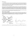
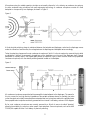
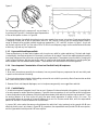
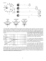
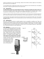
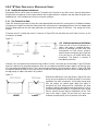
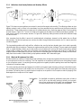
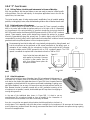
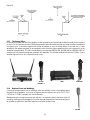
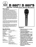
The ABC's of AKG:
Microphone Basics
&
Fundamentals of Usage
Table of Contents
Introduction ................................................................................................................................................................1
1.0.0
“A” How they Work.......................................................................................................................................1
1.1.0 Microphone Pickup Patterns................................................................................................................3
1.1.1 Omnidirectional......................................................................................................................3
1.1.2 Cardioid .................................................................................................................................3
1.1.3 Hypercardioid and Supercardioid.............................................................................................4
1.2.0 Some Important Characteristics of Omni and Cardioid Family of Microphones.....................................4
1.2.1 Omni......................................................................................................................................4
1.2.2 Cardioid Family ......................................................................................................................4
1.3.0 Electrical Aspects of AKG Microphones ...............................................................................................6
1.3.1 Impedance..............................................................................................................................6
1.3.2 Sensitivity ...............................................................................................................................6
1.3.3 Self Noise Level ......................................................................................................................6
1.3.4 Overload Point........................................................................................................................7
1.3.5 Handling Noise .......................................................................................................................7
1.3.6 Powering ................................................................................................................................7
2.0.0
“B” Basic Principles of Microphone Usage....................................................................................................8
2.1.0 Multiple Microphone Interference .......................................................................................................8
2.1.1 The Three-to-One Rule ...........................................................................................................8
2.1.2 Multi-microphones on the Podium ..........................................................................................8
2.1.3 Reflections from Nearby Surfaces and Boundry Effects.............................................................9
2.2.0 Wind and Microphones Don’t Mix ......................................................................................................9
3.0.0
“C” Case Studies..........................................................................................................................................10
3.1.0 Miking Talkers, Vocalist, and Instruments in Houses of Worship ........................................................10
3.1.1 Pulpit and Lectern Microphones ...........................................................................................10
3.1.2 Altar Microphones ................................................................................................................10
3.1.3 The Roving Talker.................................................................................................................11
3.1.4 Baptismal Fonts and Weddings ..............................................................................................11
3.1.5 How to Position the Clip-on Microphone ..............................................................................12
3.1.6 The Music Service ................................................................................................................12
Conclusion ................................................................................................................................................................12
The ABC's of AKG: Microphone Basics and Fundamentals of Usage......................................................................14
INTRODUCTION:
The outline of this manual is simple; first, we will present an overview of the basic technical characteristics of
microphones, including how they work, what their acoustical pickup patterns are, and what their electrical characteristics
are. We then move on to a discussion of basics of usage, such as how multiple microphones interact with one another, what
their target working distances are, and how they behave in a variety of operating environments. Our aim is to keep our
coverage as simple and as "user friendly" as possible.
Finally, we will pick a number of basic applications and teach you what to look for in choosing an AKG microphone for
those applications. For the most part these applications will be areas of speech and vocal pickup, since they easily account
for 80 to 90% of all microphone applications. Our primary vehicle for this study will be applications in worship spaces, since
those applications are varied enough and, by analogy, extend to all other speech requirements. The specific requirements
of modern musical recording and sound reinforcement will not be covered here; these will be discussed in another manual.
If you have ever wondered why there are so many models in the AKG microphone line to choose from, you will have no doubt
by the time you have finished studying this manual. There is a purpose for each one of them.
1.0.0 “A” HOW
THEY WORK:
There are two operating principles used in AKG microphones: the dynamic principle and the capacitor principle. The
dynamic microphone consists of a light diaphragm coupled to a small aluminum coil immersed in a strong magnetic field.
When sound impinges on it, the diaphragm moves in and out. The motion of the coil in the fixed magnetic field develops
a voltage across the coil that is analogous to the pressure acting on the diaphragm, as shown in Figure 1.
Figure1
A
B
Here, simple alternating sound waves are shown impinging on the diaphragm (A), producing the output voltage shown at B.
1
Microphones using the variable capacitor principle are universally referred to in the industry as condenser microphones,
the term condenser being a holdover from past engineering terminology. A condenser microphone consists of a fixed
backplate in close proximity to a diaphragm, as shown in Figure 2.
Figure 2
B
A
A fixed electrical polarizing charge is maintained between the backplate and diaphragm, and when the diaphragm moves
under the influence of sound waves, the voltage between the diaphragm and backplate varies accordingly.
Today, the polarizing charge used in most condenser microphones is "built in" to the microphone by means of what is called
a prepolarized (electret), a permanently charged layer on the backplate or on the rear of the diaphragm itself. External
polarization is normally used in the highest quality studio microphones. Figure 3 shows a section view of an prepolarized
condenser microphone, with the electret polarizing material located on the backplate.
Figure 3
A
B
All condenser microphones are provided with a preamplifier located adjacent to the diaphragm. The reason for
this is to convert the very high electrical impedance of the variable condenser element to a suitably low value
so that the signal can be easily transmitted down a standard low-level microphone cable with negligible losses.
Some prepolarized microphones are directly powered with an internal 9 volt battery, as shown in the diagram.
By far, most condenser microphones are remotely powered by a 48-volt dc source (so-called "phantom"
powering) provided by the console or other speech input equipment. Some microphones, such as the AKG
C1000S, are capable of either 9 volt battery or phantom powering.
2
C1000S
1.1.0 Microphone Pickup Patterns:
The most fundamental characteristic of a microphone is its threedimensional pickup pattern. Perhaps 90% of all microphones fall into
two pickup categories: omnidirectional (also called omni) and the
cardioid family. The cardioids are basically unidirectional, and there are
three variations: the primary cardioid pattern, the hypercardioid, and
the supercardioid. AKG offers a variety of polar patterns in their handheld condenser and dynamic microphones.
A few designs, often referred to as rifle, line, or shotgun microphones,
have a long interference tube which makes them highly directional at
mid and high frequencies. Such exotic designs as these are not used in
normal applications but are very useful when sound pickup must take
place at some distance from the source.
1.1.1
Omnidirectional:
Figure 4
D880
Dynamic
Supercardioid
C535EB
Condenser
Cardioid
C568EB
Condenser
Hypercardioid
Figure 4 shows the basic omnidirectional pattern in a two
dimensional representation known as a polar plot (A), while a
three-dimensional representation is shown at B. The omni
pattern is attained by restricting sound entry into the
A
B
microphone to a single point at the front of the diaphragm. Because of this there is very little distinction based on the
direction of the impinging sound, and the microphone will respond equally to sound from all directions. At very high
frequencies there will be some departure from this, and the microphone will show a preference for sounds arriving from
the front. For many applications this will be negligible.
1.1.2
Cardioid:
Figure 5
A
B
Figure 5 shows details of a cardioid microphone. Note here that there are two paths to the diaphragm: one in front and the
other openings on the sides. For sound sources which are located on-axis, or 0° incidence (shown at A), sound arriving at
the microphone at the front opening will always lead, or "be ahead" of sound entering by way of the back opening. This is
because it travels over a shorter path, and as a result there will be output from the microphone.
For a sound source located at the back (180° incidence), the two sounds arriving at the diaphragm will be opposite and
equal, and thus will cancel, as shown at B. Acoustical resistance is used in the construction of the microphone to ensure
that the front and back paths will be equal for signals arriving from 180° incidence.
3
Figure 6
Figure 7
A
B
For intermediate positions the response will vary, as shown in
the polar plot of Figure 6A. A three-dimensional representation
of the cardioid pattern is shown in Figure 6B.
The internal structure of a cardioid microphone is much more complex than an omni microphone. Great care must be taken
in designing the back path so that its cancellation action for 180° sources is uniform over the widest possible frequency
range. An example of an excellent cardioid microphone measured at 0°, 90°, and 180° is shown in Figure 7. As you can
see, the back rejection at 180° is of the order of 20 to 25 dB in the mid-frequency range, but the cardioid action diminishes
at both very high and very low frequencies.
1.1.3 Hypercardioid and Supercardioid:
These are variations on the basic cardioid pattern which may be very useful for certain applications. If the back path length
is varied slightly, the off-axis angle at which the output is minimum can be varied. There are two additional patterns resulting
from these changes, and they are known as hypercardioid and supercardioid. These patterns have the effect of changing the
"reach" of the microphone, and they may be very useful in certain sound reinforcement applications by providing more gain
before feedback than the standard cardioid pattern. These variations will be discussed in the following section.
1.2.0
Some Important Characteristics of Omni and Cardioid Family Microphones:
1.2.1 Omni:
1. Most omni microphones, especially the condensers, have very smooth frequency response and as such are widely used
in speech reinforcement and recording.
2. Omni microphones have relatively little handling noise and do not exhibit the proximity effect of bass rise that cardioids
have. (See Proximity Effect in section 1.2.2)
3. Because of their well damped diaphragms, omni microphones are generally more rugged than cardioids.
1.2.2 Cardioid Family:
1. A cardioid microphone has greater "reach" than an omni. Because of its forward-oriented pickup pattern, it has a high ratio
of on-axis response to random directional response. Figure 8A shows a comparison of omni and the cardioid microphones
in terms of equivalent working distances. What this figure demonstrates is that cardioid microphone may be used at 1.7 times
the working distance of an omni while still giving the same overall suppression of random noise in the room. The
hypercardioid pattern can be used at 2-times the distance of an omni for the same overall effect, while the supercardioid
pattern can be used 1.9 times the distance for the same effect.
In terms of dB, when used at the same working distance the cardioid will reject randomly arriving sounds 4.8 dB more
effectively than the omni, as is shown in Figure 8B. By comparison, the supercardioid would provide 5.8 dB more rejection,
and the hypercardioid would provide 6 dB more rejection.
4
Figure 8
Sources
Omni
1.0
Cardiod
1.7
Supercardioid
1.85
Hypercardioid
A
2.0
B
C
2. Proximity effect is a blessing and a bane. Many singers love the low frequency boost it gives their voices and would never
think of using an omni microphone. On the other hand, proximity effect makes the cardioid microphone very sensitive to
handling noises and to the effects of wind. Figure 9 shows typical proximity effect with a cardioid microphone. Low
frequency response is shown for operating distances of 3 inches and one foot. This microphone has been designed with rolledoff low-frequency response at a distance, relying on
Figure 9
proximity effect to restore the low frequencies
when used close-in. Many so-called "vocal mikes"
are designed in such a manner so that they may be
used close-in with little trace of boominess.
3. In normal sound reinforcement applications,
the cardioid pattern will offer extra immunity to
system feedback, although perhaps not quite as
much as the 4.8 dB mentioned in point 1.
4. As we have seen, the hypercardioid and
supercardioid patterns offer slight improvement
Frequency (Hz)
over the cardioid in terms of immunity to random
sounds. While the studio engineer may prefer the
standard cardioid for its 180° null in output, the sound reinforcement engineer will often prefer the super and hypercardioid
for their added reach. By opening up the rear (180°) lobe in the directional response (see views of these patterns in Figure
8B), the frontal pattern is actually "tighter" than that of the standard cardioid. This can also be useful on stage where two or
more performers may be fairly close to each other. The data shown in Figure 8C shows the nominal acceptance angle (±3
dB) that the microphones in the cardioid family provide.
5
1.3.0 Electrical Aspects of AKG Microphones:
In this section we will discuss five items that have to do with electrical aspects of the microphone: impedance, sensitivity,
self noise level, overload point, and powering.
1.3.1 Impedance:
In keeping with modern engineering practice, AKG's condenser microphones have internal impedances in the range of 200
ohms, while the dynamics have impedances that vary from 200 to 800 ohms. Generally speaking, these values fall
collectively under the designation "low impedance." All AKG microphones are designed to be loaded by modern consoles
and speech input equipment with nominal impedances in the 3000-ohm and higher range.
The advantage of low impedance microphones is that they can be used over fairly long distances from the console with
negligible losses. Distance up to 600 feet, while rarely encountered in normal applications, can be handled with no problem.
Since all low impedance lines are balanced, they are virtually insensitive to normal external electrical disturbances.
High impedance microphones were once used in paging applications, where there was a short run between the microphone
and the associated amplifier. Today there are no advantages for high impedance microphones, inasmuch as the costs of high
quality low impedance preamplifiers has come down drastically.
1.3.2 Sensitivity:
In measuring microphone sensitivity the microphone is placed in a reference sound field in which a sound pressure level
of 94 dB at 1000 Hz is maintained at the microphone. 94 dB is the sound pressure level equivalent to one pascal (Pa), the
metric unit of pressure. The unloaded output voltage is measured and stated as the nominal sensitivity.
Sensitivity is also stated in decibels relative to one volt, a designation known as dBV. The following table gives the sensitivity
range of typical AKG microphones:
Model:
C414B/ULS
C480 CK61
C535EB
C3000B
D3800
D770
D58
Type:
Condenser (multi-pattern)
Condenser (multi-capsule)
Condenser (vocal/instrument)
Electret Condenser (two pattern)
Dynamic (vocal)
Dynamic (vocal/instrument)
Dynamic (noise-cancelling)
Sensitivity:
12.5 mV/Pa
20 mV/Pa
7 mV/Pa
25 mV/Pa
2.8 mV/Pa
2.5 mV/Pa
0.72 mV/Pa
dBV:
-38
-34
-43
-32
-51
-52
-63
(Note: The equation for converting from mV/Pa to dBV is:dBV = 20 log (mV/Pa) - 60)
Note that all sensitivities are in the low millivolt (mV), or one-thousandth of a volt, range. The total range
shown here is about 25 dB. However, taking into account the recommended usage for each of the models,
the average output voltage probably will not vary all that much. For example, the three dynamic models
listed here are intended to be used fairly close-in to sound sources, and that will result in increased average
output. Likewise, the four condenser models listed may be used in classical recording and be placed perhaps
15 feet away from sound sources in the studio, so actual operating voltages, for all types of microphones,
will tend to average out to about the same value. In fact, this is an important consideration in the
engineering of a particular microphone model.
1.3.3 Self Noise Level:
The self noise of a condenser microphone is the audible noise level the microphone
produces when it is placed in isolation from outside sound sources. As an example, a
microphone that has a self noise level of 15 dBA produces roughly the same output as
a "perfect" microphone placed in a room with a measured noise floor of 15 dBA.
AKG's new condenser microphone-preamp combinations using the model C480
preamp-powering module have noise floors in the range of 10 dBA. This is as low as
any studio condenser microphone in the industry, and such microphones are targeted
for digital recording in the studio.
CK61
6
C480B
Dynamic microphones do not carry a self noise rating, inasmuch as their effective noise floor depends on their sensitivity
and the electronics they are loaded with.
For many applications we can safely ignore the self noise level of microphones, since the acoustical noise in the operating
environment is normally far greater than that of the microphone itself.
1.3.4 Overload Point:
The useful effective upper limit in sound pressure level that a microphone can handle is that value at which the
microphone's output exhibits a stated amount of harmonic distortion. General industry standards set a value of 0.5% or 1%
for this, and the distortion value is always stated in any listing of specifications. For most AKG studio condenser
microphones we are looking at levels in the range of 130 to 140 dB SPL for distortion values of 0.5% or 1%.
Dynamic microphones are often rated by stating the acoustical level which will produce harmonic distortion values of 1%
and 3%. Many of the models can be used in sound fields up to 156 dB, producing output with no more than 3% distortion.
For most purposes involving speech communication and reinforcement we can ignore these limitations, but in the recording
studio and in music reinforcement, with microphones placed very close to loud instruments, we can easily reach levels in
the range of 130 dB.
1.3.5 Handling Noise:
Many older microphones intended for hand-held operation were very susceptible to handling noise. Today, most
manufacturers have solved this problem through careful shock mounting of the capsule within the microphone case and
through electrical roll-off of low frequencies of those microphones intended for close-in operation. There are no standards
for measuring handling noise, and its relative absence is simply a mark of the manufacturer's attention to design details.
AKG microphones are noted for their low handling noise.
1.3.6 Powering:
All condenser microphones need some kind of power,
since they all contain a preamplifier section. Some tietack
and many electret microphones are powered by a selfcontained 9 volt battery. When the microphone is not in
use it should be turned off in order to conserve battery
power. Virtually all of the non-electret condensers are
powered via universal phantom powering, as shown in
Figure 10. The phantom powering standard covers
nominal values of 12, 24, and 48 volts dc. The tolerance
on the values is broad enough so that many AKG
condenser microphones can be powered anywhere from
9 volts to 52 volts, making
them adaptable to a wide range
of operating conditions. Some
of the studio models such as the
o l d e r C414EB/P48 will work
only on 48 volt powering.
Figure 10
C414EB/P48
7
2.0.0 “B” BASIC PRINCIPLES
OF
MICROPHONE USAGE:
2.1.0 Multiple Microphone Interference:
Most people tend to use too many microphones. The simple rule is that less is very often more in terms of performance.
Multiple open microphones not only cause coloration due to peaks and dips in response, they also make the system more
feedback prone. Let's illustrate a few of the more common problems.
2.1.1 The Three-to-One Rule:
Figure 11A shows the proper way to cover two closely spaced performers, each with a microphone. If the distance between
microphones is at least three times the distance from each microphone to its associated performer, then the leakage signal
from the distant performer into the nearer performer's microphone will be about 10 dB lower -- low enough not to be a
problem.
If however source 1 is louder than source 2, as shown in Figure 11B, then the softer source will have to move in on the
microphone, as needed.
Figure 11
A
2.1.2 Multi-microphones on the Podium:
If there are two or more microphones on a
podium, each going in a separate direction,
never to be combined with each other, then
the placement is of little concern, except to
ensure that each microphone gets a clear shot
at the voice and is not hidden behind other
microphones. This situation is common in
news gathering activities.
B
However, if two microphones are combined to keep a talker "on mike," then extra care must be taken. Figure 12A shows
how this is often done by inexperienced persons. Here, two microphones are placed far apart, angled in so that they cover
all of the performer's possible locations. This is the wrong way of doing it; the correct way is shown in Figure 12B. Both
microphones should be placed in very close proximity to each other and splayed so that their common coverage angle will
be large enough to capture the talker in any position.
Figure 12
WRONG
CORRECT
What are the differences? In the case shown in Figure 12A, there
is only one correct position for the talker, and that is in the center
equidistant from both microphones. As the talker moves away
from this position the relative signal delays from talker to
microphone will shift values and their combination will show
interference effects of cancellations and reinforcements. In fact, if
you have never heard this effect, it is instructive to set it up and
hear for yourself just how bad the combinations can be. Then
move to the setup in figure 12b and hear how much more
consistent the audio quality is for all positions of the talker.
8
2.1.3
Reflections from Nearby Surfaces and Boundary Effects:
Figure 13
A
B
Figure 13A shows common problems encountered in sound reinforcement and recording. The reflecting surface can be a
tabletop, a pulpit, a wall, or a floor. In the case shown here, there are effectively two sound sources, the direct one and the
reflected one. These combine at the microphone with a delay between them, producing response that will look something
like that shown in Figure 13A. The rule is to keep the microphone as far away from a reflecting boundary as possible -- or
flush mount it directly on the surface, as shown in Figure 13B, effectively making the direct sound and its reflected image
one and the same.
Also, remember that the effect is worst with omnidirectional microphones, inasmuch as that pattern has no off-axis
discrimination. Cardioid microphones can minimize the effect through off-axis discrimination, but it is best to avoid the
condition altogether.
The long standing problem with wall and floor reflections has, over the last two decades, given rise to what is generally
called boundary layer microphones. These are microphones whose profile is that of a flange. They are made to be mounted
flush on a plane boundary surface, and in that position the microphone will pick up both direct sound and its reflected
image virtually in phase. As a result of this, the output of the boundary layer microphone will be twice (+ 6 dB) that of a
single microphone located away from the wall. Early versions of boundary layer microphones were usually omnidirectional;
today there are a number of cardioid family pickup patterns available. AKG makes both types.
2.2.0 Wind and Microphones Don't Mix:
Whether outdoors or indoors, it is imperative to keep wind away from microphones, especially directional ones. Never blow
on a microphone to find out if it is working! This is an imposition on the audience, and it also runs a risk of getting moisture
on the microphone screen. It is surprising how many people who regularly do public speaking have never been taught the
rudiments of microphone usage.
The rule for avoiding wind noise and "popping" is to hold the microphone toward one side, pointing it at the talker's mouth,
but not allowing the person to talk directly into the microphone. This will prevent puffs of wind that are so annoying to
the listener. The real key here is in positioning the microphone on the podium in the first place so that the "popping" of air
blasts against the microphone will not happen.
Figure 14
For handheld microphones, performers simply have to learn to
hold it off to one side while pointing it directly at the mouth.
Here, a foam windscreen will be useful, just as a safeguard. Figure
14 shows how and how not to position the microphone.
9
3.0.0 “C” CASE STUDIES:
3.1.0 Miking Talkers, Vocalists, and Instruments in Houses of Worship:
With the groundwork that has gone before we are now ready to examine in detail specific
miking problems. Since the vast majority of microphone applications have to do with the
spoken voice, let's start there.
The typical worship space of today requires speech amplification from all possible speaking
positions, including pulpit, lectern, altar, and free-standing locations. We will discuss these in order.
3.1.1 Pulpit and Lectern Microphones:
Figure 15 shows a pulpit in top view (A) and in front view (B). There is normally a reading
desk in the center, and the ideal microphone position is to the right or left of it, depending
on the preference of the principal talker. An excellent microphone choice here would be
AKG’s Discreet Acoustics modular series GN30E gooseneck with a CK80 or CK47 condenser
GN30
CK80
CK47
capsule. These capsules’ narrow profile designs have integral rifle sections for increased
directivity (hypercardioid) along their primary axis. The bass is slightly rolled off (CK80) to
compensate for proximity effect, and the dark matte finish makes them invisible at normal viewing distances. An integral
gooseneck section simplifies adjustment of the microphone's position.
We are assuming here that the talker will occupy basically a single position, facing forward, and
that the microphone can be positioned so that normal movements of the talker's arms, or
vestments, do not interfere with the microphone. Another choice might be AKG’s Discreet
Acoustics modular series GN30E gooseneck with a CK31 condenser capsule. The CK31
capsule is a cardioid microphone that is less obtrusive than the CK80 or CK47.
Most of what has been said about the
pulpit applies to the lectern. However,
the lectern is often smaller than the
pulpit, thus offering fewer options for
microphone location.
GN30
CK31
Figure 15
A
3.1.2 Altar Microphones:
Today we think entirely in terms of boundary layer (BL) microphones for this purpose. In
most cases two or possibly three of the directional models (C547BL or C680BL) would
work best on the modern style table altar shown in Figure 16A. Here, the pastor faces the
congregation, and a directional BL microphone can be used to advantage in getting more
gain before feedback. Use as many of these as there are principal positions behind the
altar. Because the altar is invariably covered with a cloth, permanent mounting of the
microphones is not possible, however, double-sided tape will keep them from slipping or
moving during a service.
B
C547 BL
In the case of the traditional altar, shown in Figure 16B, it is best to use an
omnidirectional BL microphone located as close as possible to the intersection of
horizontal and vertical surfaces of the altar. Use as many as needed.
As a rule, no more than one speech pickup location should be switched on at a time in a
worship space. This is especially true at the altar, where a multiplicity of microphones, if all were open at the same time,
would create a very unnatural sound. We strongly recommend that some kind of automatic microphone mixing or gating
be used in these applications.
10
Figure 16
A
B
3.1.3 The Roving Talker:
In some worship spaces the entire front platform is used for speaking, and a hand-held wireless is normally the microphone
of choice. For this purpose a number of AKG wireless models should be auditioned and one chosen that best complements
the talker's voice. It should be supplied with a foam windscreen to limit the breath effects of too-close use. It is also
advisable for the operating engineer to use a program limiter so that the output capabilities of the entire system will not be
stressed by overmodulation. The AKG wireless dynamic microphones WMS40/880, WMS81/880 and WMS81/3800 all
provide a rise in the presence range that presenters will appreciate. The wireless condenser microphone C535WL/1 has a
smoother high end, which will complement most voices.
SR81
HT 81&
D880WL/1
SR40
HT40/880
3.1.4 Baptismal Fonts and Weddings:
For services at a baptismal font or for weddings, which are generally held in a free standing area at
the head of the congregation, a tie clip-on or lapel wireless microphone, such as the C417, CK97,
C477WR or C577WR, is probably the most unobtrusive.
Weddings being the momentous events that they are, it is customary today to document them via
recording, video taping and photography. Do not be surprised at requests from both bride and groom
for personal microphones so that their vows can be recorded loud and clear.
C577WR
11
3.1.5 How to Position the Clip-on Microphone:
It is often appalling how ineptly tie-tack microphones are applied. Usually, they are positioned on
the tie or lapel at too great a distance from the talker's mouth to work well. The tie position is
best, inasmuch as it centers the microphone. However, do not place it so high that the talker's
chin gets in the way when he or she refers to written notes. A microphone such as the CK 97
has the right degree of rolled-off bass response (to compensate for boom from the talker's chest
cavity) and the right degree of high frequency boost (to compensate for the off-axis location of
the microphone). It is also important to make sure that normal movements of the talker will not
result in any stress or rubbing on the microphone's cable, which could cause extraneous noises.
CK97C
3.1.6 The Music Service:
In many traditional religious denominations, the music, consisting primarily of organ and choir,
may need no amplification as such, but there is certainly a move these days to record the music
as part of the overall service. The comments we will make here are general and apply to both
recording and feeds for sound reinforcement.
The choir is best picked up by way of a number of microphones of the integral hanging type such
as AKG’s Discreet Acoustics modular series HM1000 with a CK31 or CK47 condenser capsules.
Of these, the CK47 capsule is best since it has a tighter pattern and more extended low frequency
response. Figure 17 shows details on choir pickup. In general, four to seven microphones would
be sufficient. For a divided choir, a symmetrical array of microphones would be desirable. For a
larger group than shown here, the microphones may be flown somewhat higher, generally
keeping the same scale as shown here.
Figure 17
HM 1000
CK 47
TOP VIEW
SIDEVIEW
The organ itself would rarely if ever be reinforced, but of course would be picked up by dedicated microphones for the
recording the service. There may be some cases when a very slight amount of choral amplification might be necessary.
Ordinarily, a vocal soloist, singing with the choir, would not be picked up separately, but from his or her position in the
choir by means of the overhead microphones.
CONCLUSIONS:
This manual has given you the fundamentals of microphone selection and basic application in speech and vocal work. By
now you should have a pretty good idea of why there are all those microphones in the AKG catalog. They exist to make
your job of specifying the right microphone a little easier.
Special thanks to John Eargle for the use of his graphics and his contribution to this project. John Eargle is a consultant
to AKG, Harman International and is Director of Recording for Delos Records.
12
NOTES:
13
AKG MICROPHONES: BASIC SPECIFICATIONS
BY
USAGE CATEGORY:
The accompanying chart details the principal specifications of microphone types discussed in The ABC's of AKG:
Microphone Basics and Fundamentals of Usage.
Pertinent models are listed by usage category, model number and description of transduction type. The frequency
response limits will give the user an indication of microphone choice for the fidelity requirements for a project at hand. At
the same time, the sensitivity and impedance data will dictate the electrical input conditions that will be required. Final
comments underscore the specific uses of a model within a given category.
Pulpit/
Lectern/
Hanging
MODEL: DESCRIPTION: FREQUENCY
RESPONSE:
SENSITIVITY:
IMPEDANCE:
COMMENTS:
CK80
Modular
condenser
60Hz-15kHz
30 mV/Pa
≤600 Ohms
High directivity hyper-cardioid;
universal powering
CK31
Modular
Condenser
50Hz-20kHz
20 mV/Pa
≤600 Ohms
Extended frequency response
cardioid; universal powering
CK47
Modular
condenser
20Hz-20kHz
16.5 mV/Pa
≤600 Ohms
High directivity hypercardioid; extended
frequency response; universal powering
GN30
Modular
Gooseneck
30-cm (12 in.) gooseneck used with
the CK Discreet Series modular capsules
HM1000 Hanging
Module
Lapel/
clip-on
Boundary
layer
10-m (33 ft.) or 20-m (66 ft.)
non twisting hanging module used with
the CK Discreet Series modular capsules
8 mV/Pa
≤3500 Ohms Extended frequency range;
wireless applications; 1.5 -12 Volt powering.
C477WR Headworn
condenser
20Hz-20kHz
C577WR Clip-on
condenser
20Hz-20kHz 8 mV/Pa
≤400 Ohms
CK77WR Clip-on
condenser
20Hz-20kHz
≤3500 Ohms Extended frequency range omnidirectional;
wireless applications; 1.5 -12 Volt powering.
C400BL
Boundary
layer
condenser
150Hz-15kHz 13 mV/Pa
≤200 Ohms
Small size hypercardioid; effective
at large distances; universal powering
C547BL
Boundary
layer
condenser
30Hz-18kHz
8.5 mV/Pa
≤200 Ohms
Extended frequency range; supercardioid;
switchable bass cut; universal powering
C680BL
Boundary
layer
condenser
60Hz-20kHz
30 mV/Pa
≤200 Ohms
Extended frequency range;
supercardioid; universal powering
8 mV/Pa
14
Extended frequency range; omnidirectional;
universal powering
MODEL:
DESCRIPTION:
FREQUENCY
RESPONSE:
SENSITIVITY:
IMPEDANCE:
COMMENTS:
Handheld
condenser
20Hz-22kHz
6 mV/Pa
≤200 Ohms
Switchable bass roll-off and cut; low
handling noise; universal powering
C535EB
Handheld
condenser
20Hz-20kHz
7 mV/Pa
≤200 Ohms
Switchable bass roll-off and cut;
excellent for on-stage vocals,
universal powering
D660S
Handheld
dynamic
70Hz-20kHz
2 mV/Pa
≤500 Ohms
Hypercardioid, on-off switch
D770
Handheld
dynamic
60Hz-20kHz
2.5 mV/Pa
≤600 Ohms
Cardioid pattern; metal windscreen
and handle; ideal for on stage
vocal or instrument
D880
Handheld
dynamic
60Hz-20kHz
2.5 mV/Pa
≤600 Ohms
Supercardioid pattern; metal windscreen
and handle; ideal for on stage vocal
D880S
Handheld
60Hz-20kHz
2.5 mV/Pa
≤600 Ohms
Supercardioid pattern; On/Off dynamic
switch; metal windscreen and handle
ideal for on stage vocal
D3700
Handheld
dynamic
50Hz-20kHz
20Hz-20kHz
at 1/2”
2.5 mV/Pa
≤600 Ohms
Hypercardioid pattern; very durable,
Ideal for on stage vocal or instrument
D3700S
Handheld
dynamic
50Hz-20kHz
2.5 mV/Pa
≤600 Ohms
Hypercardioid pattern; On/Off switch;
very durable, Ideal for on stage vocal
or instrument
D3800
Handheld
dynamic
40Hz-21kHz
2.8 mV/Pa
≤600 Ohms
Hypercardioid pattern; very durable,
ideal for on stage vocals
D230
Handheld
dynamic
40Hz-20kHz
2.5 mV/Pa
≤230 Ohms
Omni pattern; ideal for close-in speech;
hum compensation; low handling noise
Vocal
C5900
Microphones
15
AKG Acoustics, U.S. • 914 Airpark Center Drive • Nashville • TN 37217 • Tel: (615) 620-3800 • Fax: (615) 620-3875
Visit our Web Site at www.akg.com