1
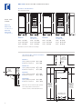
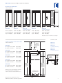
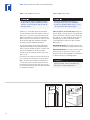
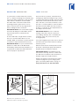
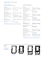
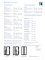
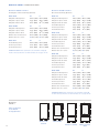
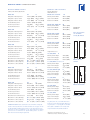
B U I LT - I N R E F R I G E R AT I O N
I NSTALLATION I NSTRUCTIONS
CONTENTS
Installation Recommendations
3
Installation Specifications
4
Installation Instructions
8
Framed Panel Installation
12
Overlay Panel Installation
16
Completing the Installation
20
Service Information
23
Specifications are subject to change without notice.
Check our website, subzero.com, for the most
up-to-date specifications.
As you follow these instructions, you will
notice WARNING and CAUTION symbols.
This blocked information is important for the
safe and efficient installation of Sub-Zero
equipment. There are two types of potential
hazards that may occur during installation.
signals a situation where minor injury or
product damage may occur if you do not
follow instructions.
states a hazard that may cause serious
injury or death if precautions are not
followed.
Another footnote we would like to identify is
IMPORTANT NOTE: This highlights information that is especially relevant to a problemfree installation.
SUB-ZERO ® is a registered trademark of Sub-Zero Freezer Company, Inc.
B U I LT- I N I N S TA L L A T I O N R E C O M M E N D A T I O N S
I N S TA L L AT I O N R E C O M M E N D AT I O N S
The importance of the installation of the
Sub-Zero Built-In unit cannot be overemphasized. Installation should be done by a
qualified installer.
Before you begin the installation process, it
is recommended that you read this entire
Installation Instructions book. There are key
details that you should take special care to
observe during the installation. By reading
these instructions carefully, you will make the
installation process easier, problem-free and,
most importantly, safe.
Any questions or problems about the
installation should be directed to your
Sub-Zero dealer or the Sub-Zero Customer
Service Department at 800-222-7820 or e-mail
[email protected]. You can also
visit our website at subzero.com.
T O O L S A N D M AT E R I A L S R E Q U I R E D
The following is a list of tools and materials
that should be available for proper installation.
Phillips screwdriver set
Slotted screwdriver set
Torx drive screwdriver set
4' (1.2 m) of 1/4" copper tubing and saddle
valve for the water line—part #4200880
(do not use self-piercing valves)
Copper tubing cutter
Level—2' (.6 m) and 4' (1.2 m) recommended
Appliance Dolly able to support 700 lbs
(317 kg) and adequate manpower to
handle the weight of the unit
Various sized pliers
Wrench set
Allen wrench set
5/16"
hex bolt nut driver
Crescent wrenches
Cordless drill and assorted drill bits
Masonite, plywood, 1/8" pressed fiberboard,
cardboard or other suitable material to
protect finished flooring
Appropriate materials to cover and protect
the home and its furnishings during installation
Dimensions in parentheses are in
millimeters unless otherwise specified.
3
B U I LT- I N I N S TA L L A T I O N S P E C I F I C A T I O N S
I N S TA L L AT I O N S P E C I F I C AT I O N S
Make sure that the actual equipment that was
shipped to you matches the design you are
expecting to install. The Sub-Zero Built-In line
offers the following design alternatives—
framed, overlay and stainless steel models.
Each of these design options has specific
installation requirements, which means it is
vital that the unit match your planning and
space needs. Before you begin the installation
process, check the exact model number you
need against the model number on the
shipping carton.
If the unit you receive does not match your
requirements, contact your Sub-Zero dealer.
S I T E P R E PA R AT I O N
Make sure that the finished rough opening
where the Built-In unit is to be installed is
properly prepared. Refer to the Overall Dimensions and Installation Specifications for your
specific model on the following pages. These
specifications are identical for each of the
design alternatives—whether your model is
framed, overlay or stainless steel. Make sure
that the rough opening dimensions, door
swing clearance, electrical service and
plumbing are correct for the model you are
about to install.
If you are installing Built-In units side by side,
a separating filler strip is recommended. Add
the filler strip width to the finished rough
opening dimension. Complete the installation
with the Anchoring Kit (part #4200900), see
page 21.
IMPORTANT NOTE: To operate properly, the
door must open a minimum of 90˚. Use a
minimum 3" (76) filler in corner installations to
assure a 90˚ door opening. Allow enough clearance in front of the unit for full door swing.
IMPORTANT NOTE: Make sure the floor under
the unit is level with the surrounding finished
floor.
4
B U I LT- I N I N S TA L L A T I O N S P E C I F I C A T I O N S
OVERALL DIMENSIONS
All Refrigerator | All Freezer Models
73"
73"
73"
(1854)
(1854)
(1854)
A L L R E F R I G E R AT O R
ALL FREEZER
Model 601R
All Refrigerator
Model 601RG
All Refrigerator
with Glass Door
36"
36"
36"
24"
(914)
(914)
(914)
(610)
Model 601R
Model 601RG
Model 601F
All Refrigerator
All Refrigerator
with Glass Door
All Freezer
Width
Width
Width
36" (914)
36" (914)
36" (914)
Height 73" (1854)
Height 73" (1854)
Height 73" (1854)
Depth
Depth
Depth
24" (610)
24" (610)
Model 601F
All Freezer
24" (610)
Illustrations shown in stainless steel design.
I N S TA L L A T I O N S P E C I F I C A T I O N S
All Refrigerator | All Freezer Models
EXTEND
WATER LINE
APPROX 36" (914)
FROM BACK WALL
(601F ONLY)
24"
(610)
ROUGH
OPENING
DEPTH
Models 601R and 601RG will not require the
water line connection.
SHUT-OFF
VALVE
Dimensions are for finished rough openings.
TOP VIEW
Door swing clearances are based on
stainless steel door and handle dimensions.
3/8"(10)
FRAME
EXTENSION
23 7/8"
(606)
BEHIND
FRAME
90˚
36 1/16"
(916)
351/2" (902)
ROUGH OPENING WIDTH
72 3/4" (1848)
ROUGH OPENING
HEIGHT TO
FINISHED
FLOORING
72 3/4" (1848)
MINIMUM HEIGHT
REQUIRED TO
FINISHED
FLOORING
(LEVELERS IN)
LOCATE ELECTRICAL
WITHIN ENTIRE SHADED AREA
LOCATE WATER SUPPLY
WITHIN BOTTOM SHADED
AREA ONLY (601F ONLY)
24"
6"
(610)
(152)
3"
11"
E
(76)
(279)
W
FRONT VIEW
Dimensions in parentheses are in
millimeters unless otherwise specified.
5
B U I LT- I N I N S TA L L A T I O N S P E C I F I C A T I O N S
OVERALL DIMENSIONS
Over-and-Under Models
OVER-ANDUNDER
84"
84"
84"
84"
(2134)
(2134)
(2134)
(2134)
Model 611
Model 611G
with Glass Door
Model 650
Model 650G
with Glass Door
30"
30"
36"
36"
24"
(762)
(762)
(914)
(914)
(610)
Model 611
Model 611G
Model 650
with Glass Door
Width
30" (762)
Width
30" (762)
Model 650G
with Glass Door
Width
36" (914)
Width
36" (914)
Height 84" (2138)
Height 84" (2138)
Height 84" (2138)
Height 84" (2138)
Depth
Depth
Depth
Depth
24" (610)
24" (610)
24" (610)
24" (610)
Illustrations shown in stainless steel design.
I N S TA L L A T I O N S P E C I F I C A T I O N S
Over-and-Under Models
24"
Model 611
A) Rough Opening Width
29 1/2" (749)
B) Min Door Clearance
30 1/8" (765)
EXTEND
WATER LINE
APPROX 36" (914)
FROM BACK WALL
(610)
ROUGH
OPENING
DEPTH
SHUT-OFF
VALVE
TOP VIEW
Model 611G
3/8"(10)
FRAME
EXTENSION
237/8"
(606)
BEHIND
FRAME
A) Rough Opening Width
29 1/2" (749)
B) Min Door Clearance
30 1/8" (765)
7"
6"
(152)
Model 650
A) Rough Opening Width
35 1/2" (902)
B) Min Door Clearance
36 1/16" (916)
LOCATE ELECTRICAL
WITHIN SHADED AREA
90˚
B
A
Model 650G
ROUGH OPENING WIDTH
A) Rough Opening Width
35 1/2" (902)
B) Min Door Clearance
36 1/16" (916)
Dimensions are for finished rough openings.
Door swing clearances are based on
stainless steel door and handle dimensions.
3
E
(178)
83" (2108)
MIN HEIGHT
REQUIRED TO
FINISHED
FLOORING
(LEVELERS IN)
751/2"
83 3/4" (2127)
ROUGH OPENING
HEIGHT TO
FINISHED
FLOORING WITH
STANDARD
11" (279) GRILLE
(1918)
LOCATE WATER SUPPLY
WITHIN SHADED AREA
3"
(76)
18"
6"
(457)
(152)
W
FRONT VIEW
6
B U I LT- I N I N S TA L L A T I O N S P E C I F I C A T I O N S
OVERALL DIMENSIONS
Side-by-Side Models
84"
(2134)
36"
42"
42"
48"
48"
24"
(914)
(1067)
(1067)
(1219)
(1219)
(610)
Model 661
Model 642
Model 685
Model 632
Model 695
Ice | Water Dispensing
Width
36" (914)
Width
42" (1067)
Width
Ice | Water Dispensing
42" (1067)
Width
48" (1219)
Width
48" (1219)
Height 84" (2138)
Height 84" (2138)
Height 84" (2138)
Height 84" (2138)
Height 84" (2138)
Depth
Depth
Depth
Depth
Depth
24" (610)
24" (610)
24" (610)
24" (610)
24" (610)
Illustrations shown in stainless steel design.
S I D E - B Y- S I D E
I N S TA L L A T I O N S P E C I F I C A T I O N S
Model 661
Side-by-Side Models
24"
(610)
ROUGH
OPENING
DEPTH
Model 661
A) Rough Opening Width
35 1/2" (902)
B) Min Door Clearance
20 3/4" (527)
EXTEND
WATER LINE
APPROX 36" (914)
FROM BACK WALL
Model 642
Model 685
Ice | Water Dispensing
SHUT-OFF
VALVE
Model 632
TOP VIEW
Model 695
Ice | Water Dispensing
Model 642
A) Rough Opening Width
41 1/2" (1054)
B) Min Door Clearance
25 9/16" (649)
7"
E
(178)
6"
(152)
Model 685
A) Rough Opening Width
41 1/2" (1054)
B) Min Door Clearance
25 9/16" (649)
LOCATE ELECTRICAL
WITHIN SHADED AREA
3/8"(10)
FRAME
EXTENSION
237/8"
(606)
BEHIND
FRAME
A
Model 632
ROUGH OPENING WIDTH
A) Rough Opening Width
47 1/2" (1207)
B) Min Door Clearance
29 1/4" (743)
Model 695
A) Rough Opening Width
47 1/2" (1207)
B) Min Door Clearance
29 1/4" (743)
90˚
83" (2108)
751/2"
83 3/4" (2127)
MIN HEIGHT
REQUIRED TO
FINISHED
FLOORING
(LEVELERS IN)
(1918)
ROUGH OPENING
HEIGHT TO
FINISHED
FLOORING WITH
STANDARD
11" (279) GRILLE
B
Dimensions are for finished rough openings.
Door swing clearances are based on
stainless steel door and handle dimensions.
LOCATE WATER SUPPLY
WITHIN SHADED AREA
3"
(76)
18"
6"
(457)
(152)
W
FRONT VIEW
Dimensions in parentheses are in
millimeters unless otherwise specified.
7
B U I LT- I N I N S TA L L A T I O N I N S T R U C T I O N S
ELECTRICAL R E Q U I R E M E N T S
PLUMBING R E Q U I R E M E N T S
A 115 V AC, 60 Hz, 15 amp circuit breaker and
electrical supply are required. A separate
circuit, servicing only this appliance, is
required.
For Built-In models with an automatic ice
maker, rough in the water supply line. Connect
a 1/4" OD copper line to the house supply. Use
an easily accessible shut-off valve between the
water supply and the unit. This valve is usually
placed about 6" (152) from the compression
fitting. Do not use self-piercing valves. A
saddle valve kit (part # 4200880) is available
from your Sub-Zero dealer.
All Sub-Zero Built-In models are equipped with
a power supply cord with a 3-prong grounding
plug, which must be plugged into a mating
3-prong grounding-type wall receptacle. Follow
the National Electrical Code and local codes
and ordinances when installing the receptacle.
For location of the electrical supply, refer to the
Installation Specifications illustration for your
specific model on pages 5–7.
IMPORTANT NOTE: A ground fault circuit
interrupter (GFCI) is not recommended and
may cause interruption of operation.
Do not use an extension cord or twoprong adapter. Electrical ground is
required on this appliance. Do not remove
the power supply cord ground prong.
The outlet must be checked by a qualified
electrician to be sure that it is wired with
the correct polarity. Verify that the outlet
provides 115 volts and is properly
grounded.
The water line should be routed up through
the floor within 1/2" (13) from the back wall and
no higher than 3" (76) off the floor. If the water
supply is brought in from behind the unit,
route the water line through the back wall, no
more than 3" (76) from the floor. Regardless of
the routing, allow 3' (1 m) of excess copper
tubing to remain outside the wall or floor for
easy connection to the unit. For location of the
water supply, refer to the Installation Specifications illustration for your specific model on
pages 5–7.
A line filter is required when water conditions
have a high sediment content. The ice maker
operates on water pressure of 20 psi (1.4 bar)
to 100 psi (6.9 bar).
A reverse osmosis system can be used,
provided there is a consistent water pressure
of 20 psi (1.4 bar) to 100 psi (6.9 bar) supplied
to the water valve at all times.
IMPORTANT NOTE: In some cases a reverse
osmosis water filter system may not be able to
maintain the minimum water pressure consistently.
Good water is important for high quality ice.
It is not recommended that the ice maker be
connected to a softened water supply. Water
softener chemicals, such as salt from a
malfunctioning softener, can damage the ice
maker mold and lead to poor ice quality. If a
softened water supply cannot be avoided, it is
important that the water softener be well maintained and operating properly.
8
Dimensions in parentheses are in
millimeters unless otherwise specified.
B U I LT- I N I N S TA L L A T I O N I N S T R U C T I O N S
U N PAC K T H E U N I T
GRILLE R E M O VA L
Uncrate the unit, remove its wood base and
discard the shipping bolts that hold the wood
base to the bottom of the unit. Remove all
packing materials and tape.
In order to prevent damage to the grille and to
access the power cord, the top grille assembly
should be removed prior to moving the unit.
IMPORTANT NOTE: Do not discard the
kickplate, anti-tip blocking kit and hardware.
These items will be needed for installation.
Retract the front leveling legs to allow you to
move the unit more easily during installation.
You will extend the leveling legs when the unit
is in its final position to reduce the possibility
of the unit tipping forward.
Remove the drain pan from the base of the
unit to avoid damage to the drain pan, and
allow for proper placement of the appliance
dolly.
Models 611, 611G, 650, 650G, 661, 642, 685,
632 and 695—framed and stainless steel:
Remove three counter-sunk grille screws at the
bottom of the grille and cut the red nylon
shipping strap. NOTE: Grille screws are
accessed with door(s) open. Then tilt the grille
forward and release the springs from behind
the grille. Refer to illustration 1 below.
Models 601R, 601RG and 601F—framed and
overlay: Remove the two black screws in the
lowest louver of the grille. Tilt the bottom of
the grille out and away. It will release from the
top of the grille. Refer to illustration 2 below.
Models 601R, 601RG and 601F—stainless
steel: The lower grille snaps out by pulling
forward on the bottom of the grille.
Keep door(s) and drawer taped closed
while moving unit.
Models 611, 611G, 650, 650G, 661, 642, 685,
632 and 695—overlay: First, remove the inner
grille panel assembly as shown in illustration 3
below. Lift up, then pull out at the bottom, pull
the top section down and out of the top key
slot. Remove the five mounting screws that
hold the outer grille panel assembly to the top
compartment. Refer to illustration 4.
Grille Springs
Grille
Screws
(inside door)
Illus. 1
Illus. 2
Illus. 3
Illus. 4
9
B U I LT- I N I N S TA L L A T I O N I N S T R U C T I O N S
ANTI-TIP B L O C K I N G K I T
POSITION T H E U N I T
To prevent the unit from tipping forward
and provide a stable installation, the unit
must be secured in place with an anti-tip
blocking device.
Protect any finished flooring before
moving the unit into place. All Built-In
models are equipped with rollers, so you
can easily move the unit into place.
If there is a solid soffit above the unit with
clearance between the unit and the soffit of 1"
(25) or less, you won't need to block the unit.
Refer to illustration 5 below. For installations
with clearances of more than 1" (25), you must
block the unit with the anti-tip blocking kit
(wood block and hardware) provided.
Shut off power to the wall outlet. Plug the
power supply cord into the 15 amp grounded
outlet and roll the unit into position under the
wood block or soffit. Using the front and rear
leveling legs, raise the unit until it makes
contact with the wood block. See Level the
Unit, page 11.
Locate and mark two wall studs against the
wall where the Built-in unit will be installed.
Then locate the proper height to clear the unit.
The space between the unit top and the
bottom of the wood block must not be more
than 1/4" (6).
IMPORTANT NOTE: If possible, keep door(s)
closed on the unit until it is properly anchored.
IMPORTANT NOTE: If for any reason the unit
has been laid on its back or side, you must
allow the unit to stand upright for a minimum
of 24 hours before connecting power.
Position the wood block over the unit and use
the screws and ‘L‘ brackets to lock it in place.
Make sure the screws extend a minimum of
7/8" (22) into each of the two wall studs. The
wood block must be positioned securely and
must extend at least 3" (76) over the unit. Refer
to illustration 6 below.
To reduce the possibility of the unit
tipping forward, the front leveling legs
must be in contact with the floor.
SOFFIT
WALL STUD
1" (25)
SCREW
WOOD BLOCK
SHROUD
Illus. 5
10
Illus. 6
3"
(76)
B U I LT- I N I N S TA L L A T I O N I N S T R U C T I O N S
WAT E R L I N E C O N N E C T I O N
LEVEL T H E U N I T
To connect the ice maker water line, remove
the 1/4" compression fitting from its plastic bag
and join the water supply line to the solenoid
valve. Refer to illustration 7 below. NOTE:
The water valve can be removed from the
mounting bracket to gain easier access to
water connection. Be sure to purge the line
before making the final connection.
Once the unit is in position, extend the front
leveling legs down by turning the legs counterclockwise and adjust the height. The rear height
adjustment can be made from the front of the
base. Turn the 5/16" hex bolt clockwise to raise
the unit or counterclockwise to lower it. Refer to
illustration 8 below. When the unit is leveled
properly, or squared off, door adjustments are
less likely to be necessary.
IMPORTANT NOTE: Turn on the water supply
and check all fittings for leaks. Make certain
the electrical harness is attached to the
solenoid.
In areas with water of high mineral content,
the use of an in-line water filter is recommended. Make sure the filter is positioned and
accessible for replacement when necessary.
IMPORTANT NOTE: Let your customer know
that the ice maker will not fill with water
immediately, and that the first few batches of
ice produced should be discarded. Allow 24
hours for proper ice production.
IMPORTANT NOTE: Be sure to reference
leveling of the unit to the floor and not to
surrounding cabinetry. This could affect the
operation of the unit, such as door(s) not
closing properly.
For proper alignment, place the level on the top
and side of the unit's main frame for leveling
reference points.
After the unit has been leveled, make sure the
drain pan is installed properly and install the
kickplate. Refer to illustration 9 below.
IMPORTANT NOTE: The kickplate must be
removed for servicing. The floor cannot interfere with removal. Refer to label mounted on
kickplate support for height clearance.
Replace the grille by reversing the procedure
outlined on page 9. If you’re using a panel
grille, see Overlay Grille Panels on page 17.
Turn power back on to the wall outlet.
ELECTRICAL
CONNECTION
SOLENOID
VALVE
REAR
ADJUSTMENT
FRONT
LEVELERS
Illus. 7
Illus. 8
Dimensions in parentheses are in
millimeters unless otherwise specified.
Illus. 9
11
F R A M E D PA N E L I N S TA L L A T I O N
FRAMED
PA N E L S
Refer to the
Framed Panel
Specifications on
pages 14–15 for
panel dimensions.
PA N E L I N S TA L L A T I O N
FRAMED PA N E L S
Before you begin installing panels, refer to the
Panel Specifications for framed or overlay
models and be sure you are working with the
panel design called for in your installation. If
your customer has chosen the stainless steel
design, the unit has been shipped complete
with a finished stainless steel look. It will not
be necessary to install panels or handle
hardware. In your final preparation for stainless steel units, use a stainless steel cleaner to
remove any marks. Abrasive cleaners should
not be used, as they may scratch the surface.
If your customer has chosen a framed design
application, make sure that the panels you are
about to install match dimensions listed in the
Framed Panel Specifications on pages 14–15.
If your customer has ordered either a framed
or overlay model, you will be installing panels
to give the unit the custom Sub-Zero look.
If the thickness of the custom panel is less
than a 1/4" (6), back it up with a sheet of shim
material to build the total thickness to a 1/4" (6).
If the panel is thicker than a 1/4" (6), rout an
edge around the panel to get a proper fit.
IMPORTANT NOTE: The weight of each panel
cannot exceed 50 lbs (23 kg).
IMPORTANT NOTE: On all Built-In models,
routing, recessing or optional extended
handles may be required on raised panels for
finger clearance under the handle. See Raised
Panels, page 13.
To install framed panels, the door handle(s)
must be removed. The handle screws are
hidden by a magnet backed trim molding.
Remove the molding using a piece of tape to
pull it away from the handle and expose the
handle screws. The molding will bend at the
center so that you can remove it. Refer to
illustration 10 below.
Illus. 10
12
Illus. 11
F R A M E D PA N E L I N S TA L L A T I O N
M O D E L S 6 8 5 A N D 6 9 5 FRAMED KITS
With a Phillips screwdriver, remove the
handles from the freezer and refrigerator
doors. Slide the panel into the frame on the
door. With the panel in position, replace the
handles. Be sure the panel is inserted
completely into the channel for proper fit and
alignment. Refer to illustration 11 on page 12.
PA RT I A L F R A M E D A C C E S S O RY K I T
Replace the trim molding by inserting the top,
then the bottom into the handle channel.
Release the middle and set the magnets.
If you choose not to use custom wood panels
above or below the glasswell for the Model
685 or 695 framed application, a stainless steel
insert panel will be provided with the partial
framed accessory kit. This accessory kit (part
# FRAMPAR), available through your Sub-Zero
dealer, includes molding and a stainless steel
insert panel for above and below the glasswell
on a framed unit.
R A I S E D PA N E L S
Detailed installation instructions are included
with the partial framed accessory kit.
You may have to rout, recess or use optional
extended handles with some door panel
designs to allow for finger clearance. This is
particularly true if your unit has raised panels
greater than 1/4" (6) total thickness.
IMPORTANT NOTE: The weight of each panel
cannot exceed 50 lbs (23 kg).
Check the location of offset when you’re using
specific routing for the grip area only. Refer to
the Built-In section of the Sub-Zero Design
Guide for a full-scale template of the standard
full-length handle and panel. Use this grid
template to lay out your panel design for
finger clearance when standard full-length
handles are used.
Dimensions in parentheses are in
millimeters unless otherwise specified.
PA N E L
DESIGN
Additional panel
design information
can be found in
the Sub-Zero
Design Guide.
Check our website
at subzero.com.
F R A M E D R E T R O F I T A C C E S S O RY K I T
With the framed retrofit accessory kit, existing
Model 680 or 690 door panels can be used on
a new Model 685 or 695 framed unit. This
accessory kit (part # FRAMRET), available
through your Sub-Zero dealer, includes
moldings and stainless steel insert panels to
accommodate existing Model 680 or 690
framed door panels.
Detailed installation instructions are included
with the framed retrofit accessory kit.
13
F R A M E D PA N E L S P E C I F I C A T I O N S
F R A M E D D O O R PA N E L S
F R A M E D D O O R PA N E L S
All Refrigerator | All Freezer Framed (F) Models
Over-and-Under Framed (F) Models
Model 601R
W
H
Model 611
W
H
Refrigerator Framed Panel
34 1/8" (867)
58 15/16" (1497)
Refrigerator Framed Panel
28 1/8" (714)
48 1/16" (1221)
Freezer Framed Panel
28 1/8"
18 3/8" (467)
Raised Panel Handle Recess Location –
Refrigerator Panel
A) 29 15/32" (749)
Model 601RG
W
H
Refrigerator Framed Panel
34 1/8" (867)
58 15/16" (1497)
Raised Panel Handle Recess Location –
Raised Panel Handle Recess Location –
A) 29 15/32" (749)
Refrigerator Panel
Window Cut-out Dimensions
25 3/8" (645)
41 3/16" (1046)
Window Cut-out Location
C) 4 3/8" (111)
D) 13 3/8" (340)
Model 601F
W
H
Freezer Framed Panel
34 1/8"
58 15/16"
(867)
(714)
Refrigerator Panel
A) 24 1/32" (610)
Freezer Panel
B) 14 1/16" (357)
Model 611G
W
Refrigerator Framed Panel
28 1/8" (714)
48 1/16" (1221)
Freezer Framed Panel
28 1/8" (714)
18 3/8" (467)
H
Raised Panel Handle Recess Location –
(1497)
Raised Panel Handle Recess Location –
Refrigerator Panel
A) 24 1/32" (610)
Freezer Panel
B) 14 1/16" (357)
Window Cut-out Dimensions
19 3/8" (492)
39 5/16" (999)
4 3/ 8"
D) 4 3/8" (111)
Window Cut-out Location
C)
(111)
A) 29 15/32" (749)
Freezer Panel
IMPORTANT NOTE: Panel specifications are for Built-In framed (F)
models. Panel specifications for overlay models are on pages 18–19.
Model 650
W
H
Refrigerator Framed Panel
34 1/8" (867)
48 1/16" (1221)
Freezer Framed Panel
34 1/8"
18 3/8" (467)
(867)
Raised Panel Handle Recess Location –
Refrigerator Panel
A) 24 1/32" (610)
Freezer Panel
B) 17 1/16" (433)
Model 650G
W
H
Refrigerator Framed Panel
34 1/8" (867)
48 1/16" (1221)
Freezer Framed Panel
34 1/8"
18 3/8" (467)
(867)
Raised Panel Handle Recess Location –
Refrigerator Panel
A) 24 1/32" (610)
Freezer Panel
B) 17 1/16" (433)
Window Cut-out Dimensions
25 3/8" (645)
39 5/16" (999)
Window Cut-out Location
C) 4 3/8" (111)
D) 4 3/8" (111)
C
IMPORTANT NOTE: Panel specifications are for Built-In framed (F)
models. Panel specifications for overlay models are on pages 18–19.
FRAMED
PA N E L S
C
C
C
C
C
14"(356)
Panel specifications
are for Built-In
framed (F) models.
14"(356)
14"(356)
H
C
14"(356)
H
A
A
A
A
H
H
D
D
B
14
W
W
Models 601R
and 601F
Model 601RG
H
W
Models 611 and 650
B
H
W
Models 611G and 650G
F R A M E D PA N E L S P E C I F I C A T I O N S
F R A M E D D O O R PA N E L S
PA RT I A L F R A M E D D O O R PA N E L S
Side-by-Side Framed (F) Models
Ice | Water Dispensing Framed (F) Models
Model 661
W
H
Model 685
W
H
Refrigerator Framed Panel
19 1/8" (486)
67 11/16" (1719)
Refrigerator Partial Framed Panel
15 5/8" (397)
67 11/16" (1719)
Freezer Framed Panel
14 5/8"
67 11/16"
Freezer Partial Framed Panel
15 5/8"
67 11/16" (1719)
(371)
(1719)
(397)
Raised Panel Handle Recess Location –
A) 38 5/32" (969)
Refrigerator | Freezer Panel
Model 642
W
H
Refrigerator Framed Panel
24" (610)
67 11/16" (1719)
Freezer Framed Panel
15 5/8" (397)
67 11/16" (1719)
A) 38 5/32" (969)
Model 685
W
H
Refrigerator Framed Panel
24" (610)
67 11/16" (1719)
Freezer Framed Panel
15 5/8" (397)
67 11/16" (1719)
W
17 15/16" (456) 67 11/16" (1719)
H
Freezer Partial Framed Panel
17 15/16" (456) 67 11/16" (1719)
The partial framed accessory kit (FRAMPAR) is required for this option.
Kit includes partial framed molding and classic stainless steel inset
handle panels for above and below glasswell on the refrigerator door.
Raised Panel Handle Recess Location –
Refrigerator | Freezer Panel
Model 695
Refrigerator Partial Framed Panel
PA N E L G R I L L E O P T I O N
Framed (F) Models
Raised Panel Handle Recess Location –
38 5/32"
Refrigerator | Freezer Panel
A)
Glasswell Cut-out Dimensions
5 7/ 8"
Glasswell Location (Refrigerator)
E)
(969)
(150)
1 9/16"
(39)
12 7/16"
F)
(315)
28 9/16"
(726)
Model 632
W
Refrigerator Framed Panel
27 11/16" (703) 67 11/16" (1719)
H
Freezer Framed Panel
17 15/16" (456) 67 11/16" (1719)
Raised Panel Handle Recess Location –
A) 38 5/32" (969)
Refrigerator | Freezer Panel
H
Models 611 and 611G
W
Grille Panel Width
28 3/16" (716)
Models 650, 650G, 661
W
Grille Panel Width
34 3/16" (868)
Models 642 and 685
W
Grille Panel Width
40 3/16" (1021)
Models 632 and 695
W
Grille Panel Width
46 3/16" (1173)
10" (254) Grille
H
Grille Panel Height
8 15/16" (227)
11" (279) Grille (standard)
H
Grille Panel Height
9 15/16" (252)
Model 695
W
Refrigerator Framed Panel
27 11/16" (703) 67 11/16" (1719)
12" (305) Grille Height
H
Freezer Framed Panel
17 15/16" (456) 67 11/16" (1719)
Grille Panel Height
10 15/16" (278)
Raised Panel Handle Recess Location –
13" (330) Grille
H
Refrigerator | Freezer Panel
A) 38 5/32" (969)
Grille Panel Height
11 15/16" (303)
Glasswell Cut-out Dimensions
5 7/8" (150)
12 7/16" (315)
14" (356) Grille
H
Glasswell Location (Refrigerator)
E) 1 9/16" (39)
F) 28 9/16" (726)
Grille Panel Height
12 15/16" (329)
15" (381) Grille
H
IMPORTANT NOTE: Panel specifications are for Built-In framed (F)
models. Panel specifications for overlay models are on pages 18–19.
Grille Panel Height
13 15/16" (354)
For Models 685 and 695, panel thickness in the glasswell area can
range from 1/4" (6) to a maximum of 1 1/8" (29). If the panel is thicker,
you must rout out a minimum 1/4" (6) flat landing area to accommodate the bezel surrounding the glasswell.
For panel grille insert size, use width dimension listed
for your model and height dimension for grille option.
11" (279) grille is standard.
FRAMED
PA N E L S
E
H
H
H
14" (356)
F
A
W
Panel specifications
are for Built-In
framed (F) models.
W
Models 661, 642
and 632
W
W
Models 685 and 695
W
W
Models 685 and 695
Partial Framed Option
Dimensions in parentheses are in
millimeters unless otherwise specified.
15
OV E R L AY PA N E L I N S T A L L A T I O N
OV E R L AY P A N E L S
If your customer has chosen an overlay design
application, make sure that the panels you are
about to install match dimensions listed in the
Overlay Panel Specifications on pages 18–19.
O V E R L AY
PA N E L S
Refer to the
Overlay Panel
Specifications on
pages 18–19 for
panel dimensions.
IMPORTANT NOTE: The weight of each panel
assembly cannot exceed 50 lbs (23 kg).
Illustration 12 below is a cross section view of
the three panel assembly showing placement
of the door / drawer / grille trim. Illustration 13
shows a rear view of the three panel assembly
and critical dimensions, standard for all
models.
IMPORTANT NOTE: The size of the overlay
panel is critical. It must fit over the door frame.
Overlay models are shipped without handle
hardware. The cabinet manufacturer or
designer will provide handle hardware at the
job site to match the overall decorating
scheme.
Install the handle hardware before inserting
the panel. We recommend larger D-style pulls.
The use of small, one-piece knobs is not
recommended. If you use screws with thick
heads, you will need to countersink the screws
into the backer panel before sliding the
assembly into place.
To install overlay panels, first remove the
magnet backed trim molding using a piece of
tape to pull it away from the frame and expose
the screws. The molding will bend at the
center so that you can remove it. Remove the
frame by removing the four screws. The door
channel is now ready to accept the overlay
panel assembly.
Slide the panel into the frame on the door.
With the panel in position, replace the frame
end. Be sure the panel is inserted completely
into the channel for proper fit and alignment.
Sub-Zero allows a 1/4" (6) space to slide the
backing material into place in the frame. If
your material is thicker than a 1/4" (6), either
rout an edge around the panel to get a proper
fit or mount the decorative overlay panel on a
sheet of 1/4" (6) thick material and insert the
backing material into the channel.
Replace the trim molding by inserting the top,
then the bottom into the handle channel.
Release the middle and set the magnets.
You must allow for 0.10" (3) space between the
backer board and the decorative panel, so the
panel will slide easily into the door frame.
Spacer Panel
Overlay Panel
Spacer Panel
.10"
(3)
Overlay Panel
1/4" (6) Backer
5/16" (8) min
5/32" (4)
1/16" (2)
Illus. 12
16
Panel
Door/Drawer/
Grille Trim
Backer
Panel
~3/4"
(19)
Illus. 13
.10"
(3) 1/4" (6)
OV E R L AY PA N E L I N S TA L L A T I O N
M O D E L S 6 8 5 A N D 6 9 5 GLASSWELL
OV E R L AY G R I L L E P A N E L S
The dispenser area of Models 685 and 695 has
been engineered to enable the use of the
overlay panel application. Installing overlay
panels for these models is the same procedure
as for other Built-In models. The refrigerator
door panel will need to accommodate a cut-out
for the glasswell bezel.
Models 611, 611G, 650, 650G, 661, 642, 685,
632 and 695: Remove the inner grille panel
assembly as described in Grille Removal,
page 9. Remove the top two corner screws and
pull away the top frame. Slide the panel into
position in the grille frame. If you are using a
grille panel 1/4" (6) or thinner, you will need to
install a filler.
To remove the glasswell bezel for an overlay
Model 685 or 695, the water grille and touch
pad must be removed. Lift the water grille up
and out. Next, remove the touch pad assembly
which is taped in place, by removing the
center plastic mandrel supports. Carefully tilt
the touch pad out and disconnect the wire
harness (blue side up) from the back side of
the touch pad. Remove the bezel by removing
the four screws.
Insert the overlay panel into the door trim.
Reverse the procedure to install the bezel,
touch pad and water grille. To install the plastic
rivets, insert rivets through the touch pad and
into the control housing and secure by
pressing mandrels into the body of the rivets.
Refer to illustrations 14 and 15 below.
Reattach the top frame by reinstalling the
two top corner screws. Install the inner grille
panel assembly onto the unit, by reversing the
procedure outlined in Grille Removal, page 9.
Refer to specifications for Overlay Grille Panels
on page 19, and illustration 13 on page 16, for
the exact sizing of all three panels.
PA N E L
DESIGN
Additional panel
design information
can be found in
the Sub-Zero
Design Guide.
Check our website
at subzero.com.
Do not exceed the panel dimensions
listed for the appropriate overlay grille
panel you are specifying. The overlay
decorative panel cannot be any larger or
it may restrict the air flow to the
compressor area and cause problems with
the operation of the Sub-Zero unit.
IMPORTANT NOTE: The total panel thickness
(including backer and spacer, if used) in the
glasswell bezel area can range from 1/4" (6) to a
maximum of 1 1/8" (29). If the panel is thicker,
provisions must be made to rout out a space
to accommodate the bezel surrounding the
glasswell.
Ice
Key Pad
Water
Key Pad
Lock
Indicator
Touch Pad
Light
Key Pad
Water
Grille
Glasswell
Bezel
Illus. 14
Illus. 15
Dimensions in parentheses are in
millimeters unless otherwise specified.
17
OV E R L AY PA N E L S P E C I F I C A T I O N S
O V E R L AY D O O R P A N E L S
O V E R L AY D O O R P A N E L S
All Refrigerator | All Freezer Overlay (O) Models
Over-and-Under Overlay (O) Models
Model 601R
W
H
Model 611
W
H
Refrigerator Overlay Panel
34 7/16" (875)
59 1/4" (1505)
Refrigerator Overlay Panel
28 7/16" (722)
48 7/8" (1241)
Refrigerator Spacer Panel
33 1/2"
58 5/16"
Refrigerator Spacer Panel
27 1/2"
(699)
47 7/16" (1205)
Refrigerator Backer Panel
34 1/8" (867)
58 15/16" (1497)
Refrigerator Backer Panel
28 1/8" (714)
48 1/16" (1221)
Freezer Overlay Panel
28 7/16" (722)
18 11/16" (475)
Model 601RG
W
H
Freezer Spacer Panel
27 1/2" (699)
17 3/4" (451)
Refrigerator Overlay Panel
34 7/16" (875)
59 1/4" (1505)
Freezer Backer Panel
28 1/8" (714)
18 3/8" (467)
Refrigerator Spacer Panel
33 1/2" (851)
58 5/16" (1481)
Refrigerator Backer Panel
34 1/8" (867)
58 15/16" (1497)
Model 611G
W
H
Window Cut-out Dimensions
25 7/16" (646)
41 1/4" (1048)
Refrigerator Overlay Panel
28 7/16" (722)
48 7/8" (1241)
Window Cut-out Location
C) 4 1/2" (114)
D) 13 1/2" (343)
Refrigerator Spacer Panel
27 1/2" (699)
47 7/16" (1205)
Refrigerator Backer Panel
28 1/8" (714)
48 1/16" (1221)
Model 601F
W
H
Freezer Overlay Panel
28 7/16" (722)
18 11/16" (475)
Freezer Overlay Panel
34 7/16" (875)
59 1/4" (1505)
Freezer Spacer Panel
27 1/2" (699)
17 3/4" (451)
Freezer Spacer Panel
33 1/2" (851)
58 5/16" (1481)
Freezer Backer Panel
28 1/8" (714)
18 3/8" (467)
Freezer Backer Panel
34 1/8" (867)
58 15/16" (1497)
Window Cut-out Dimensions
19 7/16" (494)
39 3/8" (1000)
(851)
(1481)
IMPORTANT NOTE: Panel specifications are for Built-In overlay (O)
models. Panel specifications for framed models are on pages 14– 15.
Window Cut-out Location
C)
4 1/ 2"
(114)
D) 5" (127)
Model 650
W
H
Refrigerator Overlay Panel
34 7/16" (875)
48 7/8" (1241)
Refrigerator Spacer Panel
33 1/2"
(851)
47 7/16" (1205)
Refrigerator Backer Panel
34 1/8"
(867)
48 1/16" (1221)
Freezer Overlay Panel
34 7/16" (875)
18 11/16" (475)
Freezer Spacer Panel
33 1/2"
(851)
17 3/4" (451)
Freezer Backer Panel
34 1/8"
(867)
18 3/8" (467)
Model 650G
W
H
Refrigerator Overlay Panel
34 7/16" (875)
48 7/8" (1241)
Refrigerator Spacer Panel
33 1/2"
(851)
47 7/16" (1205)
Refrigerator Backer Panel
34 1/8"
(867)
48 1/16" (1221)
Freezer Overlay Panel
34 7/16" (875)
18 11/16" (475)
Freezer Spacer Panel
33 1/2" (851)
17 3/4" (451)
Freezer Backer Panel
34 1/8" (867)
18 3/8" (467)
Window Cut-out Dimensions
25 7/16" (646)
39 3/8" (1000)
Window Cut-out Location
C) 4 1/2" (114)
D) 5" (127)
IMPORTANT NOTE: Panel specifications are for Built-In overlay (O)
models. Panel specifications for framed models are on pages 14– 15.
O V E R L AY
PA N E L S
C
C
Panel specifications
are for Built-In
overlay (O) models.
C
C
C
C
H
H
H
H
D
D
18
W
W
Models 601R
and 601F
Model 601RG
H
W
Models 611 and 650
H
W
Models 611G and
650G
OV E R L AY PA N E L S P E C I F I C A T I O N S
O V E R L AY D O O R P A N E L S
O V E R L AY G R I L L E P A N E L S
Side-by-Side Overlay (O) Models
Overlay (O) Models
Width Dimensions
Model 661
W
H
Models 611 and 611G
Refrigerator Overlay Panel
19 7/16" (494)
68" (1727)
Overlay Panel Width
28 7/16" (722)
Refrigerator Spacer Panel
18 1/2" (470)
67 1/16" (1703)
Spacer Panel Width
27 1/2" (699)
Refrigerator Backer Panel
19 1/8"
67 11/16"
Backer Panel Width
28 1/8" (714)
Freezer Overlay Panel
14 15/16" (379) 68" (1727)
Freezer Spacer Panel
14" (356)
67 1/16" (1703)
Models 650, 650G, 661
W
Freezer Backer Panel
14 5/8"
67 11/16"
Overlay Panel Width
34 7/16" (875)
Spacer Panel Width
33 1/2" (851)
Backer Panel Width
34 1/8"
Models 642 and 685
W
Overlay Panel Width
40 7/16"
Spacer Panel Width
39 1/2" (1003)
Backer Panel Width
40 1/8" (1019)
Models 632 and 695
W
Overlay Panel Width
46 7/16" (1180)
Spacer Panel Width
45 1/2" (1156)
Backer Panel Width
46 1/8" (1172)
(486)
(371)
(1719)
(1719)
Model 642
W
H
Refrigerator Overlay Panel
24 5/16" (618)
68" (1727)
Refrigerator Spacer Panel
23 3/8" (594)
67 1/16" (1703)
Refrigerator Backer Panel
24" (610)
67 11/16" (1719)
Freezer Overlay Panel
15 15/16" (405) 68" (1727)
Freezer Spacer Panel
15" (381)
67 1/16" (1703)
Freezer Backer Panel
15 5/8" (397)
67 11/16" (1719)
Model 685
Refrigerator Overlay Panel
W
H
24 5/16" (618)
68" (1727)
W
(867)
(1027)
Refrigerator Spacer Panel
23 3/8" (594)
67 1/16" (1703)
Refrigerator Backer Panel
24" (610)
67 11/16" (1719)
Freezer Overlay Panel
15 15/16" (405) 68" (1727)
Freezer Spacer Panel
15" (381)
67 1/16" (1703)
10" (254) Grille
Freezer Backer Panel
15 5/8"
67 11/16"
Overlay Panel Height
9 1/4" (235)
Spacer Panel Height
8 5/16" (211)
Backer Panel Height
8 15/16" (227)
O V E R L AY
PA N E L S
Panel specifications
are for Built-In
overlay (O) models.
H
Height Dimensions
(397)
(1719)
12 7/16" (315)
H
Glasswell Cut-out Dimensions
5 7/8" (150)
Glasswell Location (Overlay)
E) 1 11/16" (43) F) 28 3/4" (730)
Glasswell Location (Spacer)
E) 1 1/4" (31)
F) 28 1/4" (718)
11" (279) Grille (standard)
H
Glasswell Location (Backer)
E) 1 9/16" (39)
F) 28 9/16" (726)
Overlay Panel Height
10 1/4" (260)
Spacer Panel Height
9 5/16" (237)
9 15/16" (252)
Model 632
W
H
Backer Panel Height
Refrigerator Overlay Panel
28" (711)
68" (1727)
12" (305) Grille Height
H
Refrigerator Spacer Panel
27 1/16" (687)
67 1/16" (1703)
Overlay Panel Height
11 1/4" (286)
Refrigerator Backer Panel
27 11/16" (703) 67 11/16" (1719)
Spacer Panel Height
10 5/16"
Freezer Overlay Panel
18 1/4" (464)
68" (1727)
Backer Panel Height
10 15/16" (278)
Freezer Spacer Panel
17 5/16"
67 1/16"
13" (330) Grille
H
Freezer Backer Panel
17 15/16"
Overlay Panel Height
12 1/4" (311)
Spacer Panel Height
11 5/16" (287)
Model 695
W
H
Backer Panel Height
11 15/16" (303)
Refrigerator Overlay Panel
28" (711)
68" (1727)
Refrigerator Spacer Panel
27 1/16" (687)
67 1/16" (1703)
14" (356) Grille
H
Overlay Panel Height
13 1/4"
Spacer Panel Height
12 5/16" (313)
Backer Panel Height
12 15/16" (329)
15" (381) Grille
H
Overlay Panel Height
14 1/4" (362)
Spacer Panel Height
13 5/16" (338)
Backer Panel Height
13 15/16" (354)
Refrigerator Backer Panel
(440)
(456)
(1703)
67 11/16"
(1719)
27 11/16" (703) 67 11/16" (1719)
Freezer Overlay Panel
18 1/4" (464)
68" (1727)
Freezer Spacer Panel
17 5/16" (440)
67 1/16" (1703)
Freezer Backer Panel
17 15/16" (456) 67 11/16" (1719)
Glasswell Cut-out Dimensions
5 7/8" (150)
Glasswell Location (Overlay)
E) 1 11/16" (43) F) 28 3/4" (730)
12 7/16" (315)
Glasswell Location (Spacer)
E) 1 1/4" (31)
F) 28 1/4" (718)
Glasswell Location (Backer)
E) 1 9/16" (39)
F) 28 9/16" (726)
IMPORTANT NOTE: Panel specifications are for Built-In overlay (O)
models. Panel specifications for framed models are on pages 14– 15.
For Models 685 and 695, panel thickness in the glasswell area can
range from 1/4" (6) to a maximum of 1 1/8" (29). If the panel is thicker,
you must rout out a minimum 1/4" (6) flat landing area to accommodate the bezel surrounding the glasswell.
W
W
Models 661, 642
and 632
E
H
(262)
F
W
W
Models 685 and 695
(337)
H
W
Overlay grille panel
For grille panel size, use width dimensions
listed for your model and height dimensions
for grille option. 11" (279) grille is standard.
Panel grille is available for all overlay units
except Models 601R, 601RG and 601F.
Dimensions in parentheses are in
millimeters unless otherwise specified.
19
C O M P L E T I N G T H E I N S TA L L AT I O N
S I D E PA N E L I N S TA L L A T I O N
If you’re installing a Built-In model with side
panels, check with your installer or use one of
the following Side Panel Installation Options.
Drill three holes equidistant in a vertical
section of the aluminum frame, and install pan
head screws. Do not drill through model and
serial number plate. Anchor the side panel
with decorative screws or finishing nails from
a local hardware store. Do not use adhesives.
Refer to illustration 16 below.
The dimensions given in the Side Panel
Installation Options are for typical wood side
panels. If a 1/4" (6) thick or less panel is used
and inserted into the return channel extrusion,
then a 24 1/4" (616) wide panel is necessary. In
this application, the panel must be notched for
the grille and other brackets or screws that are
in the return channel. Toe kick cut-outs will be
necessary for all side panel applications. Refer
to illustration 17 below.
IMPORTANT NOTE: The use of side panels
may change the width of your rough opening.
IMPORTANT NOTE: The overall height on the
side panel will vary with the height of the grille
being used. Make sure you know your finished
height before cutting any panels.
S I D E PA N E L I N S TA L L AT I O N O P T I O N S
1/4" (6) THICK SIDE PANEL FITTED IN TO UNIT FRAME
DOOR
PAN HEAD SCREW
1/8" (3) THICK BATTENS
SIDE OF SUB-ZERO UNIT
FRAME
1/4" (6) SIDE PANEL MATERIAL
241/4" (616)
1/4" (6) THICK SIDE PANEL FITTED UP TO UNIT FRAME
DOOR
PAN HEAD SCREW
1/8" (3) THICK BACK-UP
1/4" (6)
THICK BATTENS
SIDE OF SUB-ZERO UNIT
FRAME
1/4" (6) SIDE PANEL MATERIAL
24" (610)
3/8" (10) THICK SIDE PANEL FITTED UP TO UNIT FRAME
DOOR
PAN HEAD SCREW
1/8" (3) THICK BATTENS
SIDE OF SUB-ZERO UNIT
FRAME
3/8" (10) SIDE PANEL MATERIAL
24" (610)
1/2" (13) THICK SIDE PANEL FITTED UP TO UNIT FRAME
DOOR
PAN HEAD SCREW
FRAME 1/8" (3) ROUT
SIDE OF SUB-ZERO UNIT
13 1/4" (337)
DOOR
11/8"
21/2" (64)
PAN HEAD
SCREW
1/2" (13) SIDE PANEL MATERIAL
24" (610)
1/4" (6)
(29)
METAL SIDE PANEL FITTED UP TO UNIT FRAME
DOOR
FRAME
PAN HEAD SCREW
SIDE OF SUB-ZERO UNIT
SIDE PANEL
FRAME
METAL SIDE PANEL MATERIAL
24" (610)
Illus. 16
1/4" (6)
3" (76)
3" (76)
Illus. 17
20
Top Views
4" (102)
Dimensions in parentheses are in
millimeters unless otherwise specified.
W
C O M P L E T I N G T H E I N S TA L L A T I O N
ANCHOR T H E U N I T
After door and side panels have been installed,
the unit has been leveled and door adjustment
completed, anchor the unit to the opening.
This will assure a proper fit and a secure
installation. The Sub-Zero Anchoring Kit (part
#4200900), available from your Sub-Zero
dealer, includes the necessary hardware.
IMPORTANT NOTE: Be sure to level and
square the unit before anchoring it.
T WO U N I T S A N C H O R E D TO G E T H E R
Drill three 13/64" holes through the middle
trim of both units.
Using the Loctite on the screws, install the
three Chicago screw posts.
Recheck the units for level.
Drill three 3/16" holes through both outer
trims. Refer to illustration 18 below.
Using a 1/8" drill bit, drill into the cabinetry
for a pilot hole.
Install all six Sems to the cabinetry.
U N I T A N C H O R E D T O C A B I N E T RY
First, make sure units have been leveled
and aligned, and doors adjusted.
Drill three 3/16" holes through both outer
trims. Refer to illustration 19 below.
Drill a 1/8" pilot hole into the cabinetry.
Install all six Sems.
HINGE A D J U S T M E N T
Check to make sure the doors are properly
aligned. If not, the door hinges will have to be
adjusted. Remove the two small shipping
screws from the top and bottom hinge as
shown in illustrations 20 and 21 below. Next,
using a 1/8" allen head wrench, loosen the allen
head screws in the top and bottom hinge.
Loosen the allen head screws only slightly, so
that the door will remain in position as you
adjust it. You will now be able to move the
door to the left, right, or in and out. Once the
adjustments are made, tighten the allen head
screws—do not put the shipping screws back.
Do not drill through the model and serial
number plate.
17 1/8" (435)
17 1/8" (435)
17 1/8" (435)
17 1/8" (435)
17 1/8" (435)
17 1/8" (435)
17 1/8"
(435)
17 1/8"
(435)
Illus. 18
Illus. 20
Illus. 21
Illus. 19
21
C O M P L E T I N G T H E I N S TA L L AT I O N
9 0 D E G R E E D O O R S TO P
I N S TA L L AT I O N C H E C K L I S T
The doors of all Built-In models open to 130
degrees. For Models 601R, 601RG, 601F, 661,
642, 685, 632 and 695, optional 90˚ or 105˚ door
stop kits are available through your Sub-Zero
dealer.
The importance of the installation of the
Sub-Zero Built-In unit cannot be overemphasized. Proper installation is the responsibility
of the selling dealer or installer.
Models 611, 611G, 650 and 650G come with
a door stop pin to limit the door swing to 90
degrees. To install the door stop pin for
Models 611 and 650, remove the pin from the
plastic package located behind the grille and
insert it into the space provided on the top
hinge plate. Tighten with a screwdriver. Refer
to illustration 22 below.
For Models 611G and 650G, remove the
door stop pin from the plastic package located
behind the grille and insert it into the space
provided on the lower hinge plate. Tighten
with a screwdriver. Refer to illustration 23.
Illus. 22
22
Dimensions in parentheses are in
millimeters unless otherwise specified.
IMPORTANT NOTE: To ensure a safe and
proper installation, the following checklist
should be completed by the installer to ensure
that no part of the installation has been overlooked.
Any questions or problems about the installation should be directed to your Sub-Zero
dealer or the Sub-Zero Customer Service
Department at 800-222-7820 or e-mail
[email protected]. You can also
visit our website at subzero.com.
Illus. 23
S E RV I C E I N F O R M A T I O N
S E RV I C E I N F O R M A T I O N
I N S TA L L A T I O N C H E C K L I S T
Has the unit been secured in place with the
provided anti-tip blocking kit or is there
clearance of 1" (25) or less between the unit
and a solid soffit?
Are both front leveling legs extended down
to make contact with the floor? Is the unit
level?
Is the power cord plugged into a properly
grounded 3-prong outlet, which has been
installed in accordance with all applicable
electrical codes?
If you need service, be sure to have the model
and serial number when you call. You’ll find
these numbers on the model and serial
number on the plate at the top frame of the
unit inside the door.
Contact a Sub-Zero Factory Authorized Service
Center, a Sub-Zero dealer, or the Sub-Zero
Customer Service Department, P. O. Box 44130,
Madison, WI 53744-4130, call 800-222-7820 or
e-mail [email protected].
Is the water supply connected for units with
an automatic ice maker? Have you checked
for leaks?
Is the drain pan in the proper position? Has
the kickplate been installed properly?
C O N TA C T
I N F O R M AT I O N
Sub-Zero
Customer Service:
800-222-7820
Website:
subzero.com
If you are storing or disposing of your old
refrigerator or freezer, please do it safely.
Remove the doors or tightly secure the
doors closed. Child entrapment accidents
can be tragic.
E-mail Address:
customerservice@
subzero.com
Are panels attached securely and properly
aligned?
Have the door(s) been aligned for proper
appearance and operation?
Have all accessories been installed?
Have any installation / service problems
been noted on the product registration
card? Has the registration card been
mailed in?
Have stainless steel door(s) been inspected
for any imperfections? This is to be done
by the dealer / installer with the customer
upon completion of the installation.
NOTE: Classic, platinum and carbon stainless steel panels are covered by a limited
60-day parts and labor warranty for
cosmetic defects.
The information and images in this book are the
copyright property of Sub-Zero Freezer Company, Inc.
Neither this book nor any information or images
contained herein may be copied or used in whole or
in part without the express written permission of
Sub-Zero Freezer Company, Inc.
©Sub-Zero Freezer Company, Inc. all rights reserved.
23
S U B - Z E R O F R E E Z E R C O M PA N Y, I N C .
3758610
5/ 2005
P. O . B O X 4 4 1 3 0
MADISON, WI 53744-4130
800-222-7820
S U B Z E RO. C O M