1
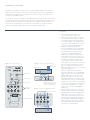
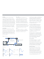
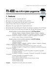
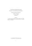
Owner’s Manual
Seismix 3 and Seismix 5
Congratulations on choosing Krix
The Seismix 3 and Seismix 5 active subwoofers will complement existing Stereo or Home
Theatre systems producing an increase in low frequency performance for a deep experience.
The Seismix 3 and Seismix 5 are compatible with a variety of small to large sized, sealed
or vented, main/satellite speakers.
Your subwoofer contains an amplifier of the highest electronic standards. Krix have introduced
In Circuit Serial Programming (ICSP), meaning the microcontroller within the amplifier can be
upgraded via the serial interface located internally on the amplifier module. This means as
future features are developed your subwoofer can be upgraded. You would simply need
to return the amplifier module to Krix, where the upgrade would take place.
connection
Figure 1 Back panel of subwoofer
Figure 2 Connection using Line Level signal
To main
stereo speakers
Main AV Receiver
Volume Control
From pre-out
or sub-out
+--+
Low Pass Control
Line Level Inputs
Speaker Level
Input/Outputs
If only a single or mono sub-out
exists, then plug that into the left
Line Level input labelled mono
Figure 3 Connection using Speaker Level signal
To main stereo speakers
Mains Power Switch
Main Stereo Amplifier
+--+
1. Ensure the main power switch is off
and connect the mains power cord.
2. There are two methods which you can use
to connect the Seismix subwoofer, either
via the line level inputs which will require
your stereo amplifier / AV receiver to have
a subwoofer output facility (mono or stereo
outputs) or via the speaker level inputs.
Method 1: Line Level Connections
It is recommended that you use Line Level
connections for home theatre applications.
Connect the SUB OUT socket(s) on your
AV receiver to the Line Level input(s)
which are a pair of RCA sockets located
in the middle of the rear subwoofer panel
(see figure 1). The SUB OUT socket on your
AV receiver is usually mono which can be
connected to the Seismix with one lead
to the ‘Left (mono)’ input. If your AV receiver
has stereo SUB OUT sockets then use dual
leads, connecting these to the ‘Left and
Right’ inputs. Refer to figure 2 for connection
using Line Level signal.
Method 2: Speaker Level Connections
For stereo applications connect the Speaker
Level outputs on your main amplifier to the
Speaker Level inputs on the rear panel of
the Seismix (see figure 1). Then connect
the Speaker Level outputs on the rear panel
of the Seismix to each of your left and right
speakers. Be sure to maintain correct phasing
for each set of speaker leads, red (positive +)
to (+) and black (negative -) to (-). Refer
to figure 3 for connection using Speaker
Level signal.
3. Before turning the Seismix on, ensure the
volume control is turned down and set the
Low Pass (Hz) control to the middle position
(see figure 1). Turn on the unit with the
power switch located at the bottom of the
rear panel, the subwoofer will activate and
the blue Power / Standby LED will light up.
Begin by playing music with bass content
and slowly increase the volume dial on the
subwoofer to a moderate level.
features
Automatic on / off circuit
Standby Mode
Symetrix Vent
Clipping protection
-Opto-compressor with fast attack
to prevent overload
- Soft limiting to prevent amplifier clipping
Multi-layered fault protection
- DC Detect Sensor
- Thermal Sensor
- Mains Fuse
Electronic filtering
- Earth lift switch to eliminate ground loops
-2nd order low pass filter adjustable
from 60Hz to 150Hz
- Adjustable Hi / Lo gain setting
- 0°/180° phase switch
-Fixed 2nd order high pass filter to
reduce driver excursion below 30Hz
Independent adjustable gain control
Heavy duty, high efficiency long throw
paper cone drivers designed for high level
sound reinforcement
High current low noise amplifier
Automatic On / Off Circuit
For the auto circuit function to operate, the
power switch on the back of the subwoofer
needs to be left on (and can be done so safely,
see figure 1). The Auto Circuit monitors both
the speaker level or line level inputs and powers
the amplifier in the subwoofer. When a signal
is present the blue Power / Standby LED at
the top of the rear panel will remain lit. When
a signal is not present, the power will remain
on for approximately 15 minutes and will then
automatically switch itself to standby mode.
In standby mode the blue Power / Standby
LED will flash.
Warning: it is recommended that the unit is turned off at the mains power if being left unattended for any extended periods.
Standby Mode
Krix have included an energy saving device
when the unit is in Standby mode, meaning
the Seismix draws a meagre 3 watts (costing
approximately AUD$5.00 for 1 year to run).
Symetrix Vent
The Seismix subwoofer enclosure features
Symetrix bass reflex venting, with the vent
exhibiting the same flare radius both internally
and externally. This lowers subwoofer distortion
and serves to reduce vent turbulence or
“chuffing” at high drive levels.
Clipping Protection
There are several layers of protection in
the electronics of the Seismix to prevent
clipping damage.
Opto-compressor: When faced with a signal
peak which is in excess of what the Seismix
can accurately reproduce, a compressor circuit
activates to reduce the level of the signal once
it passes the preset threshold. This permits the
Seismix to perform at high level with only a
mild reduction in the signal’s dynamic content.
Soft Limiter: If severe overdriving of the
amplifier continues to place a strain on the
compressor circuit, a soft limiting circuit
activates. The soft limiter circuit monitors
the Seismix’s amplifier power supply voltage
and prevents a direct current (DC) signal from
reaching the bass driver, causing damage.
Fault Protection
The mains fuse protects against any
major electrical faults or short circuits
and incorporates an inrush current limiter
to eliminate power surges when using the
main on / off switch. The Seismix uses an
ATMEL MEGA16® microcontroller which is
the integrated circuit responsible for the
advanced fault protection features of the
Seismix amplifier. A microcontroller is a small
single chip computer optimised for hardware
control that runs a program stored in flash
memory on the chip. The construction of
the Seismix amplifier utilises surface mount
technology (SMT), which results in a more
compact design, high resistance to mechanical
vibration and higher circuit performance. The
filter capacitor bank present in the Seismix
amplifier features many low Equivalent Series
Resistance (ESR) capacitors allowing lower
supply impedance and greater instantaneous
power delivery to the loudspeaker load.
DC Detect Sensor: Clipping is severe square
wave distortion that contains a direct
current (DC) component often responsible
for loudspeaker damage. In the event of an
abnormal function the amplifier will not only
shut down, but all LED’s will flash. If this
happens turn the subwoofer off and contact
your nearest Krix retailer for further assistance.
Thermal Sensor: The Seismix has a generously
sized heat sink, permitting normal operation
in high ambient temperatures. A thermal
sensor internally connected to the heat
sink is monitored every 20 seconds by the
microcontroller. In the unlikely event that
the amplifier’s temperature reaches above
65 degrees celsius the microcontroller
will reduce output by 1dB every 20 seconds
until the temperature is 65 degrees celsius
or below. The microcontroller will return
the amplifier to normal operating settings
by increasing the output by 1dB every
20 seconds.
Earth Lift
Hi / Lo Gain
The Earth Lift button ensures the Seismix
can be connected to a wide range of stereo
amplifiers / AV receivers. Should a humming
noise be evident when the Seismix is connected,
push the Earth Lift button (see figure 1) which
interrupts the current that may be circulating from
the subwoofer’s signal ground through the mains
earth wiring (see figure 4). Note: The Earth Lift
button does not break the mains earth connection
to the subwoofer, only the connection between
the subwoofer’s signal ground and the mains
earth. To guard against electric shock NEVER
disconnect the mains earth from any appliance.
The Hi / Lo Gain button (see figure 1) is
positioned below the blue Power / Standby
LED, this button allows you to increase or
decrease the sensitivity of the subwoofer
without adjusting other settings. In the ’Lo’
gain position, a much higher input signal is
required, and you will need to increase the
main volume control to reach maximum output.
Low Pass (Hz)
The Low Pass control (see figure 1) adjusts
the total bass content from the Seismix. This
control allows you to adjust the upper limit of the
Seismix’s frequency range between 60 –150 Hz.
The higher the selection, the broader the range
of bass information heard. This setting can be
adjusted for personal taste and integration with
your main speakers.
In the ’Hi’ gain position the output of the
subwoofer is increased by approximately 20dB,
requiring a lower input signal, meaning you will
not need to increase the main volume control
to achieve the same amount of output.
Phase
Signal phase can be left at '0°', or shifted
180° (inverted), by pressing the Phase button
(see figure 1). This applies to the output of
the subwoofer compared to its input.
Figure 4 Earth lift button
Mains power outlets
To get the most from all of your speakers they
must be operating in Phase. That is the signals
must all be positive going or negative going
simultaneously. If this is not the case and one
signal is positive going and the other is negative
going the result will be a cancellation of signal
and the sound at those particular frequencies
will be perceived as quite 'empty' sounding
and lacking potential impact.
The setting of the Phase button (ie. 0° or
180°) and the resulting sound is dependant
on where the subwoofer is positioned in
relation to the main speakers. The best way
to find the correct setting is through trial and
error during set up by comparative listening
tests. In most cases the effect will be subtle
and there won't be a complete lack of bass.
If no difference can be heard, the position
of the button is not crucial.
The effect of phase can best be shown with
the representation of a sine wave (see figure
5). The effect shown in the lower diagram is
with the signals 'out of phase' and this can be
rectified by changing the position of the Phase
button. This will invert the negative going
signal and the result will be the same as
the first, 'In Phase', example.
Line Level Inputs
Denotes chassis Earth
Denotes signal ground
Circulating ground currents
Earth lift button
Signal connection
Subwoofer
Receiver / Amplifier
Figure 5 Phase
2
2
1
1
0
+
-1
-2
0
Positive going
-2
2
1
1
-1
-2
=
In Phase
=
-1
2
0
2
+
0
-1
-2
1
0
-1
-2
Negative going
2
1
=
180° out
of phase
=
0
-1
-2
(No output)
Line level inputs (see figure 1 or 2) need to
be connected to the ‘PRE OUT’ or 'SUB OUT’
from your stereo amplifier / AV receiver.
The line level stereo input performs a summing
function adding the left and right signals where
applicable, to give a mono (L+R) signal. This
mono signal is filtered and then amplified
before being sent to the subwoofer driver.
Speaker Level Inputs
The speaker level stereo inputs combine
the signal going to the main left and right
speakers providing a mono (L+R) signal to
the subwoofer driver. This mono signal is
filtered and then amplified in the same
way as the line level input signal before being
sent to the loudspeaker. Two pairs of terminals
are provided so that the speaker level signals
can “pass through” the subwoofer on the way
to the main speakers (see figure 1 or 3).
trouble shooting
Volume
The volume control will adjust the volume
of the subwoofer only. The control can be
set for the subtleties of the lower octaves
in musical performances or increased for
the earth shattering explosions and effects
on movie sound tracks. The volume control
on your main amplifier / AV receiver controls
volume for your overall system (see figure 1).
positioning
The procedure for setting up any subwoofer
can be time consuming, requiring numerous
minor adjustments to get the desired result.
There is no definitive 'correct' way to set up a
subwoofer. Given different listening environments
different people’s tastes and different speakers,
there are a number of variables that have to be
taken into consideration.
It is up to the individual listener to adjust
the Seismix for the character and strength
of bass that is preferred for whatever type
of source material is being reproduced.
It is beneficial to select music that is familiar
to you when carrying out listening tests and
setting up procedures and as a suggestion
play recordings that use wooden instruments
such as acoustic guitars, oboes, cello etc.
These instruments exhibit a strong resonant
characteristic in the low to mid bass region
and will highlight unpleasant ‘woody’ or ‘chesty’
sound qualities suggesting there is too much
overlap in the bass information between the
subwoofer and main speakers.
To fine tune the integration of the Seismix into
your Hi-fi system, start with both the Low Pass
(Hz) and Volume at the middle setting. Gradually
adjust the setting of the Low Pass (Hz) either
up or down (see figure 1). This will vary the
amount of overlap from the sub to the main
speakers and increase or decrease the level at
those frequencies. The effect is a strengthening
or weakening of the upper bass region. You might
reach a point where the sound develops a 'boxy'
or 'chesty' quality which is not desirable. This
could indicate there is too much overlap from
the sub to the main speakers and is remedied
by turning the Low Pass (Hz) back. Adjust the
Volume level to suit your personal taste.
Symptom
Probable Cause
Treatment
No noise from the
subwoofer when
main power is on
uto switch circuit has not
A
operated due to no signal
Play source material and
gradually increase the volume
from the main Hi-fi amplifier
Volume turned down
Increase Volume on the sub
Signal has no bass content
lay source material with
P
sufficient bass content
Apart from the source
material having little bass
content, the settings on the
sub may need adjustment
Increase setting of the
Low Pass (Hz) control
Very little bass coming
from the subwoofer
Try changing position of
the Phase button
Increase Volume on the sub
hange gain button from
C
‘Lo’ to ‘Hi’
Bass content is
too strong and
uncomfortable
to listen to
Settings on the subwoofer
may need adjustment
Subwoofer emits
a humming sound
Current may be circulating
from the subwoofer’s signal
ground through the mains
earth wiring.
Decrease the setting of
the Low Pass (Hz) control
ecrease the Volume on
D
the subwoofer
ctivate the Earth Lift by
A
pushing the button which
will break the current loop
If you have any queries regarding the Seismix, the set up procedure or any other KRIX
product, please contact your nearest Krix retailer or Krix direct. Contact details are on
the back cover of this booklet.
warranty
5 years warranty applies to the cabinet and speaker
1 year warranty applies to the amplifier and related internal electronics
(Refer to the details on the warranty card supplied)
Seismix 3: specifications
Drivers
Bass Driver
Nominal 255mm (10”) diameter paper cone driver developed for high level, low frequency reinforcement
Electronics
Amplifier Power
200 watts RMS into the nominal 4 ohm driver
Maximum instantaneous power 400 watts
Amplifier S/N
>70dB
Distortion - Input to Speaker <0.1% - @ 80 watts RMS
Line Level Inputs
Left Input (mono)
Lo – 900mV RMS for maximum output
Hi – 100mV RMS
Left + Right Input (stereo) Lo – 450mV RMS for maximum output
Hi – 50mV RMS
General
Frequency Range
Output
Auto Power On / Off
Phase Select
22Hz - 150Hz (-6dB) in room response
120dB maximum SPL in room response
15 minute delay before switching to standby after no input signal
0° or 180° (relative to input signal)
Cabinet
Enclosure Type
Dimensions
Material
Finish
Weight
Bass reflex, front vented
415mm high x 360mm wide x 390mm deep
17mm MDF
Vinyl or lacquered timber veneer
18kg
Due to continued development specifications may change without notice
Seismix 5: specifications
Drivers
Bass Driver
Nominal 305mm (12”) diameter paper cone driver developed for
high level, low frequency reinforcement and large linear cone travel
Electronics
Amplifier Power
Amplifier S/N
Distortion - Input to Speaker
Line Level Inputs
400 watts RMS into the nominal 4 ohm driver
Maximum instantaneous power 800 watts
>70dB
<0.1% - @ 80 watts RMS
Left Input (mono)
Lo – 900mV RMS for maximum output
Hi – 100mV RMS
Left + Right Input (stereo) Lo – 450mV RMS for maximum output
Hi – 50mV RMS
General
Frequency Range
Output
Auto Power On / Off
Phase Select
16Hz - 150Hz (-6dB) in room response
122dB maximum SPL in room response
15 minute delay before switching to standby after no input signal
0° or 180° (relative to input signal)
Cabinet
Enclosure Type
Dimensions
Material
Finish
Weight
Bass reflex, front vented
460mm high x 395mm wide x 440mm deep
19mm and 25mm MDF
Vinyl or lacquered timber veneer
30kg
Due to continued development specifications may change without notice
Krix Loudspeakers Pty Ltd
14 Chapman Road
Hackham SA 5163
Australia
T 61 8 8384 3433
F 61 8 8384 3419
[email protected]
krix.com