1
NWA1100-N
802.11b/g/n PoE Access Point
Version 1.00
Edition 3, 10/2013
Quick Start Guide
User’s Guide
Default Login Details
LAN IP Address
http://192.168.1.2
User Name
www.zyxel.com
Password
admin
1234
Copyright © 2013 ZyXEL Communications Corporation
IMPORTANT!
READ CAREFULLY BEFORE USE.
KEEP THIS GUIDE FOR FUTURE REFERENCE.
Screenshots and graphics in this book may differ slightly from your product due to differences in
your product firmware or your computer operating system. Every effort has been made to ensure
that the information in this manual is accurate.
Related Documentation
• Quick Start Guide
The Quick Start Guide shows how to connect the NWA and access the Web Configurator.
2
NWA1100-N User’s Guide
Contents Overview
Contents Overview
User’s Guide .........................................................................................................................................9
Introducing the NWA ............................................................................................................................... 11
Introducing the Web Configurator ...........................................................................................................20
Status Screens ........................................................................................................................................23
Tutorial ....................................................................................................................................................27
Technical Reference ..........................................................................................................................46
Wireless Settings Screen ........................................................................................................................48
Multi SSID Screen ...................................................................................................................................66
Wireless Security Screen ........................................................................................................................71
RADIUS Screen ......................................................................................................................................84
MAC Filter Screen ...................................................................................................................................87
IP Screen ................................................................................................................................................90
System Screens ......................................................................................................................................94
Remote Management ............................................................................................................................100
Certificate Screen .................................................................................................................................. 110
Log Screens .......................................................................................................................................... 114
Maintenance .......................................................................................................................................... 119
Troubleshooting ....................................................................................................................................126
NBG5715 User’s Guide
3
Table of Contents
Table of Contents
Contents Overview ..............................................................................................................................3
Table of Contents .................................................................................................................................4
Part I: User’s Guide ........................................................................................... 9
Chapter 1
Introducing the NWA .......................................................................................................................... 11
1.1 Introducing the NWA ......................................................................................................................... 11
1.2 Applications for the NWA .................................................................................................................. 11
1.2.1 Access Point ............................................................................................................................12
1.2.2 Bridge / Repeater ....................................................................................................................12
1.2.3 AP + Bridge .............................................................................................................................14
1.2.4 Wireless Client .........................................................................................................................15
1.2.5 Multi SSID ................................................................................................................................16
1.3 Ways to Manage the NWA ................................................................................................................16
1.4 Configuring Your NWA’s Security Features .......................................................................................17
1.4.1 Control Access to Your Device ................................................................................................17
1.4.2 Wireless Security .....................................................................................................................17
1.5 Good Habits for Managing the NWA .................................................................................................18
1.6 Hardware Connections ......................................................................................................................18
1.7 LEDs .................................................................................................................................................18
Chapter 2
Introducing the Web Configurator ....................................................................................................20
2.1 Accessing the Web Configurator .......................................................................................................20
2.2 Resetting the NWA ............................................................................................................................20
2.2.1 Methods of Restoring Factory-Defaults ...................................................................................21
2.3 Navigating the Web Configurator ......................................................................................................21
Chapter 3
Status Screens ....................................................................................................................................23
3.1 The Status Screen .............................................................................................................................23
3.1.1 System Statistics Screen .........................................................................................................25
Chapter 4
Tutorial .................................................................................................................................................27
4.1 How to Configure the Wireless LAN ..................................................................................................27
4
NWA1100-N User’s Guide
Table of Contents
4.1.1 Choosing the Wireless Mode ...................................................................................................27
4.1.2 Wireless LAN Configuration Overview ....................................................................................27
4.1.3 Further Reading .......................................................................................................................28
4.2 How to Configure Multiple Wireless Networks ..................................................................................29
4.2.1 Configure the SSID Profiles .....................................................................................................30
4.2.2 Configure the Standard Network .............................................................................................32
4.2.3 Configure the VoIP Network ....................................................................................................34
4.2.4 Configure the Guest Network ..................................................................................................35
4.2.5 Testing the Wireless Networks ................................................................................................37
4.3 NWA Setup in AP and Wireless Client Modes ..................................................................................38
4.3.1 Scenario ..................................................................................................................................38
4.3.2 Configuring the NWA in Access Point Mode ...........................................................................38
4.3.3 Configuring the NWA in Wireless Client Mode ........................................................................41
4.3.4 MAC Filter Setup .....................................................................................................................44
4.3.5 Testing the Connection and Troubleshooting ..........................................................................44
Part II: Technical Reference............................................................................ 46
Chapter 5
Wireless Settings Screen ...................................................................................................................48
5.1 Overview ...........................................................................................................................................48
5.2 What You Can Do in this Chapter .....................................................................................................48
5.3 What You Need To Know ..................................................................................................................49
5.4 Wireless Settings Screen ..................................................................................................................50
5.4.1 Access Point Mode ..................................................................................................................51
5.4.2 Bridge / Repeater Mode ..........................................................................................................53
5.4.3 AP + Bridge Mode ...................................................................................................................58
5.4.4 Wireless Client Mode ...............................................................................................................59
5.4.5 Multi SSID Mode ......................................................................................................................61
5.5 Technical Reference ..........................................................................................................................64
5.5.1 WMM QoS ...............................................................................................................................64
5.5.2 Additional Wireless Terms .......................................................................................................65
Chapter 6
Multi SSID Screen ...............................................................................................................................66
6.1 Overview ...........................................................................................................................................66
6.1.1 What You Can Do in this Chapter ............................................................................................66
6.1.2 What You Need To Know .........................................................................................................66
6.2 The Multi SSID Screen ......................................................................................................................67
6.2.1 Configuring SSID .....................................................................................................................68
6.3 Technical Reference ..........................................................................................................................69
NWA1100-N User’s Guide
5
Table of Contents
6.3.1 WMM QoS ...............................................................................................................................69
6.3.2 Type Of Service (ToS) .............................................................................................................70
Chapter 7
Wireless Security Screen ...................................................................................................................71
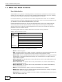
7.1 Overview ...........................................................................................................................................71
7.2 What You Can Do in this Chapter .....................................................................................................71
7.3 What You Need To Know ..................................................................................................................72
7.4 The Security Screen ..........................................................................................................................73
7.4.1 Security: WEP .........................................................................................................................75
7.4.2 Security: 802.1x Only ..............................................................................................................76
7.4.3 Security: 802.1x + Static WEP .................................................................................................78
7.4.4 Security: WPA, WPA2 or WPA2-MIX .......................................................................................80
7.4.5 Security: WPA-PSK, WPA2-PSK, WPA2-PSK-MIX .................................................................83
7.5 Technical Reference ..........................................................................................................................83
Chapter 8
RADIUS Screen ...................................................................................................................................84
8.1 Overview ...........................................................................................................................................84
8.2 What You Can Do in this Chapter .....................................................................................................84
8.3 What You Need to Know ...................................................................................................................84
8.4 The RADIUS Screen .........................................................................................................................85
Chapter 9
MAC Filter Screen...............................................................................................................................87
9.1 Overview ...........................................................................................................................................87
9.2 What You Can Do in this Chapter .....................................................................................................87
9.3 What You Need To Know ..................................................................................................................87
9.4 MAC Filter Screen .............................................................................................................................88
Chapter 10
IP Screen .............................................................................................................................................90
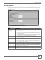
10.1 Overview .........................................................................................................................................90
10.2 What You Can Do in this Chapter ...................................................................................................90
10.3 What You Need to Know .................................................................................................................90
10.4 IP Screen ........................................................................................................................................91
10.5 Technical Reference ........................................................................................................................92
10.5.1 WAN IP Address Assignment ................................................................................................92
10.5.2 Spanning Tree Protocol (STP) ...............................................................................................92
Chapter 11
System Screens ..................................................................................................................................94
11.1 Overview .........................................................................................................................................94
6
NWA1100-N User’s Guide
Table of Contents
11.2 What You Can Do in this Chapter ....................................................................................................94
11.3 What You Need To Know .................................................................................................................94
11.4 General Screen ...............................................................................................................................96
11.4.1 Password Screen ...................................................................................................................97
11.5 Time Screen ...................................................................................................................................98
11.6 Technical Reference ........................................................................................................................99
11.6.1 Pre-defined NTP Time Servers List .......................................................................................99
Chapter 12
Remote Management........................................................................................................................100
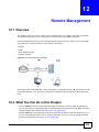
12.1 Overview .......................................................................................................................................100
12.2 What You Can Do in this Chapter .................................................................................................100
12.3 What You Need To Know ..............................................................................................................101
12.4 The Telnet Screen .........................................................................................................................103
12.5 The FTP Screen ............................................................................................................................104
12.6 The WWW Screen ........................................................................................................................104
12.7 The SNMP Screen ........................................................................................................................106
12.8 Technical Reference ......................................................................................................................108
12.8.1 MIB ......................................................................................................................................108
12.8.2 Supported MIBs ...................................................................................................................108
12.8.3 SNMP Traps ........................................................................................................................109
Chapter 13
Certificate Screen ............................................................................................................................. 110
13.1 Overview ....................................................................................................................................... 110
13.2 What You Can Do in this Chapter ................................................................................................. 110
13.3 What You Need To Know .............................................................................................................. 110
13.4 Certificates Screen ........................................................................................................................ 111
13.5 Technical Reference ...................................................................................................................... 111
13.5.1 Private-Public Certificates ................................................................................................... 111
13.5.2 Certification Authorities ........................................................................................................ 112
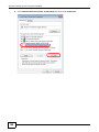
13.5.3 Checking the Fingerprint of a Certificate on Your Computer ............................................... 112
Chapter 14
Log Screens ...................................................................................................................................... 114
14.1 Overview ....................................................................................................................................... 114
14.2 What You Can Do in this Chapter ................................................................................................. 114
14.3 What You Need To Know .............................................................................................................. 115
14.4 View Log Screen ........................................................................................................................... 115
14.5 Log Settings Screen ...................................................................................................................... 116
Chapter 15
Maintenance ...................................................................................................................................... 119
NWA1100-N User’s Guide
7
Table of Contents
15.1 Overview ....................................................................................................................................... 119
15.2 What You Can Do in this Chapter ................................................................................................. 119
15.3 What You Need To Know .............................................................................................................. 119
15.4 Client Information Screen .............................................................................................................. 119
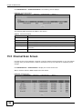
15.5 Channel Scan Screen ...................................................................................................................120
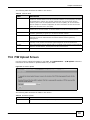
15.6 F/W Upload Screen .......................................................................................................................121
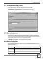
15.7 Configuration File Screen ..............................................................................................................123
15.7.1 Backup Configuration ..........................................................................................................123
15.7.2 Restore Configuration ..........................................................................................................123
15.7.3 Back to Factory Defaults .....................................................................................................125
15.8 Reboot Screen ..............................................................................................................................125
Chapter 16
Troubleshooting................................................................................................................................126
16.1 Power, Hardware Connections, and LEDs ....................................................................................126
16.2 NWA Access and Login ................................................................................................................127
16.3 Internet Access .............................................................................................................................128
16.4 Wireless LAN ................................................................................................................................129
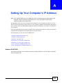
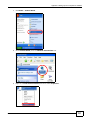
Appendix A Setting Up Your Computer’s IP Address ......................................................................130
Appendix B Pop-up Windows, JavaScript and Java Permissions ...................................................158
Appendix C IP Addresses and Subnetting.......................................................................................169
Appendix D Wireless LANs..............................................................................................................177
Appendix E Text File Based Auto Configuration ..............................................................................191
Appendix F Open Software Announcements...................................................................................193
Appendix G Customer Support........................................................................................................223
Appendix H Legal Information .........................................................................................................229
Index ..................................................................................................................................................235
8
NWA1100-N User’s Guide
P ART I
User’s Guide
9
10
C HAPT ER
1
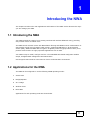
Introducing the NWA
This chapter introduces the main applications and features of the NWA. It also discusses the ways
you can manage your NWA.
1.1 Introducing the NWA
Your NWA extends the range of your existing wired network without additional wiring, providing
easy network access to mobile users.
The NWA controls network access with MAC address filtering and RADIUS server authentication. It
also provides a high level of network traffic security, supporting IEEE 802.1x, Wi-Fi Protected
Access (WPA), WPA2 and WEP data encryption. Its Quality of Service (QoS) features allow you to
prioritize time-sensitive or highly important applications such as VoIP.
Your NWA is easy to install, configure and use. The embedded Web-based configurator enables
simple, straightforward management and maintenance.
See the Quick Start Guide for instructions on how to make hardware connections.
1.2 Applications for the NWA
The NWA can be configured to use the following WLAN operating modes:
1
Access Point
2
Bridge/Repeater
3
AP + Bridge
4
Wireless Client
5
Multi SSID
Applications for each operating mode are shown below.
NWA1100-N User’s Guide
11
Chapter 1 Introducing the NWA
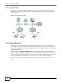
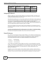
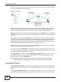
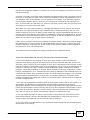
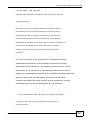
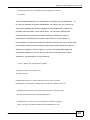
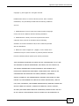
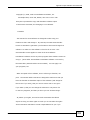
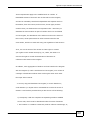
1.2.1 Access Point
The NWA is an ideal access solution for wireless Internet connection. A typical Internet access
application for your NWA is shown as follows. Stations A, B and C can access the wired network
through the NWAs.
Figure 1 Access Point Application
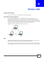
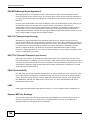
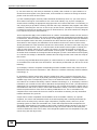
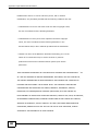
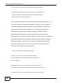
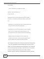
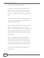
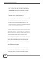
1.2.2 Bridge / Repeater
The NWA can act as a wireless network bridge and establish wireless links with other APs. In the
figure below, the two NWAs (A and B) are connected to independent wired networks and have a
bridge connection (A can communicate with B) at the same time. A NWA in repeater mode (C) has
no Ethernet connection.
When the NWA is in Bridge / Repeater mode, security between APs (the Wireless Distribution
System or WDS) is independent of the security between the wireless stations and the AP. If you do
not enable WDS security, traffic between APs is not encrypted. When WDS security is enabled, both
APs must use the same pre-shared key. See Section 5.4.2 on page 53 for more details.
Once the security settings of peer sides match one another, the connection between devices is
made.
12
NWA1100-N User’s Guide
Chapter 1 Introducing the NWA
At the time of writing, WDS security is compatible with other ZyXEL NWA-series access points only.
Refer to your other access point’s documentation for details.
Figure 2 Bridge Application
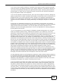
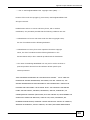
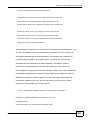
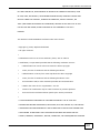
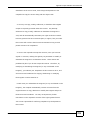
Figure 3 Repeater Application
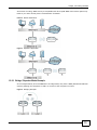
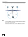
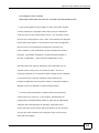
1.2.2.1 Bridge / Repeater Mode Example
In the example below, when both NWAs are in bridge mode, they form a WDS (Wireless Distribution
System) allowing the computers in LAN 1 to connect to the computers in LAN 2.
Figure 4 Bridging Example
NWA1100-N User’s Guide
13
Chapter 1 Introducing the NWA
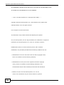
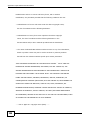
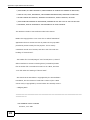
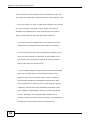
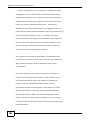
Be careful to avoid bridge loops when you enable bridging in the NWA. Bridge loops cause
broadcast traffic to circle the network endlessly, resulting in possible throughput degradation and
disruption of communications. The following examples show two network topologies that can lead
to this problem:
• If two or more NWAs (in bridge mode) are connected to the same hub.
Figure 5 Bridge Loop: Two Bridges Connected to Hub
• If your NWA (in bridge mode) is connected to a wired LAN while communicating with another
wireless bridge that is also connected to the same wired LAN.
Figure 6 Bridge Loop: Bridge Connected to Wired LAN
To prevent bridge loops, ensure that your NWA is not set to bridge mode while connected to both
wired and wireless segments of the same LAN.
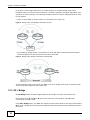
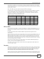
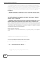
1.2.3 AP + Bridge
In AP+Bridge mode, the NWA supports both AP and bridge connection at the same time.
In the figure below, A and B use X as an AP to access the wired network, while X and Y
communicate in bridge mode.
Using AP + Bridge mode, your NWA can extend the range of the WLAN. In the figure below, A and
B act as AP + Bridge devices that forward traffic between associated wireless workstations and the
wired LAN.
14
NWA1100-N User’s Guide
Chapter 1 Introducing the NWA
When the NWA is in AP+Bridge mode, security between APs (the Wireless Distribution System or
WDS) is independent of the security between the wireless stations and the AP. If you do not enable
WDS security, traffic between APs is not encrypted. When WDS security is enabled, both APs must
use the same pre-shared key. See Section 5.4.3 on page 58 for more details.
Unless specified, the term “security settings” refers to the traffic between the wireless stations and
the NWA.
Figure 7 AP + Bridge Application
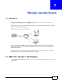
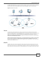
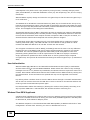
1.2.4 Wireless Client
The NWA can be used as a wireless client to communicate with an existing network. In the figure
below, the printer can receive requests from the wired computer clients A and B via the NWA in
Wireless Client mode.
Figure 8 Wireless Client Application
NWA1100-N User’s Guide
15
Chapter 1 Introducing the NWA
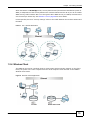
1.2.5 Multi SSID
A Basic Service Set (BSS) is the set of devices forming a single wireless network (usually an access
point and one or more wireless clients). The Service Set IDentifier (SSID) is the name of a BSS. In
Multi SSID mode, the NWA provides multiple virtual APs, each forming its own BSS and using its
own individual SSID profile.
You can configure up to eight SSID profiles, and have up to four active at any one time.
You can assign different wireless and security settings to each SSID profile. This allows you to
compartmentalize groups of users, set varying access privileges, and prioritize network traffic to
and from certain BSSs.
To the wireless clients in the network, each SSID appears to be a different access point. As in any
wireless network, clients can associate only with the SSIDs for which they have the correct security
settings.
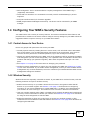
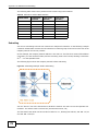
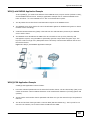
For example, you might want to set up a wireless network in your office where Internet telephony
(VoIP) users have priority. You also want a regular wireless network for standard users, as well as a
‘guest’ wireless network for visitors. In the following figure, VoIP_SSID users have QoS priority,
SSID01 is the wireless network for standard users, and Guest_SSID is the wireless network for
guest users.
Figure 9 Multiple BSSs
1.3 Ways to Manage the NWA
Use any of the following methods to manage the NWA.
16
NWA1100-N User’s Guide
Chapter 1 Introducing the NWA
• Web Configurator. This is recommended for everyday management of the NWA using a
(supported) web browser.
• Command Line Interface. Line commands are mostly used for troubleshooting by service
engineers.
• FTP (File Transfer Protocol) for firmware upgrades.
• SNMP (Simple Network Management Protocol). The device can be monitored by an SNMP
manager.
1.4 Configuring Your NWA’s Security Features
Your NWA comes with a variety of security features. This section summarizes these features and
provides links to sections in the User’s Guide to configure security settings on your NWA. Follow the
suggestions below to improve security on your NWA and network.
1.4.1 Control Access to Your Device
Ensure only people with permission can access your NWA.
• Control physical access by locating devices in secure areas, such as locked rooms. Most NWAs
have a reset button. If an unauthorized person has access to the reset button, they can then
reset the device’s password to its default password, log in and reconfigure its settings.
• Change any default passwords on the NWA, such as the password used for accessing the NWA’s
web configurator (if it has a web configurator). Use a password with a combination of letters and
numbers and change your password regularly. Write down the password and put it in a safe
place.
• See Chapter 11 on page 94 for instructions on changing your password.
• Configure remote management to control who can manage your NWA. See Chapter 12 on page
100 for more information. If you enable remote management, ensure you have enabled remote
management only on the IP addresses, services or interfaces you intended and that other remote
management settings are disabled.
1.4.2 Wireless Security
Wireless devices are especially vulnerable to attack. If your NWA has a wireless function, take the
following measures to improve wireless security.
• Enable wireless security on your NWA. Choose the most secure encryption method that all
devices on your network support. See Section 7.4 on page 73 for directions on configuring
encryption. If you have a RADIUS server, enable IEEE 802.1x or WPA(2) user identification on
your network so users must log in. This method is more common in business environments.
• Hide your wireless network name (SSID). The SSID can be regularly broadcast and unauthorized
users may use this information to access your network. See Section 6.2 on page 67 for directions
on using the web configurator to hide the SSID.
• Enable the MAC filter to allow only trusted users to access your wireless network or deny
unwanted users access based on their MAC address. See Section 9.4 on page 88 for directions on
configuring the MAC filter.
NWA1100-N User’s Guide
17
Chapter 1 Introducing the NWA
1.5 Good Habits for Managing the NWA
Do the following things regularly to make the NWA more secure and to manage it more effectively.
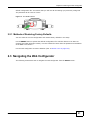
1.6 Hardware Connections
See your Quick Start Guide for information on making hardware connections.
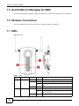
1.7 LEDs
Figure 10 LEDs
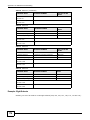
Table 1 LEDs
LABEL
LED
1
SYS
2
18
WLAN
COLOR
STATUS
DESCRIPTION
Green
On
The NWA is receiving power and ready for use.
Red
Flashing
There is system error and the NWA cannot boot up.
On
The NWA doesn’t have an Ethernet connection with the
LAN.
Off
The NWA is not receiving power.
On
The wireless adaptor WLAN is active.
Blinking
The wireless adaptor WLAN is active, and transmitting
or receiving data.
Off
The wireless adaptor WLAN is not active.
Green
NWA1100-N User’s Guide
Chapter 1 Introducing the NWA
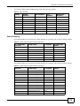
Table 1 LEDs (continued)
LABEL
LED
COLOR
3
ETHERNET
Green
Yellow
NWA1100-N User’s Guide
STATUS
DESCRIPTION
On
The NWA has a 10/100 Mbps Ethernet connection.
Blinking
The NWA has a 10/100 Mbps Ethernet connection and
is sending or receiving data.
On
The NWA has a 1000 Mbps Ethernet connection.
Blinking
The NWA has a 1000 Mbps Ethernet connection and is
sending/receiving data.
Off
The NWA does not have an Ethernet connection.
19
C HAPT ER
2
Introducing the Web Configurator
This chapter describes how to access the NWA’s web configurator and provides an overview of its
screens.
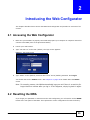
2.1 Accessing the Web Configurator
1
Make sure your hardware is properly connected and prepare your computer or computer network to
connect to the NWA (refer to the Quick Start Guide).
2
Launch your web browser.
3
Type "192.168.1.2" as the URL (default). The login screen appears.
Figure 11 The Login Screen
4
Type “admin” as the (default) username and “1234” as the (default) password. Click Login.
You should now see the Status screen. See Chapter 2 on page 20 for details about the Status
screen.
Note: For security reasons, the NWA automatically logs you out if there is no activity for
longer than five minutes after you log in. If this happens, simply log back in again.
2.2 Resetting the NWA
If you forget your password or cannot access the web configurator, you will need to use the RESET
button at the rear panel of the NWA. This replaces the current configuration file with the factory-
NWA1100-N User’s Guide
20
Chapter 2 Introducing the Web Configurator
default configuration file. This means that you will lose all the settings you previously configured.
The password will be reset to “1234”.
Figure 12 The RESET Button
2.2.1 Methods of Restoring Factory-Defaults
You can erase the current configuration and restore factory defaults in two ways:
Use the RESET button to upload the default configuration file. Hold this button in for about 10
seconds (the lights will begin to blink). Use this method for cases when the password or IP address
of the NWA is not known.
Use the web configurator to restore defaults (refer to Section 15.7 on page 123).
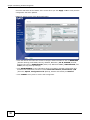
2.3 Navigating the Web Configurator
The following summarizes how to navigate the web configurator from the Status screen.
NWA1100-N User’s Guide
21
Chapter 2 Introducing the Web Configurator
Check the status bar at the bottom of the screen when you click Apply or OK to verify that the
configuration has been updated.
Figure 13 Status Screen of the Web Configurator
• Click the links on the left of the screen to configure advanced features such as WIRELESS
(Wireless Settings, Multi-SSID, Security, RADIUS, MAC Filter), AP IP, SYSTEM (General,
Password and Time), REMOTE MGNT (Telnet, FTP, WWW and SNMP), CERTIFICATES, and
LOGS (View Log and Log Settings).
• Click MAINTENANCE to view information about your NWA or upgrade configuration and
firmware files. Maintenance features include Client Information, Channel Scan, F/W
(firmware) Upload, Configuration File (Backup, Restore and Default) and Reboot.
• Click LOGOUT at any time to exit the web configurator.
22
NWA1100-N User’s Guide
C HAPT ER
3
Status Screens
The Status screens display when you log into the NWA, or click Status in the navigation menu.
Use the Status screens to look at the current status of the device, system resources, and
interfaces. The Status screens also provide detailed information about system statistics, associated
wireless clients, and logs.
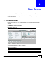
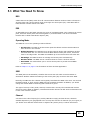
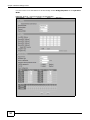
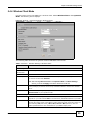
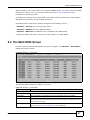
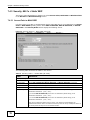
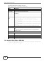
3.1 The Status Screen
Use this screen to get a quick view of system, Ethernet, WLAN and other information regarding
your NWA.
Click Status. The following screen displays.
Figure 14 The Status Screen
The following table describes the labels in this screen.
Table 2 The Status Screen
LABEL
DESCRIPTION
Automatic Refresh
Interval
Select how often you want the NWA to update this screen.
Refresh Now
Click this to update this screen immediately.
System Information
NWA1100-N User’s Guide
23
Chapter 3 Status Screens
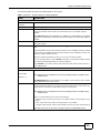
Table 2 The Status Screen (continued)
LABEL
DESCRIPTION
Device Name
This field displays the NWA system name. It is used for identification. You can
change this in the System > General screen’s Device Name field.
WLAN Operating
Mode
This field displays the current operating mode of the first wireless module (Access
Point, Bridge/Repeater, AP+Bridge, Wireless Client, or Multi SSID). You can
change the operating mode in the Wireless > Wireless Settings screen.
Firmware Version
This field displays the current version of the firmware inside the device. It also
shows the date the firmware version was created. You can change the firmware
version by uploading new firmware in Maintenance > F/W Upload.
Current Date Time
This field displays the date and time configured on the NWA. You can change this in
the System > Time Setting screen.
Ethernet Information
LAN MAC Address
This displays the MAC (Media Access Control) address of the NWA on the LAN.
Every network device has a unique MAC address which identifies it across the
network.
IP Address
This field displays the current IP address of the NWA on the network.
Subnet Mask
Subnet masks determine the maximum number of possible hosts on a network.
You can also use subnet masks to divide one network into multiple sub-networks.
Gateway IP Address
This is the IP address of the gateway. The gateway is a router or switch on the
same network segment as the device's LAN port. The gateway helps forward
packets to their destinations.
WLAN Information
SSID
This field displays the SSID (Service Set Identifier).
This is available only when the WLAN Operating Mode is Wireless Client.
Channel
The channel or frequency used by the NWA to send and receive information.
Status
This shows the current status of the wireless LAN.
This is available only when the WLAN Operating Mode is Wireless Client.
Security Mode
This displays the security mode the NWA is using.
This is available only when the WLAN Operating Mode is Wireless Client.
System Resources
System Up Time
This field displays the elapsed time since the NWA was turned on.
CPU Usage
This field displays what percentage of the NWA’s processing ability is currently
being used. The higher the CPU usage, the more likely the NWA is to slow down.
Memory Usage
This field displays what percentage of the NWA’s volatile memory is currently in
use. The higher the memory usage, the more likely the NWA is to slow down. Some
memory is required just to start the NWA and to run the web configurator.
WLAN Associations
This field displays the number of wireless clients currently connected to the NWA’s
wireless network(s).
This is not available when the WLAN Operating Mode is Wireless Client.
Interface Status
Interface
Status
This column displays each interface of the NWA.
This field indicates whether or not the NWA is using the interface.
For each interface, this field displays Up when the NWA is using the interface and
Down when the NWA is not using the interface.
Channel
24
Click this to see which wireless channels are currently in use in the local area. See
Section 15.5 on page 120.
NWA1100-N User’s Guide
Chapter 3 Status Screens
Table 2 The Status Screen (continued)
LABEL
Rate
DESCRIPTION
For the LAN port this displays Auto or the port speed and duplex setting that you
configured in the System > General screen.
For the WLAN interface, it displays the downstream and upstream transmission
rate or N/A if the interface is not in use.
SSID Status
This is not available when the WLAN Operating Mode is Wireless Client.
Interface
This column displays each of the NWA’s wireless interfaces.
SSID
This field displays the SSID(s) currently used by each wireless module.
BSSID
This field displays the MAC address of the wireless module.
Security
This field displays the type of wireless security used by each SSID.
VLAN
This field displays the VLAN ID of each SSID in use, or Disabled if the SSID does
not use VLAN.
System Status
Statistics
Click this link to view port status and packet specific statistics. See Section 3.1.1 on
page 25.
Client Information
Click this to see a list of wireless clients currently associated to each of the NWA’s
wireless modules. See Section 15.4 on page 119.
View Log
Click this to see a list of logs produced by the NWA. See Chapter 14 on page 114.
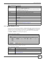
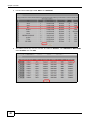
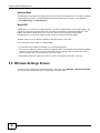
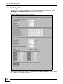
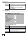
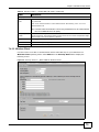
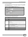
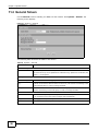
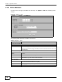
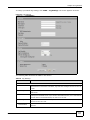
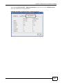
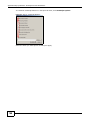
3.1.1 System Statistics Screen
Use this screen to view read-only information, including Wireless Mode, Channel ID, Retry Count
and FCS Error Count. Also provided is the "poll interval". The Poll Interval field is configurable.
The fields in this screen vary according to the current wireless mode of each WLAN adaptor.
Click Status > Statistics. The following screen pops up.
Figure 15 System Status: Statistics
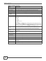
The following table describes the labels in this screen.
Table 3 System Status: Statistics
LABEL
DESCRIPTION
Description
This is the NWA’s wireless LAN module.
Wireless Mode
This field shows which wireless standard the NWA is using.
Channel ID
Click this to see which wireless channels are currently in use in the local area. See
Section 15.5 on page 120.
RX PKT
This is the number of received packets on this port.
NWA1100-N User’s Guide
25
Chapter 3 Status Screens
Table 3 System Status: Statistics (continued)
26
LABEL
DESCRIPTION
TX PKT
This is the number of transmitted packets on this port.
Retry Count
This is the total number of retries for transmitted packets (TX).
FCS Error Count
This is the ratio percentage showing the total number of checksum error of received
packets (RX) over total RX.
Poll Interval
Enter the time interval for refreshing statistics.
Set Interval
Click this button to apply the new poll interval you entered above.
Stop
Click this button to stop refreshing statistics.
NWA1100-N User’s Guide
C HAPT ER
4
Tutorial
This chapter first provides an overview of how to configure the wireless LAN on your NWA, and then
gives step-by-step guidelines showing how to configure your NWA for some example scenarios.
4.1 How to Configure the Wireless LAN
This section illustrates how to choose which wireless operating mode to use on the NWA and how to
set up the wireless LAN in each wireless mode. See Section 4.1.3 on page 28 for links to more
information on each step.
4.1.1 Choosing the Wireless Mode
• Use Access Point operating mode if you want to allow wireless clients to access your wired
network, all using the same security and Quality of Service (QoS) settings. See Section 1.2.1 on
page 12 for details.
• Use Bridge / Repeater operating mode if you want to use the NWA to communicate with other
access points. See Section 1.2.2 on page 12 for details.
• Use AP + Bridge operating mode if you want to use the NWA as an access point (see above)
while also communicating with other access points. See Section 1.2.3 on page 14 for details.
• Use Wireless Client operating mode if you want to use the NWA to access a wireless network.
See Section 1.2.4 on page 15 for details.
The NWA is a bridge when other APs access your wired Ethernet network through the NWA.
• Use Multi SSID (Multiple Basic Service Set Identifier) operating mode if you want to use the
NWA as an access point with some groups of users having different security or QoS settings from
other groups of users. See Section 1.2.5 on page 16 for details.
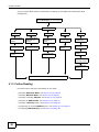
4.1.2 Wireless LAN Configuration Overview
The following figure shows the steps you should take to configure the wireless settings according to
the operating mode you select. Use the Web Configurator to set up your NWA’s wireless network
NWA1100-N User’s Guide
27
Chapter 4 Tutorial
(see your Quick Start Guide for information on setting up your NWA and accessing the Web
Configurator).
Select the WLAN Adaptor you want to configure.
Select Operation Mode.
Access Point
Bridge / Repeater
AP + Bridge
Wireless Client
Select Wireless Mode,
SSID Profile, and
Channel.
Select Wireless Mode,
SSID Profile, and
Channel.
Select Wireless Mode,
SSID Profile, and
Channel.
Select the AP you
want to connect to.
Configure RADIUS
authentication (optional).
Configure RADIUS
authentication (optional).
Configure RADIUS
authentication (optional).
Configure Security
Settings.
Configure MAC Filter
(optional).
Configure MAC Filter
(optional).
Multi SSID
Select Wireless Mode
and SSID Profile.
Configure the selected
SSID Profiles.
Configure Security
Settings.
Configure RADIUS
authentication (optional).
Configure MAC Filter
(optional).
Check your settings and test.
4.1.3 Further Reading
Use these links to find more information on the steps:
• Selecting Operation Mode: see Section 5.4 on page 50.
• Choosing Wireless Mode: see Section 5.4 on page 50.
• Choosing a wireless Channel: see Section 5.4 on page 50.
• Choosing an SSID Profile: see Section 5.4 on page 50
• Choosing a Security mode: see Section 6.2 on page 67.
• Configuring an external RADIUS server: see Section 8.4 on page 85.
• Configuring MAC Filtering: see Section 9.4 on page 88.
28
NWA1100-N User’s Guide
Chapter 4 Tutorial
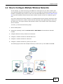
4.2 How to Configure Multiple Wireless Networks
In this example, you have been using your NWA as an access point for your office network (See
your Quick Start Guide for information on how to set up your NWA in Access Point mode). Now your
network is expanding and you want to make use of the Multi-SSID feature (see Multi SSID on page
50) to provide multiple wireless networks. Each wireless network will cater to a different type of
user.
You want to make three wireless networks: one standard office wireless network with all the same
settings you already have, another wireless network with high priority QoS settings for Voice over
IP (VoIP) users, and a guest network that prevents visitors in this network from communicating
with one another.
To do this, you will take the following steps:
1
Edit the SSID profiles.
2
Change the operating mode from Access Point to Multi SSID and reactivate the standard
network.
3
Configure different security modes for the networks.
4
Configure a wireless network for standard office use.
5
Configure a wireless network for VoIP users.
6
Configure a wireless network for guests to your office.
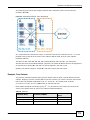
The following figure shows the multiple networks you want to set up. Your NWA is marked Z.
Z
NWA1100-N User’s Guide
29
Chapter 4 Tutorial
The standard network (SSID01) has access to all resources. The VoIP network (VoIP_SSID) has
access to all resources and a high QoS priority. The guest network (Guest_SSID) has a low QoS
priority and prevents visitors in this network from communicating with one another.
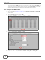
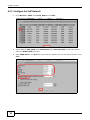
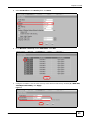
4.2.1 Configure the SSID Profiles
30
1
Log in to the NWA (see Section 2.1 on page 20). Click Wireless > Multi SSID. The Multi SSID
screen appears.
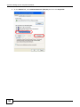
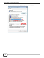
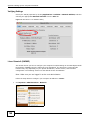
2
Select the Profile1 radio button and click Edit.
3
Rename the Profile Name as SSID01. Click Save.
4
Repeat Step 2 and 3 to change Profile2 and Profile3 to VoIP_SSID and Guest_SSID.
NWA1100-N User’s Guide
Chapter 4 Tutorial
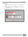
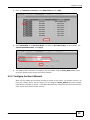
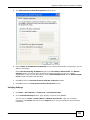
4.2.1.1 Multi SSID
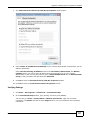
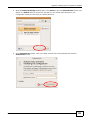
1
Go to Wireless > Wireless Settings. Select Multi SSID from the Operating Mode drop-down
list box.
2
SSID01 is the standard network, so select SSID01 as the first profile. It is always active.
3
Select VoIP_SSID as the second profile, and Guest_SSID as the third profile. Select the
corresponding Active check-boxes.
4
Click Apply to save your settings. Now the three SSIDs are activated.
NWA1100-N User’s Guide
31
Chapter 4 Tutorial
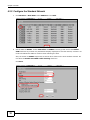
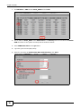
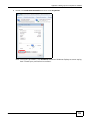
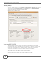
4.2.2 Configure the Standard Network
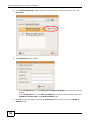
1
Click Wireless > Multi SSID. Select SSID01 and click Edit.
2
Set the SSID to SSID01. Select SecProfile1 as SSID01’s security profile. Select the Hidden
SSID checkbox as you want only authorized company employees to use this network, so there is no
need to broadcast the SSID to wireless clients scanning the area.
Also, the clients on SSID01 might need to access other clients on the same wireless network. Do
not select the Enable Intra-BSS Traffic blocking check-box.
Click Save.
32
NWA1100-N User’s Guide
Chapter 4 Tutorial
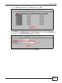
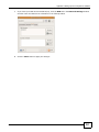
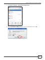
3
Next, click Wireless > Security. Select SecProfile1 and click Edit.
4
Since SSID01 is the standard network that has access to all resources, assign a more secure
security mode. Select WPA2-PSK-MIX as the Security Mode, and enter the Pre-Shared Key. In
this example, use ThisisSSID01PreSharedKey. Click Apply.
5
You have finished configuring the standard network, SSID01.
NWA1100-N User’s Guide
33
Chapter 4 Tutorial
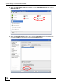
4.2.3 Configure the VoIP Network
34
1
Go to Wireless > SSID. Select VoIP_SSID and click Edit.
2
Set the SSID to VoIP_SSID. Select SecProfile2 as the Security Profile for the VoIP network.
Select the Hidden SSID check-box.
3
Select WMM-Voice in the QoS field to give VoIP the highest priority in the wireless network. Click
Save.
NWA1100-N User’s Guide
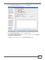
Chapter 4 Tutorial
4
Next, click Wireless > Security. Select SecProfile2 and click Edit.
5
Select WPA2-PSK as the Security Mode, and enter the Pre-Shared Key. In this example, use
ThisisVoIPPreSharedKey. Click Apply.
6
Your VoIP wireless network is now ready to use. Any traffic using the VoIP_SSID profile will be
given the highest priority across the wireless network.
4.2.4 Configure the Guest Network
When you are setting up the wireless network for guests to your office, your primary concern is to
keep your network secure. For this reason, the pre-configured Guest_SSID profile has intra-BSS
traffic blocking enabled by default. “Intra-BSS traffic blocking” means that the client cannot access
other clients on the same wireless network.
NWA1100-N User’s Guide
35
Chapter 4 Tutorial
36
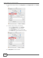
1
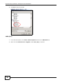
Click Wireless > SSID. Select Guest_SSID and click Edit.
2
Set the SSID to Guest_SSID. Select SecProfile3 in the Security field. Do not select the Hidden
SSID check-box so the guests can easily find the wireless network.
3
Select WMM-best effort in the QoS field t
4
o give the guest a lower QoS priority.
5
Select the check-box of Enable Intra-BSS Traffic blocking. Click Save.
NWA1100-N User’s Guide
Chapter 4 Tutorial
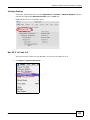
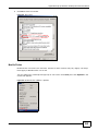
6
Next, click Wireless > Security. Select SecProfile3 and click Edit.
7
Select WPA-PSK in the Security Mode field. WPA-PSK provides strong security that is supported
by most wireless clients.
8
Enter the PSK you want to use in your network in the Pre-Shared Key field. In this example, the
PSK is ThisismyGuestWPApre-sharedkey. Click Apply.
9
Your guest wireless network is now ready to use.
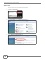
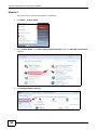
4.2.5 Testing the Wireless Networks
To make sure that the three networks are correctly configured, do the following.
• On a computer with a wireless client, scan for access points. You should see the Guest_SSID
network, but not the SSID01 and VoIP_SSID networks. If you can see the SSID01 and
VoIP_SSID networks, go to its SSID Edit screen and make sure to select the Hidden SSID
check-box and click Save.
• Try to access each network using the correct security settings, and then using incorrect security
settings, such as the WPA-PSK for another active network. If the behavior is different from
expected (for example, if you can access the SSID01 or VoIP_SSID wireless network using the
security settings for the Guest_SSID wireless network) check that the SSID profile is set to use
the correct security profile, and that the settings of the security profile are correct.
NWA1100-N User’s Guide
37
Chapter 4 Tutorial
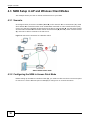
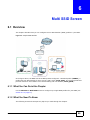
4.3 NWA Setup in AP and Wireless Client Modes
This example shows you how to restrict wireless access to your NWA.
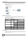
4.3.1 Scenario
In the figure below, there are two NWAs (A and B) in the network. A is in Access Point (AP) mode
while station B is in Wireless Client mode. Station B is connected to a File Transfer Protocol (FTP)
server. You want only specified wireless clients to be able to access station B. You also want to allow
wireless traffic between B and wireless clients connected to A (W, Y and Z). Other wireless devices
(X) must not be able to connect to the FTP server.
Figure 16 FTP Server Connected to a Wireless Client
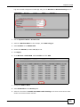
4.3.2 Configuring the NWA in Access Point Mode
Before setting up the NWA as a wireless client (B), you need to make sure there is an access point
to connect to. Use the Ethernet port on NWA (A) to configure it via a wired connection.
38
NWA1100-N User’s Guide
Chapter 4 Tutorial
Log into the Web Configurator on NWA (A) and go to the Wireless > Wireless Settings screen.
1
Set the Operation Mode to Access Point.
2
Select the Wireless Mode. In this example, select 802.11b/g/n.
3
Select Profile1 as the SSID Profile.
4
Choose the Channel you want NWA (A) to use.
5
Click Apply.
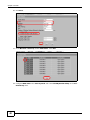
6
Go to Wireless > Multi SSID. Select Profile1 and click Edit.
7
Change the SSID to AP-A.
8
Select SecProfile1 in the Security field.
9
Select the check-box for Enable Intra-BSS Traffic blocking so the client cannot access other
clients on the same wireless network.
NWA1100-N User’s Guide
39
Chapter 4 Tutorial
10 Click Save.
11 Go to Wireless > Security. Select SecProfile1. Click Edit.
12 Configure WPA-PSK as the Security Mode and enter ThisisMyPreSharedKey in the PreShared Key field.
40
NWA1100-N User’s Guide
Chapter 4 Tutorial
13 Click Apply to finish configuration for NWA (A).
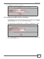
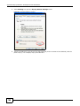
4.3.3 Configuring the NWA in Wireless Client Mode
The NWA (B) should have a wired connection before it can be set to wireless client operating mode.
Connect your NWA to the FTP server. Login to NWA (B)’s Web Configurator and go to the Wireless
> Wireless Settings screen. Follow these steps to configure station B.
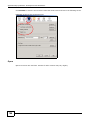
1
Select Wireless Client as Operation Mode. Select Profile1 as the SSID Profile. Click Apply.
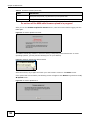
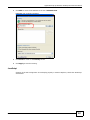
2
Click on the Site Survey tab. A window should pop up which contains a list of all available wireless
devices within your NWA’s range.
NWA1100-N User’s Guide
41
Chapter 4 Tutorial
42
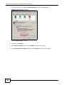
3
Find and select NWA (A)’s SSID: AP-A. Click Selected.
4
The NWA automatically uses the selected AP’s SSID for Profile 1. Go to Wireless > Multi SSID.
Select Profile1 and click Edit.
NWA1100-N User’s Guide
Chapter 4 Tutorial
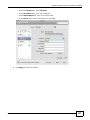
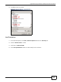
5
Select SecProfile1 in the Security field. Click Save.
6
Go to Wireless > Security. Select SecProfile1. Click Edit.
7
Configure the NWA to use the same security mode and Pre-Shared Key as NWA (A): WPA-PSK/
ThisisMyPreSharedKey. Click Apply.
Figure 17
NWA1100-N User’s Guide
43
Chapter 4 Tutorial
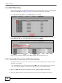
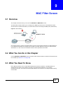
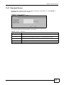
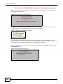
4.3.4 MAC Filter Setup
One way to ensure that only specified wireless clients can access the FTP server is by enabling MAC
filtering on NWA (B) (See Chapter 9 on page 87 for more information on MAC Filter).
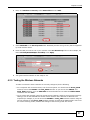
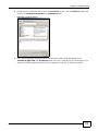
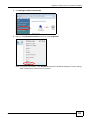
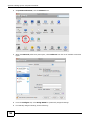
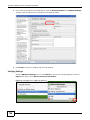
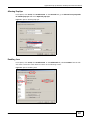
1
Go to Wireless > MAC Filter. Select MacProfile1 and click Edit.
2
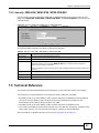
Select Allow Listed in the Access Control Mode field. Enter the MAC addresses of the wireless
clients (W, Y and Z) you want to associate with the NWA. Click Apply.
Now, only the authorized wireless clients (W, Y and Z) can access the FTP server.
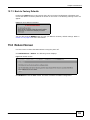
4.3.5 Testing the Connection and Troubleshooting
This section discusses how you can check if you have correctly configured your network setup as
described in this tutorial.
• Try accessing the FTP server from wireless clients W, Y or Z. Test if you can send or retrieve a
file. If you cannot establish a connection with the FTP server, do the following steps.
44
1
Make sure W, Y and Z use the same wireless security settings as A and can access A.
2
Make sure B uses the same wireless and wireless security settings as A and can access A.
NWA1100-N User’s Guide
Chapter 4 Tutorial
3
Make sure intra-BSS traffic is enabled on A.
• Try accessing the FTP server from X. If you are able to access the FTP server, do the following.
1
Make sure MAC filtering is enabled.
2
Make sure X’s MAC address is not entered in the list of allowed devices.
NWA1100-N User’s Guide
45
P ART II
Technical Reference
The appendices provide general information. Some details may not apply to your NWA.
46
47
C HAPT ER
5
Wireless Settings Screen
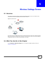
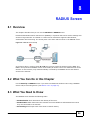
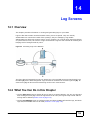
5.1 Overview
This chapter discusses the steps to configure the Wireless Settings screen on the NWA. It also
introduces the wireless LAN (WLAN) and some basic scenarios.
Figure 18 Wireless Mode
In the figure above, the NWA allows access to another bridge device (A) and a notebook computer
(B) upon verifying their settings and credentials. It denies access to other devices (C and D) with
configurations that do not match those specified in your NWA.
5.2 What You Can Do in this Chapter
Use the Wireless > Wireless Settings screen to configure the NWA’s operation mode (see
Section 5.4 on page 50).
NWA1100-N User’s Guide
48
Chapter 5 Wireless Settings Screen
5.3 What You Need To Know
BSS
A Basic Service Set (BSS) exists when all communications between wireless clients or between a
wireless client and a wired network client go through one access point (AP). Intra-BSS traffic is
traffic between wireless clients in the BSS.
ESS
An Extended Service Set (ESS) consists of a series of overlapping BSSs, each containing an access
point, with each access point connected together by a wired network. This wired connection
between APs is called a Distribution System (DS).
Operating Mode
The NWA can run in four operating modes as follows:
• Access Point. The NWA is wireless access point that allows wireless communication to
other devices in the network.
• Bridge/Repeater. The NWA acts as a wireless network bridge and establishes wireless
links with other APs. You need to know the MAC address of the peer device, which also
must be in bridge mode. The NWA can establish up to five wireless links with other APs.
• AP+Bridge. The NWA functions as a bridge and access point simultaneously.
• Wireless Client. The NWA acts as a wireless client to access a wireless network.
• Multi SSID. This mode allows you to use one access point to provide several BSSs
simultaneously.
Refer to Chapter 1 on page 11 for illustrations of these wireless applications.
SSID
The SSID (Service Set IDentifier) identifies the Service Set with which a wireless station is
associated. Wireless stations associating to the access point (AP) must have the same SSID.
Normally, the NWA acts like a beacon and regularly broadcasts the SSID in the area. You can hide
the SSID instead, in which case the NWA does not broadcast the SSID. In addition, you should
change the default SSID to something that is difficult to guess.
This type of security is fairly weak, however, because there are ways for unauthorized wireless
devices to get the SSID. In addition, unauthorized wireless devices can still see the information that
is sent in the wireless network.
Channel
A channel is the radio frequency(ies) used by IEEE 802.11a/b/g wireless devices. Channels
available depend on your geographical area. You may have a choice of channels (for your region) so
you should use a different channel than an adjacent AP (access point) to reduce interference.
NWA1100-N User’s Guide
49
Chapter 5 Wireless Settings Screen
Wireless Mode
The IEEE 802.1x standard was designed to extend the features of IEEE 802.11 to support extended
authentication as well as providing additional accounting and control features. Your NWA can
support 802.11b/g and 802.11b/g/n.
Multi SSID
Traditionally, you needed to use different APs to configure different Basic Service Sets (BSSs). As
well as the cost of buying extra APs, there was also the possibility of channel interference. The
NWA’s multi-SSID function allows you to use one access point to provide several BSSs
simultaneously. You can then assign varying levels of privilege to different SSIDs.
Wireless stations can use different SSIDs to associate with the same AP.
The following are some notes on multiple SSIDs.
• A maximum of four BSSs are allowed on one AP simultaneously.
• You must use different security settings for different BSSs. If two stations have different BSSIDs
(they are in different BSSs), but have the same security settings, they may hear each other’s
communications (but not communicate with each other).
• Multi-SSID should not replace but rather be used in conjunction with 802.1x security.
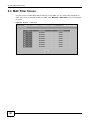
5.4 Wireless Settings Screen
Use this screen to choose the operating mode for your NWA. Click Wireless > Wireless Settings.
The screen varies depending upon the operating mode you select.
50
NWA1100-N User’s Guide
Chapter 5 Wireless Settings Screen
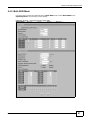
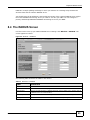
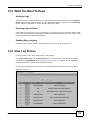
5.4.1 Access Point Mode
Use this screen to use your NWA as an access point. Select Access Point as the Operation Mode.
The following screen displays.
Figure 19 Wireless > Wireless Settings: Access Point
The following table describes the general wireless LAN labels in this screen.
Table 4 Wireless > Wireless Settings: Access Point
LABEL
DESCRIPTION
Basic Settings
Disable Wireless
LAN Interface
Select this option to turn off the wireless LAN.
Operation Mode
Select Access Point from the drop-down list.
NWA1100-N User’s Guide
51
Chapter 5 Wireless Settings Screen
Table 4 Wireless > Wireless Settings: Access Point (continued)
LABEL
DESCRIPTION
Wireless Mode
Select 802.11b/g to allow both IEEE802.11b and IEEE802.11g compliant WLAN devices
to associate with the NWA. The transmission rate of your NWA might be reduced.
Select 802.11b/g/n to allow IEEE802.11b, IEEE802.11g and IEEE802.11n compliant
WLAN devices to associate with the Device. The transmission rate of the NWA might be
reduced.
SSID Profile
The SSID (Service Set IDentifier) identifies the Service Set with which a wireless station is
associated. Wireless stations associating to the access point (AP) must have the same
SSID. Select an SSID Profile from the drop-down list box.
Note: If you are configuring the NWA from a computer connected to the wireless LAN and
you change the NWA’s SSID or security settings, you will lose your wireless
connection when you press Apply to confirm. You must then change the wireless
settings of your computer to match the NWA’s new settings.
Channel
Select the operating frequency/channel depending on your particular region from the
drop-down list box.
Channel Width
This field displays only when you select 802.11 b/g/n in the 802.11 Wireless Mode
field.
A standard 20MHz channel offers transfer speeds of up to 150Mbps whereas a 40MHz
channel uses two standard channels and offers speeds of up to 300Mbps. However, not all
devices support 40MHz channels.
Select the channel bandwidth you want to use for your wireless network.
It is recommended that you select 20/40 (20/40 MHz). This allows the NWA to adjust the
channel bandwidth depending on network conditions.
Select 20 MHz if you want to lessen radio interference with other wireless devices in your
neighborhood.
Advanced Settings
Click + or - to display or hide the following fields.
Beacon Interval
When a wirelessly network device sends a beacon, it includes with it a beacon interval.
This specifies the time period before the device sends the beacon again. The interval tells
receiving devices on the network how long they can wait in lowpower mode before waking
up to handle the beacon. A high value helps save current consumption of the access point.
DTIM Interval
Delivery Traffic Indication Message (DTIM) is the time period after which broadcast and
multicast packets are transmitted to mobile clients in the Active Power Management
mode. A high DTIM value can cause clients to lose connectivity with the network.
Output Power
Set the output power of the NWA in this field. If there is a high density of APs in an area,
decrease the output power of the NWA to reduce interference with other APs. Select one
of the following Full (Full Power), 50%, 25%, 12.5% or Min (Minimum). See the
product specifications for more information on your NWA’s output power.
Preamble Type
Select Dynamic to have the AP automatically use short preamble when wireless adapters
support it, otherwise the AP uses long preamble.
Select Long if you are unsure what preamble mode the wireless adapters support, and to
provide more reliable communications in busy wireless networks.
52
RTS/CTS
Threshold
(Request To Send) The threshold (number of bytes) for enabling RTS/CTS handshake.
Data with its frame size larger than this value will perform the RTS/CTS handshake.
Setting this attribute to be larger than the maximum MSDU (MAC service data unit) size
turns off the RTS/CTS handshake. Setting this attribute to its smallest value (1) turns on
the RTS/CTS handshake.
Fragmentation
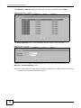
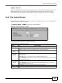
The threshold (number of bytes) for the fragmentation boundary for directed messages. It
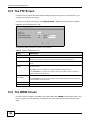
is the maximum data fragment size that can be sent.
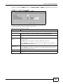
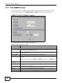
NWA1100-N User’s Guide
Chapter 5 Wireless Settings Screen
Table 4 Wireless > Wireless Settings: Access Point (continued)
LABEL
DESCRIPTION
A-MPDU
aggregation
This field is available only when 802.11 b/g/n is selected as the Wireless Mode. Select
Enable to allow the grouping of several A-MSDUs (Aggregate MAC Service Data Units)
into one large A-MPDU (Aggregate MAC Protocol Data Unit). This function allows faster
data transfer rates.
Short GI
This field is available only when 802.11 b/g/n is selected as the Wireless Mode. Select
Enable to use Short GI (Guard Interval). The guard interval is the gap introduced
between data transmission from users in order to reduce interference. Reducing the GI
increases data transfer rates but also increases interference. Increasing the GI reduces
data transfer rates but also reduces interference.
Rates
Configuration
This section controls the data rates permitted for clients.
For each Rate, select an option from the Configuration list. The options are:
•
•
•
MCS Table
Basic (1~11 Mbps only): Clients can always connect to the access point at this speed.
Optional: Clients can connect to the access point at this speed, when permitted to do
so by the AP.
Disable: Clients cannot connect to the access point at this speed.
The MCS Rate table is available only when 802.11 b/g/n is selected in the 802.11
Wireless Mode field.
IEEE 802.11n supports many different data rates which are called MCS rates. MCS stands
for Modulation and Coding Scheme. This is an 802.11n feature that increases the wireless
network performance in terms of throughput.
For each MCS Rate (0-15), select either Enable (default) to have the NWA use the data
rate. Select Disable if you do not want the NWA to use the data rate.
Apply
Click Apply to save your changes.
Cancel
Click Cancel to begin configuring this screen afresh.
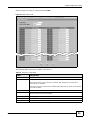
5.4.2 Bridge / Repeater Mode
Use this screen to have the NWA act as a wireless network bridge and establish wireless links with
other APs. You need to know the MAC address of the peer device, which also must be in bridge
mode.
NWA1100-N User’s Guide
53
Chapter 5 Wireless Settings Screen
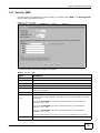
Use this screen to use the NWA as a wireless bridge. Select Bridge/Repeater as the Operation
Mode.
Figure 20 Wireless > Wireless Settings: Bridge/Repeater
54
NWA1100-N User’s Guide
Chapter 5 Wireless Settings Screen
The following table describes the bridge labels in this screen.
Table 5 Wireless > Wireless Settings: Bridge/Repeater
LABEL
DESCRIPTIONS
Basic Settings
Disable Wireless LAN
Interface
Select this option to turn off the wireless LAN.
Operation Mode
Select Bridge/Repeater in this field.
Wireless Mode
Select 802.11b/g to allow both IEEE802.11b and IEEE802.11g compliant WLAN
devices to associate with the NWA. The transmission rate of your NWA might be
reduced.
Select 802.11b/g/n to allow IEEE802.11b, IEEE802.11g and IEEE802.11n compliant
WLAN devices to associate with the NWA. The transmission rate of the NWA might be
reduced.
Channel
Select the operating frequency/channel depending on your particular region from the
drop-down list box.
Channel Width
This field displays only when you select 802.11 b/g/n in the 802.11 Wireless Mode
field.
A standard 20MHz channel offers transfer speeds of up to 150Mbps whereas a 40MHz
channel uses two standard channels and offers speeds of up to 300Mbps. However, not
all devices support 40MHz channels.
Select the channel bandwidth you want to use for your wireless network.
It is recommended that you select 20/40 (20/40 MHz). This allows the NWA to adjust
the channel bandwidth depending on network conditions.
Select 20 MHz if you want to lessen radio interference with other wireless devices in
your neighborhood.
WDS Settings
Local Mac Address
Remote MAC
Address 1 - 4
A Wireless Distribution System is a wireless connection between two or more APs.
Note: WDS security is independent of the security settings between the NWA and any
wireless clients.
Local MAC Address is the MAC address of your NWA. You can specify up to 4 remote
devices’ MAC addresses in this section.
Enable WDS Security
Select this to turn on security for the NWA’s Wireless Distribution System (WDS). A
Wireless Distribution System is a wireless connection between two or more APs. If you
do not select the check box, traffic between APs is not encrypted.
Note: WDS security is independent of the security settings between the NWA and any
wireless clients.
When you enable WDS security, also do the following:
•
•
•
Select the type of security you want to use (TKIP or AES) to secure traffic on your
WDS.
Enter a pre-shared key (PSK) for access point(s) in your WDS.
Configure WDS security and the relevant PSK in each of your other access point(s).
Note: Other APs must use the same encryption method to enable WDS security.
NWA1100-N User’s Guide
55
Chapter 5 Wireless Settings Screen
Table 5 Wireless > Wireless Settings: Bridge/Repeater (continued)
LABEL
DESCRIPTIONS
Encryption Type
This field is configurable only when you select Enable WDS Security.
Select TKIP to enable Temporal Key Integrity Protocol (TKIP) security on your WDS.
This option is compatible with other ZyXEL access points that support WDS security.
Use this if the other access points on your network support WDS security but do not
have an AES option.
Note: Check your other AP’s documentation to make sure it supports WDS security.
Select AES to enable Advanced Encryption System (AES) security on your WDS. AES
provides superior security to TKIP. Use AES if the other access points on your
network support it for the WDS.
Encryption Key
Type a pre-shared key (PSK) from 8 to 63 case-sensitive ASCII characters (including
spaces and symbols). You must also set the peer device to use the same pre-shared
key.
Advanced Settings
Click + or - to display or hide the following fields.
Output Power
Set the output power of the NWA in this field. If there is a high density of APs in an
area, decrease the output power of the NWA to reduce interference with other APs.
Select one of the following Full (Full Power), 50%, 25%, 12.5% or Min (Minimum).
See the product specifications for more information on your NWA’s output power.
Preamble Type
Select Dynamic to have the AP automatically use short preamble when wireless
adapters support it, otherwise the AP uses long preamble.
Select Long if you are unsure what preamble mode the wireless adapters support, and
to provide more reliable communications in busy wireless networks.
RTS/CTS Threshold
(Request To Send) The threshold (number of bytes) for enabling RTS/CTS handshake.
Data with its frame size larger than this value will perform the RTS/CTS handshake.
Setting this attribute to be larger than the maximum MSDU (MAC service data unit)
size turns off the RTS/CTS handshake. Setting this attribute to its smallest value (1)
turns on the RTS/CTS handshake.
Fragmentation
The threshold (number of bytes) for the fragmentation boundary for directed
messages. It is the maximum data fragment size that can be sent.
A-MPDU aggregation
This field is available only when 802.11 b/g/n is selected as the Wireless Mode.
Select Enable to allow the grouping of several A-MSDUs (Aggregate MAC Service Data
Units) into one large A-MPDU (Aggregate MAC Protocol Data Unit). This function allows
faster data transfer rates.
Short GI
This field is available only when 802.11 b/g/n is selected as the Wireless Mode.
Select Enable to use Short GI (Guard Interval). The guard interval is the gap
introduced between data transmission from users in order to reduce interference.
Reducing the GI increases data transfer rates but also increases interference.
Increasing the GI reduces data transfer rates but also reduces interference.
Rates Configuration
This section controls the data rates permitted for clients.
For each Rate, select an option from the Configuration list. The options are:
•
•
•
56
Basic (1~11 Mbps only): Clients can always connect to the access point at this
speed.
Optional: Clients can connect to the access point at this speed, when permitted to
do so by the AP.
Disable: Clients cannot connect to the access point at this speed.
NWA1100-N User’s Guide
Chapter 5 Wireless Settings Screen
Table 5 Wireless > Wireless Settings: Bridge/Repeater (continued)
LABEL
DESCRIPTIONS
MCS Table
The MCS Rate table is available only when 802.11 b/g/n is selected in the 802.11
Wireless Mode field.
IEEE 802.11n supports many different data rates which are called MCS rates. MCS
stands for Modulation and Coding Scheme. This is an 802.11n feature that increases
the wireless network performance in terms of throughput.
For each MCS Rate (0-15), select either Enable (default) to have the NWA use the
data rate. Select Disable if you do not want the NWA to use the data rate.
Apply
Click Apply to save your changes.
Cancel
Click Cancel to begin configuring this screen afresh.
NWA1100-N User’s Guide
57
Chapter 5 Wireless Settings Screen
5.4.3 AP + Bridge Mode
Use this screen to have the NWA function as a bridge and access point simultaneously. Select
AP+Bridge as the Operation Mode. The following screen displays.
Figure 21 Wireless > Wireless Settings: AP+Bridge
See the tables describing the fields in the Access Point and Bridge / Repeater operating modes
for descriptions of the fields in this screen.
58
NWA1100-N User’s Guide
Chapter 5 Wireless Settings Screen
5.4.4 Wireless Client Mode
Use this screen to turn your NWA into a wireless client. Select Wireless Client as the Operation
Mode. The following screen displays.
Figure 22 Wireless > Wireless Settings: Wireless Client
The following table describes the general wireless LAN labels in this screen.
Table 6 Wireless > Wireless Settings: Wireless Client
LABEL
DESCRIPTION
Basic Settings
Disable Wireless
LAN Interface
Select this option to turn off the wireless LAN.
Operation Mode
Select Wireless Client in this field.
Site Survey
Click this to view a list of available wireless access points within the range. Select the AP
you want to use and click Selected.
Note: After selecting Wireless Client as the Operation Mode in the Basic Settings
section, you must click Apply to be able to select from the AP list.
SSID Profile
Select an SSID Profile from the drop-down list box. The SSID profile defines the SSID and
security settings you want to use to set up a wireless network or connect to a wireless
device.
Channel
This shows the operating frequency/channel in use. This field is read-only when you select
Wireless Client as your operation mode.
Advanced Settings
MAC Clone
Choose Manual to configure the NWA’s MAC address by cloning the MAC address from a
computer on your LAN. Choose Auto to use the factory default MAC address of your NWA.
Output Power
Set the output power of the NWA in this field. If there is a high density of APs in an area,
decrease the output power of the NWA to reduce interference with other APs. Select one
of the following Full (Full Power), 50%, 25%, 12.5% or Min (Minimum). See the
product specifications for more information on your NWA’s output power.
NWA1100-N User’s Guide
59
Chapter 5 Wireless Settings Screen
Table 6 Wireless > Wireless Settings: Wireless Client (continued)
LABEL
DESCRIPTION
Preamble Type
Select Dynamic to have the NWA automatically use short preamble when the wireless
network your NWA is connected to supports it, otherwise the NWA uses long preamble.
Select Long preamble if you are unsure what preamble mode the wireless device your
NWA is connected to supports, and to provide more reliable communications in busy
wireless networks.
60
RTS/CTS
Threshold
(Request To Send) The threshold (number of bytes) for enabling RTS/CTS handshake.
Data with its frame size larger than this value will perform the RTS/CTS handshake.
Setting this attribute to be larger than the maximum MSDU (MAC service data unit) size
turns off the RTS/CTS handshake. Setting this attribute to its smallest value (1) turns on
the RTS/CTS handshake.
Extension
channel
protection mode
You can use CTS to self or RTS-CTS protection mechanism to reduce conflicts with other
wireless networks or hidden wireless clients. The throughput of RTS-CTS is much lower
than CTS to self. Using this mode may decrease your wireless performance.
A-MPDU
aggregation
This field is available only when 802.11 b/g/n is selected as the Wireless Mode. Select
Enable to allow the grouping of several A-MSDUs (Aggregate MAC Service Data Units)
into one large A-MPDU (Aggregate MAC Protocol Data Unit). This function allows faster
data transfer rates.
Short GI
This field is available only when 802.11 b/g/n is selected as the Wireless Mode. Select
Enable to use Short GI (Guard Interval). The guard interval is the gap introduced
between data transmission from users in order to reduce interference. Reducing the GI
increases data transfer rates but also increases interference. Increasing the GI reduces
data transfer rates but also reduces interference.
Apply
Click Apply to save your changes.
Cancel
Click Cancel to begin configuring this screen afresh.
NWA1100-N User’s Guide
Chapter 5 Wireless Settings Screen
5.4.5 Multi SSID Mode
Use this screen to have the NWA function in Multi SSID mode. Select Multi SSID as the
Operating Mode. The following screen diplays.
Figure 23 Wireless > Wireless Settings: Multi SSID
NWA1100-N User’s Guide
61
Chapter 5 Wireless Settings Screen
The following table describes the labels in this screen.
Table 7 Wireless > Wireless Settings: Multi SSID
LABEL
DESCRIPTION
Disable Wireless LAN
Interface
Select this option to turn off the wireless LAN.
Operating Mode
Select Multi SSID in this field.
Wireless Mode
Select 802.11b/g to allow both IEEE802.11b and IEEE802.11g compliant WLAN
devices to associate with the NWA. The transmission rate of your NWA might be
reduced.
Select 802.11b/g/n to allow IEEE802.11b, IEEE802.11g and IEEE802.11n
compliant WLAN devices to associate with the NWA. The transmission rate of the NWA
might be reduced.
Channel
Select the operating frequency/channel depending on your particular region from the
drop-down list box.
Channel Width
This field displays only when you select 802.11 b/g/n in the 802.11 Wireless
Mode field.
A standard 20MHz channel offers transfer speeds of up to 150Mbps whereas a 40MHz
channel uses two standard channels and offers speeds of up to 300Mbps. However,
not all devices support 40MHz channels.
Select the channel bandwidth you want to use for your wireless network.
It is recommended that you select 20/40 (20/40 MHz). This allows the NWA to
adjust the channel bandwidth depending on network conditions.
Select 20 MHz if you want to lessen radio interference with other wireless devices in
your neighborhood.
Select SSID Profile
An SSID profile is the set of parameters relating to one of the NWA’s BSSs. The SSID
(Service Set IDentifier) identifies the Service Set with which a wireless station is
associated. Wireless stations associating with the access point (AP) must have the
same SSID.
If you are configuring the NWA from a computer connected to the wireless LAN and
you change the NWA’s SSID or security settings, you will lose your wireless
connection when you press Apply to confirm. You must then change the wireless
settings of your computer to match the NWA’s new settings.
Index
Select the check box to activate an SSID profile.
Active
Select the check box to enable the bridge connection. Otherwise, clear the check box
to disable it. The first profile is always active.
Profile
Select the profile(s) of the SSIDs you want to use in your wireless network. You can
have up to four BSSs running on the NWA simultaneously.
Configure SSID profiles in the Multi SSID screen.
Tag
This displays whether traffic from this SSID is tagged with the VLAN ID.
This field is configurable only when you enable 802.1Q VLAN tagging in the System >
General screen.
Select the check box to enable VLAN tagging for this SSID.
VLAN
This displays the VLAN ID associated with the SSID.
This field is configurable only when you enable 802.1Q VLAN tagging in the System >
General screen and select the Tag check box in this screen.
Enter a VLAN ID number from 1 to 4094. Packets coming from the WLAN using this
SSID profile are tagged with the VLAN ID number by the NWA. Different BSSID
profiles can use the same or different VLAN IDs. This allows you to split wireless
stations into groups using similar VLAN IDs.
62
NWA1100-N User’s Guide
Chapter 5 Wireless Settings Screen
Table 7 Wireless > Wireless Settings: Multi SSID (continued)
LABEL
DESCRIPTION
QoS
This displays the QoS priority level associated with the SSID.
This field is configurable only when you enable 802.1Q VLAN tagging in the System >
General screen and select the Tag check box in this screen.
Select the Quality of Service priority for this BSS’s traffic.
Advanced Settings
Beacon Interval
When a wirelessly networked device sends a beacon, it includes with it a beacon
interval. This specifies the time period before the device sends the beacon again. The
interval tells receiving devices on the network how long they can wait in lowpower
mode before waking up to handle the beacon. A high value helps save current
consumption of the access point.
DTIM Interval
Delivery Traffic Indication Message (DTIM) is the time period after which broadcast
and multicast packets are transmitted to mobile clients in the Active Power
Management mode. A high DTIM value can cause clients to lose connectivity with the
network.
Output Power
Set the output power of the NWA in this field. If there is a high density of APs in an
area, decrease the output power of the NWA to reduce interference with other APs.
Select one of the following Full (Full Power), 50%, 25%, 12.5% or Min (Minimum).
See the product specifications for more information on your NWA’s output power.
Preamble Type
Select Dynamic to have the AP automatically use short preamble when wireless
adapters support it, otherwise the AP uses long preamble.
Select Long if you are unsure what preamble mode the wireless adapters support,
and to provide more reliable communications in busy wireless networks.
RTS/CTS Threshold
(Request To Send) The threshold (number of bytes) for enabling RTS/CTS handshake.
Data with its frame size larger than this value will perform the RTS/CTS handshake.
Setting this attribute to be larger than the maximum MSDU (MAC service data unit)
size turns off the RTS/CTS handshake. Setting this attribute to its smallest value (1)
turns on the RTS/CTS handshake.
Extension channel
protection mode
You can use CTS to self or RTS-CTS protection mechanism to reduce conflicts with
other wireless networks or hidden wireless clients. The throughput of RTS-CTS is
much lower than CTS to self. Using this mode may decrease your wireless
performance.
A-MPDU aggregation
This field is available only when 802.11 b/g/n is selected as the Wireless Mode.
Select Enable to allow the grouping of several A-MSDUs (Aggregate MAC Service
Data Units) into one large A-MPDU (Aggregate MAC Protocol Data Unit). This function
allows faster data transfer rates.
Short GI
This field is available only when 802.11 b/g/n is selected as the Wireless Mode.
Select Enable to use Short GI (Guard Interval). The guard interval is the gap
introduced between data transmission from users in order to reduce interference.
Reducing the GI increases data transfer rates but also increases interference.
Increasing the GI reduces data transfer rates but also reduces interference.
Rates Configuration
This section controls the data rates permitted for clients.
For each Rate, select an option from the Configuration list. The options are:
•
•
•
NWA1100-N User’s Guide
Basic (1~11 Mbps only): Clients can always connect to the access point at this
speed.
Optional: Clients can connect to the access point at this speed, when permitted
to do so by the AP.
Disable: Clients cannot connect to the access point at this speed.
63
Chapter 5 Wireless Settings Screen
Table 7 Wireless > Wireless Settings: Multi SSID (continued)
LABEL
DESCRIPTION
MCS Table
The MCS Rate table is available only when 802.11 b/g/n is selected in the 802.11
Wireless Mode field.
IEEE 802.11n supports many different data rates which are called MCS rates. MCS
stands for Modulation and Coding Scheme. This is an 802.11n feature that increases
the wireless network performance in terms of throughput.
For each MCS Rate (0-15), select either Enable (default) to have the NWA use the
data rate. Select Disable if you do not want the NWA to use the data rate.
Apply
Click Apply to save your changes.
Cancel
Click Cancel to begin configuring this screen afresh.
5.5 Technical Reference
This section provides technical background information about the topics covered in this chapter.
Refer to Appendix D on page 177 for further readings on Wireless LAN.
5.5.1 WMM QoS
WMM (Wi-Fi MultiMedia) QoS (Quality of Service) ensures quality of service in wireless networks. It
controls WLAN transmission priority on packets to be transmitted over the wireless network.
WMM QoS prioritizes wireless traffic according to the delivery requirements of the individual and
applications. WMM QoS is a part of the IEEE 802.11e QoS enhancement to certified Wi-Fi wireless
networks.
On APs without WMM QoS, all traffic streams are given the same access priority to the wireless
network. If the introduction of another traffic stream creates a data transmission demand that
exceeds the current network capacity, then the new traffic stream reduces the throughput of the
other traffic streams.
The NWA uses WMM QoS to prioritize traffic streams according to the IEEE 802.1q or DSCP
information in each packet’s header. The NWA automatically determines the priority to use for an
individual traffic stream. This prevents reductions in data transmission for applications that are
sensitive to latency and jitter (variations in delay).
64
NWA1100-N User’s Guide
Chapter 5 Wireless Settings Screen
5.5.2 Additional Wireless Terms
Table 8 Additional Wireless Terms
TERM
DESCRIPTION
Intra-BSS Traffic
This describes direct communication (not through the NWA) between two wireless
devices within a wireless network. You might disable this kind of communication to
enhance security within your wireless network.
RTS/CTS Threshold
In a wireless network which covers a large area, wireless devices are sometimes not
aware of each other’s presence. This may cause them to send information to the AP
at the same time and result in information colliding and not getting through.
By setting this value lower than the default value, the wireless devices must
sometimes get permission to send information to the NWA. The lower the value, the
more often the devices must get permission.
If this value is greater than the fragmentation threshold value (see below), then
wireless devices never have to get permission to send information to the NWA.
Preamble
A preamble affects the timing in your wireless network. There are two preamble
modes: long and short. If a device uses a different preamble mode than the NWA
does, it cannot communicate with the NWA.
Fragmentation
Threshold
A small fragmentation threshold is recommended for busy networks, while a larger
threshold provides faster performance if the network is not very busy.
Roaming
If you have two or more NWAs (or other wireless access points) on your wireless
network, you can enable this option so that wireless devices can change locations
without having to log in again. This is useful for devices, such as notebooks, that
move around a lot.
Antenna
An antenna couples Radio Frequency (RF) signals onto air. A transmitter within a
wireless device sends an RF signal to the antenna, which propagates the signal
through the air. The antenna also operates in reverse by capturing RF signals from
the air.
Positioning the antennas properly increases the range and coverage area of a wireless
LAN.
NWA1100-N User’s Guide
65
C HAPT ER
6
Multi SSID Screen
6.1 Overview
This chapter describes how you can configure Service Set Identifier (SSID) profiles in your NWA.
Figure 24 Sample SSID Profiles
In the figure above, the NWA has three SSID profiles configured: a standard profile (SSID01), a
profile with high QoS settings for Voice over IP (VoIP) users (VoIP_SSID), and a guest profile that
prevents visitors in this network from communicating with one another (Guest_SSID).
6.1.1 What You Can Do in this Chapter
Use the Wireless > Multi SSID screen to configure up to eight SSID profiles for your NWA (see
Section 6.2 on page 67).
6.1.2 What You Need To Know
The following terms and concepts may help as you read through this chapter.
NWA1100-N User’s Guide
66
Chapter 6 Multi SSID Screen
When the NWA is set to Access Point, AP + Bridge or MBSSID mode, you need to choose the SSID
profile(s) you want to use in your wireless network (see Section 5.4 on page 50 for more
information on operating modes).
To configure the settings of your SSID profile, you need to know the Media Access Control (MAC)
addresses of the devices you want to allow access to it.
Each SSID profile references the settings configured in the following screens:
• Wireless > Security (one of the security profiles)
• Wireless > RADIUS (one of the RADIUS profiles)
• Wireless > MAC Filter (the MAC filter list, if activated in the SSID profile)
Configure the fields in the above screens to use the settings in an SSID profile.
6.2 The Multi SSID Screen
Use this screen to select the SSID profile you want to configure. Click Wireless > Multi SSID to
display the screen as shown.
Figure 25 Wireless > Multi SSID
The following table describes the labels in this screen.
Figure 26 Wireless > Multi SSID
LABEL
DESCRIPTION
Multi SSID
Index
This field displays the index number of each SSID profile.
Profile Name
This field displays the identification name of each SSID profile on the NWA.
SSID
This field displays the name of the wireless profile on the network. When a wireless
client scans for an AP to associate with, this is the name that is broadcast and seen in
the wireless client utility.
Security
This field indicates which security profile is currently associated with each SSID
profile. See Section 7.4.1 on page 75 for more information.
NWA1100-N User’s Guide
67
Chapter 6 Multi SSID Screen
Figure 26 Wireless > Multi SSID (continued)
LABEL
DESCRIPTION
RADIUS
This field displays which RADIUS profile is currently associated with each SSID
profile, if you have a RADIUS server configured.
QoS
This field displays the Quality of Service setting for this profile or NONE if QoS is not
configured on a profile.
MAC Filter
This field displays which MAC filter profile is currently associated with each SSID
profile, or Disable if MAC filtering is not configured on an SSID profile.
Edit
Click the radio button next to the profile you want to configure and click Edit to go to
the SSID configuration screen.
6.2.1 Configuring SSID
Use this screen to configure an SSID profile. In the Wireless > Multi SSID screen, select an SSID
profile and click Edit to display the following screen.
Figure 27 Multi SSID: Edit
The following table describes the labels in this screen.
Table 9 Multi SSID: Edit
68
LABEL
DESCRIPTION
Profile Name
This is the name that identifying this profile.
SSID
When a wireless client scans for an AP to associate with, this is the name that is
broadcast and seen in the wireless client utility.
Security
Select a security profile to use with this SSID profile. See Section 7.4.1 on page 75
for more information.
RADIUS
Select a RADIUS profile from the drop-down list box, if you have a RADIUS server
configured. If you do not need to use RADIUS authentication, ignore this field. See
Section 8.4 on page 85 for more information.
MAC Filtering
Select a MAC filter profile from the drop-down list box. If you do not want to use MAC
filtering on this profile, select Disable.
NWA1100-N User’s Guide
Chapter 6 Multi SSID Screen
Table 9 Multi SSID: Edit (continued)
LABEL
DESCRIPTION
QoS
Select the Quality of Service priority for this BSS’s traffic.
•
•
•
If you select WMM from the QoS list, the priority of a data packet depends on the
packet’s IEEE 802.1q or DSCP header. If a packet has no WMM value assigned to
it, it is assigned the default priority.
If you select WMM_VOICE, WMM_VIDEO, WMM_BEST_EFFORT or
WMM_BACKGROUND, the NWA applies that QoS setting to all of that SSID’s
traffic.
If you select None, the NWA applies no priority to traffic on this SSID.
Note: When you configure an SSID profile’s QoS settings, the NWA applies the same
QoS setting to all of the profile’s traffic.
Number of Wireless
Stations Allowed to
Associate
Use this field to set a maximum number of wireless stations that may connect to the
device.
Hidden SSID
If you do not select the checkbox, the NWA to broadcast this SSID (a wireless client
scanning for an AP will find this SSID). Alternatively, if you select the checkbox, the
NWA hide this SSID (a wireless client scanning for an AP will not find this SSID).
Enable Intra-BSS
Traffic blocking
Select the checkbox to prevent wireless clients in this profile’s BSS from
communicating with one another.
Enable Traffic Shaping
Bursty traffic may cause network congestion. Traffic shaping regulates packets to be
transmitted with a pre-configured data transmission rate using buffers (or queues).
Incoming Traffic Limit
Specify the maximum transmission rate (in kbps) allowed for incoming traffic.
Outgoing Traffic Limit:
Specify the maximum transmission rate (in kbps) allowed for outgoing traffic.
Save
Click Save to save your changes.
Reset
Click Reset to begin configuring this screen afresh.
Back
Click Back to return to the previous screen.
6.3 Technical Reference
This section provides technical background information about the topics covered in this chapter.
6.3.1 WMM QoS
WMM (Wi-Fi MultiMedia) QoS (Quality of Service) ensures quality of service in wireless networks. It
controls WLAN transmission priority on packets to be transmitted over the wireless network.
WMM QoS prioritizes wireless traffic according to the delivery requirements of the individual and
applications. WMM QoS is a part of the IEEE 802.11e QoS enhancement to certified Wi-Fi wireless
networks.
On APs without WMM QoS, all traffic streams are given the same access priority to the wireless
network. If the introduction of another traffic stream creates a data transmission demand that
exceeds the current network capacity, then the new traffic stream reduces the throughput of the
other traffic streams.
The NWA uses WMM QoS to prioritize traffic streams according to the IEEE 802.1q or DSCP
information in each packet’s header. The NWA automatically determines the priority to use for an
NWA1100-N User’s Guide
69
Chapter 6 Multi SSID Screen
individual traffic stream. This prevents reductions in data transmission for applications that are
sensitive to latency and jitter (variations in delay).
6.3.1.1 WMM QoS Priorities
The following table describes the WMM QoS priority levels that the NWA uses.
Table 10 WMM QoS Priorities
Priority Level
description
voice
Typically used for traffic that is especially sensitive to jitter. Use this priority to
reduce latency for improved voice quality.
(WMM_VOICE)
video
(WMM_VIDEO)
best effort
(WMM_BEST_EFFORT)
background
(WMM_BACKGROUND)
Typically used for traffic which has some tolerance for jitter but needs to be
prioritized over other data traffic.
Typically used for traffic from applications or devices that lack QoS capabilities. Use
best effort priority for traffic that is less sensitive to latency, but is affected by long
delays, such as Internet surfing.
This is typically used for non-critical traffic such as bulk transfers and print jobs
that are allowed but that should not affect other applications and users. Use
background priority for applications that do not have strict latency and throughput
requirements.
6.3.2 Type Of Service (ToS)
Network traffic can be classified by setting the ToS (Type Of Service) values at the data source (for
example, at the NWA) so a server can decide the best method of delivery, that is the least cost,
fastest route and so on.
6.3.2.1 ToS (Type of Service) and WMM QoS
The DSCP value of outgoing packets is between 0 and 255. 0 is the default priority. WMM QoS
checks the DSCP value in the header of data packets. It gives the traffic a priority according to this
number.
In order to control which priority level is given to traffic, the device sending the traffic must set the
DSCP value in the header. If the DSCP value is not specified, then the traffic is treated as besteffort. This means the wireless clients and the devices with which they are communicating must
both set the DSCP value in order to make the best use of WMM QoS. A Voice over IP (VoIP) device
for example may allow you to define the DSCP value.
The following table lists which WMM QoS priority level the NWA uses for specific DSCP values.
Table 11 ToS and IEEE 802.1d to WMM QoS Priority Level Mapping
Dscp Value
WMM qos Priority Level
224, 192
voice
160, 128
96, 0
A
64, 32
video
besteffort
background
A. The NWA also uses best effort for any DSCP value for which another WMM
QoS priority is not specified (255, 158 or 37 for example).
70
NWA1100-N User’s Guide
C HAPT ER
7
Wireless Security Screen
7.1 Overview
This chapter describes how to use the Wireless Security screen. This screen allows you to
configure the security mode for your NWA.
Wireless security is vital to your network. It protects communications between wireless stations,
access points and the wired network.
Figure 28 Securing the Wireless Network
In the figure above, the NWA checks the identity of devices before giving them access to the
network. In this scenario, Computer A is denied access to the network, while Computer B is
granted connectivity.
The NWA secure communications via data encryption, wireless client authentication and MAC
address filtering. It can also hide its identity in the network.
7.2 What You Can Do in this Chapter
Use the Wireless > Security screen to choose the security mode for your NWA (see Section 7.4
on page 73).
NWA1100-N User’s Guide
71
Chapter 7 Wireless Security Screen
7.3 What You Need To Know
User Authentication
Authentication is the process of verifying whether a wireless device is allowed to use the wireless
network. You can make every user log in to the wireless network before they can use it. However,
every device in the wireless network has to support IEEE 802.1x to do this.
For wireless networks, you can store the user names and passwords for each user in a RADIUS
server. This is a server used in businesses more than in homes. If you do not have a RADIUS server,
you cannot set up user names and passwords for your users.
Unauthorized wireless devices can still see the information that is sent in the wireless network,
even if they cannot use the wireless network. Furthermore, there are ways for unauthorized
wireless users to get a valid user name and password. Then, they can use that user name and
password to use the wireless network.
The following table shows the relative effectiveness of wireless security methods:.
Table 12 Wireless Security Levels
SECURITY
LEVEL
Least
Secure
SECURITY TYPE
Unique SSID (Default)
Unique SSID with Hide SSID Enabled
MAC Address Filtering
WEP Encryption
IEEE802.1x EAP with RADIUS Server Authentication
Wi-Fi Protected Access (WPA)
Most Secure
WPA2
The available security modes in your NWA are as follows:
• None. No data encryption.
• WEP. Wired Equivalent Privacy (WEP) encryption scrambles the data transmitted between the
wireless stations and the access points to keep network communications private.
• 802.1x-Only. This is a standard that extends the features of IEEE 802.11 to support extended
authentication. It provides additional accounting and control features. This option does not
support data encryption.
• 802.1x-Static64. This provides 802.1x-Only authentication with a static 64bit WEP key and
an authentication server.
• 802.1x-Static128. This provides 802.1x-Only authentication with a static 128bit WEP key
and an authentication server.
• 802.1x-Static152. This provides 802.1x-Only authentication with a static 152bit WEP key
and an authentication server.
• WPA. Wi-Fi Protected Access (WPA) is a subset of the IEEE 802.11i standard.
• WPA2. WPA2 (IEEE 802.11i) is a wireless security standard that defines stronger encryption,
authentication and key management than WPA.
• WPA2-MIX. This commands the NWA to use either WPA2 or WPA depending on which security
mode the wireless client uses.
72
NWA1100-N User’s Guide
Chapter 7 Wireless Security Screen
• WPA2-PSK. This adds a pre-shared key on top of WPA2 standard.
• WPA2-PSK-MIX. This commands the NWA to use either WPA-PSK or WPA2-PSK depending on
which security mode the wireless client uses.
Note: In Bridge/Repeater and AP+Bridge operating modes, the only available security
modes are WEP, WPA-PSK, and WPA2-PSK.
Note: To guarantee 802.11n wireless speed, please only use WPA2 or WPA2-PSK security
mode. Other security modes may degrate the wireless speed performance to
802.11g.
Passphrase
A passphrase functions like a password. In WEP security mode, it is further converted by the NWA
into a complicated string that is referred to as the “key”. This key is requested from all devices
wishing to connect to a wireless network.
PSK
The Pre-Shared Key (PSK) is a password shared by a wireless access point and a client during a
previous secure connection. The key can then be used to establish a connection between the two
parties.
Encryption
Wireless networks can use encryption to protect the information that is sent in the wireless
network. Encryption is like a secret code. If you do not know the secret code, you cannot
understand the message. Encryption is the process of converting data into unreadable text. This
secures information in network communications. The intended recipient of the data can “unlock” it
with a pre-assigned key, making the information readable only to him. The NWA when used as a
wireless client employs Temporal Key Integrity Protocol (TKIP) data encryption.
EAP
Extensible Authentication Protocol (EAP) is a protocol used by a wireless client, an access point and
an authentication server to negotiate a connection.
The EAP methods employed by the NWA when in Wireless Client operating mode are Transport
Layer Security (TLS), Protected Extensible Authentication Protocol (PEAP), Lightweight Extensible
Authentication Protocol (LEAP) and Tunneled Transport Layer Security (TTLS). The authentication
protocol may either be Microsoft Challenge Handshake Authentication Protocol Version 2
(MSCHAPv2) or Generic Token Card (GTC).
Further information on these terms can be found in Appendix D on page 177.
7.4 The Security Screen
Use this screen to choose the security mode for your NWA.
NWA1100-N User’s Guide
73
Chapter 7 Wireless Security Screen
Click Wireless > Security. Select the profile that you want to configure and click Edit.
Figure 29 Wireless > Security
The Security Settings screen varies depending upon the security mode you select.
Figure 30 Security: None
Note that some screens display differently depending on the operating mode selected in the
Wireless > Wireless Settings screen.
Note: You must enable the same wireless security settings on the NWA and on all wireless
clients that you want to associate with it.
74
NWA1100-N User’s Guide
Chapter 7 Wireless Security Screen
7.4.1 Security: WEP
Use this screen to use WEP as the security mode for your NWA. Select WEP in the Security Mode
field to display the following screen.
Figure 31 Security: WEP
The following table describes the labels in this screen.
Table 13 Security: WEP
LABEL
DESCRIPTION
Profile Name
This is the name that identifying this profile.
Security Mode
Choose WEP in this field.
Authentication Type
Select Open or Shared from the drop-down list box.
Data Encryption
Select 64-bit WEP, 128-bit WEP or 152-bit WEP to enable data encryption.
Passphrase
Enter the passphrase or string of text used for automatic WEP key generation on
wireless client adapters.
Generate
Click this to get the keys from the Passphrase you entered.
Key 1 to
The WEP keys are used to encrypt data. Both the NWA and the wireless clients or the
wireless device to which the NWA is connecting must use the same WEP key for data
transmission.
Key 4
If you chose 64-bit WEP, then enter any 5 ASCII characters or 10 hexadecimal
characters ("0-9", "A-F").
If you chose 128-bit WEP, then enter 13 ASCII characters or 26 hexadecimal
characters ("0-9", "A-F").
If you chose 152-bit WEP, then enter 16 ASCII characters or 32 hexadecimal
characters ("0-9", "A-F").
You must configure all four keys, but only one key can be activated at any one time.
Apply
NWA1100-N User’s Guide
Click Apply to save your changes.
75
Chapter 7 Wireless Security Screen
Table 13 Security: WEP (continued)
LABEL
DESCRIPTION
Reset
Click Reset to begin configuring this screen afresh.
Back
Click Back to return to the previous screen.
7.4.2 Security: 802.1x Only
This screen varies depending on whether you select Access Point, Multi SSID or Wireless Client
in the Wireless > Wireless Settings screen.
7.4.2.1 Access Point or Multi SSID
Use this screen to use 802.1x authentication with no data encryption for your NWA that is in
Access Point or Multi SSID operating mode. Select 802.1X in the Security Mode field to display
the following screen.
Figure 32 Security: 802.1x for Access Point or Multi SSID
The following table describes the labels in this screen.
Table 14 Security: 802.1x for Access Point or Multi SSID
LABEL
DESCRIPTION
Security Settings
76
Profile Name
This is the name that identifying this profile.
Security Mode
Choose 802.1X in this field.
Apply
Click Apply to save your changes.
Reset
Click Reset to begin configuring this screen afresh.
Back
Click Back to return to the previous screen.
NWA1100-N User’s Guide
Chapter 7 Wireless Security Screen
7.4.2.2 Wireless Client
Use this screen to use 802.1x authentication with no data encryption for your NWA that is in
Wireless Client operating mode. Select 802.1x in the Security Mode field to display the
following screen.
Figure 33 Security: 802.1x for Wireless Client
The following table describes the labels in this screen.
Table 15 Security: 802.1x for Wireless Client
LABEL
DESCRIPTION
Security Settings
Profile Name
This is the name that identifying this profile.
Security Mode
Choose the same security mode used by the AP.
Data Encryption
Select None to use 802.1x authentication with no data encryption.
Select 64-bit WEP, 128-bit WEP or 152-bit WEP to use 802.1x authentication with a
static WEP key. Refer to Section 7.4.3.2 on page 79 for information on using static WEP.
IEEE802.1x Authentication
EAP Type
The options on the left refer to EAP methods. You can choose either TLS, LEAP, PEAP or
TTLS.
The options on the right refer to authentication protocols. You can choose between
MSCHAPv2 and GTC.
User Information
Username
Supply the username of the account created in the RADIUS server.
Password
Supply the password of the account created in the RADIUS server.
Apply
Click Apply to save your changes.
Reset
Click Reset to begin configuring this screen afresh.
Back
Click Back to return to the previous screen.
NWA1100-N User’s Guide
77
Chapter 7 Wireless Security Screen
7.4.3 Security: 802.1x + Static WEP
This screen varies depending on whether you select Access Point, Multi SSID or Wireless Client
in the Wireless > Wireless Settings screen.
7.4.3.1 Access Point or Multi SSID
Use this screen to use 802.1x authentication with a static WEP key for your NWA that is in Access
Point or Multi SSID operating mode. Select 802.1X-Static64, 802.1X-Static128, or 802.1XStatic152 in the Security Mode field to display the following screen.
Figure 34 Security: 802.1x + Static WEP (AP mode)
The following table describes the labels in this screen.
Table 16 Security: 802.1x + Static WEP (AP mode)
LABEL
DESCRIPTION
Security Settings
Profile Name
This is the name that identifying this profile.
Security Mode
Choose 802.1X-Static64, 802.1X-Static128, or 802.1X-Static152 in this field.
Passphrase
Enter the passphrase or string of text used for automatic WEP key generation.
Generate
Click this to get the keys from the Passphrase you entered.
Key 1 to Key 4
If you chose 802.1X-Static64, then enter any 5 characters (ASCII string) or 10
hexadecimal characters ("0-9", "A-F").
If you chose 802.1X-Static128, then enter 13 characters (ASCII string) or 26
hexadecimal characters ("0-9", "A-F").
If you chose 802.1X-Static152, then enter 16 characters (ASCII string) or 32
hexadecimal characters ("0-9", "A-F").
There are four data encryption keys to secure your data from eavesdropping by
unauthorized wireless users. The values for the keys must be set up exactly the same on
the access points as they are on the wireless clients.
78
NWA1100-N User’s Guide
Chapter 7 Wireless Security Screen
Table 16 Security: 802.1x + Static WEP (AP mode) (continued)
LABEL
DESCRIPTION
Rekey Options
ReAuthentication
Timer
Specify how often wireless stations have to resend user names and passwords in order to
stay connected.
Enter a time interval between 10 and 9999 seconds. Alternatively, enter “0” to turn
reauthentication off.
Note: If wireless station authentication is done using a RADIUS server, the reauthentication
timer on the RADIUS server has priority.
Group-Key
Update
The NWA automatically disconnects a wireless station from the wired network after a
period of inactivity. The wireless station needs to enter the user name and password again
before access to the wired network is allowed.
Apply
Click Apply to save your changes.
Reset
Click Reset to begin configuring this screen afresh.
Back
Click Back to return to the previous screen.
7.4.3.2 Wireless Client
Use this screen to use 802.1x authentication with a static WEP key for your NWA that is in
Wireless Client operating mode. Select 802.1x in the Security Mode field to display the
following screen.
Figure 35 Security: 802.1x + Static WEP for Wireless Client
NWA1100-N User’s Guide
79
Chapter 7 Wireless Security Screen
The following table describes the labels in this screen.
Table 17 Security: 802.1x + Static WEP for Wireless Client
LABEL
DESCRIPTION
Security Settings
Profile Name
This is the name that identifying this profile.
Security Mode
Choose the same security mode used by the AP.
Data Encryption
Select 64-bit WEP, 128-bit WEP or 152-bit WEP to use 802.1x authentication with a
static WEP key.
Passphrase
Enter the passphrase or string of text used for automatic WEP key generation.
Generate
Click this to get the keys from the Passphrase you entered.
Key 1 to
The WEP keys are used to encrypt data. Both the NWA and the wireless device to which
the NWA is connecting must use the same WEP key for data transmission.
Key 4
If you chose 64-bit WEP, then enter any 5 ASCII characters or 10 hexadecimal
characters ("0-9", "A-F").
If you chose 128-bit WEP, then enter 13 ASCII characters or 26 hexadecimal characters
("0-9", "A-F").
If you chose 152-bit WEP, then enter 16 ASCII characters or 32 hexadecimal characters
("0-9", "A-F").
You must configure all four keys, but only one key can be activated at any one time.
IEEE802.1x Authentication
EAP Type
The options on the left refer to EAP methods. You can choose either TLS, LEAP, PEAP or
TTLS.
The options on the right refer to authentication protocols. You can choose between
MSCHAPv2 and GTC.
User Information
Username
Supply the username of the account created in the RADIUS server.
Password
Supply the password of the account created in the RADIUS server.
Apply
Click Apply to save your changes.
Reset
Click Reset to begin configuring this screen afresh.
Back
Click Back to return to the previous screen.
7.4.4 Security: WPA, WPA2 or WPA2-MIX
This screen varies depending on whether you select Access Point, Multi SSID or Wireless Client
in the Wireless > Wireless Settings screen.
80
NWA1100-N User’s Guide
Chapter 7 Wireless Security Screen
7.4.4.1 Access Point or Multi SSID
Use this screen to employ WPA and/or WPA2 as the security mode of your NWA that is in Access
Point or Multi SSID operating mode. Select WPA, WPA2 or WPA2-MIX in the Security Mode
field to display the following screen.
Figure 36 Security:WPA, WPA2 or WPA2-MIX for Access Point
The following table describes the labels not previously discussed
Table 18 Security: WPA, WPA2 or WPA2-MIX for Access Point
LABEL
DESCRIPTIONS
Security Settings
Profile Name
This is the name that identifying this profile.
Security Mode
Choose WPA, WPA2 or WPA2-MIX in this field.
Rekey Options
ReAuthentication
Timer
Specify how often wireless stations have to resend usernames and passwords in order to
stay connected.
Enter a time interval between 10 and 9999 seconds. Alternatively, enter “0” to turn
reauthentication off.
Note: If wireless station authentication is done using a RADIUS server, the reauthentication
timer on the RADIUS server has priority.
Group Key
Update
Select this option to have the NWA sends a new group key out to all clients at the rate you
sepecify in the evey Second field.
The re-keying process is the WPA equivalent of automatically changing the group key for
an AP and all clients in a WLAN on a periodic basis.
every Seconds
Enter how often you want the NWA to send a new group key out to all clients.
Apply
Click Apply to save your changes.
Reset
Click Reset to begin configuring this screen afresh.
Back
Click Back to return to the previous screen.
NWA1100-N User’s Guide
81
Chapter 7 Wireless Security Screen
7.4.4.2 Wireless Client
Use this screen to employ WPA or WPA2 as the security mode of your NWA that is in Wireless Client
operating mode. Select WPA or WPA2 in the Security Mode field to display the following screen.
Figure 37 Security: WPA or WPA2 for Wireless Client
The following table describes the labels in this screen.
Table 19 Security: WPA or WPA2 for Wireless Client
LABEL
DESCRIPTION
Security Settings
Profile Name
This is the name that identifying this profile.
Security Mode
Choose the same security mode used by the AP.
Data Encryption
This shows the encryption method used by the NWA.
TKIP - This is the Temporal Key Integrity Protocol encryption method added later to the
WEP encryption protocol to further secure.
AES - This is the Advanced Encryption Standard encryption method. It is a more recent
development over TKIP and considerably more robust.
IEEE802.1x Authentication
EAP Type
The options on the left refer to EAP methods. You can choose either TLS, LEAP, PEAP or
TTLS.
The options on the right refer to authentication protocols. You can choose between
MSCHAPv2 and GTC.
User Information
82
Username
Supply the username of the account created in the RADIUS server.
Password
Supply the password of the account created in the RADIUS server.
Apply
Click Apply to save your changes.
Reset
Click Reset to begin configuring this screen afresh.
Back
Click Back to return to the previous screen.
NWA1100-N User’s Guide
Chapter 7 Wireless Security Screen
7.4.5 Security: WPA-PSK, WPA2-PSK, WPA2-PSK-MIX
Use this screen to employ WPA-PSK, WPA2-PSK or WPA2-PSK-MIX as the security mode of your
NWA. Select WPA-PSK, WPA2-PSK or WPA2-PSK-MIX in the Security Mode field to display the
following screen.
Figure 38 Security: WPA-PSK, WPA2-PSK or WPA2-PSK-MIX
The following table describes the labels not previously discussed
Table 20 Security: WPA-PSK, WPA2-PSK or WPA2-PSK-MIX
LABEL
DESCRIPTION
Profile Name
This is the name that identifying this profile.
Security Mode
Choose WPA-PSK, WPA2-PSK or WPA2-PSK-MIX in this field.
Pre-Shared Key
The encryption mechanisms used for WPA(2) and WPA(2)-PSK are the same. The only
difference between the two is that WPA(2)-PSK uses a simple common password,
instead of user-specific credentials.
Type a pre-shared key from 8 to 63 case-sensitive ASCII characters (including spaces and
symbols).
Apply
Click Apply to save your changes.
Reset
Click Reset to begin configuring this screen afresh.
Back
Click Back to return to the previous screen.
7.5 Technical Reference
This section provides technical background information on the topics discussed in this chapter.
The following is a general guideline in choosing the security mode for your NWA.
• Use WPA(2)-PSK if you have WPA(2)-aware wireless clients but no RADIUS server.Use WPA(2)
security if you have WPA(2)-aware wireless clients and a RADIUS server. WPA has user
authentication and improved data encryption over WEP.
• Use WPA(2)-PSK if you have WPA(2)-aware wireless clients but no RADIUS server.
• If you don’t have WPA(2)-aware wireless clients, then use WEP key encrypting. A higher bit key
offers better security. You can manually enter 64-bit, 128-bit or 152-bit WEP keys.
More information on Wireless Security can be found in Appendix D on page 177.
NWA1100-N User’s Guide
83
C HAPT ER
8
RADIUS Screen
8.1 Overview
This chapter describes how you can use the Wireless > RADIUS screen.
Remote Authentication Dial In User Service (RADIUS) is a protocol that can be used to manage user
access to large networks. It is based on a client-server model that supports authentication,
authorization and accounting. The access point is the client and the server is the RADIUS server.
Figure 39 RADIUS Server Setup
In the figure above, wireless clients A and B are trying to access the Internet via the NWA. The
NWA in turn queries the RADIUS server if the identity of clients A and U are allowed access to the
Internet. In this scenario, only client U’s identity is verified by the RADIUS server and allowed
access to the Internet.
8.2 What You Can Do in this Chapter
Use the Security > RADIUS screen if you want to authenticate wireless users using a RADIUS
Server and/or Accounting Server (see Section 7.4.1 on page 75).
8.3 What You Need to Know
The RADIUS server handles the following tasks:
• Authentication which determines the identity of the users.
• Authorization which determines the network services available to authenticated users once
they are connected to the network.
• Accounting which keeps track of the client’s network activity.
NWA1100-N User’s Guide
84
Chapter 8 RADIUS Screen
RADIUS is a simple package exchange in which your AP acts as a message relay between the
wireless client and the network RADIUS server.
You should know the IP addresses, ports and share secrets of the external RADIUS server and/or
the external RADIUS accounting server you want to use with your NWA. You can configure a
primary and backup RADIUS and RADIUS accounting server for your NWA.
8.4 The RADIUS Screen
Use this screen to set up your NWA’s RADIUS server settings. Click Wireless > RADIUS. The
screen appears as shown.
Figure 40 Wireless > RADIUS
The following table describes the labels in this screen.
Table 21 Wireless > RADIUS
LABEL
DESCRIPTION
Index
Select an index number.
ProfileName
This is the name that identifying this RADIUS.
NAS Identifier
Specify the NAS identifier (a RADIUS attribute) that the NWA uses to identify itself to
a RADIUS server for authentication.
RADIUS Option
Configure the fields below to set up user authentication and accounting.
Primary
Select Active to enable user authentication/accounting through an external server.
NWA1100-N User’s Guide
85
Chapter 8 RADIUS Screen
Table 21 Wireless > RADIUS (continued)
LABEL
DESCRIPTION
Backup
If the NWA cannot communicate with the Primary server, you can have the NWA use
a Backup server. Make sure the Active check boxes are selected if you want to use
backup servers.
The NWA will attempt to communicate three times before using the Backup servers.
Requests can be issued from the client interface to use the backup server.
The length of time for each authentication is decided by the wireless client or based
on the configuration of the ReAuthentication Time field in the Wireless >
Security screen.
86
RADIUS Server IP
Address
Enter the IP address of the external authentication server in dotted decimal notation.
RADIUS Server Port
Enter the port number of the external authentication server. You do not need to
change this value unless your network administrator instructs you to do so.
Share Secret
Enter a password (up to 128 alphanumeric characters) as the key to be shared
between the external authentication server and the NWA. The key must be the same
on the external authentication server and your NWA. The key is not sent over the
network.
Accounting Server IP
Address
Enter the IP address of the external accounting server in dotted decimal notation.
Accounting Server
Port
Enter the port number of the external accounting server. You do not need to change
this value unless your network administrator instructs you to do so with additional
information.
Share Secret
Enter a password (up to 128 alphanumeric characters) as the key to be shared
between the external accounting server and the NWA. The key must be the same on
the external accounting server and your NWA. The key is not sent over the network.
Apply
Click Apply to save your changes.
Reset
Click Reset to begin configuring this screen afresh.
NWA1100-N User’s Guide
C HAPT ER
9
MAC Filter Screen
9.1 Overview
This chapter discusses how you can use the Wireless > MAC Filter screen.
The MAC filter function allows you to configure the NWA to grant access to the NWA from other
wireless devices (Allow Association) or exclude devices from accessing the NWA (Deny Association).
Figure 41 MAC Filtering
In the figure above, wireless client U is able to connect to the Internet because its MAC address is
in the allowed association list specified in the NWA. The MAC address of client A is either denied
association or is not in the list of allowed wireless clients specified in the NWA.
9.2 What You Can Do in this Chapter
Use the Wireless > MAC Filter screen to specify which wireless station is allowed or denied access
to the NWA (see Section 9.4 on page 88).
9.3 What You Need To Know
Every Ethernet device has a unique MAC (Media Access Control) address. The MAC address is
assigned at the factory and consists of six pairs of hexadecimal characters, for example,
00:A0:C5:00:00:02. You need to know the MAC address of each device to configure MAC filtering
on the NWA.
NWA1100-N User’s Guide
87
Chapter 9 MAC Filter Screen
9.4 MAC Filter Screen
Use this screen to enable MAC address filtering in your NWA. You can specify MAC addresses to
either allow or deny association with your NWA. Click Wireless > MAC Filter. The screen displays
as shown.
Figure 42 Wireless > MAC Filter
88
NWA1100-N User’s Guide
Chapter 9 MAC Filter Screen
Select a profile you want to configure and click Edit.
Figure 43 MAC Filter: Edit
The following table describes the labels in this screen.
Table 22 Wireless > MAC Filter
LABEL
DESCRIPTION
ProfileName
This is the name that identifying this RADIUS.
Access Control Mode
Select Disable if you do not want to use this feature.
Select Allow Listed to permit access to the NWA. MAC addresses not listed will be
denied access to the NWA.
Select Deny Listed to block access to theNWA. MAC addresses not listed will be allowed
to access the NWA.
#
This is the index number of the MAC address listed.
MAC Address
Enter the MAC addresses (in XX:XX:XX:XX:XX:XX format) of the wireless station to be
allowed or denied access to the NWA.
Apply
Click Apply to save your changes.
Reset
Click Reset to begin configuring this screen afresh.
Back
Click Back to return to the previous screen.
NWA1100-N User’s Guide
89
C HAPTER
10
IP Screen
10.1 Overview
This chapter describes how you can configure the IP address of your NWA.
The Internet Protocol (IP) address identifies a device on a network. Every networking device
(including computers, servers, routers, printers, etc.) needs an IP address to communicate across
the network. These networking devices are also known as hosts.
Figure 44 IP Setup
The figure above illustrates one possible setup of your NWA. The gateway IP address is 192.168.1.2
and the IP address of the NWA is 192.168.1.2 (default). The gateway and the device must belong in
the same subnet mask to be able to communicate with each other.
10.2 What You Can Do in this Chapter
Use the IP screen to configure the IP address of your NWA (see Section 10.4 on page 91).
10.3 What You Need to Know
The Ethernet parameters of the NWA are preset in the factory with the following values:
1
IP address of 192.168.1.2
2
Subnet mask of 255.255.255.0 (24 bits)
NWA1100-N User’s Guide
90
Chapter 10 IP Screen
10.4 IP Screen
Use this screen to configure the IP address for your NWA. Click IP to display the following screen.
Figure 45 IP Setup
The following table describes the labels in this screen.
Table 23 IP Setup
LABEL
DESCRIPTION
Obtain IP Address
Automatically
Select this option if your NWA is using a dynamically assigned IP address from a
DHCP server each time.
Note: You must know the IP address assigned to the NWA (by the DHCP server) to
access the NWA again.
Note: If the NWA attempts but failes to get an IP address from the DHCP server three
times, the NWA then uses the default IP address (192.168.1.2).
Use Fixed IP Address
Select this option if your NWA is using a static IP address. When you select this
option, fill in the fields below.
IP Address
Enter the IP address of your NWA in dotted decimal notation.
Note: If you change the NWA's IP address, you must use the new IP address if you
want to access the web configurator again.
Subnet Mask
Type the subnet mask.
Gateway IP Address
Type the IP address of the gateway. The gateway is an immediate neighbor of your
NWA that will forward the packet to the destination. On the LAN, the gateway must
be a router on the same segment as your NWA; over the WAN, the gateway must be
the IP address of one of the remote nodes.
Apply
Click Apply to save your changes.
Reset
Click Reset to begin configuring this screen afresh.
NWA1100-N User’s Guide
91
Chapter 10 IP Screen
10.5 Technical Reference
This section provides the technical background information about the topics covered in this chapter.
10.5.1 WAN IP Address Assignment
Every computer on the Internet must have a unique IP address. If your networks are isolated from
the Internet (only between your two branch offices, for instance) you can assign any IP addresses
to the hosts without problems. However, the Internet Assigned Numbers Authority (IANA) has
reserved the following three blocks of IP addresses specifically for private networks.
Table 24 Private IP Address Ranges
10.0.0.0
-
10.255.255.255
172.16.0.0
-
172.31.255.255
192.168.0.0
-
192.168.255.255
You can obtain your IP address from the IANA, from an ISP or have it assigned by a private
network. If you belong to a small organization and your Internet access is through an ISP, the ISP
can provide you with the Internet addresses for your local networks. On the other hand, if you are
part of a much larger organization, you should consult your network administrator for the
appropriate IP addresses.
Note: Regardless of your particular situation, do not create an arbitrary IP address;
always follow the guidelines above. For more information on address assignment,
please refer to RFC 1597, Address Allocation for Private Internets and RFC 1466,
Guidelines for Management of IP Address Space.
10.5.2 Spanning Tree Protocol (STP)
Spanning Tree Protocol (STP) detects and breaks network loops and provides backup links between
switches, bridges or routers. It allows a bridge to interact with other STP-compliant bridges in your
network to ensure that only one route exists between any two stations on the network.
10.5.2.1 Rapid STP
The NWA uses IEEE 802.1w RSTP (Rapid Spanning Tree Protocol) that allow faster convergence of
the spanning tree (while also being backwards compatible with STP-only aware bridges). Using
RSTP topology change information does not have to propagate to the root bridge and unwanted
learned addresses are flushed from the filtering database. In RSTP, the port states are Discarding,
Learning, and Forwarding.
10.5.2.2 STP Terminology
The root bridge is the base of the spanning tree; it is the bridge with the lowest identifier value
(MAC address).
92
NWA1100-N User’s Guide
Chapter 10 IP Screen
Path cost is the cost of transmitting a frame onto a LAN through that port. It is assigned according
to the speed of the link to which a port is attached. The slower the media, the higher the cost - see
the following table.
Table 25 STP Path Costs
LINK SPEED
RECOMMENDED
VALUE
RECOMMENDED
RANGE
ALLOWED
RANGE
Path Cost
4Mbps
250
100 to 1000
1 to 65535
Path Cost
10Mbps
100
50 to 600
1 to 65535
Path Cost
16Mbps
62
40 to 400
1 to 65535
Path Cost
100Mbps
19
10 to 60
1 to 65535
Path Cost
1Gbps
4
3 to 10
1 to 65535
Path Cost
10Gbps
2
1 to 5
1 to 65535
On each bridge, the root port is the port through which this bridge communicates with the root. It is
the port on this switch with the lowest path cost to the root (the root path cost). If there is no root
port, then this bridge has been accepted as the root bridge of the spanning tree network.
For each LAN segment, a designated bridge is selected. This bridge has the lowest cost to the root
among the bridges connected to the LAN.
10.5.2.3 How STP Works
After a bridge determines the lowest cost-spanning tree with STP, it enables the root port and the
ports that are the designated ports for connected LANs, and disables all other ports that participate
in STP. Network packets are therefore only forwarded between enabled ports, eliminating any
possible network loops.
STP-aware bridges exchange Bridge Protocol Data Units (BPDUs) periodically. When the bridged
LAN topology changes, a new spanning tree is constructed.
Once a stable network topology has been established, all bridges listen for Hello BPDUs (Bridge
Protocol Data Units) transmitted from the root bridge. If a bridge does not get a Hello BPDU after a
predefined interval (Max Age), the bridge assumes that the link to the root bridge is down. This
bridge then initiates negotiations with other bridges to reconfigure the network to re-establish a
valid network topology.
10.5.2.4 STP Port States
STP assigns five port states (see next table) to eliminate packet looping. A bridge port is not
allowed to go directly from blocking state to forwarding state so as to eliminate transient loops.
Table 26 STP Port States
PORT STATES
DESCRIPTIONS
Disabled
STP is disabled (default).
Blocking
Only configuration and management BPDUs are received and processed.
Listening
All BPDUs are received and processed.
Learning
All BPDUs are received and processed. Information frames are submitted to the
learning process but not forwarded.
Forwarding
All BPDUs are received and processed. All information frames are received and
forwarded.
NWA1100-N User’s Guide
93
C HAPTER
11
System Screens
11.1 Overview
This chapter provides information and instructions on how to identify and manage your NWA over
the network.
Figure 46 NWA Setup
In the figure above, the NWA connects to a Domain Name Server (DNS) server to avail of a domain
name. It also connects to an Network Time Protocol (NTP) server to set the time on the device.
11.2 What You Can Do in this Chapter
• Use the System > General screen to specify the System Name and Ethernet Data Rate value
(see Section 11.4 on page 96) .
• Use the System > Password screen to manage the password for your NWA (see Section 11.4.1
on page 97).
• Use the System > Time Setting screen to change your NWA’s time and date. This screen allows
you to configure the NWA’s time based on your local time zone (see Section 11.5 on page 98).
11.3 What You Need To Know
IP Address Assignment
Every computer on the Internet must have a unique IP address. If your networks are isolated from
the Internet, for instance, only between your two branch offices, you can assign any IP addresses
NWA1100-N User’s Guide
94
Chapter 11 System Screens
to the hosts without problems. However, the Internet Assigned Numbers Authority (IANA) has
reserved the following three blocks of IP addresses specifically for private networks.
Table 27 Private IP Address Ranges
10.0.0.0
-
10.255.255.255
172.16.0.0
-
172.31.255.255
192.168.0.0
-
192.168.255.255
You can obtain your IP address from the IANA, from an ISP or have it assigned by a private
network. If you belong to a small organization and your Internet access is through an ISP, the ISP
can provide you with the Internet addresses for your local networks. On the other hand, if you are
part of a much larger organization, you should consult your network administrator for the
appropriate IP addresses.
Note: Regardless of your particular situation, do not create an arbitrary IP address;
always follow the guidelines above. For more information on address assignment,
please refer to RFC 1597, Address Allocation for Private Internets and RFC 1466,
Guidelines for Management of IP Address Space.
IP Address and Subnet Mask
Similar to the way houses on a street share a common street name, computers on a LAN share one
common network number.
Where you obtain your network number depends on your particular situation. If the ISP or your
network administrator assigns you a block of registered IP addresses, follow their instructions in
selecting the IP addresses and the subnet mask.
If the ISP did not explicitly give you an IP network number, then most likely you have a single user
account and the ISP will assign you a dynamic IP address when the connection is established. The
Internet Assigned Number Authority (IANA) reserved this block of addresses specifically for private
use; please do not use any other number unless you are told otherwise. Let's say you select
192.168.1.0 as the network number; which covers 254 individual addresses, from 192.168.1.1 to
192.168.1.254 (zero and 255 are reserved). In other words, the first three numbers specify the
network number while the last number identifies an individual computer on that network.
Once you have decided on the network number, pick an IP address that is easy to remember, for
instance, 192.168.1.2, for your device, but make sure that no other device on your network is
using that IP address.
The subnet mask specifies the network number portion of an IP address. Your device will compute
the subnet mask automatically based on the IP address that you entered. You don't need to change
the subnet mask computed by the device unless you are instructed to do otherwise.
NWA1100-N User’s Guide
95
Chapter 11 System Screens
11.4 General Screen
Use the General screen to identify your NWA over the network. Click System > General. The
following screen displays.
Figure 47 System > General
The following table describes the labels in this screen.
Table 28 System > General
LABEL
DESCRIPTION
System Settings
System Name
Type a descriptive name to identify the NWA in the Ethernet network.
This name can be up to 15 alphanumeric characters long. Spaces are not allowed, but
dashes "-" are accepted.
802.1Q VLAN Settings
Enable 802.1Q VLAN
Select this to enable VLAN tagging.
Management VLAN
Tag
Select this to enable VLAN management. Only traffic tagged with the management
VLAN ID can access the NWA. At least one device in your network must belong to the
VLAN specified below in order to manage the NWA.
Management VLAN
ID
Enter a number from 1 to 4094 to define this VLAN group. At least one device in your
network must belong to this VLAN group in order to manage the NWA.
Ethernet Data Rate
96
Ethernet Data Rate
Select an Ethernet port speed and duplex mode from the drop-down list. Select Auto
if you would like to have the system configure this automatically.
Apply
Click Apply to save your changes.
Cancel
Click Cancel to reload the previous configuration for this screen.
NWA1100-N User’s Guide
Chapter 11 System Screens
11.4.1 Password Screen
Use this screen to control access to your NWA by assigning a password to it. Click System >
Password. The following screen displays.
Figure 48 System > Password
The following table describes the labels in this screen.
Table 29 System > Password
LABEL
DESCRIPTIONS
Current Password
Type in your existing system password.
New Password
Type your new system password (max 19 characters). Note that as you type a
password, the screen displays an asterisk (*) for each character you type.
Retype to Confirm
Retype your new system password for confirmation.
Apply
Click Apply to save your changes.
Reset
Click Reset to reload the previous configuration for this screen.
NWA1100-N User’s Guide
97
Chapter 11 System Screens
11.5 Time Screen
Use this screen to change your NWA’s time and date, click System > Time. The following screen
displays.
Figure 49 System > Time
The following table describes the labels in this screen.
Table 30 System > Time
LABEL
DESCRIPTION
Current Time and Date
Current Date
This field displays the last updated date from the time server.
Current Time
This field displays the time of your NWA.
Each time you reload this page, the NWA synchronizes the time with the time server
(if configured).
Time and Date Setup
Enable NTP client
update
Select this to have the NWA use the predefined list of Network Time Protocol (NTP)
servers.
NTP server
Select an NTP server from the drop-list box.
Manual IP
Enter the IP address or URL of your time server. Check with your ISP/network
administrator if you are unsure of this information.
Time Zone Setup
98
Time Zone
Choose the time zone of your location. This will set the time difference between your
time zone and Greenwich Mean Time (GMT).
Apply
Click Apply to save your changes.
Refresh
Click Refresh to reload the previous configuration for this screen.
NWA1100-N User’s Guide
Chapter 11 System Screens
11.6 Technical Reference
This section provides some technical information about the topics covered in this chapter.
11.6.1 Pre-defined NTP Time Servers List
When you turn on the NWA for the first time, the date and time start at 2000-01-01 00:00:00.
When you select Auto in the System > Time Setting screen, the NWA then attempts to
synchronize with one of the following pre-defined list of NTP time servers.
The NWA continues to use the following pre-defined list of NTP time servers if you do not specify a
time server or it cannot synchronize with the time server you specified.
Table 31 Default Time Servers
ntp1.cs.wisc.edu
ntp1.gbg.netnod.se
ntp2.cs.wisc.edu
tock.usno.navy.mil
ntp3.cs.wisc.edu
ntp.cs.strath.ac.uk
ntp1.sp.se
time1.stupi.se
tick.stdtime.gov.tw
tock.stdtime.gov.tw
time.stdtime.gov.tw
When the NWA uses the pre-defined list of NTP time servers, it randomly selects one server and
tries to synchronize with it. If the synchronization fails, then the NWA goes through the rest of the
list in order from the first one tried until either it is successful or all the pre-defined NTP time
servers have been tried.
NWA1100-N User’s Guide
99
C HAPTER
12
Remote Management
12.1 Overview
This chapter shows you how to enable remote management of your NWA. It provides information
on determining which services or protocols can access which of the NWA’s interfaces.
Remote Management allows a user to administrate the device over the network. You can manage
your NWA from a remote location via the following interfaces:
• WLAN
• LAN
• Both WLAN and LAN
• Neither (Disable)
Figure 50 Remote Management Example
In the figure above, the NWA (A) is being managed by a desktop computer (B) connected via LAN
(Land Area Network). It is also being accessed by a notebook (C) connected via WLAN (Wireless
LAN).
12.2 What You Can Do in this Chapter
• Use the Telnet screen to configure through which interface(s) and from which IP address(es)
you can use Telnet to manage the NWA. A Telnet connection is prioritized by the NWA over other
remote management sessions (see Section 12.4 on page 103).
• Use the FTP screen to configure through which interface(s) and from which IP address(es) you
can use File Transfer Protocol (FTP) to manage the NWA. You can use FTP to upload the latest
firmware for example (see Section 12.5 on page 104).
NWA1100-N User’s Guide
100
Chapter 12 Remote Management
• Use the WWW screen to configure through which interface(s) and from which IP address(es) you
can use the Web Browser to manage the NWA (see Section 12.6 on page 104).
• Use the SNMP screen to configure through which interface(s) and from which IP address(es) a
network systems manager can access the NWA (see Section 12.7 on page 106).
12.3 What You Need To Know
Telnet
Telnet is short for Telecommunications Network, which is a client-side protocol that enables you to
access a device over the network.
FTP
File Transfer Protocol (FTP) allows you to upload or download a file or several files to and from a
remote location using a client or the command console.
WWW
The World Wide Web allows you to access files hosted in a remote server. For example, you can
view text files (usually referred to as ‘pages’) using your web browser via HyperText Transfer
Protocol (HTTP).
SNMP
Simple Network Management Protocol (SNMP) is a member of the TCP/IP protocol suite used for
exchanging management information between network devices.
Your NWA supports SNMP agent functionality, which allows a manager station to manage and
monitor the NWA through the network. The NWA supports SNMP version one (SNMPv1) and version
two (SNMPv2c). The next figure illustrates an SNMP management operation. .
NWA1100-N User’s Guide
101
Chapter 12 Remote Management
Note: SNMP is only available if TCP/IP is configured.
Figure 51 SNMP Management Mode
An SNMP managed network consists of two main types of component: agents and a manager.
An agent is a management software module that resides in a managed device (the NWA). An agent
translates the local management information from the managed device into a form compatible with
SNMP. The manager is the console through which network administrators perform network
management functions. It executes applications that control and monitor managed devices.
SNMP allows a manager and agents to communicate for the purpose of accessing information such
as packets received, node port status, etc.
Remote Management Limitations
Remote management over LAN or WLAN will not work when:
• You have disabled that service in one of the remote management screens.
• The IP address in the Secured Client IP Address field does not match the client IP address. If
it does not match, the NWA will disconnect the session immediately.
• You may only have one remote management session running at one time. The NWA
automatically disconnects a remote management session of lower priority when another remote
management session of higher priority starts. The priorities for the different types of remote
management sessions are as follows:
102
1
Telnet
2
HTTP
NWA1100-N User’s Guide
Chapter 12 Remote Management
System Timeout
There is a default system management idle timeout of five minutes (three hundred seconds). The
NWA automatically logs you out if the management session remains idle for longer than this
timeout period. The management session does not time out when a statistics screen is polling.
12.4 The Telnet Screen
Use this screen to configure your NWA for remote Telnet access. You can use Telnet to access the
NWA’s Command Line Interface (CLI).
Click REMOTE MGNT > TELNET. The following screen displays.
Figure 52 Remote Management: Telnet
The following table describes the labels in this screen.
Table 32 Remote Management: Telnet
LABEL
DESCRIPTION
TELNET
Server Port
You can change the server port number for a service if needed, however you must use the
same port number in order to use that service for remote management.
Server
Access
Select the interface(s) through which a computer may access the NWA using Telnet.
Secured
Client IP
Address
A secured client is a “trusted” computer that is allowed to communicate with the NWA
using this service.
Select All to allow any computer to access the NWA using this service.
Choose Selected to just allow the computer with the IP address that you specify to access
the NWA using this service.
Secured
Client MAC
Address
Select All to allow any computer to access the NWA using this service.
Choose Selected to just allow the computer with the MAC address that you specify to
access the NWA using this service.
Apply
Click Apply to save your customized settings and exit this screen.
Reset
Click Reset to begin configuring this screen afresh.
NWA1100-N User’s Guide
103
Chapter 12 Remote Management
12.5 The FTP Screen
Use this screen to upload and download the NWA’s firmware using FTP. To use this feature, your
computer must have an FTP client.
To change your NWA’s FTP settings, click REMOTE MGMT > FTP. The following screen displays.
Figure 53 Remote Management: FTP
The following table describes the labels in this screen.
Table 33 Remote Management: FTP
LABEL
DESCRIPTION
FTP
Server Port
You may change the server port number for a service if needed, however you must use
the same port number in order to use that service for remote management.
Server Access
Select the interface(s) through which a computer may access the NWA using this
service.
Secured Client IP
Address
A secured client is a “trusted” computer that is allowed to communicate with the NWA
using this service.
Select All to allow any computer to access the NWA using this service.
Choose Selected to just allow the computer with the IP address that you specify to
access the NWA using this service.
Secured Client
MAC Address
Select All to allow any computer to access the NWA using this service.
Choose Selected to just allow the computer with the MAC address that you specify to
access the NWAe using this service.
Apply
Click Apply to save your customized settings and exit this screen.
Reset
Click Reset to begin configuring this screen afresh.
12.6 The WWW Screen
Use this screen to configure your NWA via the World Wide Web (WWW) using a Web browser. This
lets you specify which IP addresses or computers are able to communicate with and access the
NWA.
104
NWA1100-N User’s Guide
Chapter 12 Remote Management
To change your NWA’s WWW settings, click REMOTE MGNT > WWW. The following screen shows.
Figure 54 Remote Management: WWW
The following table describes the labels in this screen.
Table 34 Remote Management: WWW
LABEL
DESCRIPTION
WWW
Server Port
You may change the server port number for a service if needed, however you must use
the same port number in order to use that service for remote management.
Server Access
Select the interface(s) through which a computer may access the NWA using this
service.
Secured Client IP
Address
A secured client is a “trusted” computer that is allowed to communicate with the NWA
using this service.
Select All to allow any computer to access the NWA using this service.
Choose Selected to just allow the computer with the IP address that you specify to
access the NWA using this service.
Secured Client
MAC Address
Select All to allow any computer to access the NWA using this service.
Choose Selected to just allow the computer with the MAC address that you specify to
access the NWA using this service.
Apply
Click Apply to save your customized settings and exit this screen.
Reset
Click Reset to begin configuring this screen afresh.
NWA1100-N User’s Guide
105
Chapter 12 Remote Management
12.7 The SNMP Screen
Use this screen to have a manager station administrate your NWA over the network. To change
your NWA’s SNMP settings, click REMOTE MGMT > SNMP. The following screen displays.
Figure 55 Remote Management: SNMP
The following table describes the labels in this screen.
Table 35 Remote Management: SNMP
LABEL
DESCRIPTION
SNMP Configuration
Get Community
Enter the Get Community, which is the password for the incoming Get and GetNext
requests from the management station.
Set Community
Enter the Set community, which is the password for incoming Set requests from the
management station.
Trap Destination
Type the IP address of the station to send your SNMP traps to.
Trap Community
Type the trap community, which is the password sent with each trap to the SNMP
manager.
This field is available only when SNMPv1 or SNMPv2 is selected in the SNMP Version
field.
106
Configure SNMPv3
User Profile
Click this to configure administration and user login details.
Enable
SNMPv3Admin
Select the check box to enable the SNMP administrator account for authentication with
SNMP managers using SNMP v3.
User Name
Specify the user name of the SNMP administrator account.
Password
Enter the password for SNMP administrator authentication.
Confirm Password
Retype the password for confirmation.
NWA1100-N User’s Guide
Chapter 12 Remote Management
Table 35 Remote Management: SNMP (continued)
LABEL
DESCRIPTION
Access Type
Specify the SNMP administrator’s access rights to MIBs.
Read/Write - The SNMP administrator has read and write rights, meaning that the
user can create and edit the MIBs on the NWA.
Read Only - The SNMP administrator has read rights only, meaning the user can collect
information from the NWA.
Authentication
Protocol
Select an authentication algorithm used for SNMP communication with the SNMP
administrator.
MD5 (Message Digest 5) and SHA (Secure Hash Algorithm) are hash algorithms used
to authenticate SNMP data. SHA authentication is generally considered stronger than
MD5, but is slower. Select None to not use authentication.
Privacy Protocol
Specify the encryption method used for SNMP communication with the SNMP
administrator.
DES - Data Encryption Standard is a widely used (but breakable) method of data
encryption. It applies a 56-bit key to each 64-bit block of data.
AES - Advanced Encryption Standard is another method for data encryption that also
uses a secret key. AES applies a 128-bit key to 128-bit blocks of data.
None - no encryption is used.
Enable SNMPv3
User
Select the check box to enable the SNMP user account for authentication with SNMP
managers using SNMP v3.
User Name
Specify the user name of the SNMP user account.
Password
Enter the password for SNMP user authentication.
Confirm Password
Retype the password for confirmation.
Access Type
Specify the SNMP user’s access rights to MIBs.
Read Only - The SNMP user has read rights only, meaning the user can collect
information from the NWA.
Read/Write - The SNMP user has read and write rights, meaning that the user can
create and edit the MIBs on the NWA.
Authentication
Protocol
Select an authentication algorithm used for SNMP communication with the SNMP user.
Privacy Protocol
Specify the encryption method used for SNMP communication with the SNMP user.
MD5 (Message Digest 5) and SHA (Secure Hash Algorithm) are hash algorithms used
to authenticate SNMP data. SHA authentication is generally considered stronger than
MD5, but is slower. Select None to not use authentication.
DES - Data Encryption Standard is a widely used (but breakable) method of data
encryption. It applies a 56-bit key to each 64-bit block of data.
AES - Advanced Encryption Standard is another method for data encryption that also
uses a secret key. AES applies a 128-bit key to 128-bit blocks of data.
None - no encryption is used.
SNMP
Server Port
You may change the server port number for a service if needed, however you must use
the same port number in order to use that service for remote management.
Server Access
Select the interface(s) through which a computer may access the NWA using this
service.
NWA1100-N User’s Guide
107
Chapter 12 Remote Management
Table 35 Remote Management: SNMP (continued)
LABEL
DESCRIPTION
Secured Client IP
Address
A secured client is a “trusted” computer that is allowed to communicate with the NWA
using this service.
Select All to allow any computer to access the NWA using this service.
Choose Selected to just allow the computer with the IP address that you specify to
access the NWA using this service.
Secured Client MAC
Address
Select All to allow any computer to access the NWA using this service.
Apply
Click Apply to save your customized settings and exit this screen.
Reset
Click Reset to begin configuring this screen afresh.
Choose Selected to just allow the computer with the MAC address that you specify to
access the NWA using this service.
12.8 Technical Reference
This section provides some technical background information about the topics covered in this
chapter.
12.8.1 MIB
Managed devices in an SMNP managed network contain object variables or managed objects that
define each piece of information to be collected about a device. Examples of variables include such
as number of packets received, node port status etc. A Management Information Base (MIB) is a
collection of managed objects.SNMP itself is a simple request/response protocol based on the
manager/agent model. The manager issues a request and the agent returns responses using the
following protocol operations:
• Get - Allows the manager to retrieve an object variable from the agent.
• GetNext - Allows the manager to retrieve the next object variable from a table or list within an
agent. In SNMPv1, when a manager wants to retrieve all elements of a table from an agent, it
initiates a Get operation, followed by a series of GetNext operations.
• Set - Allows the manager to set values for object variables within an agent.
• Trap - Used by the agent to inform the manager of some events.
12.8.2 Supported MIBs
The NWA supports MIB II that is defined in RFC-1213 and RFC-1215 as well as the proprietary
ZyXEL private MIB. The purpose of the MIBs is to let administrators collect statistical data and
monitor status and performance.
108
NWA1100-N User’s Guide
Chapter 12 Remote Management
12.8.3 SNMP Traps
SNMP traps are messages sent by the agents of each managed device to the SNMP manager. These
messages inform the administrator of events in data networks handled by the device. The NWA can
send the following traps to the SNMP manager.
Table 36 SNMP Traps
OBJECT IDENTIFIER #
(OID)
TRAP NAME
DESCRIPTION
Generic Traps
coldStart
1.3.6.1.6.3.1.1.5.1
This trap is sent after booting (power on). This trap is
defined in RFC-1215.
warmStart
1.3.6.1.6.3.1.1.5.2
This trap is sent after booting (software reboot). This
trap is defined in RFC-1215.
linkDown
1.3.6.1.6.3.1.1.5.3
This trap is sent when the Ethernet link is down.
linkUp
1.3.6.1.6.3.1.1.5.4
This trap is sent when the Ethernet link is up.
authenticationFailure
(defined in RFC-1215)
1.3.6.1.6.3.1.1.5.5
The device sends this trap when it receives any SNMP
get or set requirements with the wrong community
(password).
Note: snmpEnableAuthenTraps, OID 1.3.6.1.2.1.11.30
(defined in RFC 1214 and RFC 1907) must be enabled
on in order for the device to send authenticationFailure
traps. Use a MIB browser to enable or disable
snmpEnableAuthenTraps.
Traps defined in the
ZyXEL Private MIB.
whyReboot
1.3.6.1.4.1.890.1.5.13.0.
1
This trap is sent with the reason for restarting before
the system reboots (warm start).
"System reboot by user!" is added for an intentional
reboot (for example, download new files, CI command
"sys reboot").
If the system reboots because of fatal errors, a code
for the error is listed.
pwTFTPStatus
1.3.6.1.4.1.890.1.9.2.3.3
.1
This trap is sent to indicate the status and result of a
TFTP client session that has ended.
Some traps include an SNMP interface index. The following table maps the SNMP interface indexes
to the NWA’s physical and virtual ports.
Table 37 SNMP Interface Index to Physical and Virtual Port Mapping
TYPE
INTERFACE
PORT
Physical
enet0
Wireless LAN adaptor WLAN1
enet1
Ethernet port (LAN)
enet2
Wireless LAN adaptor WLAN2
enet3 ~ enet9
WLAN1 in MBSSID mode
enet10 ~ enet16
WLAN2 in MBSSID mode
enet17 ~ enet21
WLAN1 in WDS mode
enet22 ~ enet26
WLAN2 in WDS mode
Virtual
NWA1100-N User’s Guide
109
C HAPTER
13
Certificate Screen
13.1 Overview
This chapter describes how your NWA can use certificates as a means of authenticating wireless
clients. It gives background information about public-key certificates and explains how to use them.
A certificate contains the certificate owner’s identity and public key. Certificates provide a way to
exchange public keys for use in authentication.
Figure 56 Certificates Example
In the figure above, the NWA (Z) checks the identity of the notebook (A) using a certificate before
granting access to the network.
13.2 What You Can Do in this Chapter
Use the CERTIFICATES > Certificates screen to view, delete and import certificates (seen
Section 13.4 on page 111).
13.3 What You Need To Know
The certification authority certificate that you can import to your NWA should be in PFX PKCS#12
file format. This format referred to as the Personal Information Exchange Syntax Standard is
comprised of a private key-public certificate pair that is further encrypted with a password. Before
you import a certificate into the NWA, you should verify that you have the correct certificate.
Key distribution is simple and very secure since you can freely distribute public keys and you never
need to transmit private keys.
NWA1100-N User’s Guide
110
Chapter 13 Certificate Screen
13.4 Certificates Screen
Use this screen to view, delete and import certificates.
Click CERTIFICATES to open the NWA’s summary list of certificates and to import a new
certificate. See the following figure.
Figure 57 Certificates
The following table describes the labels in this screen.
Table 38 Certificates
LABEL
DESCRIPTION
Delete Certificate
You can delete
a certificate
Select the certificate from the list that you want to delete.
Delete
Click this to delete the selected certificate.
Import Certificate
File Path
Enter the location of a previously-saved certificate to upload to the NWA. Alternatively,
click the Browse button to locate a list.
Browse
Click this button to locate a previously-saved certificate to upload to the NWA.
Import
Click this button to upload the previously-saved certificate displayed in the File Path field
to the NWA.
13.5 Technical Reference
This section provides technical background information about the topics covered in this chapter.
13.5.1 Private-Public Certificates
When using public-key cryptology for authentication, each host has two keys. One key is public and
can be made openly available. The other key is private and must be kept secure.
NWA1100-N User’s Guide
111
Chapter 13 Certificate Screen
These keys work like a handwritten signature (in fact, certificates are often referred to as “digital
signatures”). Only you can write your signature exactly as it should look. When people know what
your signature looks like, they can verify whether something was signed by you, or by someone
else. In the same way, your private key “writes” your digital signature and your public key allows
people to verify whether data was signed by you, or by someone else. This process works as
follows.
1
Tim wants to send a message to Jenny. He needs her to be sure that it comes from him, and that
the message content has not been altered by anyone else along the way. Tim generates a public
key pair (one public key and one private key).
2
Tim keeps the private key and makes the public key openly available. This means that anyone who
receives a message seeming to come from Tim can read it and verify whether it is really from him
or not.
3
Tim uses his private key to sign the message and sends it to Jenny.
4
Jenny receives the message and uses Tim’s public key to verify it. Jenny knows that the message is
from Tim, and that although other people may have been able to read the message, no-one can
have altered it (because they cannot re-sign the message with Tim’s private key).
5
Additionally, Jenny uses her own private key to sign a message and Tim uses Jenny’s public key to
verify the message.
13.5.2 Certification Authorities
A Certification Authority (CA) issues certificates and guarantees the identity of each certificate
owner. There are commercial certification authorities like CyberTrust or VeriSign and government
certification authorities. You can use the NWA to generate certification requests that contain
identifying information and public keys and then send the certification requests to a certification
authority.
13.5.3 Checking the Fingerprint of a Certificate on Your Computer
A certificate’s fingerprints are message digests calculated using the MD5 or SHA1 algorithms. The
following procedure describes how to check a certificate’s fingerprint to verify that you have the
actual certificate.
1
Browse to where you have the certificate saved on your computer.
2
Make sure that the certificate has a “.cer” or “.crt” file name extension.
Figure 58 Certificates on Your Computer
112
NWA1100-N User’s Guide
Chapter 13 Certificate Screen
3
Double-click the certificate’s icon to open the Certificate window. Click the Details tab and scroll
down to the Thumbprint Algorithm and Thumbprint fields.
Figure 59 Certificate Details
4
Use a secure method to verify that the certificate owner has the same information in the
Thumbprint Algorithm and Thumbprint fields. The secure method may vary according to your
situation. Possible examples would be over the telephone or through an HTTPS connection.
NWA1100-N User’s Guide
113
C HAPTER
14
Log Screens
14.1 Overview
This chapter provides information on viewing and generating logs on your NWA.
Logs are files that contain recorded network activity over a set period. They are used by
administrators to monitor the health of the system(s) they are managing. Logs enable
administrators to effectively monitor events, errors, progress, etc. so that when network problems
or system failures occur, the cause or origin can be traced. Logs are also essential for auditing and
keeping track of changes made by users.
Figure 60
Accessing Logs in the Network
The figure above illustrates three ways to access logs. The user (U) can access logs directly from
the NWA (A) via the Web configurator. Logs can also be located in an external log server (B). An
email server (C) can also send harvested logs to the user’s email account.
14.2 What You Can Do in this Chapter
• Use the View Log screen to display all logs or logs for a certain category. You can view logs and
alert messages in this page. Once the log entries are all used, the log will wrap around and the
old logs will be deleted (Section 14.4 on page 115).
• Use the Log Settings screen to configure where and when the NWA will send the logs, and which
logs and/or immediate alerts it will send (Section 14.5 on page 116).
NWA1100-N User’s Guide
114
Chapter 14 Log Screens
14.3 What You Need To Know
Alerts and Logs
An alert is a type of log that warrants more serious attention. Some categories such as System
Errors consist of both logs and alerts. You can differentiate them by their color in the View Log
screen. Alerts are displayed in red and logs are displayed in black.
Receiving Logs via E-mail
If you want to receive logs in your e-mail account, you need to have the necessary details ready,
such as the Server Name or Simple Mail Transfer Protocol (SMTP) Address of your e-mail account.
Ensure that you have a valid e-mail address.
Enabling Syslog Logging
To enable Syslog Logging, obtain your Syslog server’s IP address (or server name).
14.4 View Log Screen
Use this screen to view all the NWA’s logs in one location.
Click Logs > View Log. Use the View Log screen to see the logs for the categories that you
selected in the Log Settings screen (see Figure 62 on page 117). Options include logs about
system maintenance, system errors and access control.
Click a column heading to sort the entries. A triangle indicates the direction of the sort order.
Figure 61 View Log
NWA1100-N User’s Guide
115
Chapter 14 Log Screens
The following table describes the labels in this screen.
Table 39 View Log
LABEL
DESCRIPTION
Refresh
Click Refresh to renew the log screen.
Clear Log
Click Clear Log to clear all the logs.
#
This field is a sequential value and is not associated with a specific entry.
Time
This field displays the time the log was recorded.
Click the column heading to sort the entries. A triangle indicates the direction of the
sort order.
Source
This field lists the MAC address of the wireless client that is connected to or failed to
associate with the NWA.
Message
This field states the reason for the log.
14.5 Log Settings Screen
Use this screen to configure to where and when the NWA is to send the logs and which logs and/or
immediate alerts it is to send.
116
NWA1100-N User’s Guide
Chapter 14 Log Screens
To change your NWA’s log settings, click LOGS > Log Settings. The screen appears as shown.
Figure 62 Log Settings
The following table describes the labels in this screen.
Table 40 Log Settings
LABEL
DESCRIPTION
Address Info
Mail Server
Enter the server name or the IP address of the mail server for the e-mail addresses
specified below. If this field is left blank, logs and alert messages will not be sent via
e-mail.
Mail Subject
Type a title that you want to be in the subject line of the log e-mail message that the
NWA sends.
Send From
Enter the e-mail address that you want to be in the from/sender line of the log e-mail
message that the NWA sends. If you activate SMTP authentication, the e-mail address
must be able to be authenticated by the mail server as well.
Send Log to
Logs are sent to the e-mail address specified in this field. If this field is left blank, logs
will not be sent via e-mail.
SMTP
Authentication
If you use SMTP authentication, the mail receiver should be the owner of the SMTP
account.
NWA1100-N User’s Guide
117
Chapter 14 Log Screens
Table 40 Log Settings (continued)
LABEL
DESCRIPTION
User Name
If your e-mail account requires SMTP authentication, enter the username here.
Password
Enter the password associated with the above username.
Syslog Logging
Syslog logging sends a log to an external syslog server used to store logs.
Active
Click Active to enable syslog logging.
Syslog IP Address
Enter the IP address of the syslog server that will log the selected categories of logs.
Syslog Port
Number
Enter the port number of the syslog server that will log the selected categories of
logs.
Send Log
Log Schedule
This drop-down menu is used to configure the frequency of log messages being sent
as E-mail:
•
•
•
•
•
Daily
Weekly
Hourly
When Log is Full
None.
If the Weekly or the Daily option is selected, specify a time of day when the E-mail
should be sent. If the Weekly option is selected, then also specify which day of the
week the E-mail should be sent. If the When Log is Full option is selected, an alert
is sent when the log fills up. If you select None, no log messages are sent.
Day for Sending
Log
This field is only available when you select Weekly in the Log Schedule field.
Use the drop down list box to select which day of the week to send the logs.
Time for Sending
Log
Enter the time of the day in 24-hour format (for example 23:00 equals 11:00 pm) to
send the logs.
Clear log after
sending mail
Select the check box to clear all logs after logs and alert messages are sent via email.
System
Maintenance
Click this to receive logs related to system maintenance.
System Errors
Click this to receive logs related to system errors.
802.1x
Click this to receive logs related to the 802.1x mode.
Wireless
Click this to receive logs related to the wireless function.
Log
118
Email log now
Select the categories of alerts for which you want the NWA to immediately send email alerts.
Apply
Click Apply to save your customized settings and exit this screen.
Reset
Click Reset to reconfigure all the fields in this screen.
NWA1100-N User’s Guide
C HAPTER
15
Maintenance
15.1 Overview
This chapter describes the maintenance screens. It discusses how you can view the association list
and channel usage, upload new firmware, manage configuration and restart your NWA without
turning it off and on.
15.2 What You Can Do in this Chapter
• Use the Client Information screen to view the wireless clients that are currently associated
with the NWA (see Section 15.4 on page 119) .
• Use the Channel Scan screen to view whether a channel is used by another wireless network or
not. If a channel is being used, you should select a channel removed from it by five channels to
completely avoid overlap (see Section 15.5 on page 120).
• Use the F/W Upload screen to upload the latest firmware for your NWA (see Section 15.6 on
page 121).
• Use the Configuration File screen to view information related to factory defaults, backup
configuration, and restoring configuration (see Section 15.7 on page 123).
• Use Reboot screen to reboot the NWA without turning the power off (see Section 15.8 on page
125).
15.3 What You Need To Know
You can find the firmware for your device at www.zyxel.com. It is a file that (usually) uses the
system model name with a "*.bin" extension, for example "[Model #].bin". The upload process uses
HTTP (Hypertext Transfer Protocol) and may take up to two minutes. After a successful upload, the
system will reboot.
15.4 Client Information Screen
Use this screen to view the wireless stations that are currently associated with the NWA.
NWA1100-N User’s Guide
119
Chapter 15 Maintenance
Click Maintenance > Client Information. The following screen displays.
Figure 63 Client Information
The following table describes the labels in this screen.
Table 41 Client Information
LABEL
DESCRIPTION
#
This is the index number of an associated wireless station.
MAC Address
This field displays the MAC address of an associated wireless station.
ssid
This field displays the SSID to which the wireless station is associated.
Association Time
This field displays the time a wireless station first associated with the NWA.
Signal Strength
This field displays the RSSI (Received Signal Strength Indicator) of the wireless
connection.
Refresh
Click Refresh to reload the screen.
15.5 Channel Scan Screen
Use this screen to know whether a channel is used by another wireless network or not. If a channel
is being used, you should select a channel removed from it by five channels to completely avoid
overlap.
Click Maintenance > Channel Scan to display the screen shown next.
Wait a moment while the NWA compiles the information.
Figure 64 Channel Scan
120
NWA1100-N User’s Guide
Chapter 15 Maintenance
The following table describes the labels in this screen.
Table 42 Channel Scan
LABEL
DESCRIPTION
SSID
This is the Service Set IDentification name of the AP in an Infrastructure wireless
network or wireless station in an Ad-Hoc wireless network. For our purposes, we define
an Infrastructure network as a wireless network that uses an AP and an Ad-Hoc
network (also known as Independent Basic Service Set (IBSS)) as one that doesn’t.
See the chapter on wireless configuration for more information on basic service sets
(BSS) and extended service sets (ESS).
Channel
This is the index number of the channel currently used by the associated AP in an
Infrastructure wireless network or wireless station in an Ad-Hoc wireless network.
MAC Address
This field displays the MAC address of the AP in an Infrastructure wireless network. It is
randomly generated (so ignore it) in an Ad-Hoc wireless network.
Wireless Mode
This is the IEEE 802.1x standard used by your NWA to apply enhanced security
methods for both the authentication of wireless stations and encryption key
management.
Signal Strength
This field displays the strength of the AP’s signal. If you must choose a channel that is
currently in use, choose one with low signal strength for minimum interference.
Security
This is the wireless security method used by your NWA protect wireless communication
between wireless stations, access points and the wired network.
Refresh
Click Refresh to reload the screen.
15.6 F/W Upload Screen
Use this screen to upload a firmware to your NWA. Click Maintenance > F/W Upload. Follow the
instructions in this section to upload firmware to your NWA.
Figure 65 Firmware Upload
The following table describes the labels in this screen.
Table 43 Firmware Upload
LABEL
DESCRIPTION
File Path
Type in the location of the file you want to upload in this field or click Browse ... to find
it.
NWA1100-N User’s Guide
121
Chapter 15 Maintenance
Table 43 Firmware Upload (continued)
LABEL
DESCRIPTION
Browse...
Click Browse... to find the .bin file you want to upload. Remember that you must
decompress compressed (.zip) files before you can upload them.
Upload
Click Upload to begin the upload process. This process may take up to two minutes.
Do not turn off the NWA while firmware upload is in progress!
After you see the Firmware Upload in Process screen, wait two minutes before logging into the
NWA again.
Figure 66 Firmware Upload In Process
The NWA automatically restarts in this time causing a temporary network disconnect. In some
operating systems, you may see the following icon on your desktop.
Figure 67 Network Temporarily Disconnected
After two minutes, log in again and check your new firmware version in the Status screen.
If the upload was not successful, the following screen will appear. Click Return to go back to the F/
W Upload screen.
Figure 68 Firmware Upload Error
122
NWA1100-N User’s Guide
Chapter 15 Maintenance
15.7 Configuration File Screen
Use this screen to backup, restore and reset the configuration of your NWA.
Click Maintenance > Configuration File. The screen appears as shown next.
Figure 69 Configuration File
15.7.1 Backup Configuration
Backup configuration allows you to back up (save) the NWA’s current configuration to a file on your
computer. Once your NWA is configured and functioning properly, it is highly recommended that
you back up your configuration file before making configuration changes. The backup configuration
file will be useful in case you need to return to your previous settings.
Click Backup to save the NWA’s current configuration to your computer.
15.7.2 Restore Configuration
Restore configuration allows you to upload a new or previously saved configuration file from your
computer to your NWA.
Table 44 Restore Configuration
LABEL
DESCRIPTION
File Path
Type in the location of the file you want to upload in this field or click Browse ... to find
it.
Browse...
Click Browse... to find the file you want to upload. Remember that you must
decompress compressed (.ZIP) files before you can upload them.
Upload
Click Upload to begin the upload process.
NWA1100-N User’s Guide
123
Chapter 15 Maintenance
Do not turn off the NWA while configuration file upload is in progress.
After you see a “restore configuration successful” screen, you must then wait one minute before
logging into the NWA again.
Figure 70 Configuration Upload Successful
The NWA automatically restarts in this time causing a temporary network disconnect. In some
operating systems, you may see the following icon on your desktop.
Figure 71 Network Temporarily Disconnected
If you uploaded the default configuration file you may need to change the IP address of your
computer to be in the same subnet as that of the default NWA IP address (192.168.1.2). See your
Quick Start Guide for details on how to set up your computer’s IP address.
If the upload was not successful, the following screen will appear. Click Return to go back to the
Configuration screen.
Figure 72 Configuration Upload Error
124
NWA1100-N User’s Guide
Chapter 15 Maintenance
15.7.3 Back to Factory Defaults
Pressing the Reset button in this section clears all user-entered configuration information and
returns the NWA to its factory defaults as shown on the screen. The following warning screen will
appear.
Figure 73 Reset Warning Message
You can also press the RESET button to reset your NWA to its factory default settings. Refer to
Section 2.2 on page 20 for more information.
15.8 Reboot Screen
Use this screen to reboot the NWA without turning the power off.
Click Maintenance > Reboot. The following screen displays.
Figure 74 Reboot Screen
Click Reboot to have the NWA reboot. This does not affect the NWA's configuration.
NWA1100-N User’s Guide
125
C HAPTER
16
Troubleshooting
This chapter offers some suggestions to solve problems you might encounter. The potential
problems are divided into the following categories.
• Power, Hardware Connections, and LEDs
• NWA Access and Login
• Internet Access
• Wireless LAN
16.1 Power, Hardware Connections, and LEDs
The NWA does not turn on. None of the LEDs turn on.
1
Make sure you are using the power adaptor or cord included with the NWA.
2
Make sure the power adaptor or cord is connected to the NWA and plugged in to an appropriate
power source. Make sure the power source is turned on.
3
Disconnect and re-connect the power adaptor or cord to the NWA.
4
If the problem continues, contact the vendor.
One of the LEDs does not behave as expected.
1
Make sure you understand the normal behavior of the LED. See Section 1.7 on page 18.
2
Check the hardware connections. See the Quick Start Guide.
3
Inspect your cables for damage. Contact the vendor to replace any damaged cables.
4
Disconnect and re-connect the power adaptor to the NWA.
5
If the problem continues, contact the vendor.
NWA1100-N User’s Guide
126
Chapter 16 Troubleshooting
16.2 NWA Access and Login
I forgot the IP address for the NWA.
1
The default IP address is 192.168.1.2.
2
If the NWA is working as a DHCP client and receives an IP address from a DHCP server, check the
DHCP server for the NWA’s IP address.
3
If you configured a static IP address and have forgotten it, you have to reset the device to its
factory defaults. See Section 2.2 on page 20.
I forgot the password.
1
The default password is 1234.
2
If this does not work, you have to reset the device to its factory defaults. See Section 2.2 on page
20.
I cannot see or access the Login screen in the web configurator.
1
Make sure you are using the correct IP address.
• The default IP address is 192.168.1.2.
• If you changed the IP address (Section 10.4 on page 91), use the new IP address.
• If you changed the IP address and have forgotten it, see the troubleshooting suggestions for I
forgot the IP address for the NWA.
2
Check the hardware connections, and make sure the LEDs are behaving as expected. See the Quick
Start Guide and Section 1.7 on page 18.
3
Make sure your Internet browser does not block pop-up windows and has JavaScript and Java
enabled. See Section 16.1 on page 126.
4
Make sure your computer is in the same subnet as the NWA. (If you know that there are routers
between your computer and the NWA, skip this step.)
• If there is no DHCP server on your network, make sure your computer’s IP address is in the
same subnet as the NWA.
5
Reset the device to its factory defaults, and try to access the NWA with the default IP address. See
your Quick Start Guide.
6
If the problem continues, contact the network administrator or vendor, or try one of the advanced
suggestions.
NWA1100-N User’s Guide
127
Chapter 16 Troubleshooting
Advanced Suggestions
• Try to access the NWA using another service, such as Telnet. If you can access the NWA, check
the remote management settings to find out why the NWA does not respond to HTTP.
• If your computer is connected wirelessly, use a computer that is connected to a LAN/Ethernet
port.
I can see the Login screen, but I cannot log in to the NWA.
1
Make sure you have entered the user name and password correctly. The default password is 1234.
This fields are case-sensitive, so make sure [Caps Lock] is not on.
2
Disconnect and re-connect the power adaptor or cord to the NWA.
3
If this does not work, you have to reset the device to its factory defaults. See Section 2.2 on page
20.
I cannot use FTP to upload new firmware.
See the troubleshooting suggestions for I cannot see or access the Login screen in the web
configurator. Ignore the suggestions about your browser.
16.3 Internet Access
I cannot access the Internet.
1
Check the hardware connections, and make sure the LEDs are behaving as expected. See the Quick
Start Guide and Section 16.1 on page 126.
2
2. Make sure your NWA is connected to a networking device that provides Internet access.
3
If you are trying to access the Internet wirelessly, make sure the wireless settings on the wireless
client are the same as the settings on the AP.
4
Disconnect all the cables from your device, and follow the directions in the Quick Start Guide again.
5
If the problem continues, contact your ISP.
I cannot access the Internet anymore. I had access to the Internet (with the NWA), but my
Internet connection is not available anymore.
128
NWA1100-N User’s Guide
Chapter 16 Troubleshooting
1
Check the hardware connections, and make sure the LEDs are behaving as expected. See the Quick
Start Guide and Section 1.7 on page 18.
2
Reboot the NWA.
3
If the problem continues, contact your ISP or network administrator.
The Internet connection is slow or intermittent.
1
There might be a lot of traffic on the network. Look at the LEDs, and check Section 1.7 on page 18.
If the NWA is sending or receiving a lot of information, try closing some programs that use the
Internet, especially peer-to-peer applications.
2
Check the signal strength. If the signal is weak, try moving the NWA (in wireless client mode) closer
to the AP (if possible), and look around to see if there are any devices that might be interfering with
the wireless network (microwaves, other wireless networks, and so on).
3
Reboot the NWA.
4
If the problem continues, contact the network administrator or vendor, or try one of the advanced
suggestions.
Advanced Suggestions
• Check the settings for QoS. If it is disabled, you might consider activating it.
16.4 Wireless LAN
I cannot access the NWA or ping any computer from the WLAN.
1
Make sure the wireless LAN is enabled on the NWA.
2
Make sure the wireless adapter on the wireless station is working properly.
3
Make sure the wireless adapter installed on your computer is IEEE 802.11 compatible and supports
the same wireless standard as the NWA.
4
Make sure your computer (with a wireless adapter installed) is within the transmission range of the
NWA.
5
Check that both the NWA and your wireless client are using the same wireless and wireless security
settings.
NWA1100-N User’s Guide
129
A PPENDIX
A
Setting Up Your Computer’s IP Address
Note: Your specific NWA may not support all of the operating systems described in this
appendix. See the product specifications for more information about which
operating systems are supported.
This appendix shows you how to configure the IP settings on your computer in order for it to be
able to communicate with the other devices on your network. Windows Vista/XP/2000, Mac OS 9/
OS X, and all versions of UNIX/LINUX include the software components you need to use TCP/IP on
your computer.
If you manually assign IP information instead of using a dynamic IP, make sure that your network’s
computers have IP addresses that place them in the same subnet.
In this appendix, you can set up an IP address for:
• Windows XP/NT/2000 on page 130
• Windows Vista on page 134
• Windows 7 on page 138
• Mac OS X: 10.3 and 10.4 on page 142
• Mac OS X: 10.5 and 10.6 on page 145
• Linux: Ubuntu 8 (GNOME) on page 148
• Linux: openSUSE 10.3 (KDE) on page 152
Windows XP/NT/2000
The following example uses the default Windows XP display theme but can also apply to Windows
2000 and Windows NT.
NWA1100-N User’s Guide
130
Appendix A Setting Up Your Computer’s IP Address
1
Click Start > Control Panel.
2
In the Control Panel, click the Network Connections icon.
3
Right-click Local Area Connection and then select Properties.
NWA1100-N User’s Guide
131
Appendix A Setting Up Your Computer’s IP Address
4
132
On the General tab, select Internet Protocol (TCP/IP) and then click Properties.
NWA1100-N User’s Guide
Appendix A Setting Up Your Computer’s IP Address
5
The Internet Protocol TCP/IP Properties window opens.
6
Select Obtain an IP address automatically if your network administrator or ISP assigns your IP
address dynamically.
Select Use the following IP Address and fill in the IP address, Subnet mask, and Default
gateway fields if you have a static IP address that was assigned to you by your network
administrator or ISP. You may also have to enter a Preferred DNS server and an Alternate DNS
server, if that information was provided.
7
Click OK to close the Internet Protocol (TCP/IP) Properties window.
8
Click OK to close the Local Area Connection Properties window.
Verifying Settings
1
Click Start > All Programs > Accessories > Command Prompt.
2
In the Command Prompt window, type "ipconfig" and then press [ENTER].
You can also go to Start > Control Panel > Network Connections, right-click a network
connection, click Status and then click the Support tab to view your IP address and connection
information.
NWA1100-N User’s Guide
133
Appendix A Setting Up Your Computer’s IP Address
Windows Vista
This section shows screens from Windows Vista Professional.
134
1
Click Start > Control Panel.
2
In the Control Panel, click the Network and Internet icon.
3
Click the Network and Sharing Center icon.
NWA1100-N User’s Guide
Appendix A Setting Up Your Computer’s IP Address
4
Click Manage network connections.
5
Right-click Local Area Connection and then select Properties.
Note: During this procedure, click Continue whenever Windows displays a screen saying
that it needs your permission to continue.
NWA1100-N User’s Guide
135
Appendix A Setting Up Your Computer’s IP Address
6
136
Select Internet Protocol Version 4 (TCP/IPv4) and then select Properties.
NWA1100-N User’s Guide
Appendix A Setting Up Your Computer’s IP Address
7
The Internet Protocol Version 4 (TCP/IPv4) Properties window opens.
8
Select Obtain an IP address automatically if your network administrator or ISP assigns your IP
address dynamically.
Select Use the following IP Address and fill in the IP address, Subnet mask, and Default
gateway fields if you have a static IP address that was assigned to you by your network
administrator or ISP. You may also have to enter a Preferred DNS server and an Alternate DNS
server, if that information was provided.Click Advanced.
9
Click OK to close the Internet Protocol (TCP/IP) Properties window.
10 Click OK to close the Local Area Connection Properties window.
Verifying Settings
1
Click Start > All Programs > Accessories > Command Prompt.
2
In the Command Prompt window, type "ipconfig" and then press [ENTER].
You can also go to Start > Control Panel > Network Connections, right-click a network
connection, click Status and then click the Support tab to view your IP address and connection
information.
NWA1100-N User’s Guide
137
Appendix A Setting Up Your Computer’s IP Address
Windows 7
This section shows screens from Windows 7 Enterprise.
138
1
Click Start > Control Panel.
2
In the Control Panel, click View network status and tasks under the Network and Internet
category.
3
Click Change adapter settings.
NWA1100-N User’s Guide
Appendix A Setting Up Your Computer’s IP Address
4
Double click Local Area Connection and then select Properties.
Note: During this procedure, click Continue whenever Windows displays a screen saying
that it needs your permission to continue.
NWA1100-N User’s Guide
139
Appendix A Setting Up Your Computer’s IP Address
5
140
Select Internet Protocol Version 4 (TCP/IPv4) and then select Properties.
NWA1100-N User’s Guide
Appendix A Setting Up Your Computer’s IP Address
6
The Internet Protocol Version 4 (TCP/IPv4) Properties window opens.
7
Select Obtain an IP address automatically if your network administrator or ISP assigns your IP
address dynamically.
Select Use the following IP Address and fill in the IP address, Subnet mask, and Default
gateway fields if you have a static IP address that was assigned to you by your network
administrator or ISP. You may also have to enter a Preferred DNS server and an Alternate DNS
server, if that information was provided. Click Advanced if you want to configure advanced
settings for IP, DNS and WINS.
8
Click OK to close the Internet Protocol (TCP/IP) Properties window.
9
Click OK to close the Local Area Connection Properties window.
Verifying Settings
1
Click Start > All Programs > Accessories > Command Prompt.
2
In the Command Prompt window, type "ipconfig" and then press [ENTER].
NWA1100-N User’s Guide
141
Appendix A Setting Up Your Computer’s IP Address
3
The IP settings are displayed as follows.
Mac OS X: 10.3 and 10.4
The screens in this section are from Mac OS X 10.4 but can also apply to 10.3.
1
142
Click Apple > System Preferences.
NWA1100-N User’s Guide
Appendix A Setting Up Your Computer’s IP Address
2
In the System Preferences window, click the Network icon.
3
When the Network preferences pane opens, select Built-in Ethernet from the network
connection type list, and then click Configure.
NWA1100-N User’s Guide
143
Appendix A Setting Up Your Computer’s IP Address
4
For dynamically assigned settings, select Using DHCP from the Configure IPv4 list in the TCP/IP
tab.
5
For statically assigned settings, do the following:
• From the Configure IPv4 list, select Manually.
• In the IP Address field, type your IP address.
• In the Subnet Mask field, type your subnet mask.
• In the Router field, type the IP address of your device.
6
144
Click Apply Now and close the window.
NWA1100-N User’s Guide
Appendix A Setting Up Your Computer’s IP Address
Verifying Settings
Check your TCP/IP properties by clicking Applications > Utilities > Network Utilities, and then
selecting the appropriate Network Interface from the Info tab.
Figure 75 Mac OS X 10.4: Network Utility
Mac OS X: 10.5 and 10.6
The screens in this section are from Mac OS X 10.5 but can also apply to 10.6.
1
Click Apple > System Preferences.
NWA1100-N User’s Guide
145
Appendix A Setting Up Your Computer’s IP Address
146
2
In System Preferences, click the Network icon.
3
When the Network preferences pane opens, select Ethernet from the list of available connection
types.
4
From the Configure list, select Using DHCP for dynamically assigned settings.
5
For statically assigned settings, do the following:
NWA1100-N User’s Guide
Appendix A Setting Up Your Computer’s IP Address
• From the Configure list, select Manually.
• In the IP Address field, enter your IP address.
• In the Subnet Mask field, enter your subnet mask.
• In the Router field, enter the IP address of your NWA.
6
Click Apply and close the window.
NWA1100-N User’s Guide
147
Appendix A Setting Up Your Computer’s IP Address
Verifying Settings
Check your TCP/IP properties by clicking Applications > Utilities > Network Utilities, and then
selecting the appropriate Network interface from the Info tab.
Figure 76 Mac OS X 10.5: Network Utility
Linux: Ubuntu 8 (GNOME)
This section shows you how to configure your computer’s TCP/IP settings in the GNU Object Model
Environment (GNOME) using the Ubuntu 8 Linux distribution. The procedure, screens and file
locations may vary depending on your specific distribution, release version, and individual
configuration. The following screens use the default Ubuntu 8 installation.
Note: Make sure you are logged in as the root administrator.
Follow the steps below to configure your computer IP address in GNOME:
1
148
Click System > Administration > Network.
NWA1100-N User’s Guide
Appendix A Setting Up Your Computer’s IP Address
2
When the Network Settings window opens, click Unlock to open the Authenticate window. (By
default, the Unlock button is greyed out until clicked.) You cannot make changes to your
configuration unless you first enter your admin password.
3
In the Authenticate window, enter your admin account name and password then click the
Authenticate button.
NWA1100-N User’s Guide
149
Appendix A Setting Up Your Computer’s IP Address
4
In the Network Settings window, select the connection that you want to configure, then click
Properties.
5
The Properties dialog box opens.
• In the Configuration list, select Automatic Configuration (DHCP) if you have a dynamic IP
address.
• In the Configuration list, select Static IP address if you have a static IP address. Fill in the
IP address, Subnet mask, and Gateway address fields.
6
150
Click OK to save the changes and close the Properties dialog box and return to the Network
Settings screen.
NWA1100-N User’s Guide
Appendix A Setting Up Your Computer’s IP Address
7
If you know your DNS server IP address(es), click the DNS tab in the Network Settings window
and then enter the DNS server information in the fields provided.
8
Click the Close button to apply the changes.
NWA1100-N User’s Guide
151
Appendix A Setting Up Your Computer’s IP Address
Verifying Settings
Check your TCP/IP properties by clicking System > Administration > Network Tools, and then
selecting the appropriate Network device from the Devices tab. The Interface Statistics
column shows data if your connection is working properly.
Figure 77 Ubuntu 8: Network Tools
Linux: openSUSE 10.3 (KDE)
This section shows you how to configure your computer’s TCP/IP settings in the K Desktop
Environment (KDE) using the openSUSE 10.3 Linux distribution. The procedure, screens and file
locations may vary depending on your specific distribution, release version, and individual
configuration. The following screens use the default openSUSE 10.3 installation.
Note: Make sure you are logged in as the root administrator.
Follow the steps below to configure your computer IP address in the KDE:
152
NWA1100-N User’s Guide
Appendix A Setting Up Your Computer’s IP Address
1
Click K Menu > Computer > Administrator Settings (YaST).
2
When the Run as Root - KDE su dialog opens, enter the admin password and click OK.
NWA1100-N User’s Guide
153
Appendix A Setting Up Your Computer’s IP Address
154
3
When the YaST Control Center window opens, select Network Devices and then click the
Network Card icon.
4
When the Network Settings window opens, click the Overview tab, select the appropriate
connection Name from the list, and then click the Configure button.
NWA1100-N User’s Guide
Appendix A Setting Up Your Computer’s IP Address
5
When the Network Card Setup window opens, click the Address tab
Figure 78 openSUSE 10.3: Network Card Setup
6
Select Dynamic Address (DHCP) if you have a dynamic IP address.
Select Statically assigned IP Address if you have a static IP address. Fill in the IP address,
Subnet mask, and Hostname fields.
7
Click Next to save the changes and close the Network Card Setup window.
NWA1100-N User’s Guide
155
Appendix A Setting Up Your Computer’s IP Address
8
If you know your DNS server IP address(es), click the Hostname/DNS tab in Network Settings
and then enter the DNS server information in the fields provided.
9
Click Finish to save your settings and close the window.
Verifying Settings
Click the KNetwork Manager icon on the Task bar to check your TCP/IP properties. From the
Options sub-menu, select Show Connection Information.
Figure 79 openSUSE 10.3: KNetwork Manager
156
NWA1100-N User’s Guide
Appendix A Setting Up Your Computer’s IP Address
When the Connection Status - KNetwork Manager window opens, click the Statistics tab to
see if your connection is working properly.
Figure 80 openSUSE: Connection Status - KNetwork Manager
NWA1100-N User’s Guide
157
A PPENDIX
B
Pop-up Windows, JavaScript and Java
Permissions
In order to use the web configurator you need to allow:
• Web browser pop-up windows from your device.
• JavaScript (enabled by default).
• Java permissions (enabled by default).
Note: The screens used below belong to Internet Explorer version 6, 7 and 8. Screens for
other Internet Explorer versions may vary.
Internet Explorer Pop-up Blockers
You may have to disable pop-up blocking to log into your device.
Either disable pop-up blocking (enabled by default in Windows XP SP (Service Pack) 2) or allow
pop-up blocking and create an exception for your device’s IP address.
Disable Pop-up Blockers
1
In Internet Explorer, select Tools, Pop-up Blocker and then select Turn Off Pop-up Blocker.
Figure 81 Pop-up Blocker
You can also check if pop-up blocking is disabled in the Pop-up Blocker section in the Privacy tab.
1
In Internet Explorer, select Tools, Internet Options, Privacy.
NWA1100-N User’s Guide
158
Appendix B Pop-up Windows, JavaScript and Java Permissions
2
Clear the Block pop-ups check box in the Pop-up Blocker section of the screen. This disables any
web pop-up blockers you may have enabled.
Figure 82 Internet Options: Privacy
3
Click Apply to save this setting.
Enable Pop-up Blockers with Exceptions
Alternatively, if you only want to allow pop-up windows from your device, see the following steps.
1
In Internet Explorer, select Tools, Internet Options and then the Privacy tab.
NWA1100-N User’s Guide
159
Appendix B Pop-up Windows, JavaScript and Java Permissions
2
Select Settings…to open the Pop-up Blocker Settings screen.
Figure 83 Internet Options: Privacy
3
160
Type the IP address of your device (the web page that you do not want to have blocked) with the
prefix “http://”. For example, http://192.168.167.1.
NWA1100-N User’s Guide
Appendix B Pop-up Windows, JavaScript and Java Permissions
4
Click Add to move the IP address to the list of Allowed sites.
Figure 84 Pop-up Blocker Settings
5
Click Close to return to the Privacy screen.
6
Click Apply to save this setting.
JavaScript
If pages of the web configurator do not display properly in Internet Explorer, check that JavaScript
are allowed.
NWA1100-N User’s Guide
161
Appendix B Pop-up Windows, JavaScript and Java Permissions
1
In Internet Explorer, click Tools, Internet Options and then the Security tab.
Figure 85 Internet Options: Security
162
2
Click the Custom Level... button.
3
Scroll down to Scripting.
4
Under Active scripting make sure that Enable is selected (the default).
5
Under Scripting of Java applets make sure that Enable is selected (the default).
NWA1100-N User’s Guide
Appendix B Pop-up Windows, JavaScript and Java Permissions
6
Click OK to close the window.
Figure 86 Security Settings - Java Scripting
Java Permissions
1
From Internet Explorer, click Tools, Internet Options and then the Security tab.
2
Click the Custom Level... button.
3
Scroll down to Microsoft VM.
4
Under Java permissions make sure that a safety level is selected.
NWA1100-N User’s Guide
163
Appendix B Pop-up Windows, JavaScript and Java Permissions
5
Click OK to close the window.
Figure 87 Security Settings - Java
JAVA (Sun)
164
1
From Internet Explorer, click Tools, Internet Options and then the Advanced tab.
2
Make sure that Use Java 2 for <applet> under Java (Sun) is selected.
NWA1100-N User’s Guide
Appendix B Pop-up Windows, JavaScript and Java Permissions
3
Click OK to close the window.
Figure 88 Java (Sun)
Mozilla Firefox
Mozilla Firefox 2.0 screens are used here. Screens for other versions may vary slightly. The steps
below apply to Mozilla Firefox 3.0 as well.
You can enable Java, Javascript and pop-ups in one screen. Click Tools, then click Options in the
screen that appears.
Figure 89 Mozilla Firefox: TOOLS > Options
NWA1100-N User’s Guide
165
Appendix B Pop-up Windows, JavaScript and Java Permissions
Click Content to show the screen below. Select the check boxes as shown in the following screen.
Figure 90 Mozilla Firefox Content Security
Opera
Opera 10 screens are used here. Screens for other versions may vary slightly.
166
NWA1100-N User’s Guide
Appendix B Pop-up Windows, JavaScript and Java Permissions
Allowing Pop-Ups
From Opera, click Tools, then Preferences. In the General tab, go to Choose how you prefer
to handle pop-ups and select Open all pop-ups.
Figure 91 Opera: Allowing Pop-Ups
Enabling Java
From Opera, click Tools, then Preferences. In the Advanced tab, select Content from the leftside menu. Select the check boxes as shown in the following screen.
Figure 92 Opera: Enabling Java
NWA1100-N User’s Guide
167
Appendix B Pop-up Windows, JavaScript and Java Permissions
To customize JavaScript behavior in the Opera browser, click JavaScript Options.
Figure 93 Opera: JavaScript Options
Select the items you want Opera’s JavaScript to apply.
168
NWA1100-N User’s Guide
A PPENDIX
C
IP Addresses and Subnetting
This appendix introduces IP addresses and subnet masks.
IP addresses identify individual devices on a network. Every networking device (including
computers, servers, routers, printers, etc.) needs an IP address to communicate across the
network. These networking devices are also known as hosts.
Subnet masks determine the maximum number of possible hosts on a network. You can also use
subnet masks to divide one network into multiple sub-networks.
Introduction to IP Addresses
One part of the IP address is the network number, and the other part is the host ID. In the same
way that houses on a street share a common street name, the hosts on a network share a common
network number. Similarly, as each house has its own house number, each host on the network has
its own unique identifying number - the host ID. Routers use the network number to send packets
to the correct network, while the host ID determines to which host on the network the packets are
delivered.
Structure
An IP address is made up of four parts, written in dotted decimal notation (for example,
192.168.1.1). Each of these four parts is known as an octet. An octet is an eight-digit binary
number (for example 11000000, which is 192 in decimal notation).
Therefore, each octet has a possible range of 00000000 to 11111111 in binary, or 0 to 255 in
decimal.
NWA1100-N User’s Guide
169
Appendix C IP Addresses and Subnetting
The following figure shows an example IP address in which the first three octets (192.168.1) are
the network number, and the fourth octet (16) is the host ID.
Figure 94 Network Number and Host ID
How much of the IP address is the network number and how much is the host ID varies according
to the subnet mask.
Subnet Masks
A subnet mask is used to determine which bits are part of the network number, and which bits are
part of the host ID (using a logical AND operation). The term “subnet” is short for “sub-network”.
A subnet mask has 32 bits. If a bit in the subnet mask is a “1” then the corresponding bit in the IP
address is part of the network number. If a bit in the subnet mask is “0” then the corresponding bit
in the IP address is part of the host ID.
The following example shows a subnet mask identifying the network number (in bold text) and host
ID of an IP address (192.168.1.2 in decimal).
Table 45 Subnet Masks
1ST OCTET: 2ND
OCTET:
(192)
(168)
3RD
OCTET:
4TH OCTET
(1)
(2)
IP Address (Binary)
11000000
10101000
00000001
00000010
Subnet Mask (Binary)
11111111
11111111
11111111
00000000
Network Number
11000000
10101000
00000001
Host ID
00000010
By convention, subnet masks always consist of a continuous sequence of ones beginning from the
leftmost bit of the mask, followed by a continuous sequence of zeros, for a total number of 32 bits.
170
NWA1100-N User’s Guide
Appendix C IP Addresses and Subnetting
Subnet masks can be referred to by the size of the network number part (the bits with a “1” value).
For example, an “8-bit mask” means that the first 8 bits of the mask are ones and the remaining 24
bits are zeroes.
Subnet masks are expressed in dotted decimal notation just like IP addresses. The following
examples show the binary and decimal notation for 8-bit, 16-bit, 24-bit and 29-bit subnet masks.
Table 46 Subnet Masks
BINARY
DECIMAL
1ST
OCTET
2ND
OCTET
3RD
OCTET
4TH OCTET
8-bit mask
11111111
00000000
00000000
00000000
255.0.0.0
16-bit mask
11111111
11111111
00000000
00000000
255.255.0.0
24-bit mask
11111111
11111111
11111111
00000000
255.255.255.0
29-bit mask
11111111
11111111
11111111
11111000
255.255.255.248
Network Size
The size of the network number determines the maximum number of possible hosts you can have
on your network. The larger the number of network number bits, the smaller the number of
remaining host ID bits.
An IP address with host IDs of all zeros is the IP address of the network (192.168.1.0 with a 24-bit
subnet mask, for example). An IP address with host IDs of all ones is the broadcast address for that
network (192.168.1.255 with a 24-bit subnet mask, for example).
As these two IP addresses cannot be used for individual hosts, calculate the maximum number of
possible hosts in a network as follows:
Table 47 Maximum Host Numbers
SUBNET MASK
HOST ID SIZE
MAXIMUM NUMBER OF HOSTS
24
8 bits
255.0.0.0
24 bits
2
16 bits
255.255.0.0
16 bits
216 – 2
65534
24 bits
255.255.255.0
8 bits
28 – 2
254
29 bits
255.255.255.24
8
3 bits
3
–2
2 –2
16777214
6
Notation
Since the mask is always a continuous number of ones beginning from the left, followed by a
continuous number of zeros for the remainder of the 32 bit mask, you can simply specify the
number of ones instead of writing the value of each octet. This is usually specified by writing a “/”
followed by the number of bits in the mask after the address.
For example, 192.1.1.0 /25 is equivalent to saying 192.1.1.0 with subnet mask 255.255.255.128.
NWA1100-N User’s Guide
171
Appendix C IP Addresses and Subnetting
The following table shows some possible subnet masks using both notations.
Table 48 Alternative Subnet Mask Notation
SUBNET MASK
ALTERNATIVE
NOTATION
LAST OCTET
(BINARY)
LAST OCTET
(DECIMAL)
255.255.255.0
/24
0000 0000
0
255.255.255.128
/25
1000 0000
128
255.255.255.192
/26
1100 0000
192
255.255.255.224
/27
1110 0000
224
255.255.255.240
/28
1111 0000
240
255.255.255.248
/29
1111 1000
248
255.255.255.252
/30
1111 1100
252
Subnetting
You can use subnetting to divide one network into multiple sub-networks. In the following example
a network administrator creates two sub-networks to isolate a group of servers from the rest of the
company network for security reasons.
In this example, the company network address is 192.168.1.0. The first three octets of the address
(192.168.1) are the network number, and the remaining octet is the host ID, allowing a maximum
of 28 – 2 or 254 possible hosts.
The following figure shows the company network before subnetting.
Figure 95 Subnetting Example: Before Subnetting
You can “borrow” one of the host ID bits to divide the network 192.168.1.0 into two separate subnetworks. The subnet mask is now 25 bits (255.255.255.128 or /25).
The “borrowed” host ID bit can have a value of either 0 or 1, allowing two subnets; 192.168.1.0 /25
and 192.168.1.128 /25.
172
NWA1100-N User’s Guide
Appendix C IP Addresses and Subnetting
The following figure shows the company network after subnetting. There are now two subnetworks, A and B.
Figure 96 Subnetting Example: After Subnetting
In a 25-bit subnet the host ID has 7 bits, so each sub-network has a maximum of 27 – 2 or 126
possible hosts (a host ID of all zeroes is the subnet’s address itself, all ones is the subnet’s
broadcast address).
192.168.1.0 with mask 255.255.255.128 is subnet A itself, and 192.168.1.127 with mask
255.255.255.128 is its broadcast address. Therefore, the lowest IP address that can be assigned to
an actual host for subnet A is 192.168.1.1 and the highest is 192.168.1.126.
Similarly, the host ID range for subnet B is 192.168.1.129 to 192.168.1.254.
Example: Four Subnets
The previous example illustrated using a 25-bit subnet mask to divide a 24-bit address into two
subnets. Similarly, to divide a 24-bit address into four subnets, you need to “borrow” two host ID
bits to give four possible combinations (00, 01, 10 and 11). The subnet mask is 26 bits
(11111111.11111111.11111111.11000000) or 255.255.255.192.
Each subnet contains 6 host ID bits, giving 26 - 2 or 62 hosts for each subnet (a host ID of all
zeroes is the subnet itself, all ones is the subnet’s broadcast address).
Table 49 Subnet 1
IP/SUBNET MASK
NETWORK NUMBER
LAST OCTET BIT
VALUE
IP Address (Decimal)
192.168.1.
0
IP Address (Binary)
11000000.10101000.00000001.
00000000
Subnet Mask (Binary)
11111111.11111111.11111111.
11000000
NWA1100-N User’s Guide
173
Appendix C IP Addresses and Subnetting
Table 49 Subnet 1 (continued)
IP/SUBNET MASK
NETWORK NUMBER
Subnet Address:
192.168.1.0
Lowest Host ID: 192.168.1.1
Broadcast Address:
192.168.1.63
Highest Host ID: 192.168.1.62
LAST OCTET BIT
VALUE
Table 50 Subnet 2
IP/SUBNET MASK
NETWORK NUMBER
LAST OCTET BIT
VALUE
IP Address
192.168.1.
64
IP Address (Binary)
11000000.10101000.00000001.
01000000
Subnet Mask (Binary)
11111111.11111111.11111111.
11000000
Subnet Address:
192.168.1.64
Lowest Host ID: 192.168.1.65
Broadcast Address:
192.168.1.127
Highest Host ID: 192.168.1.126
Table 51 Subnet 3
IP/SUBNET MASK
NETWORK NUMBER
LAST OCTET BIT
VALUE
IP Address
192.168.1.
128
IP Address (Binary)
11000000.10101000.00000001.
10000000
Subnet Mask (Binary)
11111111.11111111.11111111.
11000000
Subnet Address:
192.168.1.128
Lowest Host ID: 192.168.1.129
Broadcast Address:
192.168.1.191
Highest Host ID: 192.168.1.190
Table 52 Subnet 4
IP/SUBNET MASK
NETWORK NUMBER
LAST OCTET BIT
VALUE
IP Address
192.168.1.
192
IP Address (Binary)
11000000.10101000.00000001.
11000000
Subnet Mask (Binary)
11111111.11111111.11111111.
11000000
Subnet Address:
192.168.1.192
Lowest Host ID: 192.168.1.193
Broadcast Address:
192.168.1.255
Highest Host ID: 192.168.1.254
Example: Eight Subnets
Similarly, use a 27-bit mask to create eight subnets (000, 001, 010, 011, 100, 101, 110 and 111).
174
NWA1100-N User’s Guide
Appendix C IP Addresses and Subnetting
The following table shows IP address last octet values for each subnet.
Table 53 Eight Subnets
SUBNET
SUBNET
ADDRESS
FIRST ADDRESS
LAST
ADDRESS
BROADCAST
ADDRESS
1
0
1
30
31
2
32
33
62
63
3
64
65
94
95
4
96
97
126
127
5
128
129
158
159
6
160
161
190
191
7
192
193
222
223
8
224
225
254
255
Subnet Planning
The following table is a summary for subnet planning on a network with a 24-bit network number.
Table 54 24-bit Network Number Subnet Planning
NO. “BORROWED”
HOST BITS
SUBNET MASK
NO. SUBNETS
NO. HOSTS PER
SUBNET
1
255.255.255.128 (/25)
2
126
2
255.255.255.192 (/26)
4
62
3
255.255.255.224 (/27)
8
30
4
255.255.255.240 (/28)
16
14
5
255.255.255.248 (/29)
32
6
6
255.255.255.252 (/30)
64
2
7
255.255.255.254 (/31)
128
1
The following table is a summary for subnet planning on a network with a 16-bit network number.
Table 55 16-bit Network Number Subnet Planning
NO. “BORROWED”
HOST BITS
SUBNET MASK
NO. SUBNETS
NO. HOSTS PER
SUBNET
1
255.255.128.0 (/17)
2
32766
2
255.255.192.0 (/18)
4
16382
3
255.255.224.0 (/19)
8
8190
4
255.255.240.0 (/20)
16
4094
5
255.255.248.0 (/21)
32
2046
6
255.255.252.0 (/22)
64
1022
7
255.255.254.0 (/23)
128
510
8
255.255.255.0 (/24)
256
254
9
255.255.255.128 (/25)
512
126
10
255.255.255.192 (/26)
1024
62
11
255.255.255.224 (/27)
2048
30
12
255.255.255.240 (/28)
4096
14
NWA1100-N User’s Guide
175
Appendix C IP Addresses and Subnetting
Table 55 16-bit Network Number Subnet Planning (continued)
NO. “BORROWED”
HOST BITS
SUBNET MASK
NO. SUBNETS
NO. HOSTS PER
SUBNET
13
255.255.255.248 (/29)
8192
6
14
255.255.255.252 (/30)
16384
2
15
255.255.255.254 (/31)
32768
1
Configuring IP Addresses
Where you obtain your network number depends on your particular situation. If the ISP or your
network administrator assigns you a block of registered IP addresses, follow their instructions in
selecting the IP addresses and the subnet mask.
If the ISP did not explicitly give you an IP network number, then most likely you have a single user
account and the ISP will assign you a dynamic IP address when the connection is established. If this
is the case, it is recommended that you select a network number from 192.168.0.0 to
192.168.255.0. The Internet Assigned Number Authority (IANA) reserved this block of addresses
specifically for private use; please do not use any other number unless you are told otherwise. You
must also enable Network Address Translation (NAT) on the NWA.
Once you have decided on the network number, pick an IP address for your NWA that is easy to
remember (for instance, 192.168.1.1) but make sure that no other device on your network is using
that IP address.
The subnet mask specifies the network number portion of an IP address. Your NWA will compute
the subnet mask automatically based on the IP address that you entered. You don't need to change
the subnet mask computed by the NWA unless you are instructed to do otherwise.
Private IP Addresses
Every machine on the Internet must have a unique address. If your networks are isolated from the
Internet (running only between two branch offices, for example) you can assign any IP addresses to
the hosts without problems. However, the Internet Assigned Numbers Authority (IANA) has
reserved the following three blocks of IP addresses specifically for private networks:
• 10.0.0.0
• 172.16.0.0
— 10.255.255.255
— 172.31.255.255
• 192.168.0.0 — 192.168.255.255
You can obtain your IP address from the IANA, from an ISP, or it can be assigned from a private
network. If you belong to a small organization and your Internet access is through an ISP, the ISP
can provide you with the Internet addresses for your local networks. On the other hand, if you are
part of a much larger organization, you should consult your network administrator for the
appropriate IP addresses.
Regardless of your particular situation, do not create an arbitrary IP address; always follow the
guidelines above. For more information on address assignment, please refer to RFC 1597, Address
Allocation for Private Internets and RFC 1466, Guidelines for Management of IP Address Space.
176
NWA1100-N User’s Guide
A PPENDIX
D
Wireless LANs
Wireless LAN Topologies
This section discusses ad-hoc and infrastructure wireless LAN topologies.
Ad-hoc Wireless LAN Configuration
The simplest WLAN configuration is an independent (Ad-hoc) WLAN that connects a set of
computers with wireless adapters (A, B, C). Any time two or more wireless adapters are within
range of each other, they can set up an independent network, which is commonly referred to as an
ad-hoc network or Independent Basic Service Set (IBSS). The following diagram shows an example
of notebook computers using wireless adapters to form an ad-hoc wireless LAN.
Figure 97 Peer-to-Peer Communication in an Ad-hoc Network
BSS
A Basic Service Set (BSS) exists when all communications between wireless clients or between a
wireless client and a wired network client go through one access point (AP).
Intra-BSS traffic is traffic between wireless clients in the BSS. When Intra-BSS is enabled, wireless
client A and B can access the wired network and communicate with each other. When Intra-BSS is
NWA1100-N User’s Guide
177
Appendix D Wireless LANs
disabled, wireless client A and B can still access the wired network but cannot communicate with
each other.
Figure 98 Basic Service Set
ESS
An Extended Service Set (ESS) consists of a series of overlapping BSSs, each containing an access
point, with each access point connected together by a wired network. This wired connection
between APs is called a Distribution System (DS).
This type of wireless LAN topology is called an Infrastructure WLAN. The Access Points not only
provide communication with the wired network but also mediate wireless network traffic in the
immediate neighborhood.
178
NWA1100-N User’s Guide
Appendix D Wireless LANs
An ESSID (ESS IDentification) uniquely identifies each ESS. All access points and their associated
wireless clients within the same ESS must have the same ESSID in order to communicate.
Figure 99 Infrastructure WLAN
Channel
A channel is the radio frequency(ies) used by wireless devices to transmit and receive data.
Channels available depend on your geographical area. You may have a choice of channels (for your
region) so you should use a channel different from an adjacent AP (access point) to reduce
interference. Interference occurs when radio signals from different access points overlap causing
interference and degrading performance.
Adjacent channels partially overlap however. To avoid interference due to overlap, your AP should
be on a channel at least five channels away from a channel that an adjacent AP is using. For
example, if your region has 11 channels and an adjacent AP is using channel 1, then you need to
select a channel between 6 or 11.
RTS/CTS
A hidden node occurs when two stations are within range of the same access point, but are not
within range of each other. The following figure illustrates a hidden node. Both stations (STA) are
within range of the access point (AP) or wireless gateway, but out-of-range of each other, so they
NWA1100-N User’s Guide
179
Appendix D Wireless LANs
cannot "hear" each other, that is they do not know if the channel is currently being used. Therefore,
they are considered hidden from each other.
Figure 100
RTS/CTS
When station A sends data to the AP, it might not know that the station B is already using the
channel. If these two stations send data at the same time, collisions may occur when both sets of
data arrive at the AP at the same time, resulting in a loss of messages for both stations.
RTS/CTS is designed to prevent collisions due to hidden nodes. An RTS/CTS defines the biggest
size data frame you can send before an RTS (Request To Send)/CTS (Clear to Send) handshake is
invoked.
When a data frame exceeds the RTS/CTS value you set (between 0 to 2432 bytes), the station
that wants to transmit this frame must first send an RTS (Request To Send) message to the AP for
permission to send it. The AP then responds with a CTS (Clear to Send) message to all other
stations within its range to notify them to defer their transmission. It also reserves and confirms
with the requesting station the time frame for the requested transmission.
Stations can send frames smaller than the specified RTS/CTS directly to the AP without the RTS
(Request To Send)/CTS (Clear to Send) handshake.
You should only configure RTS/CTS if the possibility of hidden nodes exists on your network and
the "cost" of resending large frames is more than the extra network overhead involved in the RTS
(Request To Send)/CTS (Clear to Send) handshake.
If the RTS/CTS value is greater than the Fragmentation Threshold value (see next), then the
RTS (Request To Send)/CTS (Clear to Send) handshake will never occur as data frames will be
fragmented before they reach RTS/CTS size.
Note: Enabling the RTS Threshold causes redundant network overhead that could
negatively affect the throughput performance instead of providing a remedy.
Fragmentation Threshold
A Fragmentation Threshold is the maximum data fragment size (between 256 and 2432 bytes)
that can be sent in the wireless network before the AP will fragment the packet into smaller data
frames.
A large Fragmentation Threshold is recommended for networks not prone to interference while
you should set a smaller threshold for busy networks or networks that are prone to interference.
180
NWA1100-N User’s Guide
Appendix D Wireless LANs
If the Fragmentation Threshold value is smaller than the RTS/CTS value (see previously) you
set then the RTS (Request To Send)/CTS (Clear to Send) handshake will never occur as data frames
will be fragmented before they reach RTS/CTS size.
Preamble Type
Preamble is used to signal that data is coming to the receiver. Short and long refer to the length of
the synchronization field in a packet.
Short preamble increases performance as less time sending preamble means more time for sending
data. All IEEE 802.11 compliant wireless adapters support long preamble, but not all support short
preamble.
Use long preamble if you are unsure what preamble mode other wireless devices on the network
support, and to provide more reliable communications in busy wireless networks.
Use short preamble if you are sure all wireless devices on the network support it, and to provide
more efficient communications.
Use the dynamic setting to automatically use short preamble when all wireless devices on the
network support it, otherwise the NWA uses long preamble.
Note: The wireless devices MUST use the same preamble mode in order to communicate.
IEEE 802.11g Wireless LAN
IEEE 802.11g is fully compatible with the IEEE 802.11b standard. This means an IEEE 802.11b
adapter can interface directly with an IEEE 802.11g access point (and vice versa) at 11 Mbps or
lower depending on range. IEEE 802.11g has several intermediate rate steps between the
maximum and minimum data rates. The IEEE 802.11g data rate and modulation are as follows:
Table 56 IEEE 802.11g
DATA RATE (MBPS)
MODULATION
1
DBPSK (Differential Binary Phase Shift Keyed)
2
DQPSK (Differential Quadrature Phase Shift Keying)
5.5 / 11
CCK (Complementary Code Keying)
6/9/12/18/24/36/48/
54
OFDM (Orthogonal Frequency Division Multiplexing)
Wireless Security Overview
Wireless security is vital to your network to protect wireless communication between wireless
clients, access points and the wired network.
Wireless security methods available on the NWA are data encryption, wireless client authentication,
restricting access by device MAC address and hiding the NWA identity.
NWA1100-N User’s Guide
181
Appendix D Wireless LANs
The following figure shows the relative effectiveness of these wireless security methods available on
your NWA.
Table 57 Wireless Security Levels
SECURITY
LEVEL
Least
Secure
SECURITY TYPE
Unique SSID (Default)
Unique SSID with Hide SSID Enabled
MAC Address Filtering
WEP Encryption
IEEE802.1x EAP with RADIUS Server Authentication
Wi-Fi Protected Access (WPA)
WPA2
Most Secure
Note: You must enable the same wireless security settings on the NWA and on all wireless
clients that you want to associate with it.
IEEE 802.1x
In June 2001, the IEEE 802.1x standard was designed to extend the features of IEEE 802.11 to
support extended authentication as well as providing additional accounting and control features. It
is supported by Windows XP and a number of network devices. Some advantages of IEEE 802.1x
are:
• User based identification that allows for roaming.
• Support for RADIUS (Remote Authentication Dial In User Service, RFC 2138, 2139) for
centralized user profile and accounting management on a network RADIUS server.
• Support for EAP (Extensible Authentication Protocol, RFC 2486) that allows additional
authentication methods to be deployed with no changes to the access point or the wireless
clients.
RADIUS
RADIUS is based on a client-server model that supports authentication, authorization and
accounting. The access point is the client and the server is the RADIUS server. The RADIUS server
handles the following tasks:
• Authentication
Determines the identity of the users.
• Authorization
Determines the network services available to authenticated users once they are connected to the
network.
• Accounting
Keeps track of the client’s network activity.
182
NWA1100-N User’s Guide
Appendix D Wireless LANs
RADIUS is a simple package exchange in which your AP acts as a message relay between the
wireless client and the network RADIUS server.
Types of RADIUS Messages
The following types of RADIUS messages are exchanged between the access point and the RADIUS
server for user authentication:
• Access-Request
Sent by an access point requesting authentication.
• Access-Reject
Sent by a RADIUS server rejecting access.
• Access-Accept
Sent by a RADIUS server allowing access.
• Access-Challenge
Sent by a RADIUS server requesting more information in order to allow access. The access point
sends a proper response from the user and then sends another Access-Request message.
The following types of RADIUS messages are exchanged between the access point and the RADIUS
server for user accounting:
• Accounting-Request
Sent by the access point requesting accounting.
• Accounting-Response
Sent by the RADIUS server to indicate that it has started or stopped accounting.
In order to ensure network security, the access point and the RADIUS server use a shared secret
key, which is a password, they both know. The key is not sent over the network. In addition to the
shared key, password information exchanged is also encrypted to protect the network from
unauthorized access.
Types of EAP Authentication
This section discusses some popular authentication types: EAP-MD5, EAP-TLS, EAP-TTLS, PEAP and
LEAP. Your wireless LAN device may not support all authentication types.
EAP (Extensible Authentication Protocol) is an authentication protocol that runs on top of the IEEE
802.1x transport mechanism in order to support multiple types of user authentication. By using EAP
to interact with an EAP-compatible RADIUS server, an access point helps a wireless station and a
RADIUS server perform authentication.
The type of authentication you use depends on the RADIUS server and an intermediary AP(s) that
supports IEEE 802.1x. .
For EAP-TLS authentication type, you must first have a wired connection to the network and obtain
the certificate(s) from a certificate authority (CA). A certificate (also called digital IDs) can be used
to authenticate users and a CA issues certificates and guarantees the identity of each certificate
owner.
NWA1100-N User’s Guide
183
Appendix D Wireless LANs
EAP-MD5 (Message-Digest Algorithm 5)
MD5 authentication is the simplest one-way authentication method. The authentication server
sends a challenge to the wireless client. The wireless client ‘proves’ that it knows the password by
encrypting the password with the challenge and sends back the information. Password is not sent in
plain text.
However, MD5 authentication has some weaknesses. Since the authentication server needs to get
the plaintext passwords, the passwords must be stored. Thus someone other than the
authentication server may access the password file. In addition, it is possible to impersonate an
authentication server as MD5 authentication method does not perform mutual authentication.
Finally, MD5 authentication method does not support data encryption with dynamic session key. You
must configure WEP encryption keys for data encryption.
EAP-TLS (Transport Layer Security)
With EAP-TLS, digital certifications are needed by both the server and the wireless clients for
mutual authentication. The server presents a certificate to the client. After validating the identity of
the server, the client sends a different certificate to the server. The exchange of certificates is done
in the open before a secured tunnel is created. This makes user identity vulnerable to passive
attacks. A digital certificate is an electronic ID card that authenticates the sender’s identity.
However, to implement EAP-TLS, you need a Certificate Authority (CA) to handle certificates, which
imposes a management overhead.
EAP-TTLS (Tunneled Transport Layer Service)
EAP-TTLS is an extension of the EAP-TLS authentication that uses certificates for only the serverside authentications to establish a secure connection. Client authentication is then done by sending
username and password through the secure connection, thus client identity is protected. For client
authentication, EAP-TTLS supports EAP methods and legacy authentication methods such as PAP,
CHAP, MS-CHAP and MS-CHAP v2.
PEAP (Protected EAP)
Like EAP-TTLS, server-side certificate authentication is used to establish a secure connection, then
use simple username and password methods through the secured connection to authenticate the
clients, thus hiding client identity. However, PEAP only supports EAP methods, such as EAP-MD5,
EAP-MSCHAPv2 and EAP-GTC (EAP-Generic Token Card), for client authentication. EAP-GTC is
implemented only by Cisco.
LEAP
LEAP (Lightweight Extensible Authentication Protocol) is a Cisco implementation of IEEE 802.1x.
Dynamic WEP Key Exchange
The AP maps a unique key that is generated with the RADIUS server. This key expires when the
wireless connection times out, disconnects or reauthentication times out. A new WEP key is
generated each time reauthentication is performed.
184
NWA1100-N User’s Guide
Appendix D Wireless LANs
If this feature is enabled, it is not necessary to configure a default encryption key in the wireless
security configuration screen. You may still configure and store keys, but they will not be used while
dynamic WEP is enabled.
Note: EAP-MD5 cannot be used with Dynamic WEP Key Exchange
For added security, certificate-based authentications (EAP-TLS, EAP-TTLS and PEAP) use dynamic
keys for data encryption. They are often deployed in corporate environments, but for public
deployment, a simple user name and password pair is more practical. The following table is a
comparison of the features of authentication types.
Table 58 Comparison of EAP Authentication Types
EAP-MD5
EAP-TLS
EAP-TTLS
PEAP
LEAP
Mutual Authentication
No
Yes
Yes
Yes
Yes
Certificate – Client
No
Yes
Optional
Optional
No
Certificate – Server
No
Yes
Yes
Yes
No
Dynamic Key Exchange
No
Yes
Yes
Yes
Yes
Credential Integrity
None
Strong
Strong
Strong
Moderate
Deployment Difficulty
Easy
Hard
Moderate
Moderate
Moderate
Client Identity Protection
No
No
Yes
Yes
No
WPA and WPA2
Wi-Fi Protected Access (WPA) is a subset of the IEEE 802.11i standard. WPA2 (IEEE 802.11i) is a
wireless security standard that defines stronger encryption, authentication and key management
than WPA.
Key differences between WPA or WPA2 and WEP are improved data encryption and user
authentication.
If both an AP and the wireless clients support WPA2 and you have an external RADIUS server, use
WPA2 for stronger data encryption. If you don't have an external RADIUS server, you should use
WPA2-PSK (WPA2-Pre-Shared Key) that only requires a single (identical) password entered into
each access point, wireless gateway and wireless client. As long as the passwords match, a wireless
client will be granted access to a WLAN.
If the AP or the wireless clients do not support WPA2, just use WPA or WPA-PSK depending on
whether you have an external RADIUS server or not.
Select WEP only when the AP and/or wireless clients do not support WPA or WPA2. WEP is less
secure than WPA or WPA2.
Encryption
WPA improves data encryption by using Temporal Key Integrity Protocol (TKIP), Message Integrity
Check (MIC) and IEEE 802.1x. WPA2 also uses TKIP when required for compatibility reasons, but
offers stronger encryption than TKIP with Advanced Encryption Standard (AES) in the Counter
mode with Cipher block chaining Message authentication code Protocol (CCMP).
TKIP uses 128-bit keys that are dynamically generated and distributed by the authentication server.
AES (Advanced Encryption Standard) is a block cipher that uses a 256-bit mathematical algorithm
NWA1100-N User’s Guide
185
Appendix D Wireless LANs
called Rijndael. They both include a per-packet key mixing function, a Message Integrity Check
(MIC) named Michael, an extended initialization vector (IV) with sequencing rules, and a re-keying
mechanism.
WPA and WPA2 regularly change and rotate the encryption keys so that the same encryption key is
never used twice.
The RADIUS server distributes a Pairwise Master Key (PMK) key to the AP that then sets up a key
hierarchy and management system, using the PMK to dynamically generate unique data encryption
keys to encrypt every data packet that is wirelessly communicated between the AP and the wireless
clients. This all happens in the background automatically.
The Message Integrity Check (MIC) is designed to prevent an attacker from capturing data packets,
altering them and resending them. The MIC provides a strong mathematical function in which the
receiver and the transmitter each compute and then compare the MIC. If they do not match, it is
assumed that the data has been tampered with and the packet is dropped.
By generating unique data encryption keys for every data packet and by creating an integrity
checking mechanism (MIC), with TKIP and AES it is more difficult to decrypt data on a Wi-Fi
network than WEP and difficult for an intruder to break into the network.
The encryption mechanisms used for WPA(2) and WPA(2)-PSK are the same. The only difference
between the two is that WPA(2)-PSK uses a simple common password, instead of user-specific
credentials. The common-password approach makes WPA(2)-PSK susceptible to brute-force
password-guessing attacks but it’s still an improvement over WEP as it employs a consistent,
single, alphanumeric password to derive a PMK which is used to generate unique temporal
encryption keys. This prevent all wireless devices sharing the same encryption keys. (a weakness of
WEP)
User Authentication
WPA and WPA2 apply IEEE 802.1x and Extensible Authentication Protocol (EAP) to authenticate
wireless clients using an external RADIUS database. WPA2 reduces the number of key exchange
messages from six to four (CCMP 4-way handshake) and shortens the time required to connect to a
network. Other WPA2 authentication features that are different from WPA include key caching and
pre-authentication. These two features are optional and may not be supported in all wireless
devices.
Key caching allows a wireless client to store the PMK it derived through a successful authentication
with an AP. The wireless client uses the PMK when it tries to connect to the same AP and does not
need to go with the authentication process again.
Pre-authentication enables fast roaming by allowing the wireless client (already connecting to an
AP) to perform IEEE 802.1x authentication with another AP before connecting to it.
Wireless Client WPA Supplicants
A wireless client supplicant is the software that runs on an operating system instructing the wireless
client how to use WPA. At the time of writing, the most widely available supplicant is the WPA patch
for Windows XP, Funk Software's Odyssey client.
The Windows XP patch is a free download that adds WPA capability to Windows XP's built-in "Zero
Configuration" wireless client. However, you must run Windows XP to use it.
186
NWA1100-N User’s Guide
Appendix D Wireless LANs
WPA(2) with RADIUS Application Example
To set up WPA(2), you need the IP address of the RADIUS server, its port number (default is 1812),
and the RADIUS shared secret. A WPA(2) application example with an external RADIUS server
looks as follows. "A" is the RADIUS server. "DS" is the distribution system.
1
The AP passes the wireless client's authentication request to the RADIUS server.
2
The RADIUS server then checks the user's identification against its database and grants or denies
network access accordingly.
3
A 256-bit Pairwise Master Key (PMK) is derived from the authentication process by the RADIUS
server and the client.
4
The RADIUS server distributes the PMK to the AP. The AP then sets up a key hierarchy and
management system, using the PMK to dynamically generate unique data encryption keys. The
keys are used to encrypt every data packet that is wirelessly communicated between the AP and
the wireless clients.
Figure 101 WPA(2) with RADIUS Application Example
WPA(2)-PSK Application Example
A WPA(2)-PSK application looks as follows.
1
First enter identical passwords into the AP and all wireless clients. The Pre-Shared Key (PSK) must
consist of between 8 and 63 ASCII characters or 64 hexadecimal characters (including spaces and
symbols).
2
The AP checks each wireless client's password and allows it to join the network only if the password
matches.
3
The AP and wireless clients generate a common PMK (Pairwise Master Key). The key itself is not
sent over the network, but is derived from the PSK and the SSID.
NWA1100-N User’s Guide
187
Appendix D Wireless LANs
4
The AP and wireless clients use the TKIP or AES encryption process, the PMK and information
exchanged in a handshake to create temporal encryption keys. They use these keys to encrypt data
exchanged between them.
Figure 102 WPA(2)-PSK Authentication
Security Parameters Summary
Refer to this table to see what other security parameters you should configure for each
authentication method or key management protocol type. MAC address filters are not dependent on
how you configure these security features.
Table 59 Wireless Security Relational Matrix
AUTHENTICATION
ENCRYPTIO
METHOD/ KEY
MANAGEMENT PROTOCOL N METHOD
ENTER
MANUAL KEY
IEEE 802.1X
Open
No
Disable
None
Enable without Dynamic WEP Key
Open
Shared
WEP
WEP
No
Enable with Dynamic WEP Key
Yes
Enable without Dynamic WEP Key
Yes
Disable
No
Enable with Dynamic WEP Key
Yes
Enable without Dynamic WEP Key
Yes
Disable
WPA
TKIP/AES
No
Enable
WPA-PSK
TKIP/AES
Yes
Disable
WPA2
TKIP/AES
No
Enable
WPA2-PSK
TKIP/AES
Yes
Disable
Antenna Overview
An antenna couples RF signals onto air. A transmitter within a wireless device sends an RF signal to
the antenna, which propagates the signal through the air. The antenna also operates in reverse by
capturing RF signals from the air.
188
NWA1100-N User’s Guide
Appendix D Wireless LANs
Positioning the antennas properly increases the range and coverage area of a wireless LAN.
Antenna Characteristics
Frequency
An antenna in the frequency of 2.4GHz or 5GHz is needed to communicate efficiently in a wireless
LAN
Radiation Pattern
A radiation pattern is a diagram that allows you to visualize the shape of the antenna’s coverage
area.
Antenna Gain
Antenna gain, measured in dB (decibel), is the increase in coverage within the RF beam width.
Higher antenna gain improves the range of the signal for better communications.
For an indoor site, each 1 dB increase in antenna gain results in a range increase of approximately
2.5%. For an unobstructed outdoor site, each 1dB increase in gain results in a range increase of
approximately 5%. Actual results may vary depending on the network environment.
Antenna gain is sometimes specified in dBi, which is how much the antenna increases the signal
power compared to using an isotropic antenna. An isotropic antenna is a theoretical perfect antenna
that sends out radio signals equally well in all directions. dBi represents the true gain that the
antenna provides.
Types of Antennas for WLAN
There are two types of antennas used for wireless LAN applications.
• Omni-directional antennas send the RF signal out in all directions on a horizontal plane. The
coverage area is torus-shaped (like a donut) which makes these antennas ideal for a room
environment. With a wide coverage area, it is possible to make circular overlapping coverage
areas with multiple access points.
• Directional antennas concentrate the RF signal in a beam, like a flashlight does with the light
from its bulb. The angle of the beam determines the width of the coverage pattern. Angles
typically range from 20 degrees (very directional) to 120 degrees (less directional). Directional
antennas are ideal for hallways and outdoor point-to-point applications.
Positioning Antennas
In general, antennas should be mounted as high as practically possible and free of obstructions. In
point-to–point application, position both antennas at the same height and in a direct line of sight to
each other to attain the best performance.
For omni-directional antennas mounted on a table, desk, and so on, point the antenna up. For
omni-directional antennas mounted on a wall or ceiling, point the antenna down. For a single AP
application, place omni-directional antennas as close to the center of the coverage area as possible.
NWA1100-N User’s Guide
189
Appendix D Wireless LANs
For directional antennas, point the antenna in the direction of the desired coverage area.
190
NWA1100-N User’s Guide
A PPENDIX
E
Text File Based Auto Configuration
This chapter describes how administrators can use text configuration files to configure the wireless
LAN settings for multiple APs.
Text File Based Auto Configuration Overview
You can use plain text configuration files to configure the wireless LAN settings on multiple APs. The
AP can automatically get a configuration file from a TFTP server at startup or after renewing DHCP
client information.
Figure 103 Text File Based Auto Configuration
Use one of the following methods to give the AP the IP address of the TFTP server where you store
the configuration files and the name of the configuration file that it should download.
You can have a different configuration file for each AP. You can also have multiple APs use the same
configuration file.
Note: If adjacent APs use the same configuration file, you should leave out the channel
setting since they could interfere with each other’s wireless traffic.
Configuration Via SNMP
You can configure and trigger the auto configuration remotely via SNMP.
NWA1100-N User’s Guide
191
Appendix E Text File Based Auto Configuration
Use the following procedure to have the AP download the configuration file.
Table 60 Configuration via SNMP
STEPS
MIB VARIABLE
VALUE
Step 1
pwTftpServer
Set the IP address of the TFTP server.
Step 2
pwTftpFileName
Set the file name, for example, g3000hcfg.txt.
Step 3
pwTftpFileType
Set to 3 (text configuration file).
Step 4
pwTftpOpCommand
Set to 2 (download).
Verifying Your Configuration File Upload Via SNMP
You can use SNMP management software to display the configuration file version currently on the
device by using the following MIB.
Table 61 Displaying the File Version
ITEM
OBJECT ID
DESCRIPTION
pwCfgVersion
1.3.6.1.4.1.890.1.9.1.2
This displays the current configuration file version.
Troubleshooting Via SNMP
If you have any difficulties with the configuration file upload, you can try using the following MIB 10
to 20 seconds after using SNMP to have the AP download the configuration file.
Table 62 Displaying the File Version
192
ITEM
OBJECT ID
DESCRIPTION
pwTftpOpStatus
1.3.6.1.4.1.890.1.9.1.6
This displays the current operating status of the TFTP
client.
NWA1100-N User’s Guide
A PPENDIX
F
Open Software Announcements
End-User License Agreement for "NWA1100-N
WARNING: ZyXEL Communications Corp. IS WILLING TO LICENSE THE SOFTWARE TO YOU ONLY
UPON THE CONDITION THAT YOU ACCEPT ALL OF THE TERMS CONTAINED IN THIS LICENSE
AGREEMENT. PLEASE READ THE TERMS CAREFULLY BEFORE COMPLETING THE INSTALLATION
PROCESS AS INSTALLING THE SOFTWARE WILL INDICATE YOUR ASSENT TO THEM. IF YOU DO
NOT AGREE TO THESE TERMS, THEN ZyXEL IS UNWILLING TO LICENSE THE SOFTWARE TO YOU,
IN WHICH EVENT YOU SHOULD RETURN THE UNINSTALLED SOFTWARE AND PACKAGING TO THE
PLACE FROM WHICH IT WAS ACQUIRED OR ZyXEL, AND YOUR MONEY WILL BE REFUNDED.
HOWEVER, CERTAIN ZYXEL'S PRODUCTS MAY CONTAIN-IN PART-SOME THIRD PARTY'S FREE AND
OPEN SOFTWARE PROGRAMS WHICH ALLOW YOU TO FREELY COPY, RUN, DISTRIBUTE, MODIFY
AND IMPROVE THE SOFTWARE UNDER THE APPLICABLE TERMS OF SUCH THRID PARTY'S
LICENSES ("OPEN-SOURCED COMPONENTS"). THE OPEN-SOURCED COMPONENTS ARE LISTED IN
THE NOTICE OR APPENDIX BELOW. ZYXEL MAY HAVE DISTRIBUTED TO YOU HARDWARE AND/OR
SOFTWARE, OR MADE AVAILABLE FOR ELECTRONIC DOWNLOADS THESE FREE SOFTWARE
PROGRAMS OF THRID PARTIES AND YOU ARE LICENSED TO FREELY COPY, MODIFY AND
REDISTIBUTE THAT SOFTWARE UNDER THE APPLICABLE LICENSE TERMS OF SUCH THIRD PARTY.
NONE OF THE STATEMENTS OR DOCUMENTATION FROM ZYXEL INCLUDING ANY RESTRICTIONS OR
CONDITIONS STATED IN THIS END USER LICENSE AGREEMENT SHALL RESTRICT ANY RIGHTS AND
LICENSES YOU MAY HAVE WITH RESPECT TO THE OPEN-SOURCED COMPONENTS UNDER THE
APPLICABLE LICENSE TERMS OF SUCH THIRD PARTY.
1.Grant of License for Personal Use
ZyXEL Communications Corp. ("ZyXEL") grants you a non-exclusive, non-sublicense, nontransferable license to use the program with which this license is distributed (the "Software"),
including any documentation files accompanying the Software ("Documentation"), for internal
business use only, for up to the number of users specified in sales order and invoice. You have the
right to make one backup copy of the Software and Documentation solely for archival, back-up or
disaster recovery purposes. You shall not exceed the scope of the license granted hereunder. Any
rights not expressly granted by ZyXEL to you are reserved by ZyXEL, and all implied licenses are
disclaimed.
2.Ownership
You have no ownership rights in the Software. Rather, you have a license to use the Software as
long as this License Agreement remains in full force and effect. Ownership of the Software,
Documentation and all intellectual property rights therein shall remain at all times with ZyXEL. Any
other use of the Software by any other entity is strictly forbidden and is a violation of this License
Agreement.
3.Copyright
The Software and Documentation contain material that is protected by international copyright law,
trade secret law, international treaty provisions, and the applicable national laws of each respective
country. All rights not granted to you herein are expressly reserved by ZyXEL. You may not
NWA1100-N User’s Guide
193
Appendix F Open Software Announcements
remove any proprietary notice of ZyXEL or any of its licensors from any copy of the Software or
Documentation.
4.Restrictions
You may not publish, display, disclose, sell, rent, lease, modify, store, loan, distribute, or create
derivative works of the Software, or any part thereof. You may not assign, sublicense, convey or
otherwise transfer, pledge as security or otherwise encumber the rights and licenses granted
hereunder with respect to the Software. ZyXEL is not obligated to provide any maintenance,
technical or other support for the resultant modified Software. You may not copy, reverse engineer,
decompile, reverse compile, translate, adapt, or disassemble the Software, or any part thereof, nor
shall you attempt to create the source code from the object code for the Software. Except as and
only to the extent expressly permitted in this License, you may not market, co-brand, and private
label or otherwise permit third parties to link to the Software, or any part thereof. You may not use
the Software, or any part thereof, in the operation of a service bureau or for the benefit of any
other person or entity. You may not cause, assist or permit any third party to do any of the
foregoing. Portions of the Software utilize or include third party software and other copyright
material. Acknowledgements, licensing terms and disclaimers for such material are contained in the
License Notice as below for the third party software, and your use of such material is exclusively
governed by their respective terms. ZyXEL has provided, as part of the Software package, access to
certain third party software as a convenience. To the extent that the Software contains third party
software, ZyXEL has no express or implied obligation to provide any technical or other support for
such software other than compliance with the applicable license terms of such third party, and
makes no warranty (express, implied or statutory) whatsoever with respect thereto. Please contact
the appropriate software vendor or manufacturer directly for technical support and customer
service related to its software and products.
5.Confidentiality
You acknowledge that the Software contains proprietary trade secrets of ZyXEL and you hereby
agree to maintain the confidentiality of the Software using at least as great a degree of care as you
use to maintain the confidentiality of your own most confidential information. You agree to
reasonably communicate the terms and conditions of this License Agreement to those persons
employed by you who come into contact with the Software, and to use reasonable best efforts to
ensure their compliance with such terms and conditions, including, without limitation, not
knowingly permitting such persons to use any portion of the Software for the purpose of deriving
the source code of the Software.
6.No Warranty
THE SOFTWARE IS PROVIDED "AS IS." TO THE MAXIMUM EXTENT PERMITTED BY LAW, ZyXEL
DISCLAIMS ALL WARRANTIES OF ANY KIND, EITHER EXPRESSED OR IMPLIED, INCLUDING,
WITHOUT LIMITATION, IMPLIED WARRANTIES OF MERCHANTABILITY AND FITNESS FOR A
PARTICULAR PURPOSE, AND NON-INFRINGEMENT. ZyXEL DOES NOT WARRANT THAT THE
FUNCTIONS CONTAINED IN THE SOFTWARE WILL MEET ANY REQUIREMENTS OR NEEDS YOU MAY
HAVE, OR THAT THE SOFTWARE WILL OPERATE ERROR FREE, OR IN AN UNINTERUPTED FASHION,
OR THAT ANY DEFECTS OR ERRORS IN THE SOFTWARE WILL BE CORRECTED, OR THAT THE
SOFTWARE IS COMPATIBLE WITH ANY PARTICULAR PLATFORM. SOME JURISDICTIONS DO NOT
ALLOW THE WAIVER OR EXCLUSION OF IMPLIED WARRANTIES SO THEY MAY NOT APPLY TO YOU.
IF THIS EXCLUSION IS HELD TO BE UNENFORCEABLE BY A COURT OF COMPETENT JURISDICTION,
THEN ALL EXPRESS AND IMPLIED WARRANTIES SHALL BE LIMITED IN DURATION TO A PERIOD OF
THIRTY (30) DAYS FROM THE DATE OF PURCHASE OF THE SOFTWARE, AND NO WARRANTIES
SHALL APPLY AFTER THAT PERIOD.
194
NWA1100-N User’s Guide
Appendix F Open Software Announcements
7.Limitation of Liability
IN NO EVENT WILL ZyXEL BE LIABLE TO YOU OR ANY THIRD PARTY FOR ANY INCIDENTAL OR
CONSEQUENTIAL DAMAGES (INCLUDING, WITHOUT LIMITATION, INDIRECT, SPECIAL, PUNITIVE,
OR EXEMPLARY DAMAGES FOR LOSS OF BUSINESS, LOSS OF PROFITS, BUSINESS INTERRUPTION,
OR LOSS OF BUSINESS INFORMATION) ARISING OUT OF THE USE OF OR INABILITY TO USE THE
SOFTWARE OR PROGRAM, OR FOR ANY CLAIM BY ANY OTHER PARTY, EVEN IF ZyXEL HAS BEEN
ADVISED OF THE POSSIBILITY OF SUCH DAMAGES. ZyXEL's TOTAL AGGREGATE LIABILITY WITH
RESPECT TO ITS OBLIGATIONS UNDER THIS AGREEMENT OR OTHERWISE WITH RESPECT TO THE
SOFTWARE AND DOCUMENTATION OR OTHERWISE SHALL BE EQUAL TO THE PURCHASE PRICE,
BUT SHALL IN NO EVENT EXCEED THE PRODUCT'S PRICE. BECAUSE SOME STATES/COUNTRIES DO
NOT ALLOW THE EXCLUSION OR LIMITATION OF LIABILITY FOR CONSEQUENTIAL OR INCIDENTAL
DAMAGES, THE ABOVE LIMITATION MAY NOT APPLY TO YOU.
8.Export Restrictions
THIS LICENSE AGREEMENT IS EXPRESSLY MADE SUBJECT TO ANY APPLICABLE LAWS,
REGULATIONS, ORDERS, OR OTHER RESTRICTIONS ON THE EXPORT OF THE SOFTWARE OR
INFORMATION ABOUT SUCH SOFTWARE WHICH MAY BE IMPOSED FROM TIME TO TIME. YOU
SHALL NOT EXPORT THE SOFTWARE, DOCUMENTATION OR INFORMATION ABOUT THE SOFTWARE
AND DOCUMENTATION WITHOUT COMPLYING WITH SUCH LAWS, REGULATIONS, ORDERS, OR
OTHER RESTRICTIONS. YOU AGREE TO INDEMNIFY ZyXEL AGAINST ALL CLAIMS, LOSSES,
DAMAGES, LIABILITIES, COSTS AND EXPENSES, INCLUDING REASONABLE ATTORNEYS' FEES, TO
THE EXTENT SUCH CLAIMS ARISE OUT OF ANY BREACH OF THIS SECTION 8.
9.Audit Rights
ZyXEL SHALL HAVE THE RIGHT, AT ITS OWN EXPENSE, UPON REASONABLE PRIOR NOTICE, TO
PERIODICALLY INSPECT AND AUDIT YOUR RECORDS TO ENSURE YOUR COMPLIANCE WITH THE
TERMS AND CONDITIONS OF THIS LICENSE AGREEMENT.
10.Termination
This License Agreement is effective until it is terminated. You may terminate this License
Agreement at any time by destroying or returning to ZyXEL all copies of the Software and
Documentation in your possession or under your control. ZyXEL may terminate this License
Agreement for any reason, including, but not limited to, if ZyXEL finds that you have violated any of
the terms of this License Agreement. Upon notification of termination, you agree to destroy or
return to ZyXEL all copies of the Software and Documentation and to certify in writing that all
known copies, including backup copies, have been destroyed. All provisions relating to
confidentiality, proprietary rights, and non-disclosure shall survive the termination of this Software
License Agreement.
11.General
This License Agreement shall be construed, interpreted and governed by the laws of Republic of
China without regard to conflicts of laws provisions thereof. The exclusive forum for any disputes
arising out of or relating to this License Agreement shall be an appropriate court or Commercial
Arbitration Association sitting in ROC, Taiwan if the parties agree to a binding arbitration. This
License Agreement shall constitute the entire Agreement between the parties hereto. This License
Agreement, the rights granted hereunder, the Software and Documentation shall not be assigned
by you without the prior written consent of ZyXEL. Any waiver or modification of this License
Agreement shall only be effective if it is in writing and signed by both parties hereto. If any part of
this License Agreement is found invalid or unenforceable by a court of competent jurisdiction, the
NWA1100-N User’s Guide
195
Appendix F Open Software Announcements
remainder of this License Agreement shall be interpreted so as to reasonably effect the intention of
the parties.
NOTE: Some components of this product incorporate free software programs covered under the
open source code licenses which allows you to freely copy, modify and redistribute the software. For
at least three (3) years from the date of distribution of the applicable product or software, we will
give to anyone who contacts us at the ZyXEL Technical Support ([email protected]), for a
charge of no more than our cost of physically performing source code distribution, a complete
machine-readable copy of the complete corresponding source code for the version of the Programs
that we distributed to you if we are in possession of such.
Notice
Information herein is subject to change without notice. Companies, names, and data used in
examples herein are fictitious unless otherwise noted. No part may be reproduced or transmitted in
any form or by any means, electronic or mechanical, for any purpose, except the express written
permission of ZyXEL Communications Corporation.
This Product includes Busybox, hostapd, wpa_supplicant, ntpclient, vsftpd, Linux Kernel and u-boot
software under GPL 2.0 license.
GNU GENERAL PUBLIC LICENSE
Version 2, June 1991
Copyright (C) 1989, 1991 Free Software Foundation, Inc.
59 Temple Place - Suite 330, Boston, MA 02111-1307, USA
Everyone is permitted to copy and distribute verbatim copies of this license document, but
changing it is not allowed.
Preamble
The licenses for most software are designed to take away your freedom to share and change it. By
contrast, the GNU General Public License is intended to guarantee your freedom to share and
change free software--to make sure the software is free for all its users. This General Public License
applies to most of the Free Software Foundation's software and to any other program whose
authors commit to using it. (Some other Free Software Foundation software is covered by the GNU
Library General Public License instead.) You can apply it to your programs, too.
When we speak of free software, we are referring to freedom, not price. Our General Public
Licenses are designed to make sure that you have the freedom to distribute copies of free software
(and charge for this service if you wish), that you receive source code or can get it if you want it,
196
NWA1100-N User’s Guide
Appendix F Open Software Announcements
that you can change the software or use pieces of it in new free programs; and that you know you
can do these things.
To protect your rights, we need to make restrictions that forbid anyone to deny you these rights or
to ask you to surrender the rights. These restrictions translate to certain responsibilities for you if
you distribute copies of the software, or if you modify it. For example, if you distribute copies of
such a program, whether gratis or for a fee, you must give the recipients all the rights that you
have. You must make sure that they, too, receive or can get the source code. And you must show
them these terms so they know their rights.
We protect your rights with two steps: (1) copyright the software, and (2) offer you this license
which gives you legal permission to copy, distribute and/or modify the software. Also, for each
author's protection and ours, we want to make certain that everyone understands that there is no
warranty for this free software. If the software is modified by someone else and passed on, we want
its recipients to know that what they have is not the original, so that any problems introduced by
others will not reflect on the original authors' reputations.
Finally, any free program is threatened constantly by software patents. We wish to avoid the danger
that redistributors of a free program will individually obtain patent licenses, in effect making the
program proprietary. To prevent this, we have made it clear that any patent must be licensed for
everyone's free use or not licensed at all.
The precise terms and conditions for copying, distribution and modification follow.
TERMS AND CONDITIONS FOR COPYING, DISTRIBUTION AND MODIFICATION
0. This License applies to any program or other work which contains a notice placed by the
copyright holder saying it may be distributed under the terms of this General Public License. The
"Program", below, refers to any such program or work, and a "work based on the Program" means
either the Program or any derivative work under copyright law: that is to say, a work containing the
Program or a portion of it, either verbatim or with modifications and/or translated into another
language. (Hereinafter, translation is included without limitation in the term "modification".) Each
licensee is addressed as "you". Activities other than copying, distribution and modification are not
covered by this License; they are outside its scope. The act of running the Program is not restricted,
and the output from the Program is covered only if its contents constitute a work based on the
Program (independent of having been made by running the Program). Whether that is true depends
on what the Program does.
1. You may copy and distribute verbatim copies of the Program's source code as you receive it, in
any medium, provided that you conspicuously and appropriately publish on each copy an
appropriate copyright notice and disclaimer of warranty; keep intact all the notices that refer to this
License and to the absence of any warranty; and give any other recipients of the Program a copy of
this License along with the Program. You may charge a fee for the physical act of transferring a
copy, and you may at your option offer warranty protection in exchange for a fee.
2. You may modify your copy or copies of the Program or any portion of it, thus forming a work
based on the Program, and copy and distribute such modifications or work under the terms of
Section 1 above, provided that you also meet all of these conditions:
a) You must cause the modified files to carry prominent notices stating that you changed the files
and the date of any change.
NWA1100-N User’s Guide
197
Appendix F Open Software Announcements
b) You must cause any work that you distribute or publish, that in whole or in part contains or is
derived from the Program or any part thereof, to be licensed as a whole at no charge to all third
parties under the terms of this License.
c) If the modified program normally reads commands interactively when run, you must cause it,
when started running for such interactive use in the most ordinary way, to print or display an
announcement including an appropriate copyright notice and a notice that there is no warranty (or
else, saying that you provide a warranty) and that users may redistribute the program under these
conditions, and telling the user how to view a copy of this License. (Exception: if the Program itself
is interactive but does not normally print such an announcement, your work based on the Program
is not required to print an announcement.)
These requirements apply to the modified work as a whole. If identifiable sections of that work are
not derived from the Program, and can be reasonably considered independent and separate works
in themselves, then this License, and its terms, do not apply to those sections when you distribute
them as separate works. But when you distribute the same sections as part of a whole which is a
work based on the Program, the distribution of the whole must be on the terms of this License,
whose permissions for other licensees extend to the entire whole, and thus to each and every part
regardless of who wrote it. Thus, it is not the intent of this section to claim rights or contest your
rights to work written entirely by you; rather, the intent is to exercise the right to control the
distribution of derivative or collective works based on the Program. In addition, mere aggregation
of another work not based on the Program with the Program (or with a work based on the Program)
on a volume of a storage or distribution medium does not bring the other work under the scope of
this License.
3. You may copy and distribute the Program (or a work based on it, under Section 2) in object code
or executable form under the terms of Sections 1 and 2 above provided that you also do one of the
following:
a) Accompany it with the complete corresponding machine-readable source code, which must be
distributed under the terms of Sections 1 and 2 above on a medium customarily used for software
interchange; or,
b) Accompany it with a written offer, valid for at least three years, to give any third party, for a
charge no more than your cost of physically performing source distribution, a complete machinereadable copy of the corresponding source code, to be distributed under the terms of Sections 1
and 2 above on a medium customarily used for software interchange; or, c) Accompany it with the
information you received as to the offer to distribute corresponding source code. (This alternative is
allowed only for noncommercial distribution and only if you received the program in object code or
executable form with such an offer, in accord with Subsection b above.) The source code for a work
means the preferred form of the work for making modifications to it. For an executable work,
complete source code means all the source code for all modules it contains, plus any associated
interface definition files, plus the
scripts used to control compilation and installation of the executable. However, as a special
exception, the source code distributed need not include anything that is normally distributed (in
either source or binary form) with the major components (compiler, kernel, and so on) of the
operating system on which the executable runs, unless that component itself accompanies the
executable. If distribution of executable or object code is made by offering access to copy from a
designated place, then offering equivalent access to copy the source code from the same place
counts as distribution of the source code, even though third parties are not compelled to copy the
source along with the object code.
198
NWA1100-N User’s Guide
Appendix F Open Software Announcements
4. You may not copy, modify, sublicense, or distribute the Program except as expressly provided
under this License. Any attempt otherwise to copy, modify, sublicense or distribute the Program is
void, and will automatically terminate your rights under this License. However, parties who have
received copies, or rights, from you under this License will not have their licenses terminated so
long as such parties remain in full compliance.
5. You are not required to accept this License, since you have not signed it. However, nothing else
grants you permission to modify or distribute the Program or its derivative works. These actions are
prohibited by law if you do not accept this License. Therefore, by modifying or distributing the
Program (or any work based on the Program), you indicate your acceptance of this License to do so,
and all its terms and conditions for copying, distributing or modifying the Program or works based
on it.
6. Each time you redistribute the Program (or any work based on the Program), the recipient
automatically receives a license from the original licensor to copy, distribute or modify the Program
subject to these terms and conditions. You may not impose any further restrictions on the
recipients' exercise of the rights granted herein. You are not responsible for enforcing compliance
by third parties to this License.
7. If, as a consequence of a court judgment or allegation of patent infringement or for any other
reason (not limited to patent issues), conditions are imposed on you (whether by court order,
agreement or otherwise) that contradict the conditions of this License, they do not excuse you from
the conditions of this License. If you cannot distribute so as to satisfy simultaneously your
obligations under this License and any other pertinent obligations, then as a consequence you may
not distribute the Program at all. For example, if a patent license would not permit royalty-free
redistribution of the Program by all those who receive copies directly or indirectly through you, then
the only way you could satisfy both it and this License would be to refrain entirely from distribution
of the Program. If any portion of this section is held invalid or unenforceable under any particular
circumstance, the balance of the section is intended to apply and the section as a whole is intended
to apply in other circumstances. It is not the purpose of this section to induce you to infringe any
patents or other property right claims or to contest validity of any such claims; this section has the
sole purpose of protecting the integrity of the free software distribution system, which is
implemented by public license practices. Many people have made generous contributions to the
wide range of software distributed through that system in reliance on consistent application of that
system; it is up to the author/donor to decide if he or she is willing to distribute software through
any other system and a licensee cannot impose that choice. This section is intended to make
thoroughly clear what is believed to be a consequence of the rest of this License.
8. If the distribution and/or use of the Program is restricted in certain countries either by patents or
by copyrighted interfaces, the original copyright holder who places the Program under this License
may add an explicit geographical distribution limitation excluding those countries, so that
distribution is permitted only in or among countries not thus excluded. In such case, this License
incorporates the limitation as if written in the body of this License.
9. The Free Software Foundation may publish revised and/or new versions of the General Public
License from time to time. Such new versions will be similar in spirit to the present version, but
may differ in detail to address new problems or concerns. Each version is given a distinguishing
version number. If the Program specifies a version number of this License which applies to it and
"any later version", you have the option of following the terms and conditions either of that version
or of any later version published by the Free Software Foundation. If the Program does not specify
a version number of this License, you may choose any version ever published by the Free Software
Foundation.
NWA1100-N User’s Guide
199
Appendix F Open Software Announcements
10. If you wish to incorporate parts of the Program into other free programs whose distribution
conditions are different, write to the author to ask for permission. For software which is copyrighted
by the Free Software Foundation, write to the Free Software Foundation; we sometimes make
exceptions for this. Our decision will be guided by the two goals of preserving the free status of all
derivatives of our free software and of promoting the sharing and reuse of software generally.
NO WARRANTY
11. BECAUSE THE PROGRAM IS LICENSED FREE OF CHARGE, THERE IS NO WARRANTY FOR THE
PROGRAM, TO THE EXTENT PERMITTED BY APPLICABLE LAW. EXCEPT WHEN OTHERWISE STATED
IN WRITING THE COPYRIGHT HOLDERS AND/OR OTHER PARTIES PROVIDE THE PROGRAM "AS IS"
WITHOUT WARRANTY OF ANY KIND, EITHER EXPRESSED OR IMPLIED, INCLUDING, BUT NOT
LIMITED TO, THE IMPLIED WARRANTIES OF MERCHANTABILITY AND FITNESS FOR A PARTICULAR
PURPOSE. THE ENTIRE RISK AS TO THE QUALITY AND PERFORMANCE OF THE PROGRAM IS WITH
YOU. SHOULD THE PROGRAM PROVE DEFECTIVE, YOU ASSUME THE COST OF ALL NECESSARY
SERVICING, REPAIR OR CORRECTION.
12. IN NO EVENT UNLESS REQUIRED BY APPLICABLE LAW OR AGREED TO IN WRITING WILL ANY
COPYRIGHT HOLDER, OR ANY OTHER PARTY WHO MAY MODIFY AND/OR REDISTRIBUTE THE
PROGRAM AS PERMITTED ABOVE, BE LIABLE TO YOU FOR DAMAGES, INCLUDING ANY GENERAL,
SPECIAL, INCIDENTAL OR CONSEQUENTIAL DAMAGES ARISING OUT OF THE USE OR INABILITY TO
USE THE PROGRAM (INCLUDING BUT NOT LIMITED TO LOSS OF DATA OR DATA BEING RENDERED
INACCURATE OR LOSSES SUSTAINED BY YOU OR THIRD PARTIES OR A FAILURE OF THE PROGRAM
TO OPERATE WITH ANY OTHER PROGRAMS), EVEN IF SUCH HOLDER OR OTHER PARTY HAS BEEN
ADVISED OF THE POSSIBILITY OF SUCH DAMAGES.
END OF TERMS AND CONDITIONS
All other trademarks or trade names mentioned herein, if any, are the property of their respective
owners.
This Product includes net-snmp software under below license.
Various copyrights apply to this package, listed in various separate
parts below. Please make sure that you read all the parts.
---- Part 1: CMU/UCD copyright notice: (BSD like) -----
Copyright 1989, 1991, 1992 by Carnegie Mellon University
200
NWA1100-N User’s Guide
Appendix F Open Software Announcements
Derivative Work - 1996, 1998-2000
Copyright 1996, 1998-2000 The Regents of the University of California
All Rights Reserved
Permission to use, copy, modify and distribute this software and its
documentation for any purpose and without fee is hereby granted,
provided that the above copyright notice appears in all copies and
that both that copyright notice and this permission notice appear in
supporting documentation, and that the name of CMU and The Regents of
the University of California not be used in advertising or publicity
pertaining to distribution of the software without specific written
permission.
CMU AND THE REGENTS OF THE UNIVERSITY OF CALIFORNIA DISCLAIM ALL
WARRANTIES WITH REGARD TO THIS SOFTWARE, INCLUDING ALL IMPLIED
WARRANTIES OF MERCHANTABILITY AND FITNESS. IN NO EVENT SHALL CMU OR
THE REGENTS OF THE UNIVERSITY OF CALIFORNIA BE LIABLE FOR ANY SPECIAL,
INDIRECT OR CONSEQUENTIAL DAMAGES OR ANY DAMAGES WHATSOEVER RESULTING
FROM THE LOSS OF USE, DATA OR PROFITS, WHETHER IN AN ACTION OF
CONTRACT, NEGLIGENCE OR OTHER TORTIOUS ACTION, ARISING OUT OF OR IN
CONNECTION WITH THE USE OR PERFORMANCE OF THIS SOFTWARE.
---- Part 2: Networks Associates Technology, Inc copyright notice (BSD) -----
Copyright (c) 2001-2003, Networks Associates Technology, Inc
All rights reserved.
NWA1100-N User’s Guide
201
Appendix F Open Software Announcements
Redistribution and use in source and binary forms, with or without
modification, are permitted provided that the following conditions are met:
* Redistributions of source code must retain the above copyright notice,
this list of conditions and the following disclaimer.
* Redistributions in binary form must reproduce the above copyright
notice, this list of conditions and the following disclaimer in the
documentation and/or other materials provided with the distribution.
* Neither the name of the Networks Associates Technology, Inc nor the
names of its contributors may be used to endorse or promote
products derived from this software without specific prior written
permission.
THIS SOFTWARE IS PROVIDED BY THE COPYRIGHT HOLDERS AND CONTRIBUTORS ``AS
IS'' AND ANY EXPRESS OR IMPLIED WARRANTIES, INCLUDING, BUT NOT LIMITED TO,
THE IMPLIED WARRANTIES OF MERCHANTABILITY AND FITNESS FOR A PARTICULAR
PURPOSE ARE DISCLAIMED. IN NO EVENT SHALL THE COPYRIGHT HOLDERS OR
CONTRIBUTORS BE LIABLE FOR ANY DIRECT, INDIRECT, INCIDENTAL, SPECIAL,
EXEMPLARY, OR CONSEQUENTIAL DAMAGES (INCLUDING, BUT NOT LIMITED TO,
PROCUREMENT OF SUBSTITUTE GOODS OR SERVICES; LOSS OF USE, DATA, OR PROFITS;
OR BUSINESS INTERRUPTION) HOWEVER CAUSED AND ON ANY THEORY OF LIABILITY,
WHETHER IN CONTRACT, STRICT LIABILITY, OR TORT (INCLUDING NEGLIGENCE OR
OTHERWISE) ARISING IN ANY WAY OUT OF THE USE OF THIS SOFTWARE, EVEN IF
ADVISED OF THE POSSIBILITY OF SUCH DAMAGE.
202
NWA1100-N User’s Guide
Appendix F Open Software Announcements
---- Part 3: Cambridge Broadband Ltd. copyright notice (BSD) -----
Portions of this code are copyright (c) 2001-2003, Cambridge Broadband Ltd.
All rights reserved.
Redistribution and use in source and binary forms, with or without
modification, are permitted provided that the following conditions are met:
* Redistributions of source code must retain the above copyright notice,
this list of conditions and the following disclaimer.
* Redistributions in binary form must reproduce the above copyright
notice, this list of conditions and the following disclaimer in the
documentation and/or other materials provided with the distribution.
* The name of Cambridge Broadband Ltd. may not be used to endorse or
promote products derived from this software without specific prior
written permission.
THIS SOFTWARE IS PROVIDED BY THE COPYRIGHT HOLDER ``AS IS'' AND ANY
EXPRESS OR IMPLIED WARRANTIES, INCLUDING, BUT NOT LIMITED TO, THE
IMPLIED WARRANTIES OF MERCHANTABILITY AND FITNESS FOR A PARTICULAR
PURPOSE ARE DISCLAIMED. IN NO EVENT SHALL THE COPYRIGHT HOLDER BE
LIABLE FOR ANY DIRECT, INDIRECT, INCIDENTAL, SPECIAL, EXEMPLARY, OR
CONSEQUENTIAL DAMAGES (INCLUDING, BUT NOT LIMITED TO, PROCUREMENT OF
SUBSTITUTE GOODS OR SERVICES; LOSS OF USE, DATA, OR PROFITS; OR
BUSINESS INTERRUPTION) HOWEVER CAUSED AND ON ANY THEORY OF LIABILITY,
WHETHER IN CONTRACT, STRICT LIABILITY, OR TORT (INCLUDING NEGLIGENCE
NWA1100-N User’s Guide
203
Appendix F Open Software Announcements
OR OTHERWISE) ARISING IN ANY WAY OUT OF THE USE OF THIS SOFTWARE, EVEN
IF ADVISED OF THE POSSIBILITY OF SUCH DAMAGE.
---- Part 4: Sun Microsystems, Inc. copyright notice (BSD) -----
Copyright ?2003 Sun Microsystems, Inc., 4150 Network Circle, Santa Clara,
California 95054, U.S.A. All rights reserved.
Use is subject to license terms below.
This distribution may include materials developed by third parties.
Sun, Sun Microsystems, the Sun logo and Solaris are trademarks or registered
trademarks of Sun Microsystems, Inc. in the U.S. and other countries.
Redistribution and use in source and binary forms, with or without
modification, are permitted provided that the following conditions are met:
* Redistributions of source code must retain the above copyright notice,
this list of conditions and the following disclaimer.
* Redistributions in binary form must reproduce the above copyright
notice, this list of conditions and the following disclaimer in the
documentation and/or other materials provided with the distribution.
* Neither the name of the Sun Microsystems, Inc. nor the
names of its contributors may be used to endorse or promote
204
NWA1100-N User’s Guide
Appendix F Open Software Announcements
products derived from this software without specific prior written
permission.
THIS SOFTWARE IS PROVIDED BY THE COPYRIGHT HOLDERS AND CONTRIBUTORS ``AS
IS'' AND ANY EXPRESS OR IMPLIED WARRANTIES, INCLUDING, BUT NOT LIMITED TO,
THE IMPLIED WARRANTIES OF MERCHANTABILITY AND FITNESS FOR A PARTICULAR
PURPOSE ARE DISCLAIMED. IN NO EVENT SHALL THE COPYRIGHT HOLDERS OR
CONTRIBUTORS BE LIABLE FOR ANY DIRECT, INDIRECT, INCIDENTAL, SPECIAL,
EXEMPLARY, OR CONSEQUENTIAL DAMAGES (INCLUDING, BUT NOT LIMITED TO,
PROCUREMENT OF SUBSTITUTE GOODS OR SERVICES; LOSS OF USE, DATA, OR PROFITS;
OR BUSINESS INTERRUPTION) HOWEVER CAUSED AND ON ANY THEORY OF LIABILITY,
WHETHER IN CONTRACT, STRICT LIABILITY, OR TORT (INCLUDING NEGLIGENCE OR
OTHERWISE) ARISING IN ANY WAY OUT OF THE USE OF THIS SOFTWARE, EVEN IF
ADVISED OF THE POSSIBILITY OF SUCH DAMAGE.
---- Part 5: Sparta, Inc copyright notice (BSD) -----
Copyright (c) 2003-2010, Sparta, Inc
All rights reserved.
Redistribution and use in source and binary forms, with or without
modification, are permitted provided that the following conditions are met:
* Redistributions of source code must retain the above copyright notice,
this list of conditions and the following disclaimer.
* Redistributions in binary form must reproduce the above copyright
notice, this list of conditions and the following disclaimer in the
NWA1100-N User’s Guide
205
Appendix F Open Software Announcements
documentation and/or other materials provided with the distribution.
* Neither the name of Sparta, Inc nor the names of its contributors may
be used to endorse or promote products derived from this software
without specific prior written permission.
THIS SOFTWARE IS PROVIDED BY THE COPYRIGHT HOLDERS AND CONTRIBUTORS ``AS
IS'' AND ANY EXPRESS OR IMPLIED WARRANTIES, INCLUDING, BUT NOT LIMITED TO,
THE IMPLIED WARRANTIES OF MERCHANTABILITY AND FITNESS FOR A PARTICULAR
PURPOSE ARE DISCLAIMED. IN NO EVENT SHALL THE COPYRIGHT HOLDERS OR
CONTRIBUTORS BE LIABLE FOR ANY DIRECT, INDIRECT, INCIDENTAL, SPECIAL,
EXEMPLARY, OR CONSEQUENTIAL DAMAGES (INCLUDING, BUT NOT LIMITED TO,
PROCUREMENT OF SUBSTITUTE GOODS OR SERVICES; LOSS OF USE, DATA, OR PROFITS;
OR BUSINESS INTERRUPTION) HOWEVER CAUSED AND ON ANY THEORY OF LIABILITY,
WHETHER IN CONTRACT, STRICT LIABILITY, OR TORT (INCLUDING NEGLIGENCE OR
OTHERWISE) ARISING IN ANY WAY OUT OF THE USE OF THIS SOFTWARE, EVEN IF
ADVISED OF THE POSSIBILITY OF SUCH DAMAGE.
---- Part 6: Cisco/BUPTNIC copyright notice (BSD) -----
Copyright (c) 2004, Cisco, Inc and Information Network
Center of Beijing University of Posts and Telecommunications.
All rights reserved.
Redistribution and use in source and binary forms, with or without
modification, are permitted provided that the following conditions are met:
* Redistributions of source code must retain the above copyright notice,
206
NWA1100-N User’s Guide
Appendix F Open Software Announcements
this list of conditions and the following disclaimer.
* Redistributions in binary form must reproduce the above copyright
notice, this list of conditions and the following disclaimer in the
documentation and/or other materials provided with the distribution.
* Neither the name of Cisco, Inc, Beijing University of Posts and
Telecommunications, nor the names of their contributors may
be used to endorse or promote products derived from this software
without specific prior written permission.
THIS SOFTWARE IS PROVIDED BY THE COPYRIGHT HOLDERS AND CONTRIBUTORS ``AS
IS'' AND ANY EXPRESS OR IMPLIED WARRANTIES, INCLUDING, BUT NOT LIMITED TO,
THE IMPLIED WARRANTIES OF MERCHANTABILITY AND FITNESS FOR A PARTICULAR
PURPOSE ARE DISCLAIMED. IN NO EVENT SHALL THE COPYRIGHT HOLDERS OR
CONTRIBUTORS BE LIABLE FOR ANY DIRECT, INDIRECT, INCIDENTAL, SPECIAL,
EXEMPLARY, OR CONSEQUENTIAL DAMAGES (INCLUDING, BUT NOT LIMITED TO,
PROCUREMENT OF SUBSTITUTE GOODS OR SERVICES; LOSS OF USE, DATA, OR PROFITS;
OR BUSINESS INTERRUPTION) HOWEVER CAUSED AND ON ANY THEORY OF LIABILITY,
WHETHER IN CONTRACT, STRICT LIABILITY, OR TORT (INCLUDING NEGLIGENCE OR
OTHERWISE) ARISING IN ANY WAY OUT OF THE USE OF THIS SOFTWARE, EVEN IF
ADVISED OF THE POSSIBILITY OF SUCH DAMAGE.
---- Part 7: Fabasoft R&D Software GmbH & Co KG copyright notice (BSD) -----
Copyright (c) Fabasoft R&D Software GmbH & Co KG, 2003
[email protected]
Author: Bernhard Penz <[email protected]>
NWA1100-N User’s Guide
207
Appendix F Open Software Announcements
Redistribution and use in source and binary forms, with or without
modification, are permitted provided that the following conditions are met:
* Redistributions of source code must retain the above copyright notice,
this list of conditions and the following disclaimer.
* Redistributions in binary form must reproduce the above copyright
notice, this list of conditions and the following disclaimer in the
documentation and/or other materials provided with the distribution.
* The name of Fabasoft R&D Software GmbH & Co KG or any of its subsidiaries,
brand or product names may not be used to endorse or promote products
derived from this software without specific prior written permission.
THIS SOFTWARE IS PROVIDED BY THE COPYRIGHT HOLDER ``AS IS'' AND ANY
EXPRESS OR IMPLIED WARRANTIES, INCLUDING, BUT NOT LIMITED TO, THE
IMPLIED WARRANTIES OF MERCHANTABILITY AND FITNESS FOR A PARTICULAR
PURPOSE ARE DISCLAIMED. IN NO EVENT SHALL THE COPYRIGHT HOLDER BE
LIABLE FOR ANY DIRECT, INDIRECT, INCIDENTAL, SPECIAL, EXEMPLARY, OR
CONSEQUENTIAL DAMAGES (INCLUDING, BUT NOT LIMITED TO, PROCUREMENT OF
SUBSTITUTE GOODS OR SERVICES; LOSS OF USE, DATA, OR PROFITS; OR
BUSINESS INTERRUPTION) HOWEVER CAUSED AND ON ANY THEORY OF LIABILITY,
WHETHER IN CONTRACT, STRICT LIABILITY, OR TORT (INCLUDING NEGLIGENCE
OR OTHERWISE) ARISING IN ANY WAY OUT OF THE USE OF THIS SOFTWARE, EVEN
IF ADVISED OF THE POSSIBILITY OF SUCH DAMAGE.
---- Part 8: Apple Inc. copyright notice (BSD) -----
208
NWA1100-N User’s Guide
Appendix F Open Software Announcements
Copyright (c) 2007 Apple Inc. All rights reserved.
Redistribution and use in source and binary forms, with or without
modification, are permitted provided that the following conditions
are met:
1. Redistributions of source code must retain the above copyright
notice, this list of conditions and the following disclaimer.
2. Redistributions in binary form must reproduce the above
copyright notice, this list of conditions and the following
disclaimer in the documentation and/or other materials provided
with the distribution.
3. Neither the name of Apple Inc. ("Apple") nor the names of its
contributors may be used to endorse or promote products derived
from this software without specific prior written permission.
THIS SOFTWARE IS PROVIDED BY APPLE AND ITS CONTRIBUTORS "AS IS" AND
ANY EXPRESS OR IMPLIED WARRANTIES, INCLUDING, BUT NOT LIMITED TO,
THE IMPLIED WARRANTIES OF MERCHANTABILITY AND FITNESS FOR A
PARTICULAR PURPOSE ARE DISCLAIMED. IN NO EVENT SHALL APPLE OR ITS
CONTRIBUTORS BE LIABLE FOR ANY DIRECT, INDIRECT, INCIDENTAL,
SPECIAL, EXEMPLARY, OR CONSEQUENTIAL DAMAGES (INCLUDING, BUT NOT
LIMITED TO, PROCUREMENT OF SUBSTITUTE GOODS OR SERVICES; LOSS OF
USE, DATA, OR PROFITS; OR BUSINESS INTERRUPTION) HOWEVER CAUSED AND
ON ANY THEORY OF LIABILITY, WHETHER IN CONTRACT, STRICT LIABILITY,
OR TORT (INCLUDING NEGLIGENCE OR OTHERWISE) ARISING IN ANY WAY OUT
OF THE USE OF THIS SOFTWARE, EVEN IF ADVISED OF THE POSSIBILITY OF
NWA1100-N User’s Guide
209
Appendix F Open Software Announcements
SUCH DAMAGE.
---- Part 9: ScienceLogic, LLC copyright notice (BSD) -----
Copyright (c) 2009, ScienceLogic, LLC
All rights reserved.
Redistribution and use in source and binary forms, with or without
modification, are permitted provided that the following conditions are
met:
* Redistributions of source code must retain the above copyright notice,
this list of conditions and the following disclaimer.
* Redistributions in binary form must reproduce the above copyright
notice, this list of conditions and the following disclaimer in the
documentation and/or other materials provided with the distribution.
* Neither the name of ScienceLogic, LLC nor the names of its
contributors may be used to endorse or promote products derived
from this software without specific prior written permission.
THIS SOFTWARE IS PROVIDED BY THE COPYRIGHT HOLDERS AND CONTRIBUTORS
``AS IS'' AND ANY EXPRESS OR IMPLIED WARRANTIES, INCLUDING, BUT NOT
LIMITED TO, THE IMPLIED WARRANTIES OF MERCHANTABILITY AND FITNESS FOR
A PARTICULAR PURPOSE ARE DISCLAIMED. IN NO EVENT SHALL THE COPYRIGHT
HOLDERS OR CONTRIBUTORS BE LIABLE FOR ANY DIRECT, INDIRECT,
INCIDENTAL, SPECIAL, EXEMPLARY, OR CONSEQUENTIAL DAMAGES (INCLUDING,
210
NWA1100-N User’s Guide
Appendix F Open Software Announcements
BUT NOT LIMITED TO, PROCUREMENT OF SUBSTITUTE GOODS OR SERVICES; LOSS
OF USE, DATA, OR PROFITS; OR BUSINESS INTERRUPTION) HOWEVER CAUSED AND
ON ANY THEORY OF LIABILITY, WHETHER IN CONTRACT, STRICT LIABILITY, OR
TORT (INCLUDING NEGLIGENCE OR OTHERWISE) ARISING IN ANY WAY OUT OF THE
USE OF THIS SOFTWARE, EVEN IF ADVISED OF THE POSSIBILITY OF SUCH
DAMAGE.
This Product includes SMTPClient software under below license.
* Copyright (c) 2008, Stephen Blackheath
* All rights reserved.
*
* Redistribution and use in source and binary forms, with or without
* modification, are permitted provided that the following conditions are met:
*
*
*
* Redistributions of source code must retain the above copyright
notice, this list of conditions and the following disclaimer.
* Redistributions in binary form must reproduce the above copyright
*
notice, this list of conditions and the following disclaimer in the
*
documentation and/or other materials provided with the distribution.
*
* Neither the name of the <organization> nor the
*
names of its contributors may be used to endorse or promote products
*
derived from this software without specific prior written permission.
*
* THIS SOFTWARE IS PROVIDED BY STEPHEN BLACKHEATH ''AS IS'' AND ANY
* EXPRESS OR IMPLIED WARRANTIES, INCLUDING, BUT NOT LIMITED TO, THE IMPLIED
* WARRANTIES OF MERCHANTABILITY AND FITNESS FOR A PARTICULAR PURPOSE ARE
* DISCLAIMED. IN NO EVENT SHALL STEPHEN BLACKHEATH BE LIABLE FOR ANY
* DIRECT, INDIRECT, INCIDENTAL, SPECIAL, EXEMPLARY, OR CONSEQUENTIAL DAMAGES
NWA1100-N User’s Guide
211
Appendix F Open Software Announcements
* (INCLUDING, BUT NOT LIMITED TO, PROCUREMENT OF SUBSTITUTE GOODS OR SERVICES;
* LOSS OF USE, DATA, OR PROFITS; OR BUSINESS INTERRUPTION) HOWEVER CAUSED AND
* ON ANY THEORY OF LIABILITY, WHETHER IN CONTRACT, STRICT LIABILITY, OR TORT
* (INCLUDING NEGLIGENCE OR OTHERWISE) ARISING IN ANY WAY OUT OF THE USE OF THIS
* SOFTWARE, EVEN IF ADVISED OF THE POSSIBILITY OF SUCH DAMAGE.
This Product includes u-boot software under below license
NOTE! This copyright does *not* cover the so-called "standalone"
applications that use U-Boot services by means of the jump table
provided by U-Boot exactly for this purpose - this is merely
considered normal use of U-Boot, and does *not* fall under the
heading of "derived work".
The header files "include/image.h" and "include/asm-*/u-boot.h"
define interfaces to U-Boot. Including these (unmodified) header
files in another file is considered normal use of U-Boot, and does
*not* fall under the heading of "derived work".
Also note that the GPL below is copyrighted by the Free Software
Foundation, but the instance of code that it refers to (the U-Boot
source code) is copyrighted by me and others who actually wrote it.
-- Wolfgang Denk
=============================================================
==========
GNU GENERAL PUBLIC LICENSE
Version 2, June 1991
212
NWA1100-N User’s Guide
Appendix F Open Software Announcements
Copyright (C) 1989, 1991 Free Software Foundation, Inc.
59 Temple Place, Suite 330, Boston, MA 02111-1307 USA
Everyone is permitted to copy and distribute verbatim copies
of this license document, but changing it is not allowed.
Preamble
The licenses for most software are designed to take away your
freedom to share and change it. By contrast, the GNU General Public
License is intended to guarantee your freedom to share and change free
software--to make sure the software is free for all its users. This
General Public License applies to most of the Free Software
Foundation's software and to any other program whose authors commit to
using it. (Some other Free Software Foundation software is covered by
the GNU Library General Public License instead.) You can apply it to
your programs, too.
When we speak of free software, we are referring to freedom, not
price. Our General Public Licenses are designed to make sure that you
have the freedom to distribute copies of free software (and charge for
this service if you wish), that you receive source code or can get it
if you want it, that you can change the software or use pieces of it
in new free programs; and that you know you can do these things.
To protect your rights, we need to make restrictions that forbid
anyone to deny you these rights or to ask you to surrender the rights.
These restrictions translate to certain responsibilities for you if you
NWA1100-N User’s Guide
213
Appendix F Open Software Announcements
distribute copies of the software, or if you modify it.
For example, if you distribute copies of such a program, whether
gratis or for a fee, you must give the recipients all the rights that
you have. You must make sure that they, too, receive or can get the
source code. And you must show them these terms so they know their
rights.
We protect your rights with two steps: (1) copyright the software, and
(2) offer you this license which gives you legal permission to copy,
distribute and/or modify the software.
Also, for each author's protection and ours, we want to make certain
that everyone understands that there is no warranty for this free
software. If the software is modified by someone else and passed on, we
want its recipients to know that what they have is not the original, so
that any problems introduced by others will not reflect on the original
authors' reputations.
Finally, any free program is threatened constantly by software
patents. We wish to avoid the danger that redistributors of a free
program will individually obtain patent licenses, in effect making the
program proprietary. To prevent this, we have made it clear that any
patent must be licensed for everyone's free use or not licensed at all.
The precise terms and conditions for copying, distribution and
modification follow.
214
NWA1100-N User’s Guide
Appendix F Open Software Announcements
GNU GENERAL PUBLIC LICENSE
TERMS AND CONDITIONS FOR COPYING, DISTRIBUTION AND MODIFICATION
0. This License applies to any program or other work which contains
a notice placed by the copyright holder saying it may be distributed
under the terms of this General Public License. The "Program", below,
refers to any such program or work, and a "work based on the Program"
means either the Program or any derivative work under copyright law:
that is to say, a work containing the Program or a portion of it,
either verbatim or with modifications and/or translated into another
language. (Hereinafter, translation is included without limitation in
the term "modification".) Each licensee is addressed as "you".
Activities other than copying, distribution and modification are not
covered by this License; they are outside its scope. The act of
running the Program is not restricted, and the output from the Program
is covered only if its contents constitute a work based on the
Program (independent of having been made by running the Program).
Whether that is true depends on what the Program does.
1. You may copy and distribute verbatim copies of the Program's
source code as you receive it, in any medium, provided that you
conspicuously and appropriately publish on each copy an appropriate
copyright notice and disclaimer of warranty; keep intact all the
notices that refer to this License and to the absence of any warranty;
and give any other recipients of the Program a copy of this License
along with the Program.
NWA1100-N User’s Guide
215
Appendix F Open Software Announcements
You may charge a fee for the physical act of transferring a copy, and
you may at your option offer warranty protection in exchange for a fee.
2. You may modify your copy or copies of the Program or any portion
of it, thus forming a work based on the Program, and copy and
distribute such modifications or work under the terms of Section 1
above, provided that you also meet all of these conditions:
a) You must cause the modified files to carry prominent notices
stating that you changed the files and the date of any change.
b) You must cause any work that you distribute or publish, that in
whole or in part contains or is derived from the Program or any
part thereof, to be licensed as a whole at no charge to all third
parties under the terms of this License.
c) If the modified program normally reads commands interactively
when run, you must cause it, when started running for such
interactive use in the most ordinary way, to print or display an
announcement including an appropriate copyright notice and a
notice that there is no warranty (or else, saying that you provide
a warranty) and that users may redistribute the program under
these conditions, and telling the user how to view a copy of this
License. (Exception: if the Program itself is interactive but
does not normally print such an announcement, your work based on
the Program is not required to print an announcement.)
216
NWA1100-N User’s Guide
Appendix F Open Software Announcements
These requirements apply to the modified work as a whole. If
identifiable sections of that work are not derived from the Program,
and can be reasonably considered independent and separate works in
themselves, then this License, and its terms, do not apply to those
sections when you distribute them as separate works. But when you
distribute the same sections as part of a whole which is a work based
on the Program, the distribution of the whole must be on the terms of
this License, whose permissions for other licensees extend to the
entire whole, and thus to each and every part regardless of who wrote it.
Thus, it is not the intent of this section to claim rights or contest
your rights to work written entirely by you; rather, the intent is to
exercise the right to control the distribution of derivative or
collective works based on the Program.
In addition, mere aggregation of another work not based on the Program
with the Program (or with a work based on the Program) on a volume of
a storage or distribution medium does not bring the other work under
the scope of this License.
3. You may copy and distribute the Program (or a work based on it,
under Section 2) in object code or executable form under the terms of
Sections 1 and 2 above provided that you also do one of the following:
a) Accompany it with the complete corresponding machine-readable
source code, which must be distributed under the terms of Sections
1 and 2 above on a medium customarily used for software interchange; or,
NWA1100-N User’s Guide
217
Appendix F Open Software Announcements
b) Accompany it with a written offer, valid for at least three
years, to give any third party, for a charge no more than your
cost of physically performing source distribution, a complete
machine-readable copy of the corresponding source code, to be
distributed under the terms of Sections 1 and 2 above on a medium
customarily used for software interchange; or,
c) Accompany it with the information you received as to the offer
to distribute corresponding source code. (This alternative is
allowed only for noncommercial distribution and only if you
received the program in object code or executable form with such
an offer, in accord with Subsection b above.)
The source code for a work means the preferred form of the work for
making modifications to it. For an executable work, complete source
code means all the source code for all modules it contains, plus any
associated interface definition files, plus the scripts used to
control compilation and installation of the executable. However, as a
special exception, the source code distributed need not include
anything that is normally distributed (in either source or binary
form) with the major components (compiler, kernel, and so on) of the
operating system on which the executable runs, unless that component
itself accompanies the executable.
If distribution of executable or object code is made by offering
access to copy from a designated place, then offering equivalent
access to copy the source code from the same place counts as
218
NWA1100-N User’s Guide
Appendix F Open Software Announcements
distribution of the source code, even though third parties are not
compelled to copy the source along with the object code.
4. You may not copy, modify, sublicense, or distribute the Program
except as expressly provided under this License. Any attempt
otherwise to copy, modify, sublicense or distribute the Program is
void, and will automatically terminate your rights under this License.
However, parties who have received copies, or rights, from you under
this License will not have their licenses terminated so long as such
parties remain in full compliance.
5. You are not required to accept this License, since you have not
signed it. However, nothing else grants you permission to modify or
distribute the Program or its derivative works. These actions are
prohibited by law if you do not accept this License. Therefore, by
modifying or distributing the Program (or any work based on the
Program), you indicate your acceptance of this License to do so, and
all its terms and conditions for copying, distributing or modifying
the Program or works based on it.
6. Each time you redistribute the Program (or any work based on the
Program), the recipient automatically receives a license from the
original licensor to copy, distribute or modify the Program subject to
these terms and conditions. You may not impose any further
restrictions on the recipients' exercise of the rights granted herein.
You are not responsible for enforcing compliance by third parties to
this License.
NWA1100-N User’s Guide
219
Appendix F Open Software Announcements
7. If, as a consequence of a court judgment or allegation of patent
infringement or for any other reason (not limited to patent issues),
conditions are imposed on you (whether by court order, agreement or
otherwise) that contradict the conditions of this License, they do not
excuse you from the conditions of this License. If you cannot
distribute so as to satisfy simultaneously your obligations under this
License and any other pertinent obligations, then as a consequence you
may not distribute the Program at all. For example, if a patent
license would not permit royalty-free redistribution of the Program by
all those who receive copies directly or indirectly through you, then
the only way you could satisfy both it and this License would be to
refrain entirely from distribution of the Program.
If any portion of this section is held invalid or unenforceable under
any particular circumstance, the balance of the section is intended to
apply and the section as a whole is intended to apply in other
circumstances.
It is not the purpose of this section to induce you to infringe any
patents or other property right claims or to contest validity of any
such claims; this section has the sole purpose of protecting the
integrity of the free software distribution system, which is
implemented by public license practices. Many people have made
generous contributions to the wide range of software distributed
through that system in reliance on consistent application of that
system; it is up to the author/donor to decide if he or she is willing
to distribute software through any other system and a licensee cannot
impose that choice.
220
NWA1100-N User’s Guide
Appendix F Open Software Announcements
This section is intended to make thoroughly clear what is believed to
be a consequence of the rest of this License.
8. If the distribution and/or use of the Program is restricted in
certain countries either by patents or by copyrighted interfaces, the
original copyright holder who places the Program under this License
may add an explicit geographical distribution limitation excluding
those countries, so that distribution is permitted only in or among
countries not thus excluded. In such case, this License incorporates
the limitation as if written in the body of this License.
9. The Free Software Foundation may publish revised and/or new versions
of the General Public License from time to time. Such new versions will
be similar in spirit to the present version, but may differ in detail to
address new problems or concerns.
Each version is given a distinguishing version number. If the Program
specifies a version number of this License which applies to it and "any
later version", you have the option of following the terms and conditions
either of that version or of any later version published by the Free
Software Foundation. If the Program does not specify a version number of
this License, you may choose any version ever published by the Free Software
Foundation.
10. If you wish to incorporate parts of the Program into other free
programs whose distribution conditions are different, write to the author
to ask for permission. For software which is copyrighted by the Free
Software Foundation, write to the Free Software Foundation; we sometimes
NWA1100-N User’s Guide
221
Appendix F Open Software Announcements
make exceptions for this. Our decision will be guided by the two goals
of preserving the free status of all derivatives of our free software and
of promoting the sharing and reuse of software generally.
NO WARRANTY
11. BECAUSE THE PROGRAM IS LICENSED FREE OF CHARGE, THERE IS NO WARRANTY
FOR THE PROGRAM, TO THE EXTENT PERMITTED BY APPLICABLE LAW. EXCEPT WHEN
OTHERWISE STATED IN WRITING THE COPYRIGHT HOLDERS AND/OR OTHER PARTIES
PROVIDE THE PROGRAM "AS IS" WITHOUT WARRANTY OF ANY KIND, EITHER EXPRESSED
OR IMPLIED, INCLUDING, BUT NOT LIMITED TO, THE IMPLIED WARRANTIES OF
MERCHANTABILITY AND FITNESS FOR A PARTICULAR PURPOSE. THE ENTIRE RISK AS
TO THE QUALITY AND PERFORMANCE OF THE PROGRAM IS WITH YOU. SHOULD THE
PROGRAM PROVE DEFECTIVE, YOU ASSUME THE COST OF ALL NECESSARY SERVICING,
REPAIR OR CORRECTION.
12. IN NO EVENT UNLESS REQUIRED BY APPLICABLE LAW OR AGREED TO IN WRITING
WILL ANY COPYRIGHT HOLDER, OR ANY OTHER PARTY WHO MAY MODIFY AND/OR
REDISTRIBUTE THE PROGRAM AS PERMITTED ABOVE, BE LIABLE TO YOU FOR DAMAGES,
INCLUDING ANY GENERAL, SPECIAL, INCIDENTAL OR CONSEQUENTIAL DAMAGES ARISING
OUT OF THE USE OR INABILITY TO USE THE PROGRAM (INCLUDING BUT NOT LIMITED
TO LOSS OF DATA OR DATA BEING RENDERED INACCURATE OR LOSSES SUSTAINED BY
YOU OR THIRD PARTIES OR A FAILURE OF THE PROGRAM TO OPERATE WITH ANY OTHER
PROGRAMS), EVEN IF SUCH HOLDER OR OTHER PARTY HAS BEEN ADVISED OF THE
POSSIBILITY OF SUCH DAMAGES.
END OF TERMS AND CONDITIONS
222
NWA1100-N User’s Guide
A PPENDIX
G
Customer Support
In the event of problems that cannot be solved by using this manual, you should contact your
vendor. If you cannot contact your vendor, then contact a ZyXEL office for the region in which you
bought the device. Regional websites are listed below (see also http://www.zyxel.com/
about_zyxel/zyxel_worldwide.shtml). Please have the following information ready when you
contact an office.
Required Information
• Product model and serial number.
• Warranty Information.
• Date that you received your device.
• Brief description of the problem and the steps you took to solve it.
Corporate Headquarters (Worldwide)
Taiwan
• ZyXEL Communications Corporation
• http://www.zyxel.com
Asia
China
• ZyXEL Communications (Shanghai) Corp.
ZyXEL Communications (Beijing) Corp.
ZyXEL Communications (Tianjin) Corp.
• http://www.zyxel.cn
India
• ZyXEL Technology India Pvt Ltd
• http://www.zyxel.in
Kazakhstan
• ZyXEL Kazakhstan
• http://www.zyxel.kz
NWA1100-N User’s Guide
223
Appendix G Customer Support
Korea
• ZyXEL Korea Corp.
• http://www.zyxel.kr
Malaysia
• ZyXEL Malaysia Sdn Bhd.
• http://www.zyxel.com.my
Pakistan
• ZyXEL Pakistan (Pvt.) Ltd.
• http://www.zyxel.com.pk
Philipines
• ZyXEL Philippines
• http://www.zyxel.com.ph
Singapore
• ZyXEL Singapore Pte Ltd.
• http://www.zyxel.com.sg
Taiwan
• ZyXEL Communications Corporation
• http://www.zyxel.com
Thailand
• ZyXEL Thailand Co., Ltd
• http://www.zyxel.co.th
Vietnam
• ZyXEL Communications Corporation-Vietnam Office
• http://www.zyxel.com/vn/vi
Europe
Austria
• ZyXEL Deutschland GmbH
• http://www.zyxel.de
Belarus
• ZyXEL BY
• http://www.zyxel.by
224
NWA1100-N User’s Guide
Appendix G Customer Support
Belgium
• ZyXEL Communications B.V.
• http://www.zyxel.com/be/nl/
Bulgaria
• ZyXEL България
• http://www.zyxel.com/bg/bg/
Czech
• ZyXEL Communications Czech s.r.o
• http://www.zyxel.cz
Denmark
• ZyXEL Communications A/S
• http://www.zyxel.dk
Estonia
• ZyXEL Estonia
• http://www.zyxel.com/ee/et/
Finland
• ZyXEL Communications
• http://www.zyxel.fi
France
• ZyXEL France
• http://www.zyxel.fr
Germany
• ZyXEL Deutschland GmbH
• http://www.zyxel.de
Hungary
• ZyXEL Hungary & SEE
• http://www.zyxel.hu
Latvia
• ZyXEL Latvia
• http://www.zyxel.com/lv/lv/homepage.shtml
NWA1100-N User’s Guide
225
Appendix G Customer Support
Lithuania
• ZyXEL Lithuania
• http://www.zyxel.com/lt/lt/homepage.shtml
Netherlands
• ZyXEL Benelux
• http://www.zyxel.nl
Norway
• ZyXEL Communications
• http://www.zyxel.no
Poland
• ZyXEL Communications Poland
• http://www.zyxel.pl
Romania
• ZyXEL Romania
• http://www.zyxel.com/ro/ro
Russia
• ZyXEL Russia
• http://www.zyxel.ru
Slovakia
• ZyXEL Communications Czech s.r.o. organizacna zlozka
• http://www.zyxel.sk
Spain
• ZyXEL Spain
• http://www.zyxel.es
Sweden
• ZyXEL Communications
• http://www.zyxel.se
Switzerland
• Studerus AG
• http://www.zyxel.ch/
226
NWA1100-N User’s Guide
Appendix G Customer Support
Turkey
• ZyXEL Turkey A.S.
• http://www.zyxel.com.tr
UK
• ZyXEL Communications UK Ltd.
• http://www.zyxel.co.uk
Ukraine
• ZyXEL Ukraine
• http://www.ua.zyxel.com
Latin America
Argentina
• ZyXEL Communication Corporation
• http://www.zyxel.com/ec/es/
Ecuador
• ZyXEL Communication Corporation
• http://www.zyxel.com/ec/es/
Middle East
Egypt
• ZyXEL Communication Corporation
• http://www.zyxel.com/homepage.shtml
Middle East
• ZyXEL Communication Corporation
• http://www.zyxel.com/homepage.shtml
North America
USA
• ZyXEL Communications, Inc. - North America Headquarters
• http://www.us.zyxel.com/
NWA1100-N User’s Guide
227
Appendix G Customer Support
Oceania
Australia
• ZyXEL Communications Corporation
• http://www.zyxel.com/au/en/
Africa
South Africa
• Nology (Pty) Ltd.
• http://www.zyxel.co.za
228
NWA1100-N User’s Guide
A PPENDIX
H
Legal Information
Copyright
Copyright © 2013 by ZyXEL Communications Corporation.
The contents of this publication may not be reproduced in any part or as a whole, transcribed, stored in a retrieval system, translated into
any language, or transmitted in any form or by any means, electronic, mechanical, magnetic, optical, chemical, photocopying, manual, or
otherwise, without the prior written permission of ZyXEL Communications Corporation.
Published by ZyXEL Communications Corporation. All rights reserved.
Disclaimer
ZyXEL does not assume any liability arising out of the application or use of any products, or software described herein. Neither does it
convey any license under its patent rights nor the patent rights of others. ZyXEL further reserves the right to make changes in any
products described herein without notice. This publication is subject to change without notice.
Your use of the NWA is subject to the terms and conditions of any related service providers.
Trademarks
Trademarks mentioned in this publication are used for identification purposes only and may be properties of their respective owners.
Certifications
Federal Communications Commission (FCC) Interference Statement
The device complies with Part 15 of FCC rules. Operation is subject to the following two conditions:
• This device may not cause harmful interference.
• This device must accept any interference received, including interference that may cause undesired operations.
This device has been tested and found to comply with the limits for a Class B digital device pursuant to Part 15 of the FCC Rules. These
limits are designed to provide reasonable protection against harmful interference in a residential installation. This device generates, uses,
and can radiate radio frequency energy, and if not installed and used in accordance with the instructions, may cause harmful interference
to radio communications. However, there is no guarantee that interference will not occur in a particular installation.
If this device does cause harmful interference to radio/television reception, which can be determined by turning the device off and on, the
user is encouraged to try to correct the interference by one or more of the following measures:
1
2
3
4
Reorient or relocate the receiving antenna.
Increase the separation between the equipment and the receiver.
Connect the equipment into an outlet on a circuit different from that to which the receiver is connected.
Consult the dealer or an experienced radio/TV technician for help.
FCC Caution: Any changes or modifications not expressly approved by the party responsible for compliance could void the user's authority
to operate this equipment.
FCC Radiation Exposure Statement
•
•
•
This transmitter must not be co-located or operating in conjunction with any other antenna or transmitter.
IEEE 802.11b, 802.11g or 802.11n (20MHz) operation of this product in the U.S.A. is firmware-limited to channels 1 through 11. IEEE
802.11n (40MHz) operation of this product in the U.S.A. is firmware-limited to channels 3 through 9.
To comply with FCC RF exposure compliance requirements, a separation distance of at least 20 cm must be maintained between the
antenna of this device and all persons.
Industry Canada Statement
This device complies with RSS-210 of the Industry Canada Rules. Operation is subject to the following two conditions:
1) this device may not cause interference and
2) this device must accept any interference, including interference that may cause undesired operation of the device
This device has been designed to operate with an antenna having a maximum gain of 2dBi.
Antenna having a higher gain is strictly prohibited per regulations of Industry Canada. The required antenna impedance is 50 ohms.
To reduce potential radio interference to other users, the antenna type and its gain should be so chosen that the EIRP is not more than
required for successful communication.
IMPORTANT NOTE
Device for the band 5150-5250 MHz is only for indoor usage to reduce potential for harmful interference to co-channel mobile satellite
systems; users should also be cautioned to take note that high-power radars are allocated as primary users (meaning they have priority)
of the bands 5250-5350 MHz and 5650-5850 MHz and these radars could cause interference and/or damage to LE-LAN devices.
NWA1100-N User’s Guide
229
Appendix H Legal Information
IC Radiation Exposure Statement
This equipment complies with IC radiation exposure limits set forth for an uncontrolled environment. End users must follow the specific
operating instructions for satisfying RF exposure compliance.
注意 !
依據
低功率電波輻射性電機管理辦法
第十二條 經型式認證合格之低功率射頻電機,非經許可,公司、商號或使用
者均不得擅自變更頻率、加大功率或變更原設計之特性及功能。
第十四條 低功率射頻電機之使用不得影響飛航安全及干擾合法通信;經發現
有干擾現象時,應立即停用,並改善至無干擾時方得繼續使用。
前項合法通信,指依電信規定作業之無線電信。低功率射頻電機須忍
受合法通信或工業、科學及醫療用電波輻射性電機設備之干擾。
Notices
Changes or modifications not expressly approved by the party responsible for compliance could void the user's authority to operate the
equipment.
This Class B digital apparatus complies with Canadian ICES-003.
Cet appareil numérique de la classe B est conforme à la norme NMB-003 du Canada.
Viewing Certifications
Go to http://www.zyxel.com to view this product’s documentation and certifications.
ZyXEL Limited Warranty
ZyXEL warrants to the original end user (purchaser) that this product is free from any defects in material or workmanship for a specific
period (the Warranty Period) from the date of purchase. The Warranty Period varies by region. Check with your vendor and/or the
authorized ZyXEL local distributor for details about the Warranty Period of this product. During the warranty period, and upon proof of
purchase, should the product have indications of failure due to faulty workmanship and/or materials, ZyXEL will, at its discretion, repair or
replace the defective products or components without charge for either parts or labor, and to whatever extent it shall deem necessary to
restore the product or components to proper operating condition. Any replacement will consist of a new or re-manufactured functionally
equivalent product of equal or higher value, and will be solely at the discretion of ZyXEL. This warranty shall not apply if the product has
been modified, misused, tampered with, damaged by an act of God, or subjected to abnormal working conditions.
Note
Repair or replacement, as provided under this warranty, is the exclusive remedy of the purchaser. This warranty is in lieu of all other
warranties, express or implied, including any implied warranty of merchantability or fitness for a particular use or purpose. ZyXEL shall in
no event be held liable for indirect or consequential damages of any kind to the purchaser.
To obtain the services of this warranty, contact your vendor. You may also refer to the warranty policy for the region in which you bought
the device at http://www.zyxel.com/web/support_warranty_info.php.
Registration
Register your product online to receive e-mail notices of firmware upgrades and information at www.zyxel.com for global products, or at
www.us.zyxel.com for North American products.
Regulatory Information
European Union
The following information applies if you use the product within the European Union.
Declaration of Conformity with Regard to EU Directive 1999/5/EC (R&TTE Directive)
Compliance Information for 2.4GHz and 5GHz Wireless Products Relevant to the EU and Other Countries Following the EU Directive 1999/5/EC
(R&TTE Directive)
230
[Czech]
ZyXEL tímto prohlašuje, že tento zařízení je ve shodě se základními požadavky a dalšími příslušnými ustanoveními
směrnice 1999/5/EC.
[Danish]
Undertegnede ZyXEL erklærer herved, at følgende udstyr udstyr overholder de væsentlige krav og øvrige relevante
krav i direktiv 1999/5/EF.
[German]
Hiermit erklärt ZyXEL, dass sich das Gerät Ausstattung in Übereinstimmung mit den grundlegenden Anforderungen
und den übrigen einschlägigen Bestimmungen der Richtlinie 1999/5/EU befindet.
[Estonian]
Käesolevaga kinnitab ZyXEL seadme seadmed vastavust direktiivi 1999/5/EÜ põhinõuetele ja nimetatud direktiivist
tulenevatele teistele asjakohastele sätetele.
English
Hereby, ZyXEL declares that this equipment is in compliance with the essential requirements and other relevant
provisions of Directive 1999/5/EC.
[Spanish]
Por medio de la presente ZyXEL declara que el equipo cumple con los requisitos esenciales y cualesquiera otras
disposiciones aplicables o exigibles de la Directiva 1999/5/CE.
[Greek]
ΜΕ ΤΗΝ ΠΑΡΟΥΣΑ ZyXEL ΔΗΛΩΝΕΙ ΟΤΙ εξοπλισμός ΣΥΜΜΟΡΦΩΝΕΤΑΙ ΠΡΟΣ ΤΙΣ ΟΥΣΙΩΔΕΙΣ ΑΠΑΙΤΗΣΕΙΣ ΚΑΙ ΤΙΣ
ΛΟΙΠΕΣ ΣΧΕΤΙΚΕΣ ΔΙΑΤΑΞΕΙΣ ΤΗΣ ΟΔΗΓΙΑΣ 1999/5/ΕC.
NWA1100-N User’s Guide
Appendix H Legal Information
[French]
Par la présente ZyXEL déclare que l'appareil équipements est conforme aux exigences essentielles et aux autres
dispositions pertinentes de la directive 1999/5/EC.
[Italian]
Con la presente ZyXEL dichiara che questo attrezzatura è conforme ai requisiti essenziali ed alle altre disposizioni
pertinenti stabilite dalla direttiva 1999/5/CE.
[Latvian]
Ar šo ZyXEL deklarē, ka iekārtas atbilst Direktīvas 1999/5/EK būtiskajām prasībām un citiem ar to saistītajiem
noteikumiem.
[Lithuanian]
Šiuo ZyXEL deklaruoja, kad šis įranga atitinka esminius reikalavimus ir kitas 1999/5/EB Direktyvos nuostatas.
[Dutch]
Hierbij verklaart ZyXEL dat het toestel uitrusting in overeenstemming is met de essentiële eisen en de andere
relevante bepalingen van richtlijn 1999/5/EC.
[Maltese]
Hawnhekk, ZyXEL, jiddikjara li dan tagħmir jikkonforma mal-ħtiġijiet essenzjali u ma provvedimenti oħrajn relevanti li
hemm fid-Dirrettiva 1999/5/EC.
[Hungarian]
Alulírott, ZyXEL nyilatkozom, hogy a berendezés megfelel a vonatkozó alapvetõ követelményeknek és az 1999/5/EK
irányelv egyéb elõírásainak.
[Polish]
Niniejszym ZyXEL oświadcza, że sprzęt jest zgodny z zasadniczymi wymogami oraz pozostałymi stosownymi
postanowieniami Dyrektywy 1999/5/EC.
[Portuguese]
ZyXEL declara que este equipamento está conforme com os requisitos essenciais e outras disposições da Directiva
1999/5/EC.
[Slovenian]
ZyXEL izjavlja, da je ta oprema v skladu z bistvenimi zahtevami in ostalimi relevantnimi določili direktive 1999/5/EC.
[Slovak]
ZyXEL týmto vyhlasuje, že zariadenia spĺňa základné požiadavky a všetky príslušné ustanovenia Smernice 1999/5/EC.
[Finnish]
ZyXEL vakuuttaa täten että laitteet tyyppinen laite on direktiivin 1999/5/EY oleellisten vaatimusten ja sitä koskevien
direktiivin muiden ehtojen mukainen.
[Swedish]
Härmed intygar ZyXEL att denna utrustning står I överensstämmelse med de väsentliga egenskapskrav och övriga
relevanta bestämmelser som framgår av direktiv 1999/5/EC.
[Bulgarian]
С настоящото ZyXEL декларира, че това оборудване е в съответствие със съществените изисквания и другите
приложими разпоредбите на Директива 1999/5/ЕC.
[Icelandic]
Hér með lýsir, ZyXEL því yfir að þessi búnaður er í samræmi við grunnkröfur og önnur viðeigandi ákvæði tilskipunar
1999/5/EC.
[Norwegian]
Erklærer herved ZyXEL at dette utstyret er I samsvar med de grunnleggende kravene og andre relevante
bestemmelser I direktiv 1999/5/EF.
[Romanian]
Prin prezenta, ZyXEL declară că acest echipament este în conformitate cu cerinţele esenţiale şi alte prevederi
relevante ale Directivei 1999/5/EC.
National Restrictions
This product may be used in all EU countries (and other countries following the EU directive 1999/5/EC) without any limitation except for
the countries mentioned below:
Ce produit peut être utilisé dans tous les pays de l’UE (et dans tous les pays ayant transposés la directive 1999/5/CE) sans aucune
limitation, excepté pour les pays mentionnés ci-dessous:
Questo prodotto è utilizzabile in tutte i paesi EU (ed in tutti gli altri paesi che seguono le direttive EU 1999/5/EC) senza nessuna
limitazione, eccetto per i paesii menzionati di seguito:
Das Produkt kann in allen EU Staaten ohne Einschränkungen eingesetzt werden (sowie in anderen Staaten die der EU Direktive 1995/5/CE
folgen) mit Außnahme der folgenden aufgeführten Staaten:
In the majority of the EU and other European countries, the 2, 4- and 5-GHz bands have been made available for the use of wireless local
area networks (LANs). Later in this document you will find an overview of countries inwhich additional restrictions or requirements or both
are applicable.
The requirements for any country may evolve. ZyXEL recommends that you check with the local authorities for the latest status of their
national regulations for both the 2,4- and 5-GHz wireless LANs.
The following countries have restrictions and/or requirements in addition to those given in the table labeled “Overview of Regulatory
Requirements for Wireless LANs”:.
Overview of Regulatory Requirements for Wireless LANs
Frequency Band (MHz)
Max Power Level
(EIRP)1 (mW)
2400-2483.5
100
5150-5350
200
5470-5725
1000
Indoor ONLY
Indoor and Outdoor
V
V
V
Belgium
The Belgian Institute for Postal Services and Telecommunications (BIPT) must be notified of any outdoor wireless link having a range
exceeding 300 meters. Please check http://www.bipt.be for more details.
NWA1100-N User’s Guide
231
Appendix H Legal Information
Draadloze verbindingen voor buitengebruik en met een reikwijdte van meer dan 300 meter dienen aangemeld te worden bij het Belgisch
Instituut voor postdiensten en telecommunicatie (BIPT). Zie http://www.bipt.be voor meer gegevens.
Les liaisons sans fil pour une utilisation en extérieur d’une distance supérieure à 300 mètres doivent être notifiées à l’Institut Belge des
services Postaux et des Télécommunications (IBPT). Visitez http://www.ibpt.be pour de plus amples détails.
Denmark
In Denmark, the band 5150 - 5350 MHz is also allowed for outdoor usage.
I Danmark må frekvensbåndet 5150 - 5350 også anvendes udendørs.
France
For 2.4 GHz, the output power is restricted to 10 mW EIRP when the product is used outdoors in the band 2454 - 2483.5 MHz. There are
no restrictions when used indoors or in other parts of the 2.4 GHz band. Check http://www.arcep.fr/ for more details.
Pour la bande 2.4 GHz, la puissance est limitée à 10 mW en p.i.r.e. pour les équipements utilisés en extérieur dans la bande 2454 2483.5 MHz. Il n'y a pas de restrictions pour des utilisations en intérieur ou dans d'autres parties de la bande 2.4 GHz. Consultez http://
www.arcep.fr/ pour de plus amples détails.
R&TTE 1999/5/EC
WLAN 2.4 – 2.4835 GHz
IEEE 802.11 b/g/n
Location
Frequency Range (GHz)
Power (EIRP)
Indoor (No restrictions)
2.4 – 2.4835
100mW (20dBm)
Outdoor
2.4 – 2.454
100mW (20dBm)
2.454 – 2.4835
10mW (10dBm)
Italy
This product meets the National Radio Interface and the requirements specified in the National Frequency Allocation Table for Italy. Unless
this wireless LAN product is operating within the boundaries of the owner's property, its use requires a “general authorization.” Please
check http://www.sviluppoeconomico.gov.it/ for more details.
Questo prodotto è conforme alla specifiche di Interfaccia Radio Nazionali e rispetta il Piano Nazionale di ripartizione delle frequenze in
Italia. Se non viene installato all 'interno del proprio fondo, l'utilizzo di prodotti Wireless LAN richiede una “Autorizzazione Generale”.
Consultare http://www.sviluppoeconomico.gov.it/ per maggiori dettagli.
Latvia
The outdoor usage of the 2.4 GHz band requires an authorization from the Electronic Communications Office. Please check http://
www.esd.lv for more details.
2.4 GHz frekvenèu joslas izmantoðanai ârpus telpâm nepiecieðama atïauja no Elektronisko sakaru direkcijas. Vairâk informâcijas: http://www.esd.lv.
Notes:
1. Although Norway, Switzerland and Liechtenstein are not EU member states, the EU Directive 1999/5/EC has also been implemented in
those countries.
2. The regulatory limits for maximum output power are specified in EIRP. The EIRP level (in dBm) of a device can be calculated by adding
the gain of the antenna used(specified in dBi) to the output power available at the connector (specified in dBm).
232
NWA1100-N User’s Guide
Appendix H Legal Information
List of national codes
COUNTRY
ISO 3166 2 LETTER CODE
COUNTRY
ISO 3166 2 LETTER CODE
Austria
AT
Malta
MT
Belgium
BE
Netherlands
NL
Cyprus
CY
Poland
PL
PT
Czech Republic
CR
Portugal
Denmark
DK
Slovakia
SK
Estonia
EE
Slovenia
SI
Finland
FI
Spain
ES
France
FR
Sweden
SE
Germany
DE
United Kingdom
GB
Greece
GR
Iceland
IS
Hungary
HU
Liechtenstein
LI
Ireland
IE
Norway
NO
Italy
IT
Switzerland
CH
Latvia
LV
Bulgaria
BG
Lithuania
LT
Romania
RO
Luxembourg
LU
Turkey
TR
Safety Warnings
•
•
•
•
•
•
•
•
•
•
•
•
•
•
•
•
•
•
•
•
•
Do NOT use this product near water, for example, in a wet basement or near a swimming pool.
Do NOT expose your device to dampness, dust or corrosive liquids.
Do NOT store things on the device.
Do NOT install, use, or service this device during a thunderstorm. There is a remote risk of electric shock from lightning.
Connect ONLY suitable accessories to the device.
Do NOT open the device or unit. Opening or removing covers can expose you to dangerous high voltage points or other risks. ONLY
qualified service personnel should service or disassemble this device. Please contact your vendor for further information.
Make sure to connect the cables to the correct ports.
Place connecting cables carefully so that no one will step on them or stumble over them.
Always disconnect all cables from this device before servicing or disassembling.
Use ONLY an appropriate power adaptor or cord for your device. Connect it to the right supply voltage (for example, 110V AC in North
America or 230V AC in Europe).
Do NOT remove the plug and connect it to a power outlet by itself; always attach the plug to the power adaptor first before connecting
it to a power outlet.
Do NOT allow anything to rest on the power adaptor or cord and do NOT place the product where anyone can walk on the power
adaptor or cord.
Do NOT use the device if the power adaptor or cord is damaged as it might cause electrocution.
If the power adaptor or cord is damaged, remove it from the device and the power source.
Do NOT attempt to repair the power adaptor or cord. Contact your local vendor to order a new one.
Do not use the device outside, and make sure all the connections are indoors. There is a remote risk of electric shock from lightning.
Do NOT obstruct the device ventilation slots, as insufficient airflow may harm your device.
Antenna Warning! This device meets ETSI and FCC certification requirements when using the included antenna(s). Only use the
included antenna(s).
If you wall mount your device, make sure that no electrical lines, gas or water pipes will be damaged.
The PoE (Power over Ethernet) devices that supply or receive power and their connected Ethernet cables must all be completely
indoors.
This product is for indoor use only (utilisation intérieure exclusivement).
Your product is marked with this symbol, which is known as the WEEE mark. WEEE stands for Waste Electronics and
Electrical Equipment. It means that used electrical and electronic products should not be mixed with general waste. Used
electrical and electronic equipment should be treated separately.
NWA1100-N User’s Guide
233
Appendix H Legal Information
"INFORMAZIONI AGLI UTENTI"
Ai sensi dell'art. 13 del Decreto Legislativo 25 luglio 2005, n.151"Attuazione delle Direttive 2002/95/CE, 2002/96/CE e 2003/108/CE,
relative alla riduzione dell’uso di sostanze pericolose nelle apparecchiature elettriche ed elettroniche, nonche allo smaltimento dei rifiuti"
Il simbolo del cassonetto barrato riportato sull’apparecchiatura o sulla sua confezione indica che il prodotto alla fine della propria vita utile
deve essere raccolto separatamente dagli altri rifiuti.
La raccolta differenziata della presente apparecchiatura giunta a fine vita e organizzata e gestita dal produttore. L’utente che vorra disfarsi
della presente apparecchiatura dovra quindi contattare il produttore e seguire il sistema che questo ha adottato per consentire la raccolta
separata dell’apparecchiatura giunta a fine vita.
L’adeguata raccolta differenziata per l’avvio successivo dell’apparecchiatura dismessa al riciclaggio, al trattamento e allo smaltimento
ambientalmente compatibile contribuisce ad evitare possibili effetti negativi sull’ambiente e sulla salute e favorisce il reimpiego e/o riciclo
dei materiali di cui e composta l’apparecchiatura.
Lo smaltimento abusivo del prodotto da parte del detentore comporta l’applicazione delle sanzioni amministrative previste dalla normativa
vigente."
Environmental Product Declaration
234
NWA1100-N User’s Guide
Index
Index
Numbers
B
802.1x-Only 72
802.1x-Static128 72
Basic Service Set 49
see BSS
802.1x-Static64 72
Basic Service Set, See BSS 177
beacon 49
Beacon Interval 52, 63
A
Bridge 12
Access Point 12, 38
Bridge Protocol Data Units (BPDUs) 93
access privileges 16
BSS 16, 49, 177
Bridge loops 14
Accounting Server 86
Advanced Encryption Standard
See AES.
C
AES 185
Alerts 115
CA 184
Alternative subnet mask notation 172
Certificate
authentication 110
file format 110
announcements
software 193
Antenna 65
antenna
directional 189
gain 189
omni-directional 189
AP (access point) 179
AP + Bridge 14
Applications
Access Point 12
AP + Bridge 14
Bridge/Repeater 12
Wireless Client 15
Certificate Authority
See CA.
Certificate Screen 110
Certificates
Fingerprint 112
MD5 112
public key 110
SHA1 112
Certification Authority 112
certifications 229
notices 230
viewing 230
applications
AP/Bridge 14
MBSSID 16
Channel 49
ATC 69
command interface 17
ATC+WMM 69
Configuration File
format 192
Auto Configuration 191
channel 179
interference 179
contact information 223
Controlling network access, Ways of 11
copyright 229
235
NBG5715 User’s Guide
Index
CTS (Clear to Send) 180
customer support 223
FTP 102
restrictions 102
D
G
Date and time start 99
Generic Token Card 73
disclaimer 229
GTC 73
Distribution System 49
Guide
Quick Start 2
DNS 94
documentation
related 2
Domain Name Server (DNS) 94
H
DS 49
DTIM Interval 52, 63
hidden node 179
dynamic WEP key exchange 184
I
E
IANA 92, 176
EAP 73
IBSS 177
EAP Authentication 183
IEEE 802.11g 181
Encryption 73, 75, 77, 80
IEEE 802.1x 50
encryption 14, 185
Import Certificate 111
ESS 49, 178
Ethernet device 87
Independent Basic Service Set
See IBSS 177
Extended Service Set 49
initialization vector (IV) 186
Extended Service Set IDentification 62
Internet Assigned Numbers Authority 92
See IANA
Extended Service Set, See ESS 178
Extensible Authentication Protocol 73
F
Factory Defaults 125
restoring 21
Internet telephony 16
IP Address 90, 94
Arbitrary IP address 95
Gateway IP address 90
IANA 95
ISP 95
Private IP Address Ranges 95
Subnet Mask 95
File Version 192
IP Screen 90
DHCP 91
Firmware 119
ISP 92
FCC interference statement 229
Firmware, uploading via web configurator 121
Fragmentation 52, 56, 60, 63
Fragmentation threshold 65
fragmentation threshold 180
NBG5715 User’s Guide
236
Index
Channel Usage 120
Configuration 123
F/W Upload 121
Restart 125
Restore 123
J
jitter 64
Management Information Base (MIB) 108
K
key 73, 75, 80
managing the device
using Telnet. See command interface.
using the command interface. See command
interface.
max age 93
L
MBSSID 16
Media Access Control 87
latency 64
Message Integrity Check (MIC) 185
LEAP 73
message relay 85
LEDs 18, 126
Blinking 18
ETHERNET 19
Flashing 18
Off 18
On 18
SYS 18
WLAN 18
Microsoft Challenge Handshake Authentication
Protocol Version 2 73
Lightweight Extensible Authentication Protocol 73
Log Screens 114
Logs
accessing logs 114
receiving logs via e-mail 115
Logs Screen
Mail Server 117
Mail Subject 117
Send Log to 117
Syslog 118
Logs, Uses of 114
MSCHAPv2 73
MSDU 52, 56, 63
N
NAT 176
Network Time Protocol (NTP) 94
NTP 94
O
open software announcements 193
Operating Mode 49
other documentation 2
Output Power Management 52, 56, 59, 63
M
MAC Address Clone 59
MAC Filter
Allow Association 87
Deny Association 87
MAC Filter Screen 87
Maintenance 119
Association List 119
Backup 123
237
P
Pairwise Master Key (PMK) 186, 187
Passphrase 73
Password 127
path cost 93
PEAP 73
Personal Information Exchange Syntax
Standard 110
NBG5715 User’s Guide
Index
PFX PKCS#12 110
remote management 17
Preamble 65
remote management limitations 101
preamble mode 181
Roaming 65
Preamble Type 52, 56, 60, 63
root bridge 92
Pre-Shared Key 73
priorities 70
RTS (Request To Send) 180
threshold 179, 180
Private-Public Certificates 111
RTS/CTS Threshold 52, 56, 60, 63, 65
product registration 230
Protected Extensible Authentication Protocol 73
PSK 73, 186
S
Security Mode, Choosing the 83
Security Modes
802.1x-Static64 72
IEEE 802.1x-Only 72
IEEE 802.1x-Static128 72
IEEE 802.1x-Static64 72
None 72
WEP 72
WPA 72
WPA2 72
WPA2-MIX 72
WPA2-PSK 73
Q
QoS 64, 69
Quality of Service 64
Quick Start Guide 2
R
Radio Frequency 65
RADIUS 84, 182
Accounting 84
Authentication 84
Authorization 84
message types 183
messages 183
shared secret key 183
RADIUS Screen 84
Accounting Server
Accounting Server
Accounting Server
Backup 86
Primary 85
Server IP Address
Server Port 86
Share Secret 86
Service Set 62
Service Set IDentifier 49
Service Set Identifier
see SSID
Share Secret 86
Simple Mail Transfer Protocol 115
Single user account 95
SMTP 115, 117
86
IP Address 86
Port 86
SNMP
MIBs 108
traps 109
software announcements 193
86
SSID 16, 49
SSID profile 67
pre-configured 16
RADIUS server 72
SSID profiles 16
rapid STP 92
Status Screens 23
802.11 Mode 25
Channel ID 25
Ethernet 23
FCS Error Count 25
Firmware Version 24
Interface Status 24
Rates Configuration 53, 56, 60, 63
registration
product 230
related documentation 2
Remote Authentication Dial In User Service 84
NBG5715 User’s Guide
238
Index
Poll Interval 25
Refresh Interval 23
Retry Count 25
Statistics 25
System Resources 24
system statistics 23
WLAN 23
STP 92
Internet 128
QoS 129
Web Configurator 127
TTLS 73
Tunneled Transport Layer Security 73
Tutorial 27
Type of Service 70
STP - how it works 93
STP path costs 93
STP port states 93
STP terminology 92
Subnet 169
U
User Authentication 72
Subnet Mask 90, 95, 170
subnetting 172
Syslog Logging 115
System Screens 94
General 96
Password 97
Time 98
NTP client 98
Time and Date Setup 98
Time Zone 98
system timeout 103
V
VoIP 16, 69
W
WAN IP 92
warranty 230
note 230
WDS 14
T
WDS Settings 55
telnet 103
Temporal Key Integrity Protocol 73
Web Configurator 20
Logout 22
password 20
Temporal Key Integrity Protocol (TKIP) 185
WEP 72
Text file based auto configuration 191
WEP key encrypting 83
TFTP restrictions 102
Wi-Fi MultiMedia 64
Thumbprint Algorithm 113
Wi-Fi Multimedia QoS 69
Time Servers List 99
Wi-Fi Protected Access 72, 185
TKIP 73
Wired Equivalent Privacy 72
TLS 73
Wireless Client 15, 41
ToS 70
wireless client WPA supplicants 186
trademarks 229
Wireless Distribution System (WDS) 14
Transport Layer Security 73
Wireless LAN, Configuration Overview 27
Troubleshooting 126
connection is slow or intermittent 129
DHCP 127
factory defaults 128
firmware 128
Wireless Mode 50
239
Wireless Mode, Choosing the
Access Point 27
AP + Bridge 27
Bridge 27
NBG5715 User’s Guide
Index
Wireless Client 27
user authentication 186
vs WPA2-PSK 186
wireless client supplicant 186
with RADIUS application example 187
Wireless Security 17
how to improve 17
Levels 72
wireless security 16, 181
WPA2-MIX 72
Wireless Security Screen 71
802.1x Only 76
Access Point 76, 78
Wireless Client 77, 79
802.1x Static 64-bit, 802.1x Static 128-bit 78
WEP 75
WPA2 or WPA2-MIX 80
Access Point 81
Wireless Client 82
WPA-PSK, WPA2-PSK, WPA2-PSK-MIX 83
WPA2-Pre-Shared Key 185
Wireless Settings Screen 48
Access Point Mode 51
Antenna 65
AP + Bridge Mode 58
Bridge Mode 53
BSS 49
Channel 49
ESS 49
Fragmentation Threshold 65
Intra-BSS Traffic 65
Operating Mode 49
Preamble 65
Quality of Service 64
Roaming 65
RTS/CTS Threshold 65
SSID 49
Wi-Fi MultiMedia 64
Wireless Client Mode 59
Wireless Mode 50
WMM QoS 64
WPA2-PSK 185, 186
application example 187
WPA2-PSK-MIX 73
WPA-PSK 185, 186
application example 187
Z
ZyXEL Device
Ethernet parameters 90
good habits 18
Introduction 11
managing 16
resetting 20, 125
Security Features 17
WLAN
interference 179
security parameters 188
WMM 69
WMM QoS 64
WPA 72, 185
key caching 186
pre-authentication 186
user authentication 186
vs WPA-PSK 186
wireless client supplicant 186
with RADIUS application example 187
WPA2 72, 185
NBG5715 User’s Guide
240