1
2864 Series Modem
User’s Manual
Document No.: 8406, Rev. 1.0
ZyXEL COMMUNICATIONS CORPORATION
i
Limited Warranty
ZyXEL Communications Corporation warrants to the original retail purchaser that
this product is free from defects in materials or workmanship for a period of two (2)
years from the date of purchase. If, during the warranty period, and upon proof of
purchase, the product should have indications of failure due to faulty workmanship
and/or materials, ZyXEL will, at its option, repair or replace the defective products
or components without charge for either parts or labor, and to whatever extent it
shall deem necessary to restore the product or component to proper operating condition. Any replacement will be a new or remanufactured functionally equivalent
product of equal value, and will be solely at the option of ZyXEL. This warranty
shall not apply if the product is modified, misused, tampered with, damaged by
natural causes, or subjected to abnormal working conditions.
NOTE: REPAIR OR REPLACEMENT AS PROVIDED UNDER THIS WARRANTY IS
THE EXCLUSIVE REMEDY OF THE PURCHASER. THIS WARRANTY IS IN LIEU OF
ALL OTHER WARRANTIES, EXPRESS OR IMPLIED, INCLUDING ANY IMPLIED
WARRANTY OF MERCHANTABILITY OR FITNESS FOR A PARTICULAR USE OR
PURPOSE. ZYXEL COMMUNICATIONS CORPORATION SHALL IN NO EVENT BE
HELD LIABLE FOR INDIRECT OR CONSEQUENTIAL DAMAGES OF ANY KIND OR
CHARACTER TO THE PURCHASER.
To obtain the services of this warranty, please contact ZyXEL SERVICE CENTER
(refer to the separate WARRANTY CARD) for your Return Material Authorization number (RMA). Products must be returned Postage Prepaid. It is recommended that the unit be insured when shipped. Any returned products without
proof of purchase or those with an expired warranty will be repaired or replaced (at
the option of ZyXEL) and the customer will be billed for parts and labor. All
repaired or replaced products will be shipped by ZyXEL to the corresponding
return address, Postage Paid (USA and territories only). If the customer desires
some other return destination beyond the USA borders, the customer shall bear the
cost of the return shipment. This warranty gives you specific legal rights, and you
may also have other rights which vary from state to state and from country to country.
ii
Notice: ZyXEL COMMUNICATIONS CORPORATION does not assume any liability
arising out of the application or use of any products, or software
described herein, neither does it convey any license under its patent
rights nor the patent rights of others. ZyXEL COMMUNICATIONS
CORPORATION further reserves the right to make changes in any
products described herein without notice. This document is subject to
change without notice.
PUBLISHED BY:
ZyXEL COMMUNICATIONS CORPORATION
2F., 58 Park Avenue II
Science-Based Industrial Park
Hsinchu, Taiwan 30077 R.O.C.
EDITED BY:
Computer Software Manuals, Christian Schmitz-Moormann
Wölfelstraße 4, 95444 Bayreuth, Germany
Turtle-Soft EDV-Beratung, D. Katzschke
Hufelandstraße 5, 30453 Hannover, Germany
1995 by ZyXEL Communications Corporation
All rights reserved.
No part of the contents of this publication may be reproduced or transmitted in
any form or by any means without the written permission of the publisher.
iii
Acknowledgments
Trademarks mentioned in this manual are used for plain informational purpose.
Trademarks are properties of their respective owners.
U-Modem, ZFAX and ZyXEL are trademarks of ZyXEL Communications
Corporation.
Smartmodem is a registered trademark of Hayes Microcomputer Products, Inc.
MNP is a registered trademark of Microcom, Inc.
IBM PC, XT, AT and OS/2 are trademarks of International Business Machine Corporation.
Touch-tone is a trademark of American Telephone and Telegraph Corporation.
WINDOWS is a trademark of Microsoft Corporation.
ATARI, ST, STE, MEGA STE, TT, and Falcon030 are trademarks or registered
trademarks of Atari Corporation.
Apple, Macintosh, and Lisa are registered trademarks of Apple Computer Inc.
NeXT, NeXT Cube, and NeXT Station are registered trademarks of NeXT, Inc.
Amiga is a registered trademark of Commodore Business Machines.
.
iv
FCC Part 15 Information
This device complies with Part 15 of FCC rules. Operation is subject to the following two conditions:
1) This device may not cause harmful interference.
2) This device must accept any interference received, including
interference that may cause undesired operations.
This equipment has been tested and found to comply with the limits for a CLASS
B digital device pursuant to Part 15 of the FCC Rules. These limits are designed to
provide reasonable protection against harmful interference in a residential installation. This equipment generates, uses, and can radiate radio frequency energy, and if
not installed and used in accordance with the instructions, may cause harmful
interference to radio communications. However, there is no guarantee that interference will not occur in a particular installation.
If this equipment does cause harmful interference to radio/television reception,
which can be determined by turning the equipment off and on, the user is encouraged to try to correct the interference by one or more of the following measures:
•
•
•
Reorient or relocate the receiving antenna.
Increase the separation between the equipment and the receiver.
Connect the equipment into an outlet on a circuit different from that to
which the receiver is connected.
•
Consult the dealer or an experienced radio/TV technician for help.
Changes or modifications not expressly approved by the party responsible for compliance could void the user's authority to operate the equipment. Shielded RS-232
cables are required to be used to ensure compliance with FCC Part 15, and it is the
responsibility of the user to provide and use shielded RS-232 cables.
FCC REQUIREMENTS
This equipment complies with Part 68 of the FCC Rules. On the base unit of this
equipment is a label that contains, among other information, the FCC Registration
Number and the Ringer Equivalence Number (REN) for this equipment. IF
REQUESTED, THIS INFORMATION MUST BE GIVEN TO THE TELEPHONE COMPANY.
The REN is useful to determine the quantity of the devices you may connect to
your telephone line and still have all of those devices ring when your telephone
number is called. In most, but not all areas, the sum of the REN's of all devices
connected to one line should not exceed five (5.0). To be certain of the number of
devices you may connect to your line, as determined by the total RENs, you should
v
contact your local telephone company to determine the maximum REN for your
calling area.
If your equipment causes harm to the telephone network, the telephone company
may discontinue your service temporarily. If possible, they will notify you in
advance. But if advance notice isn't practical, you will be notified as soon as possible. You will be informed of your right to file a complaint with the FCC.
Your telephone company may make changes in its facilities, equipment, operations,
or procedures that could affect the proper functioning of your equipment. If they
do, you will be notified in advance to give you an opportunity to maintain uninterrupted telephone service.
If you experience trouble with this telephone equipment, please contact the Address
and Phone number listed in the warranty card for information on obtaining service
or repairs.
The telephone company may ask that you disconnect this equipment from the network until the problem has been corrected or until you are sure the equipment is
not malfunctioning.
The user is not authorized to repair or modify the equipment beyond replacing the
EPROMs containing the firmware or uploading firmware into the flash EPROM.
This equipment may not be used on coin service provided by the telephone company. Connection to party lines is subject to state tariffs.
TELEPHONE COMPANY REQUIREMENTS
It is not necessary to notify your telephone company before installing the modem,
but your telephone company may request the following information:
•
•
Telephone number to which the modem is connected.
Manufacturer and Model Number:
ZyXEL Communications Corporation
Model Name
FCC Part 68 Approval Number
REN#
You will find this information on the sticker label on the bottom case.
The modem is connected to a public switched line using a USOC (Universal Service Order Code) RJ11C modular jack, and to a leased line using a JM8 jack.
vi
Information for Canadian Users
The Industry Canada (IC, formerly DOC) label identifies certified equipment.
This certification means that the equipment meets certain telecommunications network protective, operational, and safety requirements. IC does not guarantee that
the equipment will operate to a user’s satisfaction.
Before installing this equipment, users should ensure that it is permissible to be
connected to the facilities of the local telecommunications company. The equipment must also be installed using an acceptable method of connection. In some
cases, the company's inside wiring associated with a single line individual service
may be extended by means of a certified connector assembly (telephone extension
card). The customer should be aware that the compliance with the above conditions
may not prevent degradation of service in some situations.
Repairs to certified equipment should be made by an authorized Canadian maintenance facility designated by the supplier. Any repairs or alterations made by the user
to this equipment, or equipment malfunctions, may give the telecommunications
company cause to request the user to disconnect the equipment.
For their own protection, users should ensure that the electrical ground connections
of the power utility, telephone lines, and internal metallic water pipe system, if
present, are connected together.Tthis precaution may be particularly important in
rural areas.
Caution: Users should not attempt to make such connections themselves, but
should contact the appropriate electrical inspection authority, or electrician, as
appropriate.
The Load Number (LN) assigned to each terminal device denotes the percentage of
the total load to be connected to the telephone loop used by the device without
overloading. The termination on a loop may consist of any combination of devices,
subject only to the requirement that the total of the Load Numbers of all the
devices not exceed 100.
This digital apparatus does not exceed the class B limits for radio noise emissions
from digital apparatus set out in the radio interference regulations of Industry Canada (formerly Canadian DOC).
vii
viii
TABLE OF CONTENTS
FCC Part 15 Information . . . . . . . .
FCC REQUIREMENTS . . . . . . . . . .
TELEPHONE COMPANY REQUIREMENTS.
Information for Canadian Users . . . . .
.
.
.
.
.
.
.
.
.
.
.
.
.
.
.
.
.
.
.
.
.
.
.
.
.
.
.
.
.
.
.
.
.
.
.
.
.
.
.
.
.
.
.
.
.
.
.
.
.
.
.
.
.
.
.
.
.
.
.
.
.
.
.
.
.
.
.
.
.v
.v
.vi
vii
BASIC OVERVIEW
INTRODUCTION
1-1
How To Use This Manual . . . . . . . .
Compatibility . . . . . . . . . . . . .
The 2864 Series Standard Features . . .
Additional specific features . . . . . . .
ISDN Ready or Upgradeable . . . . . .
Voice Playback and Recording . . . . .
Telephony Capability. . . . . . . . . .
Parallel and Serial Port Interface . . . .
DRAM Expandability . . . . . . . . . .
Flash EPROM for Easy Firmware Update .
Before You Start . . . . . . . . . . . .
How To Become A Registered Owner . .
What You Need To Have . . . . . . . .
Communication Software. . . . . . . .
Connecting To Your Phone . . . . . . .
Dial-Up Or Leased Line. . . . . . . . .
.
.
.
.
.
.
.
.
.
.
.
.
.
.
.
.
.
.
.
.
.
.
.
.
.
.
.
.
.
.
.
.
.
.
.
.
.
.
.
.
.
.
.
.
.
.
.
.
.
.
.
.
.
.
.
.
.
.
.
.
.
.
.
.
.
.
.
.
.
.
.
.
.
.
.
.
.
.
.
.
.
.
.
.
.
.
.
.
.
.
.
.
.
.
.
.
.
.
.
.
.
.
.
.
.
.
.
.
.
.
.
.
.
.
.
.
.
.
.
.
.
.
.
.
.
.
.
.
.
.
.
.
.
.
.
.
.
.
.
.
.
.
.
.
.
.
.
.
.
.
.
.
.
.
.
.
.
.
.
.
.
.
.
.
.
.
.
.
.
.
.
.
.
.
.
.
.
.
.
.
.
.
.
.
.
.
.
.
.
.
.
.
.
.
.
.
.
.
.
.
.
.
.
.
.
.
.
.
.
.
.
.
.
.
.
.
.
.
.
.
.
.
.
.
.
.
.
.
.
.
.
.
.
.
.
.
.
.
.
.
.
.
.
.
.
.
.
.
.
.
.
.
.
.
.
.
MODEM AND FAX BASICS
. 1-2
. 1-3
. 1-4
. 1-6
. 1-6
. 1-6
. 1-6
. 1-7
. 1-7
. 1-7
. 1-7
. 1-8
. 1-8
. 1-8
. 1-9
. 1-9
2-1
Modem . . . . . . . . . . . . . . . . . . . .
DTE and DCE . . . . . . . . . . . . . . . . .
RS-232C or EIA-232D/E . . . . . . . . . . . .
Serial Port. . . . . . . . . . . . . . . . . . .
Serial RS-232C Cable . . . . . . . . . . . . .
Synchronous and Asynchronous Communication.
UART . . . . . . . . . . . . . . . . . . . . .
Modem Standards and Speeds . . . . . . . . .
Type of Telephone Line. . . . . . . . . . . . .
Intelligent Modem . . . . . . . . . . . . . . .
ISDN . . . . . . . . . . . . . . . . . . . . .
AT Command Set . . . . . . . . . . . . . . .
V.25bis Command Set . . . . . . . . . . . . .
Error Correction . . . . . . . . . . . . . . . .
Data Compression . . . . . . . . . . . . . . .
TOC-1
.
.
.
.
.
.
.
.
.
.
.
.
.
.
.
.
.
.
.
.
.
.
.
.
.
.
.
.
.
.
.
.
.
.
.
.
.
.
.
.
.
.
.
.
.
.
.
.
.
.
.
.
.
.
.
.
.
.
.
.
.
.
.
.
.
.
.
.
.
.
.
.
.
.
.
.
.
.
.
.
.
.
.
.
.
.
.
.
.
.
.
.
.
.
.
.
.
.
.
.
.
.
.
.
.
.
.
.
.
.
.
.
.
.
.
.
.
.
.
.
.
.
.
.
.
.
.
.
.
.
.
.
.
.
.
.
.
.
.
.
.
.
.
.
.
.
.
.
.
.
.
.
.
.
.
.
.
.
.
.
.
.
.
.
.
.
.
.
.
.
.
.
.
.
.
.
.
.
.
.
. 2-1
. 2-1
. 2-1
. 2-2
. 2-2
. 2-2
. 2-2
. 2-3
. 2-3
. 2-4
. 2-4
. 2-5
. 2-5
. 2-5
. 2-6
MNP Protocols . . . . . . . . . . . . . .
V.42bis and V.42 . . . . . . . . . . . . .
Xmodem, Ymodem, and Zmodem . . . . . .
Fax and Facsimile . . . . . . . . . . . . .
Fax Card . . . . . . . . . . . . . . . . .
Modem as a Fax . . . . . . . . . . . . . .
EIA Class 1 and Class 2/2.0 Fax Commands .
Autodetection of Fax or Data Call . . . . . .
Caller ID . . . . . . . . . . . . . . . . . .
Distinctive Ring. . . . . . . . . . . . . . .
Digitized Voice . . . . . . . . . . . . . . .
Cellular Modem . . . . . . . . . . . . . .
Automatic Redial / Call Hunting . . . . . . .
Modem Approval and Legal Matters . . . . .
.
.
.
.
.
.
.
.
.
.
.
.
.
.
.
.
.
.
.
.
.
.
.
.
.
.
.
.
.
.
.
.
.
.
.
.
.
.
.
.
.
.
.
.
.
.
.
.
.
.
.
.
.
.
.
.
.
.
.
.
.
.
.
.
.
.
.
.
.
.
.
.
.
.
.
.
.
.
.
.
.
.
.
.
.
.
.
.
.
.
.
.
.
.
.
.
.
.
.
.
.
.
.
.
.
.
.
.
.
.
.
.
.
.
.
.
.
.
.
.
.
.
.
.
.
.
.
.
.
.
.
.
.
.
.
.
.
.
.
.
.
.
.
.
.
.
.
.
.
.
.
.
.
.
.
.
.
.
.
.
.
.
.
.
.
.
.
.
.
.
.
.
.
.
.
.
.
.
.
.
.
.
MODEM INSTALLATION
. 2-6
. 2-6
. 2-7
. 2-7
. 2-7
. 2-7
. 2-8
. 2-8
. 2-8
. 2-8
. 2-9
. 2-9
. 2-9
. 2-10
3-1
External Modems . . . . . . . . . . . .
Elite 2864 . . . . . . . . . . . . . . .
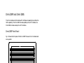
Elite 2864 Front Panel . . . . . . . . .
Elite 2864 Rear Panel . . . . . . . . .
Connecting the Elite 2864 . . . . . . .
Turning on the Elite 2864 . . . . . . . .
Elite 2864L . . . . . . . . . . . . . .
Elite 2864L Front Panel. . . . . . . . .
Elite 2864L Rear Panel . . . . . . . . .
Connecting the Elite 2864L . . . . . . .
Turning on the Elite 2864L . . . . . . .
Elite 2864I and Elite 2864IU . . . . . .
Supreme 2864L . . . . . . . . . . . .
Supreme 2864L Front Panel . . . . . .
Supreme 2864L Rear Panel. . . . . . .
Connecting the Supreme 2864L . . . . .
Turning on the Supreme 2864L . . . . .
Supreme 2864I and 2864IU . . . . . .
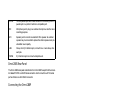
Omni 288P and Omni 288S . . . . . .
Omni 288P Front Panel. . . . . . . . .
Omni 288S Front Panel. . . . . . . . .
Omni 288P Rear Panel . . . . . . . . .
Omni 288S Rear Panel . . . . . . . . .
Connecting the Omni 288P . . . . . . .
Connecting the Omni 288S . . . . . . .
Turning on the Omni 288P or Omni 288S
.
.
.
.
.
.
.
.
.
.
.
.
.
.
.
.
.
.
.
.
.
.
.
.
.
.
TOC-2
.
.
.
.
.
.
.
.
.
.
.
.
.
.
.
.
.
.
.
.
.
.
.
.
.
.
.
.
.
.
.
.
.
.
.
.
.
.
.
.
.
.
.
.
.
.
.
.
.
.
.
.
.
.
.
.
.
.
.
.
.
.
.
.
.
.
.
.
.
.
.
.
.
.
.
.
.
.
.
.
.
.
.
.
.
.
.
.
.
.
.
.
.
.
.
.
.
.
.
.
.
.
.
.
.
.
.
.
.
.
.
.
.
.
.
.
.
.
.
.
.
.
.
.
.
.
.
.
.
.
.
.
.
.
.
.
.
.
.
.
.
.
.
.
.
.
.
.
.
.
.
.
.
.
.
.
.
.
.
.
.
.
.
.
.
.
.
.
.
.
.
.
.
.
.
.
.
.
.
.
.
.
.
.
.
.
.
.
.
.
.
.
.
.
.
.
.
.
.
.
.
.
.
.
.
.
.
.
.
.
.
.
.
.
.
.
.
.
.
.
.
.
.
.
.
.
.
.
.
.
.
.
.
.
.
.
.
.
.
.
.
.
.
.
.
.
.
.
.
.
.
.
.
.
.
.
.
.
.
.
.
.
.
.
.
.
.
.
.
.
.
.
.
.
.
.
.
.
.
.
.
.
.
.
.
.
.
.
.
.
.
.
.
.
.
.
.
.
.
.
.
.
.
.
.
.
.
.
.
.
.
.
.
.
.
.
.
.
.
.
.
.
.
.
.
.
.
.
.
.
.
.
.
.
.
.
.
.
.
.
.
.
.
.
.
.
.
.
.
.
.
.
.
.
.
.
.
.
.
.
.
.
.
.
. 3-1
. 3-1
. 3-1
. 3-4
. 3-5
. 3-6
. 3-6
. 3-7
. 3-7
. 3-7
. 3-7
. 3-7
. 3-7
. 3-8
. 3-8
. 3-9
. 3-9
. 3-9
. 3-10
. 3-10
. 3-10
. 3-11
. 3-12
. 3-12
. 3-13
. 3-13
MODEM OPERATION
MODEM OPERATION
4-1
Parallel or Serial Port Operation. . . . .
PC Parallel Port Operation . . . . . . .
Parallel Port under Windows . . . . . .
Parallel Port under DOS . . . . . . . .
Parallel Port Speed Limit . . . . . . . .
ZyXEL Parallel Port Adapter . . . . . . .
Using the Microphone and Speaker Jacks
Non-volatile Memory. . . . . . . . . .
Firmware Update/Upgrade . . . . . . .
DRAM Upgrade . . . . . . . . . . . .
Resetting The Modem . . . . . . . . .
.
.
.
.
.
.
.
.
.
.
.
.
.
.
.
.
.
.
.
.
.
.
.
.
.
.
.
.
.
.
.
.
.
.
.
.
.
.
.
.
.
.
.
.
.
.
.
.
.
.
.
.
.
.
.
.
.
.
.
.
.
.
.
.
.
.
.
.
.
.
.
.
.
.
.
.
.
.
.
.
.
.
.
.
.
.
.
.
.
.
.
.
.
.
.
.
.
.
.
.
.
.
.
.
.
.
.
.
.
.
.
.
.
.
.
.
.
.
.
.
.
.
.
.
.
.
.
.
.
.
.
.
.
.
.
.
.
.
.
.
.
.
.
.
.
.
.
.
.
.
.
.
.
.
.
.
.
.
.
.
.
.
.
.
.
.
.
.
.
.
.
.
.
.
.
.
LCD Panel . . . . . . . . . . . . . . .
Panel Operation . . . . . . . . . . . . .
Menu Tree. . . . . . . . . . . . . . . .
LED Status Screen . . . . . . . . . . . .
Double Arrows on The Screen. . . . . . .
Dialing . . . . . . . . . . . . . . . . .
Dial Memory . . . . . . . . . . . . . .
Storing a Number . . . . . . . . . . . .
Dial Number . . . . . . . . . . . . . .
Manual Dial and the DATA/VOICE Switches
Repeat Last Dial . . . . . . . . . . . . .
Auto Answer . . . . . . . . . . . . . . .
Dialing Messages . . . . . . . . . . . .
Panel Lock . . . . . . . . . . . . . . .
.
.
.
.
.
.
.
.
.
.
.
.
.
.
.
.
.
.
.
.
.
.
.
.
.
.
.
.
.
.
.
.
.
.
.
.
.
.
.
.
.
.
.
.
.
.
.
.
.
.
.
.
.
.
.
.
.
.
.
.
.
.
.
.
.
.
.
.
.
.
.
.
.
.
.
.
.
.
.
.
.
.
.
.
.
.
.
.
.
.
.
.
.
.
.
.
.
.
.
.
.
.
.
.
.
.
.
.
.
.
.
.
.
.
.
.
.
.
.
.
.
.
.
.
.
.
.
.
.
.
.
.
.
.
.
.
.
.
.
.
.
.
.
.
.
.
.
.
.
.
.
.
.
.
.
.
.
.
.
.
.
.
.
.
.
.
.
.
.
.
.
.
.
.
.
.
.
.
.
.
.
.
.
.
.
.
.
.
.
.
.
.
.
.
.
.
.
.
.
.
.
.
.
.
.
.
.
.
.
.
2864 QUICK START
5-1
MODEM PARAMETER SETTINGS
Parameter Menu . . . . . . . . . .
Parameter Selection . . . . . . . .
Status Register Content Modification .
Menu Tree Elements . . . . . . . .
TERMINAL OPTIONS . . . . . . . .
MODEM OPTIONS . . . . . . . . .
ERROR CONTROL . . . . . . . . .
AUDIO OPTIONS . . . . . . . . . .
. 4-1
. 4-2
. 4-2
. 4-2
. 4-2
. 4-3
. 4-3
. 4-3
. 4-3
. 4-5
. 4-5
.
.
.
.
.
.
.
.
.
.
.
.
.
.
.
.
.
.
.
.
.
.
.
.
TOC-3
. 5-1
. 5-2
. 5-2
. 5-2
. 5-3
. 5-3
. 5-4
. 5-4
. 5-5
. 5-5
. 5-6
. 5-6
. 5-7
. 5-9
6-1
.
.
.
.
.
.
.
.
.
.
.
.
.
.
.
.
.
.
.
.
.
.
.
.
.
.
.
.
.
.
.
.
.
.
.
.
.
.
.
.
.
.
.
.
.
.
.
.
.
.
.
.
.
.
.
.
.
.
.
.
.
.
.
.
.
.
.
.
.
.
.
.
.
.
.
.
.
.
.
.
.
.
.
.
.
.
.
.
.
.
.
.
.
.
.
.
.
.
.
.
.
.
.
.
.
.
.
.
.
.
.
.
.
.
.
.
.
.
.
.
. 6-1
. 6-2
. 6-2
. 6-2
. 6-3
. 6-6
6-11
6-12
SETTINGS AND COMMANDS
PROFILES
Resetting from Profile .
Saving to Profile . . .
Profile Protection . . .
Resetting Profiles . . .
7-1
.
.
.
.
.
.
.
.
.
.
.
.
.
.
.
.
.
.
.
.
.
.
.
.
.
.
.
.
.
.
.
.
.
.
.
.
.
.
.
.
.
.
.
.
.
.
.
.
.
.
.
.
.
.
.
.
.
.
.
.
.
.
.
.
.
.
.
.
.
.
.
.
.
.
.
.
.
.
.
.
.
.
.
.
.
.
.
.
.
.
.
.
.
.
.
.
STATUS REGISTERS
.
.
.
.
7-6
7-7
7-7
7-8
8-1
Reading and Setting S-Registers . . . . . . . . . . . . . . . . . . . . . 8-1
S-Register Descriptions . . . . . . . . . . . . . . . . . . . . . . . . . 8-3
ZyXEL-specific Registers. . . . . . . . . . . . . . . . . . . . . . . . . 8-5
AT COMMAND SET SUMMARY
9-1
Basic AT Command Set . . . . . . . . . . . . . . . . . . . . . . . . . 9-1
Extended AT& Command Set . . . . . . . . . . . . . . . . . . . . . . 9-6
Extended AT* Command Set . . . . . . . . . . . . . . . . . . . . . . 9-10
SPECIAL FUNCTIONS
ERROR CONTROL AND DATA COMPRESSION
Error Control . . . . . . . . . .
Data Compression . . . . . . .
Run-length Encoding . . . . . .
Adaptive Frequency Encoding . .
String Coding . . . . . . . . .
Bidirectional Compression. . . .
Negotiation Fail Fall-Back . . . .
DTE to DCE Connection . . . . .
Averaging Throughput . . . . .
Hints for High-speed Operation .
Flow Control . . . . . . . . . .
Hardware CTS/RTS Flow Control .
Software XON/XOFF Flow Control
.
.
.
.
.
.
.
.
.
.
.
.
.
.
.
.
.
.
.
.
.
.
.
.
.
.
.
.
.
.
.
.
.
.
.
.
.
.
.
.
.
.
.
.
.
.
.
.
.
.
.
.
.
.
.
.
.
.
.
.
.
.
.
.
.
.
.
.
.
.
.
.
.
.
.
.
.
.
.
.
.
.
.
.
.
.
.
.
.
.
.
.
.
.
.
.
.
.
.
.
.
.
.
.
.
.
.
.
.
.
.
.
.
.
.
.
.
.
.
.
.
.
.
.
.
.
.
.
.
.
.
.
.
.
.
.
.
.
.
.
.
.
.
.
.
.
.
.
.
.
.
.
.
.
.
.
.
.
.
.
.
.
.
.
.
.
.
.
.
.
.
.
.
.
.
.
.
.
.
.
.
.
10-1
.
.
.
.
.
.
.
.
.
.
.
.
.
.
.
.
.
.
.
.
.
.
.
.
.
.
.
.
.
.
.
.
.
.
.
.
.
.
.
.
.
.
.
.
.
.
.
.
.
.
.
.
.
.
.
.
.
.
.
.
.
.
.
.
.
SYNCHRONOUS OPERATION
Clock Options . . . . . . . . . . . . . . . . . . . . .
RTS Options . . . . . . . . . . . . . . . . . . . . . .
Half-Duplex Operation . . . . . . . . . . . . . . . . .
Mode Options . . . . . . . . . . . . . . . . . . . . .
Dial from Synchronous Mode . . . . . . . . . . . . . .
Auto-answer from Synchronous Mode . . . . . . . . . .
Manual Answer from Synchronous Mode . . . . . . . . .
Change from Synchronous Mode into Asynchronous Mode
Setting up a ZyXEL Modem with the AS-400 . . . . . . .
TOC-4
. 10-1
. 10-2
. 10-3
. 10-3
. 10-3
. 10-4
. 10-4
. 10-4
. 10-4
. 10-5
. 10-5
. 10-5
. 10-5
11-1
.
.
.
.
.
.
.
.
.
.
.
.
.
.
.
.
.
.
.
.
.
.
.
.
.
.
.
.
.
.
.
.
.
.
.
.
.
.
.
.
.
.
.
.
.
.
.
.
.
.
.
.
.
.
.
.
.
.
.
.
.
.
.
. 11-1
. 11-1
. 11-2
. 11-2
. 11-2
. 11-3
. 11-3
. 11-3
. 11-3
LEASED-LINE OPERATION
12-1
Connecting to a Leased Line . . . . . .
Line Type . . . . . . . . . . . . . . .
Power Level . . . . . . . . . . . . . .
Handshake Mode . . . . . . . . . . .
Manual Connection . . . . . . . . . .
Auto-handshake . . . . . . . . . . . .
Leased-Line Dial Backup . . . . . . . .
Dial Backup . . . . . . . . . . . . . .
Aborting from Leased-Line Operation . .
Disconnecting a Leased-Line Connection
.
.
.
.
.
.
.
.
.
.
.
.
.
.
.
.
.
.
.
.
.
.
.
.
.
.
.
.
.
.
.
.
.
.
.
.
.
.
.
.
.
.
.
.
.
.
.
.
.
.
.
.
.
.
.
.
.
.
.
.
.
.
.
.
.
.
.
.
.
.
.
.
.
.
.
.
.
.
.
.
.
.
.
.
.
.
.
.
.
.
.
.
.
.
.
.
.
.
.
.
.
.
.
.
.
.
.
.
.
.
.
.
.
.
.
.
.
.
.
.
.
.
.
.
.
.
.
.
.
.
.
.
.
.
.
.
.
.
.
.
.
.
.
.
.
.
.
.
.
.
.
.
.
.
.
.
.
.
.
.
.
.
.
.
.
.
.
.
.
.
.
.
.
.
.
.
.
.
.
.
.
.
.
.
.
.
.
.
.
.
.
.
.
.
.
.
.
.
.
.
.
.
.
.
.
.
.
.
.
.
.
.
.
.
.
.
.
.
.
.
.
.
.
.
.
.
.
.
.
.
.
.
.
.
.
.
.
.
.
.
.
.
.
.
.
.
.
.
.
.
.
.
.
.
.
.
.
.
.
.
.
.
.
.
.
.
.
.
.
.
.
.
.
.
.
.
.
.
.
.
.
.
.
.
.
.
.
.
SPECIAL FUNCTIONS
Security Function . . . . . .
Remote Configuration . . . .
Caller Number Delivery(CND).
Distinctive Ring . . . . . . .
Extended Distinctive Ring. . .
Setting Up The EDR . . . . .
Application Example . . . . .
V.25bis Command Set . . . .
12-1
12-1
12-2
12-2
12-2
12-2
12-3
12-3
12-4
12-4
13-1
.
.
.
.
.
.
.
.
.
.
.
.
.
.
.
.
.
.
.
.
.
.
.
.
.
.
.
.
.
.
.
.
.
.
.
.
.
.
.
.
CELLULAR MODE OPERATION
13-1
13-2
13-4
13-5
13-6
13-7
13-9
13-9
14-1
Cellular Phone Systems . . . . . . . . . .
Cellular Impairments . . . . . . . . . . . .
Cellular Modems and ZyCellular Technology .
ZyXEL ZyCellular Modes . . . . . . . . . .
Cellular Mode Usage . . . . . . . . . . . .
Cellular Modem Installation. . . . . . . . .
.
.
.
.
.
.
.
.
.
.
.
.
.
.
.
.
.
.
.
.
.
.
.
.
.
.
.
.
.
.
.
.
.
.
.
.
.
.
.
.
.
.
.
.
.
.
.
.
.
.
.
.
.
.
.
.
.
.
.
.
.
.
.
.
.
.
.
.
.
.
.
.
.
.
.
.
.
.
FAX OPERATION
.
.
.
.
.
.
14-1
14-1
14-2
14-3
14-3
14-4
15-1
ITU-T T.30 Fax Protocol . . . . . . . .
Fax Command Sets . . . . . . . . . .
Class 1 Command Set . . . . . . . . .
Class 2 Command Set . . . . . . . . .
Extended Fax AT Commands . . . . . .
Flow Control. . . . . . . . . . . . . .
Parallel Receiving with the Fax Machine .
Fax reception from within a BBS System .
Direct FAX Reception and Printing . . . .
Stand-alone FAX Reception and Storing .
.
.
.
.
.
.
.
.
.
.
TOC-5
.
.
.
.
.
.
.
.
.
.
.
.
.
.
.
.
.
.
.
.
.
.
.
.
.
.
.
.
.
.
.
.
.
.
.
.
.
.
.
.
.
.
.
.
.
.
.
.
.
.
.
.
.
.
.
.
.
.
.
.
.
.
.
.
.
.
.
.
.
.
.
.
.
.
.
.
.
.
.
.
.
.
.
.
.
.
.
.
.
.
.
.
.
.
.
.
.
.
.
.
.
.
.
.
.
.
.
.
.
.
.
.
.
.
.
.
.
.
.
.
.
.
.
.
.
.
.
.
.
.
.
.
.
.
.
.
.
.
.
.
. 15-1
. 15-2
. 15-2
. 15-3
15-13
15-16
15-17
15-17
15-18
15-20
ADVANCED VOICE CAPABILITY
16-1
Voice Data Compression . . . . . . . . . . . . . .
Automatic Detection of Voice, Fax and Data . . . . .
Voice States and Operation Modes . . . . . . . . . .
Voice Command State . . . . . . . . . . . . . . .
Voice Data State . . . . . . . . . . . . . . . . . .
Voice Data Transmission State. . . . . . . . . . . .
Voice Data Receival State . . . . . . . . . . . . . .
Events and Actions with Shielded Code. . . . . . . .
Event Detection and Reporting. . . . . . . . . . . .
Action Commands in Voice Data State . . . . . . . .
Voice AT Commands . . . . . . . . . . . . . . . .
Supported Commands For Voice Mode Operation . . .
Action Voice Commands for Voice Mode Operation . .
Configuration Commands for Voice Mode Operation. .
Examples of Voice Mode Operation . . . . . . . . .
Connecting a Telephone Set to the Modem's PHONE Jack
.
.
.
.
.
.
.
.
.
.
.
.
.
.
.
.
.
.
.
.
.
.
.
.
.
.
.
.
.
.
.
.
.
.
.
.
.
.
.
.
.
.
.
.
.
.
.
.
.
.
.
.
.
.
.
.
.
.
.
.
.
.
.
.
.
.
.
.
.
.
.
.
.
.
.
.
.
.
.
.
.
.
.
.
.
.
.
.
.
.
.
.
.
.
.
.
.
.
.
.
.
.
.
.
.
.
.
.
.
.
.
.
.
.
.
.
.
.
.
.
.
.
.
.
.
.
.
.
.
.
.
.
.
.
.
.
.
.
.
.
.
.
.
.
NETWORK MANAGEMENT CAPABILITY
ZyXEL Modem Network Management System .
Hierarchical Modem Network . . . . . . . .
Distributed Management . . . . . . . . . .
NMS Capable Models . . . . . . . . . . . .
.
.
.
.
.
.
.
.
.
.
.
.
.
.
.
.
. 16-1
. 16-2
. 16-2
. 16-3
. 16-4
. 16-4
. 16-4
. 16-5
. 16-5
. 16-7
. 16-8
. 16-9
16-12
16-14
16-20
16-27
17-1
.
.
.
.
.
.
.
.
.
.
.
.
.
.
.
.
.
.
.
.
.
.
.
.
.
.
.
.
.
.
.
.
.
.
.
.
DIAGNOSTICS
. 17-1
. 17-1
. 17-1
. 17-2
18-1
Power-on Self-test . . . . . . . . . . . . . .
Analog Loopback Test (AT&T1) . . . . . . . .
Analog Loopback with Self-test (AT&T8) . . . .
Local Digital Loopback Test (AT&T3) . . . . .
Remote Digital Loopback Test (AT&T6) . . . .
Remote Digital Loopback with Self-test (AT&T7)
Line Condition Status Display . . . . . . . . .
Link Status Report (ATI2) . . . . . . . . . . .
Throughput Display. . . . . . . . . . . . . .
Retransmission Indicator . . . . . . . . . . .
Dialing Indicator . . . . . . . . . . . . . . .
Handshaking And Retrain Indicator . . . . . .
Firmware Update . . . . . . . . . . . . . . .
TOC-6
.
.
.
.
.
.
.
.
.
.
.
.
.
.
.
.
.
.
.
.
.
.
.
.
.
.
.
.
.
.
.
.
.
.
.
.
.
.
.
.
.
.
.
.
.
.
.
.
.
.
.
.
.
.
.
.
.
.
.
.
.
.
.
.
.
.
.
.
.
.
.
.
.
.
.
.
.
.
.
.
.
.
.
.
.
.
.
.
.
.
.
.
.
.
.
.
.
.
.
.
.
.
.
.
.
.
.
.
.
.
.
.
.
.
.
.
.
.
.
.
.
.
.
.
.
.
.
.
.
.
.
.
.
.
.
.
.
.
.
.
.
.
.
.
.
.
.
.
.
.
.
.
.
.
.
.
. 18-1
. 18-2
. 18-3
. 18-3
. 18-4
. 18-4
. 18-5
. 18-7
18-10
18-10
18-10
18-10
18-10
HINTS AND TIPS
GENERAL HINTS AND TIPS
19-1
Activating Saved Settings upon Turning-on. . . . . . . . .
Avoiding Low Throughput and Loss of Data . . . . . . . .
Disabling Compression May Yield Faster Transfers . . . . .
Avoiding Disconnections during a Handshake on a Leased Line
Avoiding Disconnections when Making a Data Call . . . . .
Calling from an Extension / Blind Dial . . . . . . . . . . .
.
.
.
.
.
.
.
.
.
.
.
.
.
.
.
.
.
.
.
.
.
.
.
.
.
.
.
.
.
.
.
.
.
.
.
.
. 19-1
. 19-1
. 19-1
. 19-1
. 19-1
. 19-2
THE FIRST CONNECTION
20-1
ZyXEL MODEMS AND A PC
21-1
Serial Cable . . . . . . . . . . . . . . .
Parallel Cable . . . . . . . . . . . . . .
Using the Windows 3.1 Terminal Program.
Hardware Hints . . . . . . . . . . . . .
ZyXEL Serial/Parallel I/O Adapter Card . . .
.
.
.
.
.
.
.
.
.
.
.
.
.
.
.
.
.
.
.
.
.
.
.
.
.
.
.
.
.
.
.
.
.
.
.
.
.
.
.
.
.
.
.
.
.
.
.
.
.
.
.
.
.
.
.
.
.
.
.
.
.
.
.
.
.
.
.
.
.
.
ZyXEL MODEMS AND UNIX
Hints for Unix Setups .
Cable . . . . . . . .
Installation . . . . .
Software Tips . . . .
.
.
.
.
.
.
.
.
.
.
.
.
.
.
.
.
.
.
.
.
.
.
.
.
.
.
.
.
.
.
.
.
.
.
.
.
.
.
.
.
.
.
.
.
21-1
21-2
21-2
21-2
21-3
22-1
.
.
.
.
.
.
.
.
.
.
.
.
.
.
.
.
.
.
.
.
.
.
.
.
.
.
.
.
.
.
.
.
.
.
.
.
.
.
.
.
.
.
.
.
.
.
.
.
.
.
.
.
.
.
.
.
.
.
.
.
.
.
.
.
ZyXEL MODEMS AND APPLE MACINTOSH
Connector . . . . . . . . . . .
Apple Macintosh Particularities .
Cable . . . . . . . . . . . . .
Software for the Apple Macintosh
.
.
.
.
.
.
.
.
.
.
.
.
.
ZyXEL MODEMS AND ATARIS
.
.
.
.
.
.
.
.
.
.
.
.
.
.
.
.
.
.
.
.
.
.
.
.
.
.
.
.
.
.
.
.
22-1
22-1
22-1
22-2
23-1
.
.
.
.
.
.
.
.
.
.
.
.
.
.
.
.
.
.
.
.
.
.
.
.
.
.
.
.
.
.
.
.
23-1
23-1
23-2
23-3
24-1
Cable . . . . . . . . . . . . . . . . . . . . . . . . . . . . . . . . . 24-1
Hardware Tips . . . . . . . . . . . . . . . . . . . . . . . . . . . . . 24-2
Software Tips . . . . . . . . . . . . . . . . . . . . . . . . . . . . . 24-2
ZyXEL MODEMS AND AMIGA
25-1
Cable . . . . . . . . . . . . . . . . . . . . . . . . . . . . . . . . . 25-1
Software Tips . . . . . . . . . . . . . . . . . . . . . . . . . . . . . 25-2
Hardware Tips . . . . . . . . . . . . . . . . . . . . . . . . . . . . . 25-2
TOC-7
APPENDICES
GLOSSARY
EIA-232D INTERFACE
PHONE JACK PIN ASSIGNMENTS
ZyXEL PARALLEL PORT INTERFACE
V.25bis COMMAND SET
STANDARDS
GLO-1
A-1
B-1
C-1
D-1
E-1
ASCII Control Characters . . . . . . . . . . . . . . . . . . . . . . . . E-1
Selection of ITU-T standards . . . . . . . . . . . . . . . . . . . . . . . E-2
Data transmission through telephone networks (V.1 -V.110). . . . . . . . E-3
INDEX
Index-1
TOC-8
Chapter 1
INTRODUCTION
The 2864 series of V.34 modems includes three sub-series of models, namely the Supreme, Elite and Omni series. The Supreme and Elite series models have ISDN capability or can be upgraded to have ISDN capability. The Omni series does not have
ISDN capability. The Supreme series provides an LCD display panel while the Elite
series has a front panel with LED indicators only. Many features are common to all
three series. If not noted otherwise, a feature illustrated with one series model in this
manual applies to the other models and series as well.
The Elite 2864 series of high-speed modems features four base 10models. They differ only in the implemented line interface module, everything else is equivalent except for the panel LED indicator designations.
The models are
Model Name
Elite 2864
Elite 2864L
Elite 2864I
Elite 2864IU
Line Interface Module
Dial-up line DAA
Dial-up and leased line
DAA
ISDN S-interface
ISDN U-interface
Phone Line Used
Dial-up analog PSTN line
Dial-up and/or 2/4-wire leased analog line
ISDN line, S-interface
ISDN line, U-interface
The Elite 2864 has a 2-wire dial-up line DAA (Direct Access Arrangement) module
for connection to a normal PSTN (Public Switched Telephone Network) 2-wire
dial-up phone line. The Elite 2864L has a DAA with both a dial-up and leased line
interface. A 2 or a 4-wire leased line can also be used besides the normal 2-wire dialup line. Dial back-up capability is provided while using leased line. The Elite 2864I
has an ISDN S-interface module that will connect to an ISDN S-interface line. It
will connect to an ISDN call or a modem/fax call from PSTN made to this ISDN
line. A U-interface ISDN module is available for the USA market. The Elite 2864IU
is the ISDN model with the U-interface module.
By changing the line interface module, one Elite model will essentially become another Elite model. Each Elite model has different markings on its front and rear panels. Thus, in addition to the line interface module the front and rear panel also need
to be changed in order to transform one Elite model into a different Elite model.
Note that each Elite model has its own telecommunication authority approval
1–1
number. When the model is changed, the approval number is also changed. Find the
new approval number and check whether it is appropriate for the user to do the
model transformation before you start the transformation process.
Like the Elite series, the Supreme series includes different models which differ only
in the line interface module. There are three models in the Supreme series - The Supreme 2864L, 2864I, and 2864IU. The Supreme 2864L has a DAA with both a dialup and leased-line interface; the Supreme 2864I has an ISDN S-interface module;
the Supreme 2864IU has an ISDN U-interface module.
The Omni series models have only modem/fax/voice capability. They do not provide
ISDN capability nor are they ISDN upgradeable. The Omni 288P is the model with
a parallel port DTE interface and the Omni 288S is with a serial port DTE interface.
The Supreme and Elite models have both a parallel port and a serial port DTE interface.
How To Use This Manual
This manual describes the use of all models in the 2864 series and gives instruction
for their installation and operation. The 2864I and 2864IU ISDN models come
with a separate manual describing their ISDN operation.
The manual is divided into five sections.
Basic Overview - The first section is comprised of chapter 1 (INTRODUCTION)
through chapter 3 (MODEM INSTALLATION). It gives a basic overview of the
2864 series modems' features, introduces some basics of modem operation for novice users, and explains the installation of the different models of the 2864 series.
Modem Operation - The second section introduces you to some skills you will need
to make the best use of your modem. In chapter 4 (MODEM OPERATION) you are
introduced to the use of the different modem ports and you will find information
on how to return the modem to standard settings (reset) and how to upgrade your
modem in the future. The panel operation of the Supreme models is described in
chapter 5 (2864 QUICK START) and chapter 6 (MODEM PARAMETER SETTINGS). Users of the non-LCD models should consult the equivalent AT command
sections listed for each of the panel operations.
Settings and Commands - The third section, chapter 7 (PROFILES) through
chapter 9 (AT COMMAND SET SUMMARY), provides an overview of the settings
and commands which are available in the 2864 series.
Special Functions - Section four is comprised of chapter 10 (ERROR CONTROL
AND DATA COMPRESSION) through chapter 18 (DIAGNOSTICS) and describes
many special functions of the 2864 series modems in detail, including data compression, synchronous and leased-line operation, remote configuration, caller ID, cellu1–2
lar mode, fax sending and receiving, voice mail, network management, and
diagnostic features.
Hints and Tips - Section five is the trouble-shooting and special advice section. Here
you will find additional information on how to use a 2864 series modem with your
computer, and some hints and tips relating to a number of communication software
applications.
Appendices - An extensive glossary, several appendices with technical details, information on standards, and a thorough index complete this manual.
Those who need more detailed technical information may contact ZyXEL Communications Corporation directly. The address can be found in the disclaimer section at
the beginning of this manual.
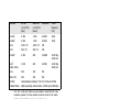
Compatibility
ZyXEL 2864 series modems are high performance universal modems capable of
transmission speeds up to 28.8 Kbps full-duplex on a 2-wire dial-up line. Universal
compatibility covers a broad range of ITU-T and BELL standards, and provides data
compression.
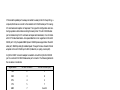
Various operation modes that can be achieved are as follows:
Standard
V.34
ZyXEL
ZyXEL
V.33*
V.33*
V.32bis
V.32bis
V.32bis
V.32
V.32 uncoded
V.32
V.29*
V.29*
V.29*
V.27bis*
Bit rate
(+/-0,01%)
[bps]
28 800 - 2 400
19 200
16 800
14 400
12 000
14 400
12 000
7 200
9 600
9 600
4 800
9 600
7 200
4 800
4 800
Baud rate
(+/-0,01%)
[baud]
multiple
2 743
2 400
2 400
2 400
2 400
2 400
2 400
2 400
2 400
2 400
2 400
2 400
2 400
1 600
1–3
Modulation
multiple
Carrier
frequency
[Hz]
multiple
128-TCM
64-TCM
128-TCM
64-TCM
16-TCM
32-TCM
16-QAM
4-DPSK
16-QAM
8-QAM
4-DPSK
8-PSK
1800
1800
1800
1800
1800
1800
1800
1800
1700
1700
1700
1800
Standard
V.27bis*
V.26bis*
V.23
V.23
V.22bis†
V.22†
(BELL 212A)
V.21
BELL 103
G3 FAX
Cellular Modes
Bit rate
(+/-0,01%)
[bps]
2 400
2 400
1200 / 75
600 / 75
2 400
Baud rate
(+/-0,01%)
[baud]
1 200
1 200
1200 / 75
600 / 75
600
Modulation
1 200
600
4-DPSK
4-DPSK
4-DPSK
FSK
FSK
16-QAM
Carrier
frequency
[Hz]
1800
1800
1200 Orig.
2400 Ans.
1200 Orig.
2400 Ans.
300
300
FSK
300
300
FSK
implemented according to T.30, V.17,V.29 and V.27ter.
ZyXEL proprietary cellular modes; 14400 bps to 4800 bps.
*. V33, V.29, V.27bis and V.26bis are only available in model 2864L for 4-wire
leased-line operation. The other operation modes are common to all models.
V.26bis works in half-duplex mode on 2-wire dial-up line.
†. 1800 Hz guard tone for V.22bis/V.22 answer mode, 6 dB below data signal level.
The 2864 Series Standard Features
• Synchronous/Asynchronous operations for external stand alone models and
rack mount models. (Parallel port interface is for asynchronous transmission
only)
• Asynchronous operations for PC internal card model.
• MNP class 4/5 error correction/data compression.
• V.42/V.42bis error correction/data compression. V.42 with selective reject.
• Extended AT command set.
• V.25bis async/sync command set.
• Operation on 2-wire dial-up line or 2/4-wire leased line. (4-wire leased line on
2864L only.)
• Auto-dial/answer and manual originate/answer.
• Tone/Pulse dialing.
• Dial tone, busy signal, and ringback detection.
• Programmable speaker volume control.
1–4
• Non-volatile memory for parameter/setting storage.
• Remote configuration.
• Security call back.
• Caller ID detection.
• Distinctive ring detection.
• Extensive status reports.
• Diagnostics available for:
•
Modem full self-test
•
Analog loopback (with self-test)
•
Remote digital loopback (with self-test)
•
Digital loopback
• XON/XOFF software and CTS/RTS hardware flow control.
• Line status monitoring available for (only Supreme 2864):
•
•
•
•
•
•
•
•
•
•
Signal-to-noise ratio
Received signal level
Frequency offset
Phase jitter
Retrain granted
Retrain requested
Round trip echo delay
Carrier loss counter
Rate change granted.
Rate change requested
•
Blocks retransmitted
•
Blocks received in error
• 20×2 LCD and directional keypads. (Supreme 2864 only)
• G3 Fax sending and receiving capability with speeds up to 14400 bps.
• Fax-Polling / Fax-Grouping.
• Automatic detection of data or fax call.
• Digitized voice capability with speech compression.
• DTMF tone detection.
• Special cellular modes for data communication through cellular link.
1–5
Additional specific features
ISDN Ready or Upgradeable
The 2864I model has an ISDN module to connect to an ISDN line. On the other
2864 models the phone line interface module may be removed and replaced instead
by an ISDN module to become an ISDN modem. The ISDN modem has both
ISDN capability and normal modem/fax/voice capability.
For ISDN capability, the 2864I supports a 2B+D ISDN basic rate interface. On the
B channel, the 2864I supports one B channel at 64Kbps or two B channels bundled
at 128Kbps. With data compression, the throughput is up to a few hundred Kbps.
The 2864I also supports one B channel for data and the other B channel for voice
communication. On the D channel, the 2864I supports 1TR6 protocol for German
ISDN, DSS1 protocol for Euro ISDN and NI1, AT&T 5ESS and Northern Telecom DMS-100 for North America ISDN.
A full feature analog port (a/b adapter) is provided. Thus, a regular telephone equipment may be connected to the ISDN line to make and receive ISDN calls through
this port. The metering pulse is also supported on this analog port for countries supporting it.
For modem/fax/voice capability, the 2864I can initiate and receive modem/fax calls
to/from a modem or fax machine connected to a PSTN analog telephone line. Voice
mail capability is also supported for voice calls to/from an ISDN or analog PSTN
line.
Voice Playback and Recording
A normal telephone set may be connected to the phone jack of the modem for local
voice message playback or recording. The modem provides the necessary DC voltage
and current for the telephone set to operate.
A microphone and a speaker jack are also provided for voice recording or playback.
An external microphone, speakers or a headset may be connected to the modem
through these jacks.
A large and good quality internal speaker is installed to provide better sound for
voice and music playback.
Telephony Capability
The 2864 series modem can detect the on/off-hook status or polarity change of the
phone line connection and the attached telephone set. These will be reported as
events in voice mode to the connected computer. The modem can also control and
switch between telephone connecting to line and modem connecting to line. It can
1–6
also control the switching between the phone line connecting to the modem and the
telephone set connecting to the modem. Both the modem and the telephone set may
also be connected to the line at the same time. A telephony software program can
utilize these capabilities to support various telephony functions.
Parallel and Serial Port Interface
The Supreme and Elite models have both a serial port and a parallel port. The Omni
model has either a serial or a parallel port. The serial port has a speed up to
460.8Kbps with auto speed detection (AT autobaud). The parallel port can connect
to either a PC's parallel port or a printer's parallel port. When it is connected to a
bidirectional PC parallel port, the PC can communicate with the modem through
the parallel port. The parallel port connection has the advantage that no data loss due
to overrun will occur and there is no serial port speed limit. When the modem's parallel port is connected to a laser printer with a Centronics type interface (the normal
PC to printer parallel interface), the modem can send received fax pages directly to
the printer without the need to start up a PC.
DRAM Expandability
8 Mbyte DRAM expandability is standard on the Supreme and Elite series modems.
Four DRAM sockets are provided on board to accept four 4M×4 16M DRAM
chips. The DRAM memory is useful for overnight stand-alone fax receiving. About
200 pages of normal fax can be stored without overflowing the DRAM memory. The
stored fax pages are available for later retrieval or printing.
Flash EPROM for Easy Firmware Update
With the versatile and feature rich hardware architecture, the 2864 series modems
are ready for firmware updates/upgrades for added and enhanced features. An 8
Mbit high-speed flash EPROM is standard on every 2864 modem (4 Mbit on Omni
models). A firmware update is only an AT command to upload a new firmware file.
It is not necessary to open the case or burn any EPROM.
Before You Start
Before you proceed further, please check the modem package and make sure nothing
is missing. The complete package should include:
1–7
• one (1) 2864 series universal modem
• one (1) power adapter (external model)
• one (1) RJ11 telephone cable
• one (1) JM8 leased-line cable (2864L model only)
one (1) RJ45 ISDN telephone cable (2864I model only)
• one (1) 2864 series user’s manual
• one (1) ZFAX 3.5" floppy disk and floppy disk(s) for drivers and other utilities.
• one (1) warranty/registration card
• one (1) Quick Reference Card
Contact your dealer or the store where you bought the modem if anything is missing. Check the modem for shipping damages. If you find any damage, contact the
shipping agency immediately.
Retain the shipping and cushioning materials for future storage or shipping needs.
Please direct any additional questions about damaged or missing materials to your
dealer or distributor, or to the factory address listed on your warranty card.
How To Become A Registered Owner
Fill in the registration card and mail it to the address found on the reverse side of the
card. Registered owners will receive future product and update information. You
don't have to register to receive warranty service. A dated invoice as proof of purchase along with the warranty card are sufficient.
What You Need To Have
You must provide the following additional equipment to operate your modem:
• A Computer/Terminal with communication software.
• A RS-232 serial cable or a 25-wire DB25 parallel cable (with one male and one
female connector).
• A telephone line from your telephone company (dial-up or leased line).
Communication Software
Communication software controls the modem connected to the computer and directs data to and from the modem. In most PC environments, the modem is used in
an asynchronous mode and the software controls the modem by AT commands.
1–8
ZyXEL modems support the extended AT command set and are compatible with
most communication software packages. However, there are some unique features in
the ZyXEL modem and there are a few unique commands to control them.
Some communication packages need a file with information about the commands
and features the modem supports. Basic information on how to set up communication software can be found in chapter 20 (THE FIRST CONNECTION). Information and sample data files for popular communication software packages are
available in the Application Driver Area of the ZyXEL BBS (+886-35-787045).
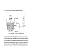
Connecting To Your Phone
If you would like to use a single phone line for voice and modem connections, remove your phone cable from the RJ11 junction box and plug one end of the RJ11
cable (supplied with the modem) into the phone junction box on the wall, then plug
the other end of the cable into the rear panel of the modem labeled DIAL-UP LINE
or WALL. Finish by plugging your phone cable into the rear panel of the modem labeled PHONE. Please refer to the illustrations in chapter 3 (MODEM INSTALLATION).
Dial-Up Or Leased Line
The 2864 and Omni 288 models may connect to 2-wire dial-up or leased lines only.
The 2864L offers you a choice of connecting to 2-wire dial-up lines (more commonly known as public lines) and 2/4-wire leased lines. To use the 2864L on a leased line,
you must order and install a USOC JM8 jack. You must also specify 4-wire operation without TEK leads for the wiring option. When setting up a pair of modems
for leased line point-to-point operation, one modem must be configured for originate mode and the other for answer mode. Both RJ11C and JM8 cables are supplied
for your convenience.
1–9
1–10
Chapter 2
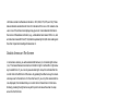
MODEM AND FAX BASICS
This chapter is intended for those readers who want to know the details behind modem and fax operations; what's going on behind the scenes. In addition to introducing basic modem and fax terminology, this chapter helps users to understand and be
able to utilize the available features. Experienced modem and fax users may wish to
skip this chapter.
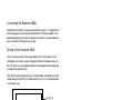
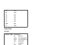
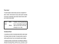
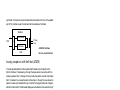
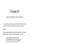
Modem
Modem is a compound word of MOdulator and DEModulator. A modem is used
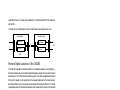
for computer communications. Refer to Fig. 2.1 for a standard modem setup and
application.
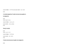
Modem
Modem
Fig. 2.1: Modems are used in computer communications.
A modem translates computer data to analog signals (modulation) that can travel
through the telephone network and reach another modem. The remote modem
translates the analog signal received back into data (demodulation) and sends the information to the receiving-end computer. Modems are telephones for computers,
what they use to talk to each other.
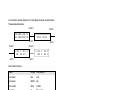
DTE and DCE
DTE and DCE are terminologies used in data communication. DTE stands for
Data Terminal Equipment and DCE stands for Data Circuit terminating Equipment (Data Communication Equipment). Referring to Fig. 2.1, the computer or
terminal is the DTE and the modem is the DCE.
2–1
RS-232C or EIA-232D/E
RS-232C is the Recommended Standard (RS) of the Electronic Industries Association (EIA), defining the serial communication interface between a DTE and a DCE.
The 232 is basically a serial number for the defined standard. Sometimes it is necessary to redefine a standard, or to revise it. The most commonly used revision of the
RS-232 standard is the "C" revision. For the "D" revision, the prefix was changed to
EIA. Except for a few added, but not commonly used signals, there is no practical
difference between the "C" and "D" revisions. There is now a new revision with the
”E“ suffix. The RS-232C standard is equivalent to the ITU-T V.24 and V.28 standard. Also refer to the Modem Standards and Speeds section below.
Serial Port
A serial port is the serial data connector together with its internal circuit on the DTE
or DCE with electrical and mechanical characteristics according to RS-232C. Since
some signals are going from the DTE port to DCE port, and some signals are going
in the other direction, the signal pin is a transmitter on one port and a receiver on
the other. The DTE serial port is different from the DCE serial port in terms of signals on the connector pins. There are also mechanical differences in terms of male
(with pins) or female (with holes) connectors.
Serial RS-232C Cable
A serial RS-232C cable is used to connect a DTE port to a DCE port. Do not use a
null-modem cable (which may be used to connect two DTEs directly with each other through their serial ports). A normal RS-232C connector has 25 pins and a normal RS-232C cable has 25 wires. Many signals in the RS-232C are not used in
common applications and a 9-wire RS-232C cable is sufficient in most applications.
The PC-AT's serial port has only 9 connector pins, eliminating the unnecessary pins.
For high-speed DTE-DCE comunication, use a low-capacitance cable, as short as
possible.
Synchronous and Asynchronous Communication
There are two kinds of serial data communication. One is called synchronous and
the other is called asynchronous. In synchronous communication, data is transmitted and received bit by bit and is timed by an accompanying clock signal. In asynchronous communication, data is sent character by character (or octet by octet), and
the idle time between characters is variable. No clock signal is sent; character timing
is recovered from the data itself.
2–2
A PC's COM1 and COM2 are asynchronous serial ports. Most PCs' and Unix systems' serial data communications are asynchronous. The serial data communication
on an IBM mainframe or mini is synchronous.
UART
A UART (Universal Asynchronous Receiver Transmitter) is the device used in a DTE
or DCE for asynchronous data reception and transmission. The standard UART device used in PCs is of the NS16450 type. For high-speed serial data transfers (38400
bps and up), the PC may not serve the UART fast enough and data may get lost. In
this case, a UART with data buffer is needed, such as the NS16550A type device.
Modem Standards and Speeds
The ITU-T or ITU-TSS (International Telecommunications Union - Telecommunications Standardization Sector), is the international standard-making body for telecommunications. They draft recommendations. The recommendations they make
for modem applications have a "V" prefix and are called V-series recommendations.
The commonly used ITU-T modem standards for 2-wire dial-up line are:
Standard
V.34
V.32bis
V.32
V.22bis*
V.22
V.21
V.23
Speed (bps)
28 800 - 2 400
14 400 / 12 000 / 7 200
9 600 / 4 800
2 400 / 1 200
1 200
300
1 200 / 75
*. bis is the old French word for second.
In the USA, Bell Systems used to create de facto standards such as Bell 212A for
1200 bps modems and Bell 103 for 300 bps modems. Everyone follows the ITU-T
standards now for newer and higher-speed modems.
ZyXEL 2864 series modems support all the above mentioned modem standards and
are compatible with existing modems.
Type of Telephone Line
The commonly used phone service is a 2-wire dial-up line. There are only two wires
connecting the modem to the phone company's central office. The same two wires
are used for DC current feeding, ringing, dialing, on/off-hook monitoring, and sig2–3
nal transmission in both directions. This is the type of phone service most people
have in their home or office. Since the same two wires are used for both transmitting
and receiving signals, an echo of the transmitting signal will also be received and it
is the modem receiver's task to remove the echo before demodulation.
Leased-line phone service is also available from phone companies in a 4-wire form.
Here, both the transmitting and receiving signals each use a separate 2-wire pair and
thus no echo problem will result. Normally, no DC current feeding, ringing, or dialing function is provided on a leased line.
There is also the 2-wire leased line which is a permanent 2-wire connection.
Intelligent Modem
Formerly, modem functions, settings, and operations were simple and everything
was controlled by manual switches, either internal or external, or by wire-strapping
settings. No computer control was provided.
All of an intelligent modem’s functions, including dialing and answering, are controllable by the computer or terminal it is connected to by means of the same RS-232
serial interface used for data connection.
An intelligent modem operates in one of two states - the command state or the data
state. In command state, the modem interprets data received from the serial interface
as commands and sends back an action result in response. In data state, the modem
modulates the data received from the serial interface and sends the demodulated data
to the serial interface as received data. The user needs to know whether the modem
is in the command state or data state and how to switch it.
ISDN
The normal telephone network PSTN (Public Switched Telephone Network) transmits voice band analog signals from end to end. A modem is needed at each end to
transmit digital data. The digital telephone network ISDN (Integrated Services Digital Network) transmits digital data from end to end, thus no modem is needed to
transmit data. Instead, an ISDN telephone is needed at each end to translate voice
signals to and from digital data for ISDN digitized voice data transmission.
ISDN TA
ISDN has a digital interface at the customer site. An ISDN TA (Terminal Adapter)
will adapt the user terminal’s interface, usually an asynchronous or synchronous serial interface, to the ISDN digital interface, usually the S- or T-interface. With an
ISDN TA a user connects a computer/terminal to the ISDN telephone line in the
same way as he/she uses a modem to connect a computer/terminal to the PSTN telephone line.
2–4
BRI
BRI, Basic Rate Interface, is the ISDN service provided to a normal home or office.
It consists of 2B+D data channels. A D channel offers a speed of 16Kbps for signaling information transmission. Each B channel is for user data transmission at
64Kbps. Each B channel can be used independently for voice or data transmission.
A user can place two independent calls through a BRI interface simultaneously.
U- or S-Interface
ISDN signal transmission is digital from end to end. At every interface point there
is a specified signal format. Equipment at every interface point needs to have signal
transmission/reception conform to the specified signal format. At the customer site,
the interface point for terminating the ISDN line connection from the CO (Central
Office) is called the U-interface. A network terminator NT1 terminates the ISDN
U-interface and converts it to the S-interface for internal ISDN equipment connection. Non-ISDN capable equipment can use an ISDN TA to connect to the S-interface.
In North America, the NT1 U-interface device is the user’s responsibility. The user
can either install an NT1 to get the S-interface for internal ISDN equipment connections, or have an ISDN TA to directly adapt to the U-interface. In Europe, the
telephone company installs the NT1 U-interface device at the customer site. The
user only needs to have the ISDN TA to adapt to the S-interface.
AT Command Set
The AT command set is the industry de facto standard used to control a modem in
command state. It got its name from the fact that every command line has a prefix AT.
AT commands were first used in the Hayes Smartmodem and hence adopted by
other modem manufacturers and communication software writers. The original set
of AT commands such as dialing, answering, etc., is used by everyone and is standardized. The AT command set is extended by each modem manufacturer for control
of ever-increasing modem functions and capabilities. This extended or enhanced
command set is not standardized whatsoever.
The AT command set is used only with an asynchronous serial data interface. To
send an AT command to a modem the connected computer must be running a terminal software. ZyXEL has defined a set of extended AT commands to support
many of its unique functions and features.
2–5
V.25bis Command Set
V.25bis is a set of auto-dialing commands defined by the ITU-T. V.25bis supports
both synchronous and asynchronous data interfaces and is mainly used in Europe
and in IBM mainframe or mini-environments which use synchronous communication.
Error Correction
In synchronous data communication, data is checked and corrected in the host by
the so-called "link layer protocol" to ensure data integrity. Normally, no data checking is provided in the host for asynchronous data communication. However, file
transfer protocols which include error checking are available with asynchronous
hosts.
Nowadays, intelligent modems incorporate error correction protocols inside the modem for asynchronous data communication and it is transparent to the host. The
modem packs the asynchronous data characters into blocks. The data is transmitted
as synchronous data between the modems. The data blocks are error checked at the
remote end, and an erroneous block is retransmitted.
The commonly used error correction protocols are MNP and V.42 protocols.
Data Compression
Intelligent modems use redundancy removing methods to reduce the number of
data bits actually sent for asynchronous character transmission. The full character
data is recovered at the other end, thus the total throughput of the modem data
transmission is increased.
The data compression protocols commonly used by modems are MNP class 5 and
V.42bis. (See definitions below.)
Data compression works on redundancy removing and its efficiency is dependent on
both the compression algorithm and data statistics.
MNP Protocols
MNP (Microcom Network Protocol) is a set of protocols first introduced by Microcom, Inc., and later used by many modem manufacturers. It consists of many
classes. Classes 1 to 4 are for error correction, and class 5 is for data compression.
MNP class 1 and 2 are obsolete. Normally class 4 is used for error correction and it
uses class 3 internally.
MNP class 5 is a data compression protocol with a maximum efficiency of 2 to 1.
MNP-5 is used with MNP-4 for error correction.
2–6
V.42bis and V.42
V.42bis and V.42 are data compression and error correction standards set by the
ITU-T. V.42bis has a better data compression efficiency than MNP-5 and is a more
advanced compression scheme. V.42bis is used with V.42 for error correction.
Xmodem, Ymodem, and Zmodem
These are file transfer protocols. They do error checking and ensure data integrity of
the file transferred. Some variations of these protocols also appear, like Xmodem-1k,
Ymodem-G, etc.
The "G" types of protocols do not include error checking. They allow very high
throughput rates, but can be safely used only when the modems use MNP4 or V.42
error protocols and there is no speed overrun on the computer's serial port.
Whenever possible, we recommend the use of Zmodem for added security and high
flexibility. Consult your communications program manual for more information on
transfer protocols.
Fax and Facsimile
Fax is the abbreviation for facsimile. There are four major parts in a normal facsimile
machine, the scanner, encoding and decoding device, modem, and printer. Before a
page can be sent, it is first scanned, the bit-mapped data is encoded with data compression, and then it is transmitted across the phone line by an internal modem
module. The remote facsimile receives the data with its internal modem, decodes it
back to bit-mapped image data and prints it on paper.
Fax Card
A fax card is an internal plug-in card which must be specifically designed to fit into
your type of computer. It has the modem function of a facsimile machine. A computer loaded with fax software can send or receive faxes through a fax card. The computer is used as the input and output parts of a facsimile machine and the fax card is
used as the transmit/receive part and may also do the encoding/decoding function,
depending on the design. The computer controls and communicates with the fax
card through a set of proprietary hardware and software interfaces which are different for each fax card manufacturer.
2–7
Modem as a Fax
Modems can also be designed to include a fax transmitting and receiving function
similar to a fax card. Since the modem's interface with the computer is the standard
serial RS-232 interface, this interface is used for both modem and fax operations.
Since the data throughput of a serial RS-232 interface is limited, only compressed
fax image data should be carried through this serial interface. Fax image coding and
decoding must be done in the computer. Modem/Fax, also called faxmodem, can be
either an external stand-alone unit or a plug-in card. External stand-alone units can
be connected to any computer with a standard RS-232 serial port.
EIA Class 1 and Class 2/2.0 Fax Commands
The EIA class 1 and class 2 fax commands are a set of AT fax commands defined by
EIA/TIA (Telecommunications Industry Association) for controlling faxmodems from a
computer through the serial RS-232 interface. Faxmodems and fax software supporting
this standard will work together. Class 1 commands control the details of how the modem does on-line negotiation and control jobs whereas Class 2 commands allow the modem to do many negotiations automatically. The Class 1 command set is also called the
TIA-578 standard. Several revisions of the class 2 standard exist. Implementations conforming to different revisions may not work together. A formally approved version is the
Class 2.0 command set, also called the TIA-592 standard.
Autodetection of Fax or Data Call
Fax and data modems have different handshaking signal sequences at the beginning
of a call as specified by the ITU-T. It is possible to automatically detect whether an
incoming call is from a modem or a fax device by testing and recognizing its initial
handshaking sequence. A modem with this capability can make a computer process
both data and fax calls on the same phone line. An example is that a BBS (Bulletin
Board System) can also receive faxes. ZyXEL modems can automatically detect data
and fax calls. ZyXEL also includes a fax reception and printing program to allow a
BBS to receive faxes and print them out.
Caller ID
Normally called Caller Number Delivery (CND), this is a service available from
phone companies in several parts of the USA and some other countries. With this
service, the phone company sends calling party information along with the ring signal to the called party. The major part of this information is the telephone number
of the calling party or caller ID. ZyXEL modems can detect and report caller ID.
Note that different countries have different caller ID schemes. Please check whether
the scheme used in your country is supported by the modem.
2–8
Distinctive Ring
This is a service available from some phone companies in some areas of the USA and
elsewhere. You can have several phone numbers on the same subscriber phone line.
The phone company sends a different ring signal for each phone number assigned
to the same line. You can have your phone equipment answer only a certain type of
ring corresponding to a certain phone number. ZyXEL modems can be set to answer
on one or a combination of four types of ring signals. The problem is that every
country may have a different specification for different ring types.
Digitized Voice
Modems with digitized voice capability can digitize an incoming voice message with
the computer storing it as a file. The modem can also playback a recorded digital
voice message either locally or to the line as an announcement.
Digital voice messages need speech compression to reduce the storage requirements.
This speech compression is done in real time by the modem and it does the decompression during playback. A simple voice capability using an ADPCM (Adaptive
Differential Pulse Code Modulation) algorithm can reduce the speech data rate to
1/2 or 1/3 of the original rate. An advanced algorithm is needed to reduce the speech
data rate even further.
Cellular Modem
A cellular modem is a data modem that can be used on the analog cellular mobile
phone system. With the rising popularity of notebook computers this is of increasing
importance for people on the move.
There are two kinds of phenomena in the cellular mobile phone system that are particularly bad for modem data communications. One is called cell hand-off, meaning
that a cellular phone is instructed to change the radio link from one cell site to another when travelling across a site boundary. The radio link will be temporarily interrupted and most modems will retrain or even hang up. When a cellular phone is
instructed by the cell site to change transmitting power, it will cause similar problems. The other particularly annoying phenomenon is multipath fading. Here, a
moving cellular phone will experience periodical fading or drop-out of the radio signal. This causes high data error rates and low throughput.
ZyXEL developed cellular modes using its proprietary data pump that handles the
cell hand-off and multipath problems. The V.42 link layer protocol with selective reject greatly improves data file transfer throughput in high error situations.
2–9
Automatic Redial / Call Hunting
Most modems will automatically redial a telephone number several times if a connection could not be established on the first try. The modems of the 2864 series also
offer the ability to do cyclic redials of a set of up to 10 different numbers.
Modem Approval and Legal Matters
In some countries the PTT authorities require modems to conform to a set of specific rules, e.g., transmitting signal level limitation, line circuit isolation, or restriction of the behavior of modems during automatic redial. Modems must receive an
official approval within those countries to be used legally. ZyXEL provides specifically designed models which have received such an approval. Check your local distributor to find out details about approved models.
2–10
Chapter 3
MODEM INSTALLATION
This chapter describes the panel function of the 2864 series modems and serves as
their installation guide.
External Modems
A shielded RS-232 cable is required to ensure compliance with FCC Part 15, and it
is the responsibility of the user to provide and use a shielded RS-232 cable.
Make sure your installation site is clean and well ventilated. The ventilation slots of
your ZyXEL modem located on the top, the sides, and the bottom should not be
covered and should allow free movement of air.
Elite 2864
The Elite 2864 model is a V.34 modem with V.34/fax/voice capability and is upgradeable to include ISDN capability. LEDs are used for all display purposes.
Elite 2864 Front Panel
Fig. 3.1 shows the front panel of the Elite 2864. There are 21 LED indicators and
two key switches.
Elite 2864
ZyXEL
D/V
V.34/FAX/VOICE
OH
More Than A Modem
PWR
TST
FAX
VO
SP
PRP
O/A
PCP
ORG
V34
V32b
AA
CD
DTR
POL
DSR
PSL
RTS
PPE
CTS
PER
TXD
RXD
EC
Fig. 3.1: The Elite 2864 front panel
3–1
V34
LED Indicators
PWR
TST
FAX
VO
SP *
PRP *
PCP *
Note:
OH
EC
SQ
ORG
V34
V32b
PoWeR on indicator; lights up when the modem‘s power is ON.
TeST indicator; lights up when the modem is in test mode.
FAX indicator; lights up when modem transmits or receives a fax.
VOice mode indicator; lit when modem is in voice mode.
Serial Port active indicator; lights up when modem is using the serial port for DTE communication.
PRinter Parallel port active indicator; lights up when modem is using the parallel port to drive a printer for fax printing.
PC Parallel port active indicator; lights up when modem is using the
parallel port to communicate with a PC's bidirectional parallel port.
*Only one of the SP, PRP, or PCP LED indicators will light up at one time.
Off-Hook indicator; lit when modem is on-line or in off-hook state.
It is turned off when modem is off-line or in on-hook state.
Error Control indicator; lights up when modem is operated in an error controlled mode like MNP4 or V.42. Data compression mode
(V.42bis or MNP5) implies error control mode. Also used as retransmission indicator; blinks when retransmitting.
Signal Quality indicator; lights up when signal quality is good;
flashes when it is on margin. At power on it flashes to indicate an
error condition; refer to the Diagnostics Chapter (18) for details.
ORiGinate mode indicator; when lit, the modem will operate in originate mode if it is manually made to go off-hook by toggling the
DATA/VOICE switch. If not lit, the modem will be in answer mode.
V.34 (or supported V.fast mode) indicator; flashes alternatively with
the V32b indicator when the modem is in a handshaking procedure.
V.32bis or V.32 mode indicator; flashes when dialing or before
handshaking.
The combinations of the V34 and V32b LEDs indicate the following modes:
V34
OFF
OFF
ON
ON
V32b
OFF
ON
OFF
ON
Mode
V.22bis, V.22 and other modes with speed less than 9600bps
V.32bis or V.32
V.34 (or supported V.fast mode, if any)
ZyX mode
3–2
AA
CD
TXD
RXD
Auto Answer indicator; lights up when the modem is in auto answer
mode; flashes when modem rings.
Carrier Detect indicator; lights up when a valid carrier is detected
present on the line.
Transmit Data indicator; lights up when your DTE/computer transmits data to the modem.
Receive Data indicator; lights up when your DTE/computer receives
data from the modem.
The following four indicators have different meanings depending on whether the
modem is connected to a DTE (computer or terminal) through either of the parallel
or serial interfaces (SP or PCP is ON, DTE mode) or whether the modem is connected to a printer through the parallel port interface (PRP is ON, printer mode).
DTR
POL
DSR
PSL
RTS
PPE
CTS
PER
DTE mode: Data Terminal Ready indicator; lights up when the DTE
or computer indicates that it is ready for communication by raising
the corresponding RS232 signal.
Printer mode: Printer On Line indicator; indicates the status of the
printer’s "Select" (SLCT) signal. It lights up when the printer is selected and is available for data transfer.
DTE mode: Data Set Ready indicator; lights up when modem is
ready for communication.
Printer mode: Printer SeLect signal; indicates the signal status of
"-Select In" from modem to printer. It lights up when printer is enabled to input data.
DTE mode: Request To Send indicator; indicates the signal status of
RS232 signal RTS from DTE. RTS is used for hardware flow control
in asynchronous data transmission.
Printer mode: Printer Paper End indicator; lights up when the printer is out of paper. It indicates the signal status of "PE" from the printer.
DTE mode: Clear To Send indicator; lights up when modem can accept data for transmission. It indicates the signal status of RS232
signal CTS.
Printer mode: Printer ERror indicator; lights up when an error condition exists in the printer, e.g., out ot paper or not on-line. It indicates the signal status of "-Error" from the printer.
3–3
Front Panel Switches
There are two toggle switches on the Elite 2864 front panel.
D/V (DATA/VOICE)
A toggle switch that switches the modem on-line (off-hook DATA mode) or off-line
(on-hook, Voice or Talk mode, the telephone set is connected to the line). The OH
LED indicator will be turned on and off by this switch. If S35 bit 4 is set
(S35.4=1), pressing this switch will make the modem go off-hook and dial the default number.
O/A (ORG/ANS)
A toggle switch that determines the mode, Originate or Answer, the modem will operate in, if made go off-hook by pressing the D/V switch. The ORG LED indicator
will be turned on and off by this switch.
Note:
This switch only determines modem operation mode if made go offhook manually. The ATD or ATA command will automatically determine the mode.
Warning:
If this switch is pressed while the modem is turned on, the modem
will jump into a special kernel program which allows the user to upload a new firmware into the modem from a connected DTE. If this
is not what you intended, turn off the modem and then turn it on
again to return the modem to normal operation.
Elite 2864 Rear Panel
Fig. 3.2 shows the Elite 2864 rear panel.
Parallel
POWER
JACK
DTE
Serial
LINE
Fig. 3.2: The Elite 2864 rear panel
3–4
PHONE
The following table explains the connectors on the rear panel:
POWER
JACK
PARALLEL
SERIAL
LINE
PHONE
Input terminal for power adapter. There is no power switch on the
modem.The power switch on the power adapter will turn off the
power adapter and shut off power to the modem. Always turn off the
power adapter before connecting or disconnecting power. For additional safety against possible damage, don’t turn on the power with
the parallel port connected to a piece of equipment which is under
power.
Parallel port DB25 male connector for connection to a PC's parallel
port or a printer's Centronics compatible port.
Serial port DB25 female connector for connection to the serial port
of a DTE (computer/terminal).
Dial-up line RJ11 terminal jack; for connection to a 2-wire dial-up
line on the wall jack.
RJ11 terminal jack; for connection to a telephone set.
Connecting the Elite 2864
Power Connection
Connect the power plug from the adapter to the power jack. Connect one end of the
power cord to the power adapter and plug the other end into an electrical outlet.
When you connect your 2864 to the power line, make sure you only use the ZyXEL
power adapter that is supplied with this unit. Use of another adapter may not allow
your modem to operate and could result in serious damage to the unit. This adapter
is rated for direct connection to an AC power outlet.
Turn off the power on both the computer and the modem before making connections. Then connect the modem according to the rear panel labels.
Warning:
Always turn off the power switch on the power adapter before connecting to the modem power jack. Never plug or unplug modem's
power jack with the power adapter turned on as this may damage
the modem.
Computer and Printer Connection
The modem has both a parallel port and a serial port connector. You can connect the
serial port connector to your computer's serial port or connect the parallel port connector to your PC's bidirectional parallel port or you can connect both ports to your
PC's serial and parallel port. You can also connect the serial port to your PC's serial
port, and the parallel port to a laser printer. If you have the modem set up for auto
3–5
Elite 2864L Front Panel
The Elite 2864L's front panel is exactly the same as the Elite 2864's except that the
Elite 2864L has an LL LED indicator instead of the VO indicator.
LL
Leased-Line indicator; lights up when the modem is operating in the
leased-line mode.
Elite 2864L Rear Panel
The Elite 2864L has a LEASED line jack and a DIAL-UP line jack. The LEASED
line jack is a JM8 leased-line connector for a 2 or 4-wire leased-line connection. Pin
assignments for the JM8 jack are listed in appendix B. Pins 1 and 2 are for 2-wire
leased-line connections. For 4-wire leased-line connections, pins 1 and 2 are for
transmission and pins 7 and 8 are for receiving. The DIAL-UP line connector is an
RJ11 connector for dial-up line connections. A normal telephone cable will connect
this jack to a telephone line wall jack. There is no PHONE jack for the Elite 2864L
model.
Connecting the Elite 2864L
Connect the power, serial port, and parallel port as described above for the Elite
2864 model. Connect the dial-up line to the DIAL-UP jack and the leased line to
the LEASED jack. If no leased line is used, just leave the jack unconnected.
Turning on the Elite 2864L
Please refer to Turning on the Elite 2864 on page 3–6.
Elite 2864I and Elite 2864IU
The Elite 2864I is the model with an ISDN S-interface RJ45 connector. The Elite
2864IU is the same model, but with an ISDN U-interface RJ45 connector. The basic panel description for the Elite 2864I and the Elite 2864IU is similar to that of
the Elite 2864. Please refer to the separate 2864I ISDN modem user’s manual for
details.
Supreme 2864L
The Supreme series model has a LCD display front panel. The Supreme 2864L supports 2/4-wire leased line in addition to the normal dial-up line support.
3–7
Supreme 2864L Front Panel
Fig. 3.3 shows the front panel of the Supreme 2864L. There are 10 LED indicators,
a 20×2 LCD display, and four directional key switches.
Fig. 3.3: The Supreme 2864L front panel
The 10 LED indicators are labeled as PWR, OH, AA, DTR/POL, RTS/PPE, TXD, RXD,
SP, PRP, and PCP. The meaning of these LED indicators can be found on page 3-2
to page 3-3 where the LED indicators of the same label are explained for the Elite
2864 model.
There are four arrow keys on the front panel for panel operations. They allow intuitive menu tree operation and status display. Please refer to chapter 5 (2864 QUICK
START) for details regarding the menu key operations.
Supreme 2864L Rear Panel
Fig. 3.3 shows the rear panel of the Supreme 2864L. The rear panel is similar to the
Elite 2864’s rear panel shown in , except that the Supreme 2864L has three phone
jacks. Besides the dial-up line RJ11 jack and the telephone connection RJ11 jack,
there is also a JM8 leased-line jack. Each rear panel connector’s explanation can be
found starting on page 3-4 where the explanations for the Elite 2864’s rear panel are
listed. The LEASE D LINE jack is a JM8 type jack with pin assignments listed in
appendix B.
Fig. 3.4: The Supreme 2864L rear panel
3–8
Connecting the Supreme 2864L
Please refer to the section Connecting the Elite 2864 on page 3–5. The descriptions
therein also apply to connecting the Supreme 2864L. The Supreme 2864L has an
additional leased-line jack for 2/4-wire leased line connection. Leave the leased-line
jack unconnected if the leased line is not used.
Turning on the Supreme 2864L
Turn on the power switch on the power adapter to turn on the modem. The Supreme 2864L will perform a series of diagnostic tests while a message is shown on
the LCD panel. For a more detailed description of these diagnostic tests, please refer
to chapter 18 (DIAGNOSTICS).
After performing the diagnostic tests, your Supreme 2864L will display the current
modem settings on the front LCD panel as shown in Fig. 3.3. Your Supreme 2864L
is now ready for use.
LINK OPTION
V34
28800
D R O A
V42b
DL
LINK SPEED
115200 AS
ERROR CONTROL
DATA FORMAT
LINE TYPE
DTE RATE
ANSWER MODE
ORIGINATE MODE
REDIAL LAST NUMBER
DIALING
Fig. 3.5: The Supreme 2864L idle screen after powering up
Supreme 2864I and 2864IU
The Supreme 2864I is the model with an ISDN S-interface RJ45 connector. The Supreme 2864IU is the same model, but with an ISDN U-interface RJ45 connector.
The basic panel description for the Supreme 2864I and 2864IU is similar to that of
the Supreme 2864L. Please refer to the separate 2864I ISDN modem user’s manual
for details.
3–9
Omni 288P and Omni 288S
The Omni models are V.34 modems with V.34/fax/voice capability, but without the
ISDN capability. The Omni 288P includes a parallel port as DTE interface, the
Omni 288S includes a serial port as DTE interface.
Omni 288P Front Panel
Fig. 3.3 shows the front panel of the Omni 288P. There are 13 LED indicators and
one key switch.
Fig. 3.6: The Omni 288P front panel
The 13 LED indicators are labeled as V34, V32b, AA, CD, TXD, RCD, DTR/POL,
DSR/PSL, PRP, PCP, EC, SQ, and OH. Explanations for the meanings of these LED
indicators can be found in the table beginning on page 3-2 where the LED indicators of the same label are explained for the Elite 2864 model.
There is only one push-button switch labeled D/V (DATA/VOICE) on the modem’s
upper case near the lower right corner. Please refer to the description on page 3-4 for
an explanation of the switch’s use.
Omni 288S Front Panel
Fig. 3.3 shows the front panel of the Omni 288S. Similar to the Omni 288P, there
are 13 LED indicators and one key switch. The LED indicators are labeled the same
3–10
as on the Omni 288P except that the Omni 288S has two LED indicators labeled
RTS and CTS instead of PRP and PCP as found on the Omni 288P.
Fig. 3.7The Omni 288S front panel
The meaning of the Omni 288S LED indicators can be found in the table beginning
on page 3-2 where the LED indicators of the same label are explained for the Elite
2864 model.
Omni 288P Rear Panel
Fig. 3.8 shows the rear panel of the Omni 288P.
Fig. 3.8: The Omni 288P rear panel
The table below explains the switch and connectors on the rear panel according to
their labels:
ON/OFF
POWER
AUX
RS232
The power switch; up position is ON, down position is OFF.
Input terminal for the power adapter, connects to an external AC or
DC 12V-16V, 1A adapter.
A RJ45 Jack for an auxiliary RS232 serial port; may be used to issue AT commands and receive responses for monitoring purposes.
3–11
TO DTE
MIC
SPK
LINE
PHONE
This is a parallel port DB25 male connector for connecting to a PC’s
parallel port or a printer’s Centronics compatible port.
Microphone jack to plug in an external microphone. Used for voice
recording purposes.
Speaker jack to connect an external 8 Ohm speaker. An external
speaker may be connected to replace the internal speaker and provide better sound quality.
Dial-up line RJ11 terminal jack; connects to a 2-wire dial-up line
wall jack.
RJ11 terminal jack to connect a telephone set.
Omni 288S Rear Panel
The Omni 288S’s rear panel is identical to the Omni 288P’s except that the connector labeled TO DTE is a DB25 female connector which connects to a DTE’s serial
port and there is no AUX RS232 connector.
Connecting the Omni 288P
Turn off the power on the computer (if possible) and the modem before making connections. Then connect the modem according to the rear panel labels.
Power connection
Use only the ZyXEL power adapter that is supplied with this modem. Using any other power adapter may cause serious damage to the modem and void warranty.
Connect the power cord from the power adapter to an AC electrical outlet and connect the round power plug from the adapter to the power jack on the modem. This
completes the power connection for the Omni 288P.
Warning:
Always turn off the power switch on the modem before connecting
the power adapter to the modem. Avoid plugging or unplugging the
modem's power jack with the power switch turned on as this may
damage the modem.
Computer and Printer Connection
The modem has a parallel port. You can connect this parallel port connector (labeled
TO DTE) to your PC's bidirectional parallel port for DTE communication. A normal
25-wire male to female shielded RS-232 cable can be used for this connection. You
can also connect the modem’s parallel port to a laser printer for direct fax reception
and printing operation. A normal PC printer cable together with a female DB25 to
female DB25 gender changer can be used for this connection.
3–12
If the modem’s parallel port is always connected to a laser printer for fax printing, a
computer/terminal can connect to the modem’s AUX RS232 serial port for issuing
AT commands and reception of responses. This is good for configuration and monitoring operation without disconnecting the laser printer. This AUX RS232 serial
port is intended only for AT command and response’s transmission; it is not intended for DTE data transmission. Auto speed detection is not supported on this AUX
RS232 port. Only the speeds 38400 bps and 19200 bps are supported on the AUX
serial port, 38400 bps being the default speed. The asynchronous character format
accepted on the AUX RS232 port is 8N1 (8 data bits, no parity, one stop bit).
A RJ45 to DB25F connector adapter is needed to convert the RJ45 AUX RS232
port to a normal DCE DB25 female serial port connector. The following table lists
the conversion connections:
Signal Name
TXD
RXD
RTS
CTS
GND
DSR, CD, DTR
Pin No. on DB25F
2
3
4
5
7
6, 8, 20 tied together
Pin No. on AUX RJ45
1
8
2
7
3 and 6
-
Phone Line Connection
Use the telephone cable supplied to connect the modem's LINE jack to the telephone line wall jack. You can also connect a telephone set to the modem's PHONE
jack in case you need the telephone for voice communication. A telephone set is not
needed for the modem's data, fax, and voice mail communication. The telephone set
may also be used to record or to playback voice messages.
Connecting the Omni 288S
Please refer to the above description for connecting the Omni 288P. The descriptions for
the power and phone line connection also apply to the Omni 288S. The descriptions for
connection to a computer or a printer through the parallel port do not apply, because the
Omni 288S has a serial port for connection to a computer/terminal’s serial port only.
There is no possibility to connect to a printer by parallel port.
Turning on the Omni 288P or Omni 288S
Turn on the power switch on the modem to turn on the modem. The modem will
do a self-test each time it is turned on. The SQ LED will flash if the power-on selftest fails. For a more detailed description of the diagnostic tests, please refer to
chapter 18 (DIAGNOSTICS).
3–13
3–14
Chapter 4
MODEM OPERATION
Parallel or Serial Port Operation
The 2864 models provide both a parallel port and a serial port for DTE connection,
but only one out of three connection modes may be active at any time. The available
modes are:
• SP: Serial port mode;
• PRP: Printer parallel port mode;
• PCP: PC parallel port mode.
Only when a port is actively driven and/or terminated externally may that port be
active, i.e., the connected device must be turned on and must drive the port. An exception to this is the serial port. The modem defaults to the serial port if no active
parallel port device is connected whether an active serial DTE is connected or not.
The modem makes its port selection based on the serial port DTR signal. If it is ON,
the modem defaults to serial port (SP) mode; if it is OFF, the modem seeks for an
active parallel port device. If an active PC parallel port is connected, the modem will
operate in PCP mode; if an active printer is connected, the modem will operate in
PRP mode. If no active parallel port device is connected, the modem will default to
SP mode.
If both the modem's serial and parallel ports are actively connected and the parallel
port is connected to a PC parallel port, the modem makes the port selection based
on the serial port DTR signal. The serial port DTE can control the modem's active
port through its DTR signal. If both the modem's serial port and parallel port are
actively connected and the parallel port is connected to a printer, the modem also
makes its port selection based on the serial port DTR signal. If the serial port DTR
signal is OFF, the modem operates in PRP mode; if the serial port DTR signal is
ON, the modem operates in SP mode. In Class Z mode operation for fax receiving
and printing(explained in chapter 15), the modem will temporarily switch to PRP
mode to print incoming faxes.
If you use a serial port DTE that does not provide a DTR signal, make sure that no
parallel port device is connected to the modem and that the modem defaults to serial
port mode. You also need to set the modem DTR setting permanently to ON (&D0).
4–1
PC Parallel Port Operation
If the modem's parallel port is connected to a PC's parallel port, the PC can communicate with the modem through the parallel port link. Be sure that your PC has
a bidirectional parallel port. The modem's parallel port will not work with the old
unidirectional parallel port. You need not have EPP nor ECP capability on your parallel port.
Using the parallel port, the PC sends and receives 8 data bits at a time to and from
the modem. However, for your communications software package the modem appears to be a serial device. A device driver has to be installed to shield the comm software from the actual difference in the hardware setup. The parallel port link accepts
hardware and/or software flow control, but setting the serial port speed is only a
dummy function; it has no effect on the parallel link.
The parallel port link only supports asynchronous mode communication. Synchronous mode is not supported. The modem buffers the data to and from the PC, direct
asynchronous mode is not supported.
Parallel Port under Windows
You need to install a driver in order to use your Windows comm or fax program.
ZyXEL has developed Windows parallel port drivers for which instructions are included on the program disk containing the drivers.
Parallel Port under DOS
When the DOS comm or fax program directly accesses the serial port, it is not possible for a driver program to intercept the access and redirect it to the parallel port.
However, the access can be redirected to the parallel port if a comm or fax program
accesses the serial port through a fossil driver, by changing the fossil driver. A fossil
driver is included on the companion software disk.
Parallel Port Speed Limit
Although there is no speed limitation on the parallel port data transfer similar to the
serial port, some parallel port I/O read/write operations need to be done for every
data byte transfer across the parallel port link. This limits the maximum parallel port
transfer speed. The operating system and/or the comm/fax program also does a lot
of overhead processing for data received or transmitted as well as for port maintenance. This also limits the maximum speed with which a PC can manage data passing through the parallel port. For the Windows user interface, or the DOS FOSSIL
driver, the latter is even a dominating factor. The good point about the parallel port
is that data overruns will never occur, no matter how slow the the software retrieves
data from the port. This is important in the Windows environment.
4–2
ZyXEL Parallel Port Adapter
ZyXEL is developing a special parallel port adapter that will make parallel port transfers much faster between a PC and the Elite 2864. The speed limitation in this case
will be determined by how fast and how efficient the PC software program can handle the data.
The operation instructions for this special parallel port adapter are included in the
adapter manual. Check ZyXEL's announcements for availability, which is expected
to be within a few months of the 2864's introduction. Refer to chapter 21 for information on the ZyXEL serial/parallel I/O adapter.
Using the Microphone and Speaker Jacks
On the right side or back of the modem, there are two jacks for external microphone
and speaker connections. The speaker jack is capable of directly driving an 8 ohm
speaker. When an external speaker is plugged into the speaker jack, the internal
speaker is cut off. The speaker jack only drives one speaker. If you have two speakers
with a stereo plug, use a plug adapter that will enable both speakers to be driven by
one source out of the speaker jack. If you are connecting the speaker jack output to
an amplifier, insert some attenuation in between. The speaker jack output signal may
be too strong for the amplifier.
The voice input/output device selection is controlled by voice AT commands. Use
AT+VLS=8 to select the external microphone and AT+VLS=16 to select the modem internal speaker as input or output device. The external speaker simply physically replaces the internal speaker, and the device selection remains the same.
Usually, the user makes input/output device selection through application software
packages according to the program's instructions and the user doesn't need to worry
about using commands to make a selection.
Non-volatile Memory
The Elite 2864 series modem uses a 16Kbit EEPROM for parameter storage, which
is four times larger than that of the U-1496 series. There are four user profiles of
which each includes 128 S-registers (S0 to S127). 50 phone numbers and 50 passwords can be stored.
4–3
Firmware Update/Upgrade
The 2864 series modem uses 4Mbit flash EPROM(s). The firmware in flash
EPROM can be updated by uploading a file from the locally connected DTE. There
is no need to open the modem case or use a programming device. The firmware is
distributed in a file with the following naming conventions:
E2864md.vvv
where
•
m is the model with value I, L, or nothing.
•
d is the D channel protocol for ISDN. Check the 2864I user's manual for
applicable values.
•
vvv is the version number.
The first letter is the denomination for the model, with E standing for Elite, S for
Supreme and B for an internal card model.
To update the firmware in a flash EPROM is called an "upload". You can run any
communications program on your computer that supports the X-modem file transfer protocol to upload. With the modem in command state, type in ATUPX and the
modem will ask for a confirmation. Answer yes and wait for the modem to respond
with the prompt:
Start programming, please upload....
Once the prompt appears, invoke the X-modem protocol to upload the file
E2864md.vvv to the modem which will update its flash EPROM with the
firmware contained in the uploaded file. If the upload is successful, the modem will
restart automatically.
If the upload fails, the modem may get stuck with its flash EPROM being erased.
Turn off the modem, and then press the O/A button while turning on the modem
again. Release the button a few seconds after turning on the modem. A kernel program will take control of the modem. The kernel is responsible for the firmware upload and update process and accepts a limited set of AT commands including the
ATUPX
4–4
For the Supreme models, pressing the MENU key (the UP arrow key) while turning
on the modem will have the modem execute the kernel program.
You can also use the ATUPA command to upload the firmware file. In this case you
can simply dump the firmware file to modem after typing the ATUPA command.
DRAM Upgrade
Open the modem's upper case. You will find four 26-pin sockets on the modem circuit board for 24-pin (26-pin size chip with 2 pins absent) 300 mil., SOJ package
DRAM chips. Four 4M×4 organisation 16Mbit DRAM chips may be inserted into
these sockets and that makes 8 Mbyte DRAM capability. ZyXEL is developing
firmware to accept two DRAM chips or one DRAM chip with DRAM sizes of
4Mbyte or 2Mbyte. If you install two DRAM chips for a 4Mbyte installation, install
them into the sockets labeled U38 and U39; for a 2Mbyte installation install one
chip into socket U27. The lower left corner of the DRAM sockets has a cut corner,
orient the DRAM chips correctly before inserting them into the sockets.
There are basically two types of 4Mx4 DRAM chips, one with 12 row and 10 column addresses and the other with 11 row and 11 column addresses. Both can be
used, but the former usually consumes less power. The important thing is to choose
the right chip package, some chips are of 400 mil width. An Example of acceptable
DRAM chips is TI TMS416400DJ. Both, -60ns and -70ns speed parts may be used.
Resetting The Modem
If you change the modem's setting and cannot get it back, or you just want to get
back to the factory default state, the following reset procedure will reset the modem
to the factory state. On the LED models, this procedure also causes the modem to
run a self-test. It is a good way to test the modem hardware.
On the LCD model, holding the ENTER key down for a few seconds while powering
up will reset the modem.
On the LED model, holding the DATA/VOICE key down for a few seconds (if you
own an Omni model, press for less than 10 seconds, otherwise the modem will go
to firmware update kernel execution) while powering up the modem will reset the
modem. The modem will also run a continuous analog loopback self-test. Printable
characters will be shown on the terminal connected to the modem's DTE port. The
V34, CD, DSR, CTS, RXD, EC, SQ, TST and PWR LEDs should be ON (The Omni
models do not have TST and PWR LEDs, and the parallel port Omni model, Omni
288P, does not have a CTS LED). If not, there is a hardware problem. Contact the
nearest service center for help. If SQ flashes, the number of flashes indicates the error
number corresponding to the error message listed at the beginning of chapter 18.
4–5
On the internal card model, short the TS2 jumper with a plug, then power up the
computer. The modem will be reset and will run a self-test. Printable characters will
be shown on the computer screen. The TS1 LED should be continuously ON. If the
LED flashes, the number of flashes indicates the error number corresponding to the
error message listed at the beginning of chapter 18.
This hardware reset procedure will reset the supervisor password back to the default
ZyXEL. But if you set S35.6=1 in profile 0, the supervisor password is protected
and not reset.
4–6
Chapter 5
Fig. 5.1
2864 QUICK START
Fig. 5.2
This chapter explains how to dial and answer using a modem. If you use this modem
with a PC, you probably don't need to worry about modem settings. The factory default should be just right for you. Connect the modem according to the instructions
in chapter 3, install the communication software, make the modem dial as instructed
in this chapter, and you're all set.
Furthermore, an introduction to the panel operation of the Supreme 2864L is presented. The Supreme 2864L comes with a menu driven 20×2 LCD display. All functions of the modem are displayed and selectable from this menu.
Finally, this chapter will familiarize the user with the menu tree structure. It properly
categorizes the modem operations. Non-LCD model modem users can also consult
the Supreme 2864L panel menu operations, but must use the equivalent AT commands listed in this chapter instead.
LCD Panel
The modem's actions, options, and parameters can be set, changed, and viewed from
the front panel, or viewed and changed through AT commands by the computer or
terminal connected to the modem. We will discuss panel operations in this chapter
with reference to equivalent AT commands. Note that in most cases you will use
your communication software to send AT commands to your modem. Only in very
rare circumstances will it be necessary to use the modem's panel.
Once turned on, the modem goes into the Idle Screen state (except if leased line is
selected). It then waits for commands from a computer/terminal or any key pad operation from the front panel. On the LCD screen, there are four on-screen buttons:
D
Dialing operation with submenus
R
Redial last number
O
Originate mode on-line
A
Answer mode on-line
5–1
The cursor is blinking above one of these on-screen buttons - a dark rectangle which
may be moved using the keys next to the display. The modem also displays the current status and settings in the idle screen:
Information
Example
V34
(V.34)
28800 (bps)
V42
(implied by V.42bis)
V42b (V.42bis)
DL
(Dial-up line)
AS
(asynchronous)
115200 (bps)
Link Option
Link Speed
Error Control
Data Compression
Line Type
Data Format
DTE Speed
Panel Operation
Use the four arrow keys to manipulate the menu tree.
Left/Right
arrow keys
Up arrow key
Down arrow key
used for horizontal item selection and option selection.
also called the MENU key, is used for vertical menu selection
and is used to access the previous menu. The up arrow key
also serves as a quit command when you want to stop the
current action.
also called the ENTER key, is used solely to register the chosen selection and is very similar to the Carriage Return key
or Enter key on a standard keyboard.
Menu Tree
Fig. 5.1 on the folded pages shows the menu tree structure. There are two main
menu trees. One is the CONFIGURATION menu, the other is the DIAGNOSTIC menu.
Fig. 5.2 shows the submenus under the CONFIGURATION menu. In Fig. 5.1, there is
one idle screen and four data state screens. In data state, screens (1) to (4) can be accessed by pressing the left or right arrow key. A dialing menu can be accessed from
the idle screen by activating the D on-screen button. Flip between idle screen and
menu screen by pressing the MENU or up arrow key.
LED Status Screen
Either in idle state or data state, there is an LED status screen that can be accessed
and displayed by pressing the left or right arrow key at the menu's top level. This
5–2
LED status screen has five status indicators - DCD, DSR, CTS, RTS, and SQ. These
status indicators are identical to the LED indicators of the non-LCD modems. Values in one of the other screen displays may give much more detailed information
than some of these status indicators; e.g., a data state screen means DCD is on, and
an idle screen means DCD is off; SQ is better explained by the S/N ratio reading and
the other impairment readings of data screen 2.
Double Arrows on The Screen
In some menu screens, you will see double left arrows (<<) or double right arrows
(>>). This means there are more items on the left or right. Use the left or right arrow
key to select them. If you can only see a double right arrow, this indicates that the
current item is the first item of the menu. By pressing the left arrow key, the screen
will wrap over to the last item. On the other hand, if you only find a double left arrow displayed, this indicates that your current item is the last item in that menu.
Similarly, pressing the right arrow key at this point will cause the screen to wrap
around to the first item.
Dialing
From the IDLE SCREEN (1) of Fig. 5.1 you can use the right or left arrow key to scroll
through D, R, O, and A. Move the blinking cursor to D, press ENTER, and you will
go into the Dialing Directory.
Valid digits/characters for dialing are:
0 1 2 3 4 5 6 7 8 9 * #
,
(Comma)
Pause
;
(Semicolon)
Return to command state
@
(at-character)
5 second silent wait
!
Hook flash
P
Pulse dial
R
Reverse dial
T
Tone dial
W
Wait for dial tone
–
(Dash)
Digit separator
←
(Backspace)
Backup one character and delete
5–3
Dial Memory
The first menu of the dialing directory is DIAL MEMORY. Pressing the ENTER key will
cause the following screen to appear:
#01: 1234567
<ENTER>
<< >> SELECT MEMORY
Dial out the number
Equivalent AT Commands
AT&Z?
View all stored phone numbers.
ATDSn
n = 0 - 49; dial stored number.
The first stored number shown on the menu is the default dial number which can
be selected from the DEFAULT DIAL menu. By pressing the left or right arrow key,
you can view up to 50 different numbers stored in the memory. Pressing the ENTER
key will cause the selected number to be dialed. The first line of the LCD can display
up to 16 characters. However, up to 25 characters can be entered. Characters 17
through 25 are displayed on the second line of the LCD display.
Storing a Number
Pressing the right arrow key from the DIAL MEMORY display will move the menu to
STORE NUMBER. Pressing the ENTER key at this point will produce the following
screen display:
<ENTER>
# 00:
<< >> SELECT MEMORY
# 00:
<< >> SELECT DIGIT
Changing an existing number
<ENTER>
# 00:1234567
<< >> SELECT MEMORY
# 00:
<< >> SELECT DIGIT
Equivalent AT Commands
AT&Z?
View all stored phone numbers.
AT&Zn=1234567 Store phone number in memory location n (n=0-49).
Just like DIAL MEMORY, up to 50 different numbers can be viewed and set. If you
want to add a number to the memory, select an unused memory location and press
5–4
ENTER. The blinking cursor will change into an underscore and will move to the next
position on the right side of the colon(:). SELECT MEMORY will change to SELECT
DIGIT. Press the left and right arrow keys to scroll through the valid digits and characters for dialing. Pressing ENTER will confirm the selected digit and cause the cursor
to move to the next position.
Repeat the above procedure to finish entering the number, then press ENTER again
to save the entry in the EEPROM. The stored numbers will remain in the memory
until you revise or delete them. Pressing the up arrow key in the process will abort
and exit the current number entry and nothing will be changed or saved.
Dial Number
The same procedure as in the STORE NUMBER operation is used when entering
numbers. Once the number entry is completed, press the ENTER key to dial the
number.
<ENTER>
<< >> SELECT DIGIT
1234567_
<< >> SELECT DIGIT
Dialing a number
Equivalent AT Commands
ATD1234567
Dial phone number.
Manual Dial and the DATA/VOICE Switches
Use of a telephone set to make a call, in which case an answer tone comes back, is
normally called Manual Dial. Once the other side answers, access the O(Originate)
by using the left or right arrow key so the blinking cursor settles on the O. Then press
the ENTER key to start the modem handshaking sequence.
Equivalent AT Commands
ATD
Go on-line in Originate mode.
When dialing a person, use the telephone to make the call. When someone on the
other side answers, decide who will be the Originate modem and who will be the
Answer modem. Once an agreement is reached, use the left or right arrow key to select the O or A for Originate or Answer. Then press the ENTER key to start the modem handshaking sequence.
Equivalent AT Commands
ATD
Go on-line in Originate mode.
ATA
Go on-line in Answer mode.
5–5
When you want to switch from modem to voice communication, simply lift up the
handsets of both sides and press the ENTER key while the blinking cursor is on the
H or Hang Up. The LCD display will show DISCONNECTING ? to ask for a confirmation. Press ENTER again and the modem will change from data to voice communication. When both sides wish to return to data communication, one side should
press O while the other side presses A (as explained previously). This operation will
reinitiate the modem handshaking and enable data communication.
For the non-LCD model, use the VOICE/DATA toggle switch for data/voice switching
and use the ORG/ANS switch to select originate mode or answer mode on-line. For
the Omni model, the AT*Mn command or S14b0 will decide originate or answer
mode on a manual connection. Whenever your modem establishes a connection
with another modem, one of the modems must be in answer mode and the other
modem in originate mode or a connection is not possible.
Equivalent AT Commands
+++
Escape sequence code; causes a modem to return to command
state. Enter the escape sequence while in data state and wait for the
modem to respond.
ATH
Go on-hook; disconnect the modem.
ATD
Go on-line in Originate mode.
ATA
Go on-line in Answer mode.
Repeat Last Dial
Access R (Repeat last dial) by pressing the left or right arrow key and the ENTER key.
Before a connection is made, any key pressed from the front panel or terminal keyboard will abort the redial operation.
Equivalent AT Commands
ATDL
Repeat last dial.
A/
Repeat last command once.
A>
Repeat last command once, retry the last call up to 9 times. (country specific)
Auto Answer
Move to the STATUS REGISTER menu, and change the S0 value to the desired
number of rings until the modem automatically answers. Setting this value to zero
disables auto answer.
Equivalent AT Commands
ATS0=0
Disable auto answer.
ATS0=n
Automatically answer on the nth ring.
5–6
Dialing Messages
Dialing will cause the following screen to be displayed on the LCD:
DIALING......................
1234567
The dialed phone number will be displayed on the second line of the 20×2 LCD
screen. If the number exceeds 20 digits, only the first 20 digits/characters will be displayed. If the modem's DIAL-UP LINE jack is not plugged in or not connected, the
LCD screen will display the following:
NO DIAL TONE..........
1234567
then the modem will go back to the IDLE STATUS screen. If the line is busy, after
three to five seconds, the LCD displays:
BUSY..............................
1234567
then goes back to the IDLE STATUS screen. If the phone company is ringing the remote modem, a RINGING message is sent to the terminal. Setting S42.6 = 1
will disable this RINGING result code. If any key interruption occurs (from the terminal or panel) and breaks in before the connection is made, the screen displays:
ABORT...........................
1234567
then goes back to the IDLE STATUS screen. If the time interval depicted in the S7
register expires, and the line is still not connected, the LCD screen shows:
DISCONNECTING.........
1234567
then goes back to the IDLE STATUS screen. If the first handshaking signal has been
detected, the LCD screen will display:
HANDSHAKING.............
1234567
5–7
If a connection has been made, the LCD will display the actual connected status.
These are data state screens:
<RIGHT>
V.34 28800 V42b DL
H>> 55820 51324 AS
<RIGHT>
<< SN= 30.9 RX=-25.1 >>
PJ= 0.4 FO=-0.0
<LEFT>
<LEFT>
<RIGHT>
<RIGHT>
<< RG= 0
RT= 0 >>
ED = 128 CL= 0
<LEFT>
<< FG= 0
BR= 0
FR= 0
FE= 0
<LEFT>
On-line Status Screen 1
Status
Link Option
Line Speed
Error control
Line Type
Data Format
Instant Transmission Throughput
Instant Receiving Throughput
Display
V34
28800
V42b
DL
AS
55820
51324
Unit/Meaning
V.34
bps
V.42bis
Dial-up Line
ASynchronous
bps; Blank in synchronous mode
bps; Link Speed in synchronous
mode
On-line Status Screen 2
Status
Signal to Noise ratio
Receiving Signal level
Phase Jitter in received signal
Frequency Offset in received signal
Display
30.9
-25.1
0.4
-0.0
Unit
dB
dBm
degrees
Hz
Display
0
0
128
0
Unit
On-line Status Screen 3
Status
Retrain Granted
Retrain requesTed
Round trip Echo Delay
Carrier Loss counts
5–8
T; 1/2400 s
On-line Status Screen 4
Status
FRN ( Fast Rate reNegotiation) Granted
FRN Requested
Blocks Retransmitted
FCS (Frame Check Sum) Errors
Display
0
0
0
0
Unit
Pressing the left or right arrow key in any one of the ON-LINE STATUS screens will
cause the LCD to scroll through the four screens. We will discuss the ON-LINE
STATUS screens 2, 3, and 4 in more detail in chapter 18.
Pressing the ENTER key while in any ON-LINE STATUS screen will cause the LCD to
display the following:
<ENTER>
DISCONNECT
YES
?
NO
DISCONNECTING.........
IDLE SCREEN (1)
Equivalent AT Commands
+++
Escape sequence code; causes the modem to return to command
mode. Enter escape sequence in the data state and wait for the modem to respond.
ATH
Go on-hook (hang up); disconnect the modem.
Pressing the up arrow key (MENU) or selecting NO will switch the screen back to the
ON-LINE STATUS screen 1 and the modem remains on-line. Pressing ENTER will
hang up the line and cause the modem to revert to the IDLE STATUS screen to await
your next command.
Pressing the up arrow key (MENU) in any of the four data state screens will change
your current screen to the CONFIGURATION menu. This will be discussed in
chapter 6.
Panel Lock
The panel keyboard can be locked to prevent inadvertent changes in modem settings. This is done by setting the S-register S28 bit 1 to 1 or using the PANEL LOCK
menu from the panel, or by issuing the AT*L1 command from the terminal. Issuing
the AT*L0 command will return the key operation to normal. Alternatively, pressing the left and right arrow keys simultaneously will unlock the panel. In locked panel mode, the ENTER key will lose its effectiveness in changing or saving settings; panel
command execution is also disabled. However, viewing in the panel is not affected.
5–9
5–10
Chapter 6
MODEM PARAMETER SETTINGS
This chapter explains how to view and set various major modem parameters using
the Supreme 2864L CONFIGURATION menu tree. The non-LCD model users can
also consult this menu tree for available parameter options, but must use the equivalent AT command to set the parameter.
The various levels of the CONFIGURATION menu tree are defined here as:
CONFIGURATION menu
submenus
parameter menus
parameter selection
whereby the CONFIGURATION menu is the root of this menu tree. Some submenus,
like STATUS REGISTER, SAVE TO, and RESET, have a direct parameter selection under them and do not have the parameter menu level.
Under the CONFIGURATION menu, there are seven submenus (see also Fig. 5.1):
•
TERMINAL OPTIONS (parameters for local DTE connection)
•
MODEM OPTIONS (parameters for connection to a remote DCE)
•
ERROR CONTROL (how to react to transmission errors)
•
AUDIO OPTIONS (controlling the internal speaker)
•
STATUS REGISTER (see chapter 8)
•
SAVE TO (saving a set of parameters into a profile)
•
RESET (loading a profile)
Every submenu screen defines certain parameters of the modem’s operation. Submenu selections are made by using the left and right arrow panel keys. Pressing the
ENTER key will access the parameter menu and pressing the up arrow key (MENU)
will return you to the CONFIGURATION menu.
Parameter Menu
The parameter menu selections are made by using the left and right arrow keys to
move from one selection to another. Pressing the up arrow key (MENU) will return
you to the submenu screen. Press ENTER to go into Parameter Selection. You will notice that a blinking cursor will appear at the left side of the equal sign (=).
6–1
Parameter Selection
Press the left or right arrow key to view and scroll the available parameters. Only the
parameters currently in effect have the equal sign (=) before their respective selections, otherwise a colon (:) appears, meaning that this parameter choice is a selectable option. By pressing MENU to quit the viewing, the screen will return to the
parameter menu and the parameter will remain unchanged. Press ENTER to avtivate
the selected parameter.
To save the current parameter settings to the non-volatile EEPROM, access the
SAVE TO submenu in the CONFIGURATION menu and select the profile you wish to
save the changes to from the various profiles offered. The parameter settings will then
be in that profile permanently. You can always recall these settings by resetting from
that profile. Access RESET and choose =FACTORY DEFAULT and the active parameter
settings will revert to the original factory defaults. Also, any S-register's contents can
be individually modified in the STATUS REGISTER submenu.
Status Register Content Modification
When you access the STATUS REGISTER submenu in the CONFIGURATION menu,
the blinking cursor will be changed into an underscore (_) and the contents will be
blanked out. Press the left or right arrow key to scroll through a series of hex digits,
then press ENTER when the desired digit appears. Remember that both digits must
be entered. Pressing the up arrow key (MENU) will quit the entry procedure. The
blinking cursor will reappear and the contents will remain unchanged.
Menu Tree Elements
In the rest of this chapter, we will explain the parameter selections of each parameter
menu and of each configuration submenu. The large boldface title of each section is the name of a configuration submenu under which each boldface subtitle is
the name of a parameter menu. Under each parameter menu, there are tabulated parameter items. These are the selectable parameter items in this parameter menu. On
the right of each parameter item is the equivalent AT command to select or set this
parameter. A brief explanation of each parameter follows. A plus sign (+) in front of
a parameter item denotes the default parameter setting.
6–2
TERMINAL OPTIONS
DATA FORMAT
+ ASYNC
AT&M0
SYNC DATA
AT&M1
DIRECT
AT&M2
SYNC
AT&M3
Operates as an asynchronous modem with
data buffering, may work with data compression and/or error control. Fixed DTE speed with
flow control. (Default)
The modem accepts asynchronous commands, but changes to synchronous operation
in data mode and exchanges data synchronously with a remote modem.
Direct asynchronous mode without data buffering. DTE speed equals link speed.
The modem accepts synchronous commands
(V.25bis) and exchanges data synchronously
with a remote modem. As an alternative, you
can dial from the front panel or use a telephone
set to connect.
DATA FORMAT defines the methods your modem employs to exchange data with the
local DTE and the remote DCE.
CHARACTER LENGTH
+
10
11
9
8
Note:
AT*C0
AT*C1
AT*C2
AT*C3
10-bit characters. (Default)
11-bit characters.
9-bit characters.
8-bit characters.
The character length includes the start, data, parity, and stop bit(s).
COMMAND SET
+ AT
AT*I0
V.25bis
AT*I1
DUMB
AT*I2
Note:
The modem accepts asynchronous AT commands. (Default)
The modem accepts asynchronous or bit-oriented synchronous V.25bis commands.
No commands will be accepted. The modem
ignores the DTE data in idle state.
Only asynchronous commands are accepted on the parallel port or
internal card DTE interface.
6–3
DTE RATE
+ FIXED
AT&B1
FOLLOWS
LINK RATE
Note:
AT&B0
Modem serial port speed is always fixed, no
matter what link rate (modem speed) is connected. If S44.6=1 and a non-ARQ connection is made, DTE rate follows link rate as if
&B0 were set. (Default)
Modem serial port speed is set in accordance
with the link rate. If S44.6=1, the DTE speed
is fixed at 38400 bps when the link speed is
above 9600, at 9600 when the link speed is
7200, and at link speed when it is below 7200.
If you wish to keep your DTE rate fixed, you should choose a buffered transfer. (see DATA FORMAT)
DTR OPTIONS
IGNORED
AT&D0
108.1
AT&D1
+ DTR / 108.2
AT&D2
108.2 + RST
AT&D3
Note:
The modem assumes that DTR is always ON
and ignores the DTR signal on the serial port.
An OFF-ON DTR transition causes the modem to
dial the number specified under the DEFAULT
DIAL of the MODEM OPTIONS submenu. An
ON-OFF transition disconnects the modem from
the line.
An ON-OFF transition of the DTR signal will disconnect the modem from the line. (Default)
Same as &D2 but DTR OFF also causes reset
from profile 0.
Not all computers provide a DTR signal at their serial port connector.
If this is true for your computer (e.g., Apple Macintosh), you must
use the IGNORED setting (AT&D0).
DCD OPTIONS
+ TRACKS
CARRIER
ALWAYS ON
AT&C1
AT&C0
DCD ON when a carrier is detected (see also
S38b3). If S42.7=1, DCD only pulses off for
0.5 sec when carrier loss occurs. (Default)
The modem forces DCD to always remain ON.
6–4
RTS OPTIONS
+ IGNORED
AT&R1
CTS TRACKS
RTS
Note:
AT&R0
The modem assumes that RTS is always ON
and ignores the serial port signals. (Default)
Delay before CTS responds to RTS's change.
The delay is set in S26.
Effective only in synchronous mode. This setting is ignored in asynchronous mode. RTS is always used as a hardware flow control signal in this case.
DSR OPTIONS
+ ALWAYS ON
AT&S0
DATA SET
READY
AT&S1
The modem forces DSR to always remain ON.
(Default)
According to ITU-T. DSR ON during handshake.
If S41.5=1, DSR follows CD, and pulses off for
0.5 sec for CD on-off transition. If S44.4=1,
DSR follows DTR.
COMMAND ECHO
+ ENABLED
DISABLED
ATE1
ATE0
The modem echoes commands. (Default)
The modem does not echo commands.
ATQ0
ATQ1
ATQ2
The modem returns result codes. (Default)
The modem does not return result codes.
If S40.1=1, the modem does not return result
codes in answer mode.
RESULT CODE
+ ENABLED
DISABLED
DTE ASYNC SPEED
230400
115200
76800
57600
38400
19200
16800
14400
Selects DTE port asynchronous serial speed. AT
command auto speed detection will override
this selection.
307200
153600
102400
61400
51200
6–5
12000
9600
7200
4800
2400
1200
460800
300
624000
124800
62400
41600
31200
24960
20800
921600
MODEM OPTIONS
LINK OPTIONS
+ MULTI-AUTO
AT&N0
Auto handshaking with
28800 to 2400
V.34
ZyX19200
ZyX16800
V.32bis
V.32
V.22bis
V.22
BELL212A
G3 Fax
19200 (Disabled wth S43.1=1)
16800 (Disabled with S43.0=1)
14400/12000/7200
9600T/9600/4800
2400/1200
1200
1200
14400 /12000/9600/7200/
4800/2400 (V.17, V.29, V.27ter)
(To turn fax reception off:
S38.4=1)
Cellular Modes 14400 to 4800
(Enabled with S43.3=0).
V.33 14400
V.33 12000
V.32 9600T
V.32 9600
V.32 4800
V.29 9600
V.29 7200
V.29 4800
V.27b 4800
V.27b 2400
V.26b 2400
V.23 1200
V.23 600
AT&N1
AT&N2
AT&N3
AT&N4
AT&N5
AT&N6
AT&N7
AT&N8
AT&N9
AT&N10
AT&N11
AT&N12
AT&N13
V.33
V.33
V.32
V.32
V.32
V.29
V.29
V.29
V.27bis
V.27bis
V.26bis
V.23
V.23
6–6
14400/12000
12000
9600T/9600/7200T/4800
9600(non-trellis coded)/7200T/4800
4800
9600
7200
4800
4800
2400
2400
1200/75
600/75
V.22b 2400
V.22 1200
V.21 300
V.32b 14400
V.32b 12000
V.32b 7200
B212A 1200
B103 300
V17 G3 FAX
AT&N14
AT&N15
AT&N16
AT&N17
AT&N18
AT&N19
AT&N24
AT&N25
AT&N32
V.22bis
V.22
V.21
V.32bis
V.32bis
V.32bis
BELL 212A
BELL 103
ZyXEL FAX
2400/1200
1200
300
14400/12000/9600/7200/4800
12000/9600/7200/4800
7200/4800
1200
300
14400/12000/9600/7200/
4800/2400
Set S42.4=1 to disable V.17 in calling mode.
ZyX 19200
ZyX 16800
ZyX 14400
ZyX 12000
ZyX 9600
ZyX 7200
CELL 14400
CELL 12000
CELL 9600
CELL 7200
CELL 4800T
V.34 28800
V.34 26400
V.34 24000
V.34 21600
V.34 19200
V.34 16800
V.34 14400
V.34 12000
V.34 9600
V.34 7200
V.34 4800
V.34 2400
AT&N34
AT&N35
AT&N36
AT&N37
AT&N38
AT&N39
AT&N42
AT&N43
AT&N44
AT&N45
AT&N46
AT&N62
AT&N63
AT&N64
AT&N65
AT&N66
AT&N67
AT&N68
AT&N69
AT&N70
AT&N71
AT&N72
AT&N73
ZyXEL
ZyXEL
ZyXEL
ZyXEL
ZyXEL
ZyXEL
CELL
CELL
CELL
CELL
CELL
V.34
V.34
V.34
V.34
V.34
V.34
V.34
V.34
V.34
V.34
V.34
V.34
6–7
19200
16800
14400
12000
9600
7200
14400
12000
9600
7200
4800T
28800
26400
24000
21600
19200
16800
14400
12000
9600
7200
4800
2400
QUALITY ACTION
AUTO RETRAIN
AT*Q1
+ ADAPTIVE
RATE
AT*Q2
DISCONNECT
AT*Q3
NORESPONSE AT*Q0
Retrains automatically when poor signal quality
is detected. S41.2=1 extends retrain time out
to 5 minutes.
Falls back automatically to next lower speed
when poor signal quality is detected. Falls forward automatically to the next higher speed
when the signal quality is improved. (Default)
When poor signal quality is detected, the modem disconnects itself.
No response to poor signal quality.
DEFAULT DIAL
PH0 - PH49
AT*D0
...
AT*D49
Default dial pointer. This will be the first phone
number displayed in the DIAL MEMORY menu
(default: PH0). If the DTR option 108.1 is active, a DTR OFF-ON transition causes the modem to dial the number stored in the memory
address selected (memory address 0 to 49).
(See also S35b4)
AT*B0
AT*B1
...
AT*B50
Leased line dial backup disabled. (Default)
When a leased-line cannot continue operation,
the originate mode modem will automatically
dial the number stored in the memory address
selected. The answer mode modem also needs
to select a non-zero memory address to enable
answering at the dial-up line during dial backup. (See also S44b2)
DIAL BACKUP
+ DISABLED
PH0 - PH49
GUARD TONE
(For V.22 and V.22bis answer mode operation).
+ NONE
RESERVED
1800 Hz
AT&G0
AT&G1
AT&G2
No guard tone provided. (Default)
Reserved.
1800 Hz guard tone provided.
6–8
RDL REQUEST
GRANT
AT&T4
+ DENY
AT&T5
Accepts remote digital loopback test request
from remote modem. Must be set when remote
configuration is needed.
Ignores remote digital loopback test request
from remote modem. (Default)
LLINE TX POWER (Leased LINE)
0 to -15 dBm
AT*P0
...
AT*P15
Selects transmission power from 0 dBm to -15
dBm. Default is -9 dBm. Effective in leased-line
operation only. Select in the range of -12 to -27
dBm when S35b3 is set. The Omni 288P and
288S have a maximum TX power of -9dBm
and -3dBm, respectively.
+ SINGLE RJ11
AT&J0
MULTIPLE
RJ12/13
AT&J1
RJ11 permissive telephone jack for dial-up line.
(Default)
The modem supports A/A1 multi-extension telephone.
PHONE JACK
MAKE/BREAK RATIO
+ 39% / 61%
AT&P0
33% / 67%
AT&P1
Note:
For use in the USA/Canada and some other
countries. (Default)
For use in the UK and some other countries.
Controls the ratio of Make (Off-hook) and Break (On-hook) interval
for pulse dialing. Some countries have AT&P1 as default.
SECONDARY CHANNEL (Optional feature)
+ DISABLED
ENABLED
Note:
AT*S0
AT*S1
Secondary channel is disabled. (Default)
Secondary channel is enabled.
This option is available for models with the N suffix (networking).
6–9
PANEL LOCK
+ UNLOCK
LOCK
Note:
AT*L0
AT*L1
Panel key operation is normal. (Default)
Panel key is ocked.
When the panel key is locked, it can only be used to view menu
items but not to make changes. You can use the PANEL LOCK menu
to lock the key, but you cannot unlock the key from this menu. Press
the left and right buttons simultaneously, or use AT*L1 to unlock
the key. However, you can use this menu to view panel lock status.
SYNC CLOCK
+ INTERNAL
AT&X0
EXTERNAL
SLAVE
AT&X1
AT&X2
The modem provides the transmission clock.
(Default)
The DTE provides the transmission clock.
The modem's receiver clock is used as the
transmission clock.
AUTO HANDSHAKE
+ ORIGINATE
AT*M0
ANSWER
AT*M1
Note:
When operating on a leased line, the modem
will handshake in originate mode. (Default)
When operating on a leased line, the modem
will handshake in answer mode.
If you need two modems to automatically connect on a leased line
when the power is turned ON, one modem must be set to originate
mode, and the other set to answer mode. These settings should be
saved in the power-on default profile.
LINE TYPE
+ DIAL-UP
AT&L0
2W LEASED
AT&L1
4W LEASED
AT&L2
Note:
The modem is connected to a dial-up telephone
line. (Default)
The modem is connected to a 2-wire leased
line; plug the phone jack into the LEASED LINE
receptacle at the rear of the modem.
The modem is connected to a 4-wire leased
line. Plug into the LEASED LINE receptacle.
For information about wiring a leased line, please refer to
appendix B. Models without a leased-line jack can only be connected to a 2-wire leased line through their dial-up jack.
6–10
ERROR CONTROL
CONTROL LEVEL
Level
NONE
MNP4
(MNP3)
MNP4 +
MNP5
V.42 (MNP4)
+ V.42(b) +
MNP4(5)
Note:
AT&K0
AT&K1
Error Control
disabled
MNP4
Compression
disabled
disabled
AT&K2
MNP4
MNP5
AT&K3
AT&K4
V.42 or MNP4
V.42 or MNP4
disabled
V.42bis based on V.42 or
MNP5 based on MNP4
(Default)
S38.5=1 disables MNP5 with no interference to other settings.
FLOW CONTROL
DISABLED
+ CTS / RTS
LOCAL XON/
XOFF
PASS
XON/XOFF
AT&H0
AT&H3
AT&H4
AT&H5
DTE flow control is disabled.
Hardware flow control CTS/RTS is enabled. (Default)
Local software flow control XON/XOFF is enabled.
reserved.
NEGOTIA(TION) FALLBACK
+ STAYS
ON-LINE
DISCONNECT
AT*E0
AT*E1
A non-error control connection is maintained if
error control negotiation fails. (Default)
Disconnects if no error control is established.
BREAK HANDLING
DESTRUCTIVE AT&Y0
+ EXPEDITED
AT&Y1
IN SEQUENCE AT&Y2
Destructive, expedited. Sends break, throws
away data in buffer.
Non-destructive, expedited. Sends break first
ahead of data in buffer. (Default)
Non-destructive, non-expedited. Sends break in
sequence with data.
6–11
Note:
Only the expedited break is implemented in transmission, but all
types of break are accepted in reception.
AUDIO OPTIONS
SPEAKER CONTROL
ALWAYS OFF
ATM0
+ ON UNTIL
CONNECT
ALWAYS ON
DIALED TO
CONNECT
ATM1
ATM2
ATM3
The speaker is always OFF. The ring is independently controlled by RING VOLUME.
The speaker is ON until a carrier is detected.
(Default)
The speaker is always ON.
The speaker is ON after the final digit is dialed
out and the speaker is OFF when a carrier is detected. Tone dialing is inaudible.
SPEAKER VOLUME
0-7
ATL0
...
ATL7
Default is 4. The higher the value, the higher the
volume. If not ATM0, the speaker volume is set
to maximum when in call progress monitoring.
ATN0
...
ATN7
Default is 5. The higher the value, the higher the
volume. A value of 0 disables the ring function.
RING VOLUME
0-7
6–12
Chapter 7
PROFILES
The 2864 series modems let you save up to 4 sets of configurations which are called
profiles. You can save each entire modem configuration in the non-volatile EEPROM memory for later use as default settings, or you can use it as the power-on default. Use the SAVE TO configuration submenu to save the current configuration to
a profile, or use the &Wn command to save to profile n.
AT&Wn
Please note the different use of profile numbers in the AT&Vn and AT&Wn commands.
There are 5 sets of pre-programmed profiles that come with each 2864 series modem. One is the factory default that is stored in the ROM and is not user alterable.
The other four are stored in the non-volatile memory and are pre-programmed to
suit the most common applications. You can modify these profiles and save them for
your specific applications. You can view each set of profile settings by typing AT&Vn
(n=0-5) from the terminal. The commands and their responses are as follows. The
value shown for each register is a decimal number.
AT&V0
Current Settings.............
B0
E1
L4
M1
N5
Q0
V1
X5
&B1 &C1 &D2 &G0 &H3 &J0 &K4 &L0 &M0 &N0 &P0 &R1 &S0
&X0 &Y1
*B0 *C0 *D0 *E0 *F0 *G0 *I0 *L0 *M0 *P9 *Q2 *S0
S000=000
S005=008
S010=007
S015=130
S020=001
S025=000
S030=000
S035=032
S040=000
S045=100
S050=000
S055=000
S060=000
S001=000
S006=003
S011=070
S016=000
S021=178
S026=000
S031=017
S036=000
S041=000
S046=028
S051=000
S056=000
S061=000
S002=043
S007=060
S012=000
S017=018
S022=000
S027=156
S032=019
S037=000
S042=000
S047=064
S052=000
S057=000
S062=000
7–1
S003=013
S008=002
S013=000
S018=000
S023=105
S028=068
S033=255
S038=000
S043=008
S048=000
S053=000
S058=000
S063=000
S004=010
S009=006
S014=002
S019=000
S024=138
S029=000
S034=030
S039=032
S044=000
S049=006
S054=000
S059=000
S064=000
…
S115=000
S120=000
S125=000
S116=000
S121=000
S126=000
S117=000
S122=000
S127=000
S118=000
S123=000
S119=000
S124=000
OK
Current settings are the active settings which will effect the modem's functions until
the power is turned OFF. You can temporarily change a setting in this set and use it,
but the setting will be lost when you turn the power off.
AT&V1
Profile 0 Settings.............
B0
&B1
&S0
*B0
E1
&C1
&X0
*C0
L4
&D2
&Y1
*D0
s000=000
s005=008
s010=007
s015=130
s020=001
s025=000
s030=000
s035=032
s040=000
s045=100
s050=000
s055=000
s060=000
…
s115=000
s120=000
s125=000
M1
&G0
N5
&H3
Q0
&J0
V1
&K4
X5
&L0
&M0
&N0
&P0
&R1
*E0
*F0
*G0
*I0
*L0
*M0
*P9
*Q2
*S0
s001=000
s006=003
s011=070
s016=000
s021=178
s026=000
s031=017
s036=000
s041=000
s046=028
s051=000
s056=000
s061=000
s002=043
s007=060
s012=000
s017=018
s022=000
s027=156
s032=019
s037=000
s042=000
s047=064
s052=000
s057=000
s062=000
s003=013
s008=002
s013=000
s018=000
s023=105
s028=068
s033=255
s038=000
s043=008
s048=000
s053=000
s058=000
s063=000
s004=010
s009=006
s014=002
s019=000
s024=138
s029=000
s034=030
s039=032
s044=000
s049=006
s054=000
s059=000
s064=000
s116=000
s121=000
s126=000
s117=000
s122=000
s127=000
s118=000
s123=000
s119=000
s124=000
OK
Profile 0 satisfies most asynchronous applications. ZyXEL presets this profile to be
the same as the factory default. A summary of this profile is:
DTE speed
Link Option
Data Format
Command Set
DTR
RTS
115200 bps
MULTI-AUTO
ASYNC
AT
108.2 Data Terminal Ready
Ignored
7–2
DCD
DSR
Error Control
Flow Control
Quality Action
Line Type
Tracks Carrier
Always On
V.42bis + MN5
CTS/RTS
Adaptive Rate
Dial-up
AT&V2
Profile 1 Settings.............
B0
&B1
&S0
*B0
E1
&C1
&X0
*C0
L4
&D0
&Y1
*D0
s000=000
s005=008
s010=007
s015=130
s020=001
s025=000
s030=000
s035=034
s040=000
s045=100
s050=000
s055=000
s060=000
…
s115=000
s120=000
s125=000
M1
&G0
N5
&H3
Q0
&J0
V1
&K4
X5
&L1
&M0
&N0
&P0
&R1
*E0
*F0
*G0
*I0
*L0
*M0
*P9
*Q2
*S0
s001=000
s006=003
s011=070
s016=000
s021=050
s026=000
s031=017
s036=000
s041=000
s046=028
s051=000
s056=000
s061=000
s002=043
s007=060
s012=000
s017=018
s022=000
s027=156
s032=019
s037=000
s042=000
s047=064
s052=000
s057=000
s062=000
s003=013
s008=002
s013=000
s018=000
s023=105
s028=068
s033=255
s038=000
s043=008
s048=000
s053=000
s058=000
s063=000
s004=010
s009=006
s014=004
s019=000
s024=138
s029=000
s034=030
s039=032
s044=000
s049=006
s054=000
s059=000
s064=000
s116=000
s121=000
s126=000
s117=000
s122=000
s127=000
s118=000
s123=000
s119=000
s124=000
OK
Profile 1 is set for the needs of an asynchronous 2-wire leased-line operation. For the
parallel port internal card model, the default setting for this profile is the same as for
profile 0.
DTE speed
Link Option
Data Format
Command Set
DTR
RTS
DCD
DSR
115200 bps
MULTI-AUTO
ASYNC
AT
Ignored
Ignored
Tracks Carrier
Always On
7–3
Error Control
Flow Control
Quality Action
Line Type
Terminal Keyboard Aborting
Auto Handshake
V.42bis + MNP5
CTS / RTS
Adaptive Rate
2W Leased Line
Disabled
Originate
AT&V3
Profile 2 Settings.............
B0
&B1
&S1
*B0
E1
&C1
&X0
*C0
L4
&D2
&Y1
*D0
s000=000
s005=008
s010=007
s015=130
s020=001
s025=000
s030=000
s035=032
s040=000
s045=100
s050=000
s055=000
s060=000
…
s115=000
s120=000
s125=000
OK
M1
&G0
N5
&H0
Q0
&J0
V1
&K0
X5
&L0
&M3
&N0
&P0
&R0
*E0
*F0
*G0
*I0
*L0
*M0
*P9
*Q2
*S0
s001=000
s006=003
s011=070
s016=000
s021=154
s026=000
s031=017
s036=000
s041=000
s046=028
s051=000
s056=000
s061=000
s002=043
s007=060
s012=000
s017=018
s022=000
s027=128
s032=019
s037=000
s042=000
s047=064
s052=000
s057=000
s062=000
s003=013
s008=002
s013=000
s018=000
s023=105
s028=068
s033=255
s038=000
s043=008
s048=000
s053=000
s058=000
s063=000
s004=010
s009=006
s014=192
s019=000
s024=138
s029=000
s034=030
s039=032
s044=000
s049=006
s054=000
s059=000
s064=000
s116=000
s121=000
s126=000
s117=000
s122=000
s127=000
s118=000
s123=000
s119=000
s124=000
Profile 2 is set for the needs of a synchronous dial-up line operation. For the internal
card or parallel port model, the default setting for this profile is the same as for
profile 0 since there is no synchronous mode.
Link Option
Data Format
DTR
RTS
DCD
DSR
Quality Action
MULTI-AUTO
SYNC
108.2, Data Terminal Ready
CTS Tracks RTS
Tracks Carrier
CCITT (ITU-T)
Adaptive Rate
7–4
Sync Clock
Line Type
Internal
Dial-up
AT&V4
Profile 3 Settings.............
B0
&B1
&S0
*B0
E1
&C1
&X0
*C0
s000=000
s005=008
s010=007
s015=130
s020=001
s025=000
s030=000
s035=032
s040=000
s045=100
s050=000
s055=000
s060=000
…
s115=000
s120=000
s125=000
L4
&D0
&Y1
*D0
M1
&G0
N5
&H0
Q0
&J0
V1
&K0
X5
&L2
&M3
&N0
&P0
&R0
*E0
*F0
*G0
*I0
*L0
*M0
*P9
*Q2
*S0
s001=000
s006=003
s011=070
s016=000
s021=018
s026=000
s031=017
s036=000
s041=000
s046=028
s051=000
s056=000
s061=000
s002=043
s007=060
s012=000
s017=018
s022=000
s027=128
s032=019
s037=000
s042=000
s047=064
s052=000
s057=000
s062=000
s003=013
s008=002
s013=000
s018=000
s023=105
s028=068
s033=255
s038=000
s043=008
s048=000
s053=000
s058=000
s063=000
s004=010
s009=006
s014=200
s019=000
s024=138
s029=000
s034=030
s039=032
s044=000
s049=006
s054=000
s059=000
s064=000
s116=000
s121=000
s126=000
s117=000
s122=000
s127=000
s118=000
s123=000
s119=000
s124=000
OK
Profile 3 is set for the needs of a synchronous 4-wire leased-line operation. For models without 4-wire leased line, the default setting for this profile is the same as for
profile 0 since they don't have a 4-wire mode.
Link Option
Data Format
DTR
RTS
DCD
DSR
Quality Action
Sync Clock
Line Type
Auto Handshake
MULTI-AUTO
SYNC
Ignored
CTS Tracks RTS
Tracks Carrier
Always On
Adaptive rate
Internal
4W Leased Line
Originate
7–5
AT&V5
Factory
Settings.............
B0
&B1
&S0
*B0
L4
&D2
&Y1
*D0
E1
&C1
&X0
*C0
s000=000
s005=008
s010=007
s015=130
s020=001
s025=000
s030=000
s035=032
s040=000
s045=100
s050=000
s055=000
s060=000
…
s115=000
s120=000
s125=000
M1
&G0
N5
&H3
Q0
&J0
V1
&K4
X5
&L0
&M0
&N0
&P0
&R1
*E0
*F0
*G0
*I0
*L0
*M0
*P9
*Q2
*S0
s001=000
s006=003
s011=070
s016=000
s021=178
s026=000
s031=017
s036=000
s041=000
s046=028
s051=000
s056=000
s061=000
s002=043
s007=060
s012=000
s017=018
s022=000
s027=156
s032=019
s037=000
s042=000
s047=064
s052=000
s057=000
s062=000
s003=013
s008=002
s013=000
s018=000
s023=105
s028=068
s033=255
s038=000
s043=008
s048=000
s053=000
s058=000
s063=000
s004=010
s009=006
s014=002
s019=000
s024=138
s029=000
s034=030
s039=032
s044=000
s049=006
s054=000
s059=000
s064=000
s116=000
s121=000
s126=000
s117=000
s122=000
s127=000
s118=000
s123=000
s119=000
s124=000
OK
The factory default setting is stored in ROM. ZyXEL presets user profile 0 to the
same values as the factory default setting.
Resetting from Profile
You can reset the modem and load a user profile as the active settings, or you can
designate a user profile as the power-on default profile. This can be done from the
panel control of the LCD model, or by issuing commands from your terminal.
On the RESET submenu screen, the profile that follows the equal sign (=) is the one
that will be loaded when the modem is turned on. This setting also affects the SAVE
TO submenu default profile (see next section).
<< RESET
= FACTORY DEFAULT
: PROFILE 0
: PROFILE 1
: PROFILE 2
: PROFILE 3
= FACTORY DEFAULT
7–6
PROFILE 0
PROFILE 1
PROFILE 2
PROFILE 3
FACTORY
DEFAULT
ATZ0
ATZ1
ATZ2
ATZ3
ATZ4
Resets the modem and loads user profile 0.
Resets the modem and loads user profile 1.
Resets the modem and loads user profile 2.
Resets the modem and loads user profile 3.
Resets the modem and loads the factory default
profile.
Selecting profile n will reset the modem and load user profile n. Profile n is also set
as the power-on profile.
Saving to Profile
You can save your current settings to one of the four user profiles. If you want to
modify one of the profiles, recall it as the active settings, then use the panel menu or
AT command to do modifications. Save it by using the SAVE TO submenu or &Wn
command. For example, to save to profile 2, you can issue AT&W2 from the terminal
or select the SAVE TO submenu from the LCD panel, then press the ENTER key on
profile 2. On the SAVE TO submenu screen, the profile accompanying the equal sign
(=) is the profile selected in the RESET submenu, i.e., the power-on default profile,
unless the power-on profile is set to factory default. In this case, profile 0 is the SAVE
TO default.
<<
SAVE
TO
=PROFILE
>>
0
: PROFILE 1
: PROFILE 2
: PROFILE 3
= PROFILE 0
PROFILE 0
PROFILE 1
PROFILE 2
PROFILE 3
AT&W0
AT&W1
AT&W2
AT&W3
Saves the current settings to the user profile 0.
Saves the current settings to the user profile 1.
Saves the current settings to the user profile 2.
Saves the current settings to the user profile 3.
Profile Protection
If S35 bit 6 of profile 0 is set, this profile is protected. A save operation using AT&W0
will prompt the user to enter the supervisory password. Using the SAVE TO menu to
save to profile 0 will have no effect. Refer to chapter 8 for more information on
S-registers.
7–7
Note that only profile 0 can be protected.
Setting S35 bit 6 in profile 0 will also protect the supervisor password. If this bit is
set, the supervisor password cannot be reset to the default ZyXEL by a modem hardware reset (see chapter 18). Memorize your password well before setting this bit.
Resetting Profiles
After you have changed the user profile settings, you can reset all four user profiles
to factory preset values if you wish. This is done by holding the ENTER key down on
a Supreme model while turning on the modem. On a non-LCD model, a reset is
done by holding the DATA/VOICE switch down while turning on the modem. On an
internal card model, shorting the wire strapping TS2 and then turning on the power
will reset the modem. Remember that by resetting the modem, all of your user profile settings are lost. Unless you have set S35 bit 6 of profile 0, this will also reset the
supervisor password to ZyXEL (see last section).
Note:
The reset stated here is a total reset to factory state. If you get somewhere and cannot get back, this is the way to get to a known state.
The modem also does continuous self-testing after this reset (see
Chapter 18 for details). Turn off the power to stop the testing.
7–8
Chapter 8
STATUS REGISTERS
S-registers (status registers) contain values that determine and reflect how your
modem operates and executes commands. You can read their values and change
them, either using terminal commands or the modem's panel controls with the
same results.
Every user profile corresponds to a set of S-register values, but when we mention
S-registers, we are referring to the ones that correspond to the active profile. If you
want to read or change the values in a profile that is currently inactive, you will have
to recall the profile to make it active (see chapter 7).
The 2864 series modems are provided with 128 S-registers from S0 to S127. S0 to
S11 are standard AT S-registers, and S12 to S127 are mostly bit-map configured.
Changes in the bit-map configuration can have the same effect as issuing AT commands. However, using the equivalent AT commands is recommended.
Reading and Setting S-Registers
See Status Register Content Modification section in chapter 6 for reading and setting S-registers using the LCD model's LCD panel. When using AT commands,
use:
ATSr?
to display the value stored in S-register r; use:
ATSr.b?
to display the content of bit b of S-register r.
In order to modify the corresponding units use:
ATSr=n
ATSr.b=n
(0 ≤ r ≤ 127; 0 ≤ n ≤ 255)
(0 ≤ r ≤ 127; 0 ≤ b ≤ 7; 0 ≤ n ≤ 1)
In both commands, n is a decimal number in the given range.While the first command modifies all bits in the S-register r simultaneously, the second command lets
you change bit b without affecting other bits in this S-register. When using
ATSr=n, you need to do a conversion to or from the binary number to find out
which bits you are manipulating.
8–1
For example, if you want to set S38 bit 3 to 1 for a specific application, you may
either use ATS38.3=1 (simple) or use the following method (difficult):
Note:
The values used in the example below differ from the actual values
in the S-register and are used for demonstration purposes only.
•
Read the value from S38 using ATS38?.
•
Convert it to its binary value, using the following weight table.
Bit
Binary value
00000001
00000010
00000100
00001000
00010000
00100000
01000000
10000000
0
1
2
3
4
5
6
7
•
Hexadecimal value
$01
$02
$04
$08
$10
$20
$40
$80
To set bit 3 to 1 (binary), do a logic OR operation with the value.
Operation
OR
•
Decimal value
1
2
4
8
16
32
64
128
Example 1
Binary
10001000
00001000
10001000
Dec.
136
8
136
Hex.
$88
$08
$88
Example 2
Binary
01000000
00001000
01001000
Dec.
64
8
72
Hex.
$40
$08
$48
To set bit 3 to 0 (binary), you must invert the value using a logic NOT operation and then do an logic AND operation.
NOT
AND
•
Note:
00001000
11110111
10001000
10000000
8
247
136
128
$08
$F7
$88
$80
00001000
11110111
01000000
01000000
8
247
64
64
$08
$F7
$40
$40
Using the result decimal value, do an ATS38=n to set the register.
If you enter values from the LCD front panel, use the hexadecimal
(hex) values.
8–2
S-Register Descriptions
The descriptions for each S-register follow. In most bit-mapped S-registers, the
default bit value is 0 (which is the normal situation) and only the non-default situation is described. Some reserved bits are for factory use and the user should not
change them.
The Standard AT-Registers
Register Default
S0
0
Min.
0
Max.
255
S1
0
0
255
S2
43
0
255
S3
13
0
255
S4
10
0
255
S5
8
0
255
S6
3
0
255
Description
Sets the number of rings on which the
modem will answer automatically. S0=0
disables auto-answer. The maximum
and minimum numbers of rings are
country specific.
Counts the incoming rings and stores the
value to this register. Users can read this
value, but should not change it.
S2 contains the ASCII decimal value for
the Escape Sequence character. The
default character is the plus character
(+). A value of 128-255 disables the
escape code.
Contains the ASCII decimal value of the
Carriage Return character.
Contains the ASCII decimal value of the
Line Feed character.
Holds the ASCII decimal value of the
Backspace character. A value of 128255 disables the Backspace key's delete
function.
Sets the number of seconds the modem
will wait before dialing if X0 or X1 is
selected. If X2, X3, X4, X5, X6 or X7 is
selected, the modem will dial as soon as
it detects a dial tone. This S-register also
sets the time-out interval for the W dial
modifier to wait for the dial tone. (See
also S41b4 and ATD command)
8–3
Register Default
S7
60
Min.
0
Max.
255
S8
2
0
255
S9
6
0
255
S10
7
0
255
S11
70
0
255
Note:
Description
Sets the number of seconds the modem
will wait for a carrier. If the modem does
not detect a carrier within this time limit,
it hangs up and returns the
NO CARRIER result code.
Sets the duration of delay generated by
the comma (,) dial modifier. Also sets the
pause between command re-execution
for the repeat (>) command.
Sets the duration, in tenths of a second,
that the remote modem's carrier signal
must be present before recognition.
When in non-FSK or half-duplex operation, the modem ignores the setting of
this register.
Sets the duration, in tenths of a second,
that the modem will wait after loss of carrier before hanging up. This guard time
allows the modem to distinguish between
a line hit, or any other cause that
momentarily breaks the connection, and
a true disconnection (hanging up) by the
remote modem.
Sets the duration and spacing, in milliseconds, in touch-tone dialing.
The numerical values of the ASCII codes are always given as decimals. If you enter values from the LCD front panel, you must convert these values to hexadecimal (hex) values.
8–4
ZyXEL-specific Registers
S12 Reserved.
S13 Bit-mapped register; default: 0:
Code
Bits
Bin.
Dec.
Description
(1)
0
0
1
2
Doesn't capture modem manufacturer info.
(Default)
Captures modem manufacturer information
during V.42 handshake. Will be displayed in
ATI2 Last Speed/Protocol line if available.
S14 Bit-mapped register; default: 2:
Code
&M0
&M1
&M2
&M3
&X0
&X1
&X2
&L0
&L1
&L2
&T4
&T5
*M0
Bits
(7,6)
(5,4)
(3,2)
(1)
(0)
*M1
Bin.
00
01
10
11
00
01
10
00
01
10
0
1
Dec.
0
64
128
192
0
16
32
0
4
8
0
2
0
0
1
1
Description
Async, buffered. (Default)
Async command, sync data.
Async direct, unbuffered.
Sync.
Internal clock. (Default)
External clock (from DTE).
Remote clock (Slave).
Dial-up line. (Default)
2W leased line.
4W leased line.
Grants remote digital loopback test request.
Denies remote digital loopback test request.
(Default)
Originate mode auto-handshake in leasedline operation. (Default)
Answer mode auto-handshake in leased-line
operation.
S15 Bit-mapped register; default: 130:
Code
Z0
Bits
(7,6,5)
Bin.
000
Dec.
0
Description
Profile 0 as active settings; also active after
the next power turn-on.
8–5
Code
Z1
Bin.
001
Dec.
32
Z2
010
64
Z3
011
96
Z4
100
128
00
01
10
11
0
8
16
24
*C0
*C1
*C2
*C3
Bits
(4,3)
Note:
Code
Description
Profile 1 as active settings; also active after
the next power turn-on.
Profile 2 as active settings; also active after
the next power turn-on.
Profile 3 as active settings; also active after
the next power turn-on.
Profile 4 as active settings; also active after
the next power turn-on. (Default)
10-bit character length. (Default)
11-bit character length.
9-bit character length.
8-bit character length.
Character length includes start bit, data bits, parity, and stop bit(s).
Bits
(2)
(1,0)
Bin.
0
1
00
01
10
Dec.
0
4
0
1
2
Description
1 stop bit. (Default)
2 stop bits.
Even parity.
Odd parity.
No parity. (Default)
S16 Test status register; default: 0:
Code
&T0
&T1
&T2
&T3
&T6
&T7
Dec.
0
1
2
3
6
7
&T8
8
Note:
Bits
Bin.
Description
No test is in progress. (Default)
Analog loopback test is in progress.
Reserved.
Local digital loopback test is in progress.
Remote digital loopback test is in progress.
Remote digital loopback with self-test is in
progress.
Analog loopback with self-test is in progress.
This S-register may not be set directly and may not be read while a
test is in progress. Use the AT&Tn command codes.
8–6
S17 Bit-mapped register; default: 18:
Code
*I0
*I1
*I2
D
DR
*P0
…
*P15
*S0
*S1
Bits
(7,6)
(5)
(4,3,
2,1)
(0)
Note:
Bin.
00
01
10
0
1
Dec.
0
64
128
0
32
0000
…
1111
0
1
0
…
30
0
1
Description
AT command set. (Default)
V.25bis command set.
Dumb mode (no commands accepted).
Dials and goes online normally. (Default)
Reverse dial: dials and goes online in
answer mode.
Sets "leased-line transmission" power level.
(See also S35b3)
Disables secondary channel. (Default)
Enables secondary channel.
The secondary channel is only available in models with network
management capability.
S18 Set DTE speed for auto answer;
Default: 0:
Same value format as S20 (exception: set to 32 for 230400 bps). If
non-zero, it forces the modem to use the fixed baud rate indicated by
this value when answering. A value of zero disables this function.
S19 Modem connection mode; default: 0:
Code
&N0
Dec.
0
&N1
&N2
&N3
&N4
&N5
1
2
3
4
5
Description
Multi-Auto; auto negotiates the highest possible
link rate. (V.34 28800 - 2400, ZyX 19200,
ZyX 16800, V.32bis 14400/12000/7200,
V.32 9600T/9600/7200T/4800, V.22bis
2400/1200, V.22 1200, BELL 212A 1200,
V.17 FAX 14400/12000/9600/7200, V.29
FAX 9600/7200, V.27ter FAX 4800/2400, cellular modes)
V.33
14400/12000
V.33
12000
V.32
9600T/9600/7200T/4800
V.32
9600/7200T/4800
V.32
4800
8–7
Code
&N6
&N7
&N8
&N9
&N10
&N11
&N12
&N13
&N14
&N15
&N16
&N17
&N18
&N19
&N24
&N25
&N32
Dec.
6
7
8
9
10
11
12
13
14
15
16
17
18
19
24
25
32
&N34
&N35
&N36
&N37
&N38
&N39
&N42
&N43
&N44
&N45
&N46
&N62
&N63
&N64
34
35
36
37
38
39
42
43
44
45
46
62
63
64
Description
V.29
9600
V.29
7200
V.29
4800
V.27bis
4800
V.27bis
2400
V.26bis
2400
V.23
1200/75
V.23
600/75
V.22bis
2400/1200
V.22
1200
V.21
300
V.32bis
14400/12000/9600/7200/4800
V.32bis
12000/9600/7200/4800
V.32bis
7200/4800
Bell 212A 1200
Bell 103
300
V.17 FAX
14400/12000/9600/7200
V.29 FAX
9600/7200
V.27ter FAX 4800/2400
ZyX 19200 19200
ZyX 16800 16800
ZyX 14400 14400
ZyX 12000 12000
ZyX 9600 9600
ZyX 7200 7200
CELL 14400 14400
CELL 12000 12000
CELL 9600 9600
CELL 7200 7200
CELL 4800 4800T
V.34
28800
V.34
26400
V.34
24000
8–8
Code
&N65
&N66
&N67
&N68
&N69
&N70
&N71
&N72
&N73
Note:
Dec.
65
66
67
68
69
70
71
72
73
Description
V.34
V.34
V.34
V.34
V.34
V.34
V.34
V.34
V.34
21600
19200
16800
14400
12000
9600
7200
4800
2400
Not all models support all modes. Check the compatibility table in
chapter 1 for available modes.
S20 DTE speed (auto-detected from AT command); default: 1:
Dec.
0
2
4
6
8
10
12
14
16
18
21
24
26
28
46
Note:
Description
230.4 Kbps
76.8 Kbps
38.4 Kbps
16.8 Kbps
12.0 Kbps
7.2 Kbps
2.4 Kbps
460.8 Kbps
307.2 Kbps
102.4 Kbps
51.2 Kbps
124.8 Kbps
41.6 kbps
24.96 Kbps
921.6 Kbps
Dec.
1
3
5
7
9
11
13
15
17
20
22
25
27
29
Description
115.2 Kbps (Default)
57.6 Kbps
19.2 Kbps
14.4 Kbps
9.6 Kbps
4.8 Kbps
1.2 Kbps
300 bps
153.6 Kbps
61.44 Kbps
624 Kbps
62.4 Kbps
31.2 Kbps
20.8 kbps
Only the first 16 speeds (0 to 15) are supported by AT auto-speed
detection (autobaud).
8–9
S21 Bit-mapped register; default: 178:
Code
&D0
Bin.
00
Dec.
0
&D1
01
64
&D2
10
128
&D3
11
192
0
0
1
32
&R0
Bits
(7, 6)
(5)
&R1
&C0
&C1
(4)
0
1
0
16
&S0
&S1
(3)
0
1
0
8
M0
M1
(2, 1)
00
01
0
2
10
11
4
6
0
0
1
1
M2
M3
*E0
(0)
*E1
Description
The modem ignores the DTR signal, DTR is
always assumed to be ON.
108.1; DTR OFF-ON transition causes dial of
the default number. DTR OFF causes hangup.
108.2, Data Terminal Ready, DTR OFF
causes the modem to hang up and return to
the command state. (Default)
108.2 + RST; DTR off causes the modem to
hang up and reset the modem to profile 0.
CTS follows RTS in synchronous mode.
Response delay is set in S26.
Ignores RTS (CTS is always ON) in synchronous mode. (Default)
CD is always ON.
CD tracks presence of data carrier. (Default;
see also S38b3)
DSR is always ON. (Default)
DSR according to ITU-T. (See also S44b4,
S41b5)
The speaker is always OFF.
The speaker is ON until a carrier is detected.
(Default)
The speaker is always ON.
The speaker is ON after the last digit is dialed
out until the carrier detected.
Maintains a non-error control connection
when the error control handshake fails.
(Default)
Drops the connection if no error control is
possible.
S22 Reserved.
8–10
S23 Bit-mapped register; default: 105:
Code
Q0
Q1
Bits
(7)
Bin.
0
1
Dec.
0
128
V0
(6)
0
0
1
64
(5,4,3)
000
0
(2)
001
010
011
100
101
110
111
0
8
16
24
32
40
48
56
0
1
0
1
0
1
4
0
2
0
1
V1
X0
X1
X2
X3
X4
X5
X6
X7
&P0
&P1
T
P
E0
E1
(1)
(0)
Description
The modem returns result codes. (Default)
The modem does not return result codes.
(See also S40b1)
Displays result code in numeric format. (See
also S35b7)
Displays result code in textual format.
(Default)
Basic result codes (0-4). (See result code
table for ATXn in chapter 9)
Result code: 0 to 5; 10 to 21.
Result code: 0 to 6; 10 to 21.
Result code: 0 to 5; 7 to 21.
Result code: 0 to 21.
Error control result code is enabled. (Default)
Error control result code is enabled.
Error control result code is enabled.
Pulse dial make/break ratio=61%:39%.
(Default)
Pulse dial make/break ratio=67%:33%.
Tone dial. (Default)
Pulse dial.
Command echo disabled.
Command echo enabled. (Default)
S24 Bit-mapped register; default: 138:
Code
L0
L1
L2
L3
L4
L5
L6
Bits
(7,6,5)
Bin.
000
001
010
011
100
101
110
Dec.
0
32
64
96
128
160
192
Description
Speaker volume control: OFF
Low.
Medium. (Default)
8–11
Code
L7
N0
N1
N2
N3
N4
N5
N6
N7
Bits
(3,2,1)
Bin.
Dec.
Description
111
000
001
010
011
100
101
110
111
224
0
2
4
6
8
10
12
14
High.
Ring volume control: OFF
Low.
Medium.
(Default)
High.
S25 DTR detection delay;
Default: 0:
Specifies in units of 10ms the minimum time that the DTR signal must
be OFF in order to be detected. If S25=0, the delay time is 4ms.
S26 RTS/CTS delay;
Default: 0:
Sets the delay, in 10 millisecond units, between RTS and modem's
CTS response in synchronous mode. (See &Rn)
S27 Bit-mapped register; default: 156:
Code
*Q0
*Q1
Bits
(7,6)
*Q2
*Q3
&H0
&H1
&H2
&H3
&H4
&H5
&K0
&K1
&K2
(5,4,3)
(2,1,0)
Bin.
00
01
Dec.
0
64
10
128
11
000
001
010
011
100
101
000
001
010
192
0
8
16
24
32
40
0
1
2
Description
No reaction to poor signal quality.
Initiates retrain if signal quality is poor. (See
also S41b2)
Adaptive rate (auto fall-back and fall-forward
when signal quality changes; default)
Disconnects when signal quality is poor.
Flow control is disabled.
Reserved.
Reserved.
Hardware CTS/RTS flow control. (Default)
Software XON/XOFF flow control.
Reserved.
No error correction.
MNP4 (Includes MNP3, see also S41b0).
MNP4 + MNP5. (See also S41b0, S38b5)
8–12
Code
Bits
&K3
&K4
Bin.
Dec.
Description
011
100
3
4
V.42 + MNP4.
V.42 + V.42bis (Compatible with &K2;
default; see also S38b5).
S28 Bit-mapped register; default: 68:
Code
B0
Bits
(7)
B1
&B0
(6)
&B1
&G0
&G1
&G2
&Y0
&Y1
&Y2
*L0
*L1
&J0
&J1
(5,4)
(3,2)
(1)
(0)
Bin.
0
Dec.
0
1
128
0
0
1
64
00
01
10
00
01
10
0
1
0
1
0
16
32
0
4
8
0
2
0
1
Description
Selects ITU-T V.22 for 1200 bps communication. (Default)
Selects Bell 212A for 1200 bps communication.
DTE/DCE rate follows link rate. (See also
S18, S44b6)
DTE/DCE rate is fixed at the DTE setting,
range from 300 to 460.8 Kbps. (Default;
see also S44b6)
No guard tone. (Default)
Reserved.
1800 Hz guard tone.
Destructive, expedited break.
Non-destructive, expedited break. (Default)
Non-destructive, un-expedited break.
Panel key is normal. (Default)
Panel key is locked.
Single line, RJ11 phone jack. (Default)
Multiple phone/modem line, RJ12/RJ13
phone jack.
S29 Default dial phone number pointer; default: 0:
Use AT&Zn=<number> to store a phone number at address n.
Code
*Dn
Dec.
0-49
Description
Sets the default dial phone number pointer at
location n in the phone directory stored in
EEPROM.
8–13
S30 Dial-backup phone number pointer; default: 0:
Code
*B0
*Bn
Dec.
0
1-50
Note:
Description
Disables dial backup.
Enables dial backup and sets the dial backup
phone number pointer at location n-1 in the
EEPROM. (See also S44b2)
When the leased line has become unoperational, the modem will
automatically switch to dial line and the originate mode modem
will dial the number according to the pointer saved here if dial
backup was enabled; the answer mode modem will try the leased
line and wait for a ring if dial backup is enabled (a non-zero
number is selected).
S31 Default: 17; contains the ASCII decimal value of the XON character.
S32 Default: 19; contains the ASCII decimal value of the XOFF character.
S33 Reserved.
S34 Default: 30; dial-backup restoral lookback timer, in minutes.
Note:
In dial backup operation, in addition to switching to the dial-up
line, the modem automatically looks back to determine whether the
leased line is again operational. This timer disconnects the current
dial-up line and attempts to connect on the original leased line. If it
is still unavailable, the dial-up line continues to be used.
S35 Bit-mapped register; default: 32:
Code
Bits
(7)
Bin.
1
Dec.
128
Description
Enables an extended numerical result code:
50 to 65 when an error control connection is
made, used with ATV0 (See also S23b6):
50 CONNECT
58 CONNECT 16800
51 CONNECT1200 59 CONNECT 19200
52 CONNECT2400 60 CONNECT 21600
53 CONNECT4800 61 CONNECT 24000
54 CONNECT7200 62 CONNECT 26400
55 CONNECT9600 63 CONNECT 28800
56 CONNECT12000 64 CONNECT 31200
57 CONNECT14400 65 CONNECT 33600
8–14
Code
Bits
(6)
Bin.
1
Dec.
64
Description
Enables password protection to profile saving. When AT&W0 is issued and profile 0 in
the EEPROM has this bit set, the supervisory
password will be requested. This bit in profile
0 also protects the supervisory password
from a hardware reset.
(5)
1
32
SREJ option: Enables Selective Reject in
V.42. (Default)
(4)
1
16
Effective only on models with a DATA/VOICE
switch. When the DATA/VOICE switch is
pressed, the modem will dial the default
number. (See also *Dn, S29)
(3)
1
8
Add 12dBm attenuation to the leased-line
transmission power. (See also *Pn,
S17b1, S49b0)
(2)
1
4
V.26bis alternative A.
(1)
1
2
Disables aborting from connection during
modem handshaking.
(0)
1
1
Uses CELL 4800T trellis coded 4800 for
V.32 4800.
S36 Bit-mapped register (Security function control): default: 0:
Code
*G0
*G1
Bits
(7,6,5)
Bin.
000
001
Dec.
0
32
Description
No security function. (Default)
*G2
010
64
Type 1* security, with password check and
call back.
*G3
011
96
Type 2* security, with password check.
*G4
100
128
Type 2* security, with password check and
call back.
*G5
101
160
Type 2* security, with password check and
call back; call-back number from remote.
Note:
Type 1* security, with password check.
In security type 1, the remote site must be a ZyXEL modem. In
security type 2, the remote site can be any other brand of modem.
8–15
Remote configuration control:
Code
*Wab
Bits
(4,3,2)
(1)
*Rab
*F1
*F0
(0)
Bin.
Dec.
0
0
1
2
0
1
0
1*
Description
Reserved.
Writes from the local profile a to the remote
profile b.
Reads from the remote profile b to the local
profile a.
Denies remote request for configuration.
Grants remote request for configuration.
*. Remote digital loopback request must also be granted. (AT&T4).
S37 Bit-mapped register;
Default: 0
Code
For remote configuration using the panel menu: (See *Wab, *Rab)
Bits
(7 to 4)
(3 to 0)
Dec.
0 to 5
0 to 5
Description
Local profile number.
Remote profile number.
Note:
0 through 3 are profiles 0 to 3, 4 is the current profile, and 5 is the
factory default (4 and 5 are read-only).
Note:
When using the LCD panel for remote configuration, set S36b1
and S37 first, then activate it in the DIAGNOSTIC menu.
S38 Bit-mapped register, default: 0:
Code
Bits
(7, 6)
(5)
Bin.
Dec.
1
32
(4)
0
0
1
16
Description
Reserved.
Disables MNP5 negotiation regardless of
error control setting.
Multi-Auto answer with fax answering enabled. (Default)
Disables fax answering in Multi-Auto mode.
Hangs up if a fax call is received.
8–16
Code
Bits
Bin.
Dec.
Description
(3)
0
1
0
8
1
1
CD tracks the carrier. (Default)
The CD on/off sequence follows the UNIX
standard. CD is turned ON before the connection message is sent and CD is turned
OFF after the last DCE response is sent. (A
UNIX system needs CD ON to enable serial
port receiving.) (See &C1, S21b4.)
Reserved.
Enables repeat dialing of the default number
if not connected. (See also *Dn, S29)
(2,1)
(0)
S39 Bit-mapped register, default: 32:
Code
Bits
(7,6)
(5)
Bin.
Dec.
1
32
(4)
1
16
(3)
1
8
(2)
1
4
(1, 0)
Description
Reserved.
Disables scrambler/descrambler in V.26bis
mode. Enables compatibility with older
V.26bis modems which have no such unit.
Class 2 fax with DTE speed shifting; +FCON
at current DTE rate; next phase at 19200.
Class 2 fax with Bitfax compatibility; +FCON
at 2400 and shift to 19200 at next phase.
Reverses the answer; the modem answers in
originate mode.
Reserved.
S40 Bit-mapped register, default: 0:
Code
Bits
(7)
(6)
(5)
(4)
(3)
(2)
Bin.
Dec.
1
1
1
1
1
64
32
16
8
4
Description
Reserved.
Enables type 4 ring detection.
Enables type 3 ring detection.
Enables type 2 ring detection.
Enables type 1 ring detection.
Enables caller ID detection. (See S24b2, *T)
8–17
Code
Q2
Bits
(1)
Bin.
1
Dec.
2
(0)
Note:
Description
The modem does not return result codes
when answering. No RING or CONNECT
message.
Reserved.
Bits (6,5,4,3) enable ring detection on a combination of four ring
types. All zeroes enable ring detection on any ring longer than
100ms. Please refer to Chapter 13 for details on EDR operation.
S41 Bit-mapped register, default: 0:
Code
Bits
(7)
(6)
Bin.
1
1
Dec.
128
64
(5)
1
32
(4)
1
16
(3)
1
8
(2)
1
4
(1)
0
0
(0)
1
1
2
1
Description
Ignores calling tone. Not for fax detection.
Does not answer on the first ring, forces
S0≥2.
DSR follows CD, off for 0.5s after a CD on-off
transition. (See &Sn)
If one of X2-X7 is set, the modem waits for
the number of seconds set in register S6
before dialing, and it ignores the dial tone
detection.
Enables ITU-T signals 140 and 141 on
EIA-232D interface.
Extends the retrain time-out timer to
5 minutes. (See *Qn, S27b6)
Selects flag idle in V.25bis HDLC.
(Default; see *I1, S17b6)
Selects mark idle in V.25bis HDLC.
Special MNP compatibility. (See also &Kn,
S27b0, S38b5)
S42 Bit-mapped register, default: 0:
Code
Bits
Bin.
Dec.
(7)
1
128
(6)
1
64
Description
CD pulses off for 0.5 sec at carrier loss, CD
is always on otherwise.
Disables RINGING result code. (See
ATXn)
8–18
Code
Bits
(5)
(4)
Bin.
1
1
Dec.
32
16
(3)
(2)
1
1
8
4
(1)
(0)
1
2
Description
Disables DATA/VOICE button switch.
Disables V.17 fax in calling mode, no effect
on answering mode. (See &N0 and &N32)
Disables escape sequence in answer mode.
CND message will be forced on even if
ATQ2 is set. (See S40b1)
Enables throughput averaging.
Reserved.
S43 Bit-mapped register, default: 8:
Code
Bits
(7)
Bin.
1
Dec.
128
Description
The modem hangs up if the line condition
does not permit the modem to run at the
highest speed set by the last AT&Nn command.
Reserved.
(2)
0
1
1
0
8
4
(1)
(0)
1
1
2
1
Enables cellular mode.
Disables cellular mode. (Default)
Disables cellular mode Auto Transmit Power
Adjustment. Uses S49b0-3 to set transmission power.
Disables ZyX19200 in Multi-Auto mode.
Disables ZyX16800 in Multi-Auto mode.
(6,5,4)
(3)
S44 Bit-mapped register, default: 0:
Code
Bits
(7)
Bin.
1
Dec.
128
(6)
1
64
Description
Enables UK (Australia, Singapore, India)
type 'short-short ring' ringback detection.
When selected with &B0, the DTE speed is
fixed at 38400 when the link speed is above
9600; at 9600 if link speed is 7200 and at
link speed if it is below 7200.
When selected with &B1, the DTE speed is
fixed at current rate when an ARQ connection
is made; when a non-ARQ connection is
made, the DTE speed follows the link rate.
8–19
Code
Bits
Bin.
Dec.
Description
(5)
1
32
(4)
(3)
(2)
1
1
1
16
8
4
Enables V.13 half-duplex simulation in synchronous mode.
DSR follows DTR. (See also S41b5)
Enables cyclic dial with ATDSn.
Semi-auto dial backup; the modem waits for
user input from the panel before dialing the
back up number.
Reserved.
(1, 0)
S45
Delay during which the CND silence detection is disabled. Unit is
20ms; default: 87: (See also S46)
S46
CND silence detection interval. To process the CND signal, silence
must be detected for the specified interval. Unit: 20ms; default: 3.
S47
Reserved.
S48 Bit-mapped register, default: 0:
Code
Bits
(7 - 6)
(5)
Bin.
Dec.
1
32
0
0
(4)
1
16
(3)
1
8
(2)
1
4
Description
Reserved.
The voice commands and responses follow
IS-101.
Voice commands and responses are compatible with the U-1496 series modems.
(Works with &D1 command) DTR ON lets
the modem dial the default number and DTR
OFF lets the modem hang up and reset to
profile 0. When the modem is idle (waiting
for a command), it will not dial any number
when DTR changes from ON to OFF.
Reverse V.23 channel speed:
Originate mode modem speed
(Send/Receive) 1200/75
Answer mode modem speed
(Send/Receive) 75/1200
Enables data calling tone (CNG) sending.
8–20
Code
Bits
Bin.
Dec.
Description
(1)
2
1
(0)
1
1
Enables DATA ONLY mode. Auto-detects
V.34/ZyX/V.32bis/V.22bis/V.23/V.21/Bell
103 when answering. If the connection
attempt fails, the modem will continuously
recycle the handshaking procedure until the
S7 register times out.
Causes CND information to be reported in
raw data format.
S49 Bit-mapped register, default: 6:
Code
Bits
(7)
(6,5,4)
(3 - 0)
S50
Bin.
0
Dec.
0
1
128
000
…
111
0
…
15
Description
Cellular mode; modem is installed in office.
(Default)
Cellular mode; modem is connected to a
cellular mobile phone.
Reserved.
Sets cellular mode transmit power -9 to -24
dBm. (See also S43b2)
Inactivity timer in 10-second units. The modem counts when there
is no data flow in or out of the RS-232 serial port. A connection is
disengaged when the counter reaches the preset value.
S51 Bit-mapped register, default: 0:
Code
Bits
(7,6)
(5,4)
(3,2)
Bin.
00
01
10
11
00
01
10
11
00
01
Dec.
0
64
128
192
0
16
32
48
0
4
Description
Disables data CNG tone detection.
Reports RING for data CNG tone.
Reports RING 1 for data CNG tone.
Reports RING 3 for data CNG tone.
Disables Fax CNG tone detection. (Default)
Reports RING for fax CNG tone.
Reports RING 1 for fax CNG tone.
Reports RING 2 for fax CNG tone.
Disables DTMF tone detection.
Reports RING for a DTMF tone.
8–21
Code
Bits
(1,0)
Bin.
Dec.
Description
10
11
00
01
10
11
8
12
0
1
2
3
Reports RING <DTMF> for a DTMF tone.
Reserved.
Disables EDR.
Reports RING twice.
Reports RING four times.
Reports RING six times.
S52 Bit-mapped register, default: 0:
Code
Bits
(7)
(6,5)
(4,3)
Bin.
0
Dec.
0
1
128
00
01
10
11
0
8
16
24
(2,1,0)
Description
Selects 'Mark' as the first signal of the V.23
handshaking sequence. (Default)
Selects 'Space' as the first signal of the V.23
handshaking sequence.
Reserved.
Receive level sensivity -43 dBm. (Default)
Receive level sensivity -33 dBm.
Receive level sensivity -26 dBm.
Receive level sensivity -26 dBm.
Reserved.
S53
Reserved.
S54
Reserved.
S55
Reserved.
S56
Hook flash time in 10ms units. A value of zero activates the standard
specification of the country the modem is approved in; default: 0.
S57 Bit-mapped register, default: 0:
Code
Bits
(7)
(6)
(5)
(4)
(3-0)
Bin.
Dec.
1
64
1
16
Description
Reserved.
Enables busy detection in dialing period.
Reserved
Enables the reporting of Class 1 capability in
the response to +FCLASS=?.
Reserved.
8–22
S58-S70
Reserved.
S71 Bit-mapped register (fax printing and storing control), default: 0:
Code
Bits
(7,6)
(5)
(4)
+FZF
(2,1,0)
S72
Bin.
Dec.
0
0
1
32
0
0
1
16
000
001
010
011
100
101
0
1
2
3
4
5
Description
Reserved.
Fax pages already downloaded to the DTE
will not be printed.
Fax pages already downloaded to the DTE
will also be printed.
Fax pages already printed will not be downloaded to the DTE when retreiving.
Fax pages already printed will also be downloaded to the DTE when retreiving.
Fax to printer; hangs up on data call.
Fax to printer; data call to serial port.
Fax to DRAM and printer; hangs up on data.
Fax to DRAM; hangs up on data.
Fax to DRAM and printer; data to serial port.
Fax to DRAM; data to serial port.
Reserved.
S73 Bit-mapped register (fax printing control), default: 0:
Code
Bits
(7,6)
(5,4)
(3)
(2)
Bin.
Dec.
00
01
10
0
16
32
0
1
0
4
(1,0)
Note:
S74-S127
Description
Reserved.
Paper Size: LETTER (8.5“ × 11“)
Paper Size: LEGAL (8“ × 14“)
Paper Size: A4 (210mm × 297mm)
Reserved.
Resolution on laser printer: 300 dpi
Resolution on laser printer: 150 dpi
Reserved.
S-registers S70 through S79 are reserved for function control;
S100 through S127 are reserved for ISDN functions.
Reserved.
8–23
8–24
Chapter 9
AT COMMAND SET SUMMARY
An AT command is a command issued by the computer/terminal to the modem
through the asynchronous computer-modem interface in asynchronous data format. AT commands control the modem's behavior and actions. To send an AT
command from a computer to the modem, you must be running a communication
software and the modem must be in command state.
An AT command prefix (ATtention) precedes each command line, except in the
case of A/, A>, and +++. A/ re-executes the last command once. A> re-executes
the last command once, and repeats the last call up to 9 times until aborted by
physically pressing any key on the keyboard or front panel or until a successful connection with a remote modem has been made. These commands are not preceded
by AT or followed by more characters. Up to 40 commands can be entered in a
command line with a single AT prefix. Be sure to either use all capital letters (AT)
or none at all (at).
+++ is the escape sequence code that is entered in data state to return the modem
to command state. The modem will accept AT commands only while it is in command state.
Basic AT Command Set
A list of the basic AT command set follows. Each command should be entered after
an AT prefix. A plus sign (+) placed before a command in the list indicates that it is
a default setting.
+
A
Goes on-line in answer mode. (See also S39b2, S43b6)
B0
Selects ITU-T V.22 for 1200 bps communication. (Default)
B1
Selects Bell 212A for 1200 bps communication.
D
Enters originate mode, dials the number that follows; attempts to go
on-line. (See also S35b4, S38b0)
Digits and modifiers that can be used with the D command:
0-9,#,* Digits for dialing.
P
Pulse dial.
T
Tone dial.
W
Wait for a second dial tone. (See also S6)
9–1
R
!
,
;
@
+
Originate a call in answer mode;
must be entered as the last digit.
Hook flash. (Call transfer; see also S56)
Pause for a time designated by S8.
Return to command state after dialing.
Wait for a 5-second silence before proceeding,
otherwise return NO ANSWER.
DL
Dials the last-dialed number.
DSn
Dials the number stored in EEPROM at location n(0-49).
S44.3=1 enables cyclic dialing. If the first dial is not successful, the
modem will cycle dial through the first ten numbers stored in
memory.
E0
Disables character echo in command state.
E1
Enables character echo in command state. (Default)
H0
Goes on-hook (hang-up). Same as ATH.
H1
Goes off-hook.
I0
Display product code for modem. Same as ATI.
I1
Displays ROM checksum and product information.
I2
Displays link diagnostic status report.
L0 - L7 Speaker volume control. The higher the value, the higher the
volume. (Default is L4)
+
M0
The speaker is always OFF.
M1
The speaker is ON until carrier detected. (Default)
M2
The speaker is always ON.
M3
The speaker is ON after the last digit is dialed out and OFF when
carrier is detected. Tone dialing is not heard.
N0 - N7 Ring volume control. When a call comes in, the speaker will ring to
indicate an incoming call. N0 will disable the ring function.
(Default is N5)
+
O
Returns to on-line state. The modem will continue its data state
connection. If not connected, this is equivalent to ATD.
O1
Forces modem to request a retrain.
P
Pulse dial.
Q0
The modem returns a result code. (Default)
Q1
The modem does not return a result code.
9–2
Q2
The modem returns a result code but quiet after answering on a
RING. (See also S42b2)
Sr=n
Sets S-register r to value n; n must be a decimal number between 0
and 255.
Sr?
Displays value stored in S-register r.
Sr.b=n Sets bit b of S-register r to value n. (n is a binary digit: 0 or 1)
Sr.b? Display value of bit b of S-register r.
+
+
T
Tone dial. (Default)
V0
Displays the result code in numeric form. (See also S35b7 and the
result code table of ATXn.)
V1
Display the result code in textual form. (Default)
Xn
Result code and call progress monitor options (Default is X5):
Result Codes for
ATV0
ATV1
0 OK
1 CONNECT
2 RING**
3 NO CARRIER
4 ERROR
5 CONNECT 1200
6 NO DIAL TONE
7 BUSY
8 NO ANSWER
9 RINGING***
10 CONNECT 2400
11 CONNECT 4800
12 CONNECT 9600
14 CONNECT 19200
15 CONNECT 7200
16 CONNECT 12000
17 CONNECT 14400
18 CONNECT 16800
19 CONNECT 38400
20 CONNECT 57600
X0
X1
X2
X3
X4
X5
X6
X7
●
●
●
●
●
●
●
●
●
●
●
●
●
●
●
●
●
●
●
●
●
●
●
●
●
●
●
●
●
●
●
●
●
●
●
●
●
●
●
●
●
●
●
●
●
✚
●
●
●
✚
●
●
●
●
✚
✚
✚
✚
✚
✚
✚
✚
✚
✚
●
✚
●
●
●
✚
●
●
●
●
✚
✚
✚
✚
✚
✚
✚
✚
●
✚
●
●
●
✚
●
●
●
●
✚
✚
✚
✚
✚
✚
✚
✚
●
●
●
●
●
●
●
●
●
●
9–3
●
●
●
●
●
●
●
●
●
●
●
●
●
●
●
●
●
●
●
●
●
●
●
Result Codes for
ATV0
ATV1
21 CONNECT 76800
22 CONNECT 115200
23 CONNECT 230400
24 CONNECT 460800
25 CONNECT 921600
26 CONNECT 307200
27 CONNECT 153600
28 CONNECT 102400
29 CONNECT 61440
30 CONNECT 51200
31 CONNECT 624000
32 CONNECT 124800
33 CONNECT 62400
34 CONNECT 41600
35 CONNECT 31200
36 CONNECT 24960
37 CONNECT 20800
38 CONNECT 33600
39 CONNECT 28800
40 CONNECT 26400
41 CONNECT 24000
42 CONNECT 21600
Note:
X0
X1
X2
X3
X4
X5
●
●
●
●
●
●
●
●
●
●
●
●
●
●
●
●
●
●
●
●
●
●
●
●
●
●
●
●
●
●
●
●
●
●
●
●
●
●
●
●
●
●
●
●
●
●
●
●
●
●
●
●
●
●
●
●
●
●
●
●
●
●
●
●
●
●
●
●
●
●
●
●
●
●
●
●
●
●
●
●
●
●
●
●
●
●
●
●
✚
✚
✚
✚
✚
✚
✚
✚
✚
✚
✚
✚
✚
✚
✚
✚
✚
✚
✚
✚
✚
✚
X6
X7
✚
✚
✚
✚
✚
✚
✚
✚
✚
✚
✚
✚
If error control result codes are enabled (X5, X6 or X7), the resulting message will be formatted as:
X5: CONNECT DTE speed/Link speed/Error control level*
X6: CONNECT Link speed/ARQ
X7: CONNECT Link speed/ARQ/Error control level*
whereas ARQ denotes that Automatic Retransmission reQuest type
of error control is enabled.
9–4
*. Data compression included. /SREJ is appended if a V.42 connection with selective reject is established.
**. When more than one type of Distinctive Ring is turned on (S40b3-6),
RING n will be reported, n=Ring type (1-4).
***. Use S42b6 to disable RINGING result code.
Examples:
X5:
CONNECT 38400/V.32 9600T/MNP5
CONNECT 115200/V.34 28800/V.42b
Error control level is from NONE to V.42b.
X6:
CONNECT 9600/ARQ
CONNECT 28800/ARQ
Error control level is either ARQ or not given at all.
X7:
CONNECT 9600/ARQ/MNP5
CONNECT 28800/ARQ/V.42b
Use S35.7=1 to enable the following numerical result codes when
an error control connection is being made:
ATVO
Code
50
51
52
53
54
55
56
57
ATV1
String
CONNECT
CONNECT
CONNECT
CONNECT
CONNECT
CONNECT
CONNECT
CONNECT
1200
2400
4800
7200
9600
12000
14400
ATVO
Code
58
59
60
61
62
63
64
65
ATV1
String
CONNECT
CONNECT
CONNECT
CONNECT
CONNECT
CONNECT
CONNECT
CONNECT
16800
19200
21600
24000
26400
28800
31200
33600
Z0
Reset modem and load user profile 0.
Z1
Reset modem and load user profile 1.
Z2
Reset modem and load user profile 2.
Z3
Reset modem and load user profile 3.
Z4
Resets the modem and loads the factory settings, also sets the factory
default as power-on profile.
Note:
Factory default (Z4) is the default power-on profile when the
modem is shipped out of the factory. ATZn also sets profile n to be
the power-on profile. ATZn sets FCLASS=0.
9–5
+++
$
&$
*$
Escape sequence code, entered in data state, wait for modem to
return to command state.
Basic command summary help.
Extended AT& command summary help.
Extended AT* command summary help.
Extended AT& Command Set
+
+
+
+
+
+
&B0
DTE/DCE rate follows link rate. (If the communication software
package has auto baud rate detection, please turn it ON.) (See also
S44b6)
&B1
Fixes the DTE/DCE to the DTE setting, range from 300 bps to
460.8 Kbps. (Default) (See also S18, S20, S44b6)
&C0
Assumes that the carrier is always present; forces CD to always
remain ON.
&C1
CD tracks presence of carrier. (Default) (See also S38b3 and
S42b7)
&D0
Ignores DTR signal, assumes DTR to always remain ON.
&D1
108.1, DTR OFF-ON transition causes dial of the default number.
(See also *Dn)
&D2
108.2, Data Terminal Ready, DTR OFF causes the modem to hang
up and return to command state. (Default)
&D3
Same as &D2, but DTR OFF also causes the loading of and reset
with data from profile 0.
&F
Loads factory settings to RAM as active configuration.
&G0
No guard tone (within the USA, Canada). (Default)
&G1
Reserved.
&G2
1800 Hz guard tone.
&H0
Disables flow control.
&H1
Reserved.
&H2
Reserved.
&H3
Hardware CTS/RTS flow control. (Default)
&H4
Software XON/XOFF flow control.
&H5
Reserved.
&J0
Single phone line RJ11 phone jack. (Default)
&J1
Multiple-phone/modem line RJ12/RJ13 phone jack.
9–6
&K0
No error control.
&K1
MNP4 (includes MNP3).
&K2
MNP4 + MNP5. (See also S38b5, S41b0)
&K3
V.42 + MNP4.
+
&K4
V.42 + V.42bis, compatible with &K2 . (Default) (See also S38b5)
+
&L0
Normal 2-wire dial-up line. (Default)
&L1
2-wire leased line.
&L2
4-wire leased line.
&M0
Asynchronous mode, buffered data. (Default)
&M1
Asynchronous command, synchronous data.
&M2
Direct asynchronous mode, no buffering.
&M3
Synchronous mode.
&N0
Multi-Auto; auto-negotiates the highest possible link rate (V.34
28800-2400, ZyX19200, ZyX16800, V.32bis 14400/12000/7200,
V.32 9600T/9600/7200/4800, V.22bis 2400/1200, V.22 1200, Bell
212A 1200, V.17 FAX 14400/12000/9600/7200, V.29 FAX 9600/
7200, V.27ter FAX 4800/2400, and cellular modes 14400 - 4800).
(Default)
&N1
V.33
14400/12000 (models with 4-wire leased line only)
&N2
V.33
12000 (models with 4-wire leased line only)
&N3
V.32
9600T/9600/7200/4800
&N4
V.32
9600/7200/4800
&N5
V.32
4800
&N6
V.29
9600 (models with 4-wire leased line only)
&N7
V.29
7200 (models with 4-wire leased line only)
&N8
V.29
4800 (models with 4-wire leased line only)
&N9
V.27bis
4800 (models with 4-wire leased line only)
&N10
V.27bis
2400 (models with 4-wire leased line only)
&N11
V.26bis
2400 (4-wire leased line or 2-wire half-duplex)
&N12
V.23
1200/75 (see also S48b3, S52b7)
&N13
V.23
600/75 (see also S52b7)
&N14
V.22bis
2400/1200
&N15
V.22
1200
+
+
9–7
&N16
V.21
300
&N17
V.32bis
14400/12000/9600/7200/4800
&N18
V.32bis
12000/9600/7200/4800
&N19
V.32bis
7200/4800
&N24
Bell212A 1200
&N25
Bell103
&N32
V.17 FAX 14400/12000/9600/7200
V.29 FAX 9600/7200
V27.ter FAX4800/2400
&N34
ZyX 19200ZyXEL 19200
&N35
ZyX 16800ZyXEL 16800
&N36
ZyX 14400ZyXEL 14400
&N37
ZyX 12000ZyXEL 12000
&N38
ZyX 9600 ZyXEL 9600
&N39
ZyX 7200 ZyXEL 7200
&N42
CELL 14400
&N43
CELL 12000
&N44
CELL 9600
&N45
CELL 7200
&N46
CELL 4800T
&N62
V.34 28800
&N63
V.34 26400
&N64
V.34 24000
&N65
V.34 21600
&N66
V.34 19200
&N67
V.34 16800
&N68
V.34 14400
&N69
V.34 12000
&N70
V.34 9600
&N71
V.34 7200
&N72
V.34 4800
&N73
V.34 2400
300
9–8
+
+
&P0
Pulse dial make/break ratio= 39%:61%. (Default)
&P1
Pulse dial make/break ratio= 33%:67%.
&R0
CTS tracks RTS, response delay is set in S26.
&R1
The modem assumes that RTS is always ON, ignores the changes.
(Default)
Note:
+
+
+
&Rn controls the synchronous mode operation only. In asynchronous mode, CTS/RTS are used for flow control.
&S0
The modem forces DSR to always remain ON. (Default)
&S1
DSR according to ITU-T. If S44.4=1, DSR follows DTR. If
S41.5=1, DSR is always on, but follows CD off for 0.5 second.
&T0
Terminates test in progress.
&T1
Initiates Analog LoopBack (ALB) test.
&T2
Reserved.
&T3
Initiates Local Digital Loopback (LDL) test.
&T4
Grants Remote Digital Loopback request from the remote modem.
&T5
Denies Remote Digital Loopback request from the remote modem.
(Default)
&T6
Initiates Remote Digital Loopback (RDL) test.
&T7
Initiates Remote Digital Loopback with self test (RDL+ST).
&T8
Initiates Analog LoopBack with self test (ALB+ST).
&V0
Views current active settings.
&V1
Views user profile 0 settings.
&V2
Views user profile 1 settings.
&V3
Views user profile 2 settings.
&V4
Views user profile 3 settings.
&V5
Views factory default settings.
&W0
Saves current settings to user profile 0. (See also S35b6)
&W1
Saves current settings to user profile 1.
&W2
Saves current settings to user profile 2.
&W3
Saves current settings to user profile 3.
&X0
The modem provides synchronous transmit clock signal. (Internal
clock to pin 15 of EIA-232D.) (Default)
9–9
+
&X1
The terminal provides synchronous transmit clock signal. (External
clock from pin 24 of EIA-232D.)
&X2
The receiving carrier provides synchronous transmit clock signal.
(Remote or Slave clock to pin 15 of EIA-232D.)
&Y0
Destructive break, expedited. (Destructive break clears the buffer,
expedited break is sent immediately.)
&Y1
Non-destructive break, expedited. (Default)
&Y2
Non-destructive break, un-expedited.
&Zn=s Stores the dial string(s) to EEPROM at location n (0 ≤ n ≤ 49).
&Z?
Displays all the phone numbers stored in EEPROM.
Extended AT* Command Set
+
+
+
+
+
*B0
Disables dial-backup. (Default)
*Bn
Enables dial-backup and sets dial backup pointer at location n-1.
(See also S44b2)
*C0
10-bit character length. (Default)
*C1
11-bit character length.
*C2
9-bit character length.
*C3
8-bit character length.
*Dn
Sets default dial pointer at phone directory location n. (See also
S35b4, S38b0, &Zn, &D1.)
*E0
If error control negotiation fails, the modem keeps the non-error
control connection. (Default)
*E1
If error control negotiation fails, disconnects the call (hang-up).
*F0
Denies remote configuration. (Default)
*F1
Accepts remote configuration (and Remote Digital Loopback must
be granted - AT&T4).
*G0
Disables security function. (Default)
*G1
Enables type 1 security, with password check.
*G2
Enables type 1 security, with password check and call back.
*G3
Enables type 2 security, with password check.
*G4
Enables type 2 security, with password check and call back.
9–10
*G5
Note:
*HS
Note:
*Hn
Note:
+
Modifies supervisor password.
The default supervisor password is ZyXEL.
Modifies the user password table at location n (0 ≤ n ≤ 49).
The commands *Hn and *HS require the supervisor password
before execution. Any character can be entered in the password
(0-255). Maximum password length is eight.
AT command set. (Default)
*I1
V.25bis command set.
*I2
Note:
+
1. The command *Gn requests supervisor password checking.
2. In security type 1, the remote site must be a ZyXEL modem.
3. In security type 2, the remote site can be any other type of
modem.
4. The modem can store 50 (0-49) telephone numbers. If call
back security is disabled, the modem will search the password
table to check the remote modem's password. If they match, the
modem will keep the connection, otherwise the modem will hang
up. If call back security is enabled, the modem will complete the
password checking. If there is no match, the modem will disconnect the line, otherwise the modem will disconnect the line, find the
corresponding phone number and call back immediately. The
remote modem should be set to auto-answer the call and response.
*I0
Note:
+
Enables type 2 security, with password check and call back; remote
site enters the call-back number.
Entering RST command in V.25bis mode will revert the modem to
asynchronous AT command mode.
Dumb mode.
Use the menu selection on the LCD panel to leave the dumb mode.
For non-LCD models, turn off the power to leave dumb mode.
*L0
Panel key normal. (Default)
*L1
Panel key locked. (See also S28.1)
*M0
Leased line auto-handshake on originate mode. (Default)
9–11
*M1
Leased-line auto-handshake on answer mode.
*P0-15 Sets leased-line transmission power level, range from 0 dBm to
-15 dBm (Default = -9 dBm); range from -12 dBm to -27 dBm if
S35b3 is set. The maximum transmission power for Omni 288P
and 288S is -9dBm and -3dBm, respectively.
+
*Q0
No action to poor signal quality.
*Q1
Retrain action taken if signal quality is poor.
*Q2
Adaptive rate; auto fall-back or fall-forward. (Default)
*Q3
Disconnect for poor signal quality.
*Rab
Read remote profile b to local profile a:
a= 0-3, local user profile number.
b= 0-3, remote user profile number.
4,
remote active configuration.
5,
remote factory default.
Note:
+
The command *Rab only works when the modem is on-line, independent of the type of connection involved.
*S0
Secondary channel disabled. (Default)
*S1
Secondary channel enabled.
*T
Displays last caller ID message.
*V
Views password table.
Note:
*Wab
Note:
This command requires the supervisor password before execution.
Writes the local configuration profile a to remote user profile b and
resets the remote modem from that profile:
a= 0-3, local user profile number.
4,
local active configuration.
5,
local factory default settings.
b= 0-3, remote user profile number.
The command *Wab only works when the modem is on-line independent of the type of connection involved.
9–12
Chapter 10
ERROR CONTROL AND DATA
COMPRESSION
Error Control
Error control keeps the modem data link error-free by detecting and retransmitting
erroneous data. ZyXEL modems support both MNP and V.42 error control protocols. The MNP protocol was an industry de facto standard developed and licensed
by Microcom, Inc. ZyXEL modems support level 4 and 3 error control protocols,
commonly denoted as MNP4 and MNP3. V.42 is a newly developed standard by
CCITT (now called ITU-T) - the international telecommunications standard making organization. V.42 supports both LAPM (Link Access Procedure for Modem)
and MNP4. A V.42 handshake will try an LAPM connection first, and if not successful, it will try MNP4.
The error control (MNP4, LAPM) methods in modem to modem connections are
based on techniques utilized by both modems. They are explained below.
1) Asynchronous to Synchronous Conversion
An error control function can be applied only when the DTE (terminal or computer) to DCE (modem) interface is asynchronous. If the interface is synchronous,
then the hosts on both sides will do the error control function. The modem converts asynchronous characters to a synchronous data stream. The error control protocol (LAPM or MNP4) removes the start and stop framing bits in the
asynchronous format and forms the data stream into blocks. Every block is framed
by a start flag (01111110) and an end flag (01111110). The maximum data block
size used in the 2864 series is 256 bytes. The maximum number of outstanding
blocks without acknowledgement is 31 for 128-byte blocks. These values are
adjustable according to the modem on the other side.
2) CRC (Cyclical Redundancy Check) Error Detection
At the end of every data block, a 16-bit number CRC, which is calculated through
a polynomial function, is sent. The receiving modem receives the block, calculates
its own CRC through the same polynomial function, then compares the numbers.
If it matches the received CRC, everything is alright. If not, an error(s) has occurred
somewhere in the block. The modem checks every block received for error(s).
10–1
3) Automatic Re-transmission Request (ARQ) Error Correction
Once a data block is received error-free, the receiving modem will acknowledge this
block immediately. The sending modem receives the acknowledgement and will
check if any block(s) is(are) not acknowledged. Let us assume 18 blocks were transferred and the first 14 blocks were acknowledged. If no acknowledgement for block
15 is received in a given time, this block must have been damaged. Acknowledgements of blocks 16 through 18 are ignored. Blocks starting from 15 are resent.
4) ARQ Error Correction with Selective Reject
ZyXEL modems support V.42 error control with selective reject. Using this feature,
the modem only resends the erroneous data block(s), not all the data blocks starting
from the one in error (just block 15 in the above example). This saves retransmission time and greatly improves efficiency in high error rate situations.
Error control protocols can detect and recover almost 100% of all errors to make an
error-free transmission possible.
Data Compression
Data compression works by representing the original data information in less bits
and transmitting the reduced data bits through the data link. The receiver recovers
the original information by reversing the representing process. The process of representing original data in less bits is called redundancy removing. Its effectiveness is
both algorithm and data dependent. A random data file is not compressible. A data
file with a high degree of predictability, like an ASCII English text file, graphic file,
or database file, is suitable for data compression.
In the modem, the data compression is activated between asynchronous to synchronous conversion in an attempt to reduce the number of bits actually sent. The
receiving modem applies these techniques in reverse to recover the actual data from
the compressed data stream.
2864 series modems support both V.42bis and MNP5 data compression protocols.
Data compression needs an error-free data link to work correctly, otherwise the corrupted compressed data stream will ruin the decompression process. MNP5 is used
with MNP4 error control and V.42bis is used with V.42 error control.
MNP5 data compression utilizes the run-length encoding and adaptive frequency
encoding techniques. V.42bis uses a string coding algorithm.
The compression efficiency of V.42bis is generally higher than that of MNP5. In
some cases it can be 50% to 100% higher and in other cases it is just slightly higher.
In general, it is about 50% more efficient.
10–2
Run-length Encoding
Run-length encoding is applied in an attempt to avoid sending long sequences of
repeated characters (data). When three or more repeated characters appear in succession, only the first three tokens (representing the compressed format of that
character) and a repetition count will be sent.
Adaptive Frequency Encoding
Adaptive frequency encoding is applied after removing repeated characters (data).
In adaptive frequency encoding, a token is substituted in the data stream for the
actually occurring character in an attempt to send fewer than 8 bits for each character. The token is generated from a dynamic tabulation of character appearing frequency. The total number of available tokens is 256, of which only the first 32
tokens are smaller than 8 bits, so random data will gain no advantage from this
technique.
String Coding
Instead of sending each data character individually, a token for a character string is
sent. The modem adaptively builds a dictionary of string tokens according to data
that appears. 2864 series modems support a dictionary size up to 2K string tokens.
The input data characters are combined and checked for a matching string in the
dictionary. The token is sent for the longest matched string. Compressibility is high
if there are some regularities of character pattern in the data.
For the 2864 series of modems, the error control and data compression option can
be enabled either from the front panel or the terminal.
Control Level
AT Command
Error Control
Data Compression
NONE
MNP4 (MNP3)
MNP4 + MNP5
V.42 (MNP4)
V.42(b) + MNP4 (5)*
AT&K0
AT&K1
AT&K2
AT&K3
none
MNP4
MNP4
V.42 / MNP4
none
none
MNP5
none
AT&K4
V.42 / MNP4
V.42bis / MNP5
*. default
&K4 is the default. For some applications, like BBSs, where transmission of already
compressed files is usual, the MNP5 data compression process actually produces
more redundant data and slows down transmission. Setting S38b5 will disable
MNP5 protocol negotiation regardless of the error control setting.
10–3
Bidirectional Compression
Processing data compression consumes a lot of the modem controller CPU's computation power. Though data compression protocols of V.42bis and MNP5 are
bidirectional, most modems slow down when doing bidirectional file transfers
because of limited processing power.
ZyXEL 2864 series modems use a powerful 16-bit processor that does not slow
down during bidirectional file transfers.
Negotiation Fail Fall-Back
There are two options you can choose from if the error control negotiation fails at
the initial modem connection handshaking:
STAYS ON-LINE
AT*E0
DISCONNECT
AT*E1
Maintains the non-error control connection, if
error control negotiation fails. (Default)
Disconnects the line if not error control linked.
DTE to DCE Connection
No matter what control level is enabled, DTE speed can always be set separately
from the modem's speed, except in the case where you set FOLLOW LINK RATE. For
maximum throughput, it is better to set AT&B1 (default) FIXED AT DTE RATE. The
DTE speed will be independent of the speed the modem is linked to. The DTE
speed options range from 300 bps to 460800 bps. What DTE speed is optimized
for your application depends on how fast your computer and communication software can process the serial port data. 2864 series modems use certain controls and
commands to enable the modem to optimize its performance.
Averaging Throughput
At high DTE speeds, slow computers tend to lose characters. Even though most
transfer programs offer protocols with error correction capabilities, it will still take
time to recover from errors. ZyXEL modems average the throughput before sending
characters to the DTE. This will decrease the probability of the computer losing
characters due to "burst" high-speed character strings.
Since new computers are much faster and there is an increasing use of serial port
chips with internal buffers like the 16550A UART, the computer's speed has
become less of a problem. The default setting for throughput averaging is disabled.
This will reduce data delay and increase throughput in Unix applications. You can
enable throughput averaging by setting S42b1 to 1.
10–4
Hints for High-speed Operation
The communication software tends to lose incoming serial data when it is doing
block disk data transfers, because the hard disk interrupt priority level is usually
higher than that of the serial port interrupt in the computer. The communication
software can do a hardware flow control during disk data transfer to prevent this.
Enabling a disk cacheing software such as SMARTDRV will help. Please refer to
chapter 21 for more information on high-speed PC-modem communication.
Choice of an efficient assembly coded communication software is also very important. When using communication software, use a simple protocol without error
control (the modem has accomplished this job) such as YModem-G and ZModem.
Software with complicated protocol handling will slow down its speed in handling
serial data.
Flow Control
This feature refers to stopping and restarting the flow of data into and out of the
modem's transmission and receiving data buffers. Flow control is necessary so that a
device (computer or modem) does not receive more data than it can handle. The
2864 series modems provide two kinds of flow control methods.
Hardware CTS/RTS Flow Control
This is a bidirectional flow control where CTS and RTS are RS232 signals which
must be available on your computer. When the modem's transmission buffer is
almost full, the modem will drop CTS to signal the DTE that it cannot accept any
more data. Turn ON the CTS to notify the DTE that it can keep sending data to
the modem. On the computer software side, when the receiving buffer of the software is almost full, it will drop RTS to signal the modem to stop sending data to the
DTE. Turn ON the RTS and the modem will start sending data again to the DTE.
In asynchronous full-duplex applications, the 2864 always responds to the RTS signal as a flow control signal. The 2864 defaults automatically to this hardware flow
control setting and it is a better choice.
Software XON/XOFF Flow Control
This is a bidirectional flow control. XON and XOFF character defaults are decimals
17 and 19. These can be changed by modifying the S-Registers 31 and 32. Both the
modem and the DTE will treat XOFF as a signal to stop transmitting data, and will
treat XON as a signal to restart sending data. Modems will not send these characters received from the local DTE to the remote modem.
10–5
10–6
Chapter 11
SYNCHRONOUS OPERATION
This chapter introduces you to the use of the 2864 series modem for synchronous operation. Use the modem as a synchronous modem when it is connected to a synchronous
computer or terminal. Be sure that the remote modem and system are also set to synchronous. Synchronous operation applies to all of the non-FSK modes the modem is
supplied with.
The serial port models support synchronous mode operation. The internal card
model has a built-in PC asynchronous serial port and can only be used in asynchronous mode. The parallel port interface supports asynchronous mode only.
Before synchronous transfers are started, some initial settings should be made.
Clock Options
Synchronous data must be transmitted and received with a common timing clock. This
timing clock is used to transmit data from the DTE to the modem which modulates the
data according to this clock. The receiving modem recovers the clock and data from the
carrier and sends the data to the receiving DTE along with the clock. There are three
types of transmission synchronous clock sources to choose from. The internal clock is the
one that suits most applications and is the default; in this case, the clock signal is generated by the sending modem. The slave clock is used when in remote digital loopback
mode. The external clock is a signal generated by the sending DTE.
+ INTERNAL
AT&X0
EXTERNAL
AT&X1
SLAVE
AT&X2
The modem provides the clock and sends it to
the DTE. Adaptive rate can be used. (Default)
The DTE provides the clock and sends it to the
modem. Must use auto-retrain, cannot use
adaptive rate.
Recovered receiver clock serves as transmission clock.
RTS Options
There are two RTS options. The choice depends on application and host/terminal
requirements. In asynchronous mode RTS is used as a hardware flow control signal.
+ IGNORED
CTS TRACKS
RTS
AT&R1
AT&R0
RTS is ignored; always assumed to be ON.
(Default)
Delay before CTS responds to RTS's change.
The delay is set in the S26 register.
11–1
Half-Duplex Operation
For a half-duplex modem, the carrier only exists in one direction at any specific
time. The carrier, the local CTS signal, and the remote CD signal will follow the
RTS signal in a certain manner. Some communication software packages written
for half-duplex modems rely on these RTS, CTS and CD signals. For a full-duplex
modem, carriers are always present in both directions. In order for it to simulate a
half-duplex modem, the V.13 protocol is provided where the local CD signal follows the remote modem's RTS signal. Set S44.5=1 to enable V.13.
Mode Options
For synchronous data communication, there are two options you can choose from
to define how the modem will operate in the command state.
SYNC DATA
AT&M1
SYNC
AT&M3
The modem accepts asynchronous command
in command state, but exchanges data synchronously in data state.
The modem accepts synchronous command
(V.25bis) and exchanges data synchronously
with a remote modem.
You can always use the panel operation to control and configure the modem and
use the manual dial and answer to operate the modem.
Dial from Synchronous Mode
1) Dial from the terminal using asynchronous commands.
Set &M1 and use asynchronous AT commands to dial the number. Once the
modem is connected, the modem will enter synchronous operation.
2) Dial through the computer using V.25bis commands.
Some communication software packages on synchronous computers can dial
using V.25bis synchronous commands. In this case, set &M3 and *I1 and the
modem will accept V.25bis commands and make a synchronous connection.
3) Using DTR to dial a stored number in synchronous mode.
Store the telephone number from the front panel STORE NUMBER menu or by
the asynchronous command &Zn=. Use the DEFAULT DIAL parameter menu or
*Dn command to select the default dial pointer. Set &D1 and either &M1 or
&M3, then raise DTR from your terminal or communication software. The
modem will dial the default stored number. After the modem is connected, the
modem will enter synchronous operation.
On the model with a DATA/VOICE switch, with S35b4 set, pressing the DATA/
VOICE switch will also cause dialing of the default number.
11–2
4) Dial from the panel.
This is available only with an a LCD model’s LCD panel. Set the modem to
synchronous mode, then select DIAL MEMORY or DIAL NUMBER to dial out the
number you want. After the modem is connected, the modem will enter synchronous operation.
5) Manual dial.
Set the modem to synchronous mode (&M1 or &M3), then dial a number from
a telephone set. When you hear the answer tone, type ATD (if &M1 is set) or
press O in the IDLE SCREEN menu from the panel. With the ORG/ANS switch
set to ORG on the non-LCD models, press the DATA/VOICE switch. The modem will go into synchronous operation after connection.
Auto-answer from Synchronous Mode
Set the modem to synchronous mode. Just as in the asynchronous setup, set the
S-register S0 to equal the number of rings before auto-answer occurs. Set it from
the terminal (if &M1 is set) using the asynchronous AT command, or select the
STATUS REGISTER menu to change the S0 value.
Manual Answer from Synchronous Mode
Type ATA from the terminal (if &M1 is set) or press A on the IDLE SCREEN menu
from the front panel. With the ORG/ANS switch set to ANS on the non-LCD model, press the DATA/VOICE switch.
Change from Synchronous Mode into Asynchronous
Mode
Set the modem to asynchronous mode from the panel, or just reset from an asynchronous profile. On the non-LCD model, pressing the DATA/VOICE button while
turning on the power will reset all profiles to their factory presets. The active setting
is the factory default, which is asynchronous.
If the modem is in &M1 mode, use the AT command AT&M0 to change back to
asynchronous mode.
If the modem is in V.25bis command mode, entering the RST command will
change the modem to asynchronous AT command mode.
11–3
Setting up a ZyXEL Modem with the AS-400
This is a typical application where the user will use both the synchronous feature of
the modem and the V.25bis option. Although we are using the IBM AS-400 computer as an example, other mid-range systems and mainframes should be able to use
the same strings. Please note that some systems may require other settings depending on the nature of the system or the application that you are running. You can
consult our Technical Support Department if help is needed.
You can set up a ZyXEL modem either from the front panel or by using AT commands, depending on whether you have an LCD-model or not.
The AT commands or settings that might be related to this setup are:
Link Speed
Data Format
Command Set
DTR Option
RTS Option
DCD Option
DSR Option
Sync Clock
Line Type
Multi-Auto
SYNC for AS-400 in most cases; AT&M3
V.25bis; AT*I1
108.2, Data Terminal Ready; AT&D2
CTS tracks RTS; AT&R0
Tracks Carrier; AT&C1
CCITT (ITU-T), modem control; AT&S1
Internal; AT&X0
Dial-up line; AT&Ln
Most of the settings are already stored in Profile 2. All you need to change after the
reset from Profile 2 is the COMMAND SET. The changes can be made either by selection from the front panel menu or by issuing AT commands from an asynchronous
terminal.
Setting from the LCD front panel
1) Press the up arrow MENU key from the idle screen then the down arrow ENTER
key and you should see TERMINAL OPTIONS.
2) Press the right arrow key until the screen reads RESET = FACTORY DEFAULT.
Press the ENTER key (down arrow key) here and use the right arrow key to pick
PROFILE 2, then press the ENTER key again. The modem will display SYSTEM
RESETTING and you will then see the idle screen of the new setup.
Now press the MENU key (up arrow key), followed by the ENTER key. TERMINAL OPTIONS should appear. Press the ENTER key, then press the right arrow
key until you reach COMMAND SET.
3) Press ENTER, then the right arrow key until V.25bis should appear in the display. Press ENTER to select it.
11–4
4) To save the settings to a profile, press MENU once, and press the right arrow key
until you see SAVE TO. Press ENTER and then the right arrow key to choose the
profile you would like to save to; then press ENTER again to select it.
5) To activate these settings as your power-on default, you need to reset from this
profile at least once. To do it from where we left off in 4), press the right arrow
key and stop at the RESET submenu. Press ENTER and use the right arrow key
to select the profile to which you saved the settings in 4). Press ENTER to reset
the modem and make the profile the power-on default.
Setting using the AT Command Set
You will have to issue these commands from an asynchronous terminal if the
ZyXEL modem you own does not provide a front panel. You can use this method
for all ZyXEL modems which provide the SYNC option.
Issue from any terminal program the following commands:
ATZ2&M3*I1&N0&W0Z0
After this command is executed, you should see the RXD LED of your modem stay
on most of the time.
11–5
11–6
Chapter 12
LEASED-LINE OPERATION
A leased line is a permanent telephone line connection between two fixed points. It
can be dedicated copper wires or a leased telephone circuit from the telephone company. The 2864L model supports 4-wire and 2-wire leased lines. 4-wire leased lines
use one pair of wires to transmit data and a second pair to receive. 2-wire leased
lines transmit and receive on the same pair of wires.
Connecting to a Leased Line
The leased-line model 2864L has a separate jack/terminal for a leased-line connection. The normal dial-up line models have only a phone jack for dial-up line connections. On these models, connect to a 2-wire leased line using the same jack.
For the 2864L, the default line type is dial-up line (DL). It includes a separate
leased-line jack. The leased line must be connected to the jack labeled LEASED LINE
(located at the rear of the modem) for leased-line operation. You can set the 2864L
for leased-line operation by typing commands from the terminal or by selecting it
from the front panel. The leased-line phone jack pin assignments are shown in Appendix B.
The rack mount model has both dial-up and leased-line terminal connectors on the
rear panel of the rack it is mounted on.
Line Type
Menu
AT-Command Description
2W LEASED
AT&L1
4W LEASED
AT&L2
The modem is connected to a 2-wire leased
line; the line plug should be plugged into the
jack assigned LEASED LINE on the rear panel.
The modem is connected to a 4-wire leased
line. Plug the line into the LEASED LINE jack.
For the normal dial-up line only models, only 2-wire leased lines can be used and
the same phone jack is used for both dial-up and leased-line connections. The dial
backup feature is not available in this case.
12–1
Power Level
The modem's leased-line mode transmission power level can be adjusted from 0
dBm to -27 dBm in 1 dBm increments. If a dial-up model is used for 2-wire leasedline connection, the transmission power is limited to -9dBm for the Omni 288P
and to -3dBm for the Omni 288S.
LLINE TX
POWER
AT*P0
…
AT*P15
The default is -9 dBm. The adjustable range is
from 0 to -15 dBm, effective in leased-line operation only. If bit 3 of S35 is set, this range
will change to -12 to -27 dBm.
Handshake Mode
In a typical dial-up connection, the originating modem dials the number and waits
for the answering modem's carrier signal. The answering modem can answer the
call after a specified number of rings, or be commanded to answer immediately.
In a leased-line connection, the communication circuit between two modems is always present. Dialing and waiting for rings does not occur in this situation. If these
two modems want to establish a data link, one must be designated as the originator
and the other as the answerer. You can set this manually or automatically.
Manual Connection
Set the modem to leased-line mode. Type the asynchronous command ATD to the
originating modem and ATA to the answering modem, or press O on the IDLE
SCREEN menu of the originating modem and press A on the IDLE SCREEN of the
answering modem. On an LED model, press the VOICE/DATA switch to make the
modem go off-hook and on-line and use the ORG/ANS switch to select originate or
answer mode. For the Omni models, use AT*Mn or set S14b0 to select originate
or answer mode.
12–2
Auto-handshake
If you want handshaking to occur automatically upon power-up, you have to save
the leased-line configuration to the power-on profile. How to designate a profile to
be a power-on profile is described in chapter 7. Please remember to set the handshake mode before you save the configuration. Be sure that one modem is set to
originate mode and the other to answer mode.
+ ORIGINATE
AT*M0
ANSWER
AT*M1
When operating over a leased line, modem
will handshake in originate mode. (Default)
When operating over a leased line, modem
will handshake in answer mode.
Leased-Line Dial Backup
When a leased-line connection fails, some actions may be taken by the modem.
1) Reattempt to connect on the leased line indefinitely if the dial backup option is
disabled.
2) If the dial backup is enabled, the originating modem attempts to dial a prestored telephone number to backup the connection; the answering modem will
reattempt to connect on the leased line and monitor the dial-up line for rings.
Incoming dial-backup calls will be answered.
Dial Backup
Only the 2864L and the rack mount model have the dial backup function and capability. They have separate dial-up and leased-line phone jacks/connectors. The
dial backup option can be set by issuing an asynchronous AT command from the
terminal, or by using the front panel control.
+ DISABLED
PH0-PH49
AT*B0
Leased-line dial backup disabled (Default).
AT*B1-50 When leased-line cannot continue operation,
the originate mode modem will automatically
dial the number stored in the memory address
selected. The answer mode modem will monitor the dial-up line for rings.
The originating modem will try to dial the number up to nine times or until a
3-minute timeout is activated. If the dial backup attempt fails, the originating modem will go back to try the leased line connection. If this fails, it will try the dial-up
line again.
12–3
It will try these two alternatives indefinitely. If the dial backup attempt succeeds,
the value of S-register S34 determines the interval of the dial backup connection
before going back to check the leased line.
ATS34=0
ATS34=n;
(1 ≤ n ≤ 255;
default: 30)
The dial backup line continues to be used indefinitely.
Reattempts leased line after n minutes. If the leased line
has still not been recovered, the modem will continue to
use the dial backup line.
A semi-auto dial backup is selected if S44.2=1. In this mode, when making dial
backup, the modem will display DIAL BACKUP? and wait for the user's confirmation. Only when the panel confirmation is pressed will the modem start the dial
backup. This saves unnecessary dial backup connections when the line is not in use,
e.g., non-business hours.
Aborting from Leased-Line Operation
If the leased line has not been connected, pressing any key on the front panel will
abort the attempt to connect on the leased line. If dial backup is enabled, backup
action will be taken. Pressing any key again will abort the backup action and revert
to the IDLE SCREEN display.
Disconnecting a Leased-Line Connection
Disconnecting (manually) the leased line will force the LCD-model to switch to the
IDLE SCREEN. Either going on-line manually or, if you have set the leased line as
the power-on default, turning the power OFF and ON, will make the modem go to
the leased line again.
Pressing the DATA/VOICE switch on the non-LCD model will switch the modem
on/off the connected leased line.
12–4
Chapter 13
SPECIAL FUNCTIONS
This chapter describes the special features of the 2864 series modems including
their functions and uses.
Security Function
The 2864 series provides a security function, that (when enabled) prevents an unauthorized user from making a connection. Two types of security functions are provided. Type 1 security is used when the remote modem is also a ZyXEL modem;
type 2 security is used when the remote modem is any other brand of modem.
With the type 1 connection, the dial-in (remote) modem will send in its supervisor
password for checking at the initial connection handshake, and the local modem
will check this password against its pre-stored acceptable password list. With a type
2 connection, the remote terminal will be prompted to enter the password at the initial connection and the local modem will do the password checking.
Two levels of security are provided. With level 1 security, the local modem will
maintain the connection if the password check is OK, otherwise the line will be disconnected. With level 2 security, the local modem will disconnect the line if the
password has been found in its pre-stored acceptable list and then will dial back the
phone number corresponding to the dial-in password. The line will be simply disconnected if the password does not match.
50 user passwords may be defined. The corresponding 50 dial-back numbers are the
the modem's 50 stored phone numbers. Any character (ASCII 0-127) can be used
in the password, the maximum password length is 8 characters.
The security functions are only accessible through AT commands in terminal
mode. Any access attempt will result in the modem’s prompting to enter the supervisor password. The attempt will be rejected if the entered password is not correct.
The default supervisor password is ZyXEL when the modem is shipped from the
factory. This supervisor password is also the password sent for automatic password
checking in a type 1 connection. To modify the supervisor password, use
AT*HS
You will be asked for the original password and a new password and then to re-enter
the new password for verification. For example:
13–1
Password: (Enter supervisor password)
********
Password: (Enter new supervisor password)
********
Verify: (Enter the new supervisor password again)
********
OK
The command AT*Hn will modify the nth user password. You will be prompted to
enter the supervisor password first and then be prompted to enter the nth user password.
The command AT*V will list the 50 user passwords and the supervisor password
on the screen for viewing. Again, you will be prompted to enter the supervisor password first.
The commands below will enable different types and levels of security:
*G0
*G1
*G2
*G3
*G4
*G5
Note:
Disables security function.
Enables type 1 and level 1 security, with password check.
Enables type 1 and level 2 security, with password check and
call-back.
Enables type 2 and level 1 security, with password check.
Enables type 2 and level 2 security, with password check and
call-back.
Enables type 2 and level 2 security, with password check and
call-back, remote site enters the call-back number.
Before the security type or level can be changed, the modem requires the supervisor password.
For type 2 security, the remote site will be prompted to enter the user password. A
maximum of 3 tries in 40 seconds is allowed. If a correct password is not entered
within this time limit, the line will be disconnected. If the remote site is to enter the
call-back number, it will be prompted to do so.
Remote Configuration
The 2864 series modems provide a remote configuration capability. Remote configuration is provided as a profile by profile batch mode.When on-line, the remote
modem's current configuration or one of its profiles can be read into one of the local modem's user profiles. This profile is modified locally and the line can be disconnected during this time.
13–2
Local profile modification is done by loading this profile as the active settings and
then modifying and saving the active settings back to the profile. Then the connection is reestablished and the profile is transmitted to the remote modem.
Reading a remote profile b into a local profile a is done by the command:
AT*Rab
whereby
a=0-3
b=0-3
b=4
b=5
Local user profile number.
Remote user profile number.
Remote active configuration.
Remote factory default.
Return the modems to on-line status again. The local modem can upload (write) its
profile to the remote modem's profile and have the remote modem reset from the
new profile. This is done with the command:
AT*Wab
whereby
a=0-3
a=4
a=5
b=0-3
Local user profile number.
Local active configuration.
Local factory default.
Remote user profile number.
The remote profile read and write commands - *Rab and *Wab - only work in the
on-line condition. The connection speed and mode do not matter. The remote modem must be set to accept remote configuration by executing the AT*F1 command. The AT*F0 command will set the modem up to deny remote configuration
requests. Because the modem uses the remote digital loopback mode to request remote configuration information, the remote digital loopback request must also be
granted (AT&T4) on the remote modem to accept the remote configuration request.
Remote configuration can also be activated from an LCD (also includes rackmount) model's LCD panel. The remote modem is set to grant remote configuration by setting bit 0 of S-register S36. For the local modem, set S36b1 to 1 for
the read operation or to 0 for the write operation. Set S37b0-3 to the remote profile number and bits 4-7 to the local profile number. After the S-register settings are
done, activate the remote configuration operation by going to the DIAGNOSTIC
menu and activating the REMOTE CONFIGURATION submenu.
Batch mode remote configuration is a convenient feature allowing you to preconfigure a remote modem in one of the local modem's user profiles and send it to the re13–3
mote modem in one action. It is particularly useful when there are many remote
modems and a set of standard configurations is available so you can store them into
user profiles. You just need to configure the remote modem into one of the standard
configurations by activating the remote configuration once.
Caller Number Delivery(CND)
Caller Number Delivery (CND), commonly called Caller ID, is a new kind of
phone service that may be offered by your local phone company. Check your phone
company for availability. You must subscribe to it and usually have to pay an additional monthly service charge for this service.
With CND service, the phone company's central office will send the coded caller
information to the called station. This information is sent once between the first
and second rings. 2864 series modems can decode this caller information and
present it to the connected computer/terminal during the second ring period as
part of the call progress ring message. The modem will also report the caller ID information if asked by the command AT*T.
There are two kinds of caller information message formats that can be sent by the
phone company. One is the single message format which includes date, time, and
caller ID; the other is the multiple message format which also includes the caller
name as registered with the phone company.
S-register S40b2 is used to enable (1) or disable (0) the caller ID detection function. The default is disabled. Enable it only when you have this service and want to
enable its detection. Note that the caller ID message may confuse some communication software not expecting it.
In the single message format, the modem will send a ring message to the terminal as
follows:
RING
TIME: MM-DD hh:mm
CALLER NUMBER: <CALLER_ID> or CALLER NAME:<CALLER_NM>
RING
whereby MM is the two-digit month message, DD is the two-digit date message, hh
is the hour and mm is the minute of the time, and CALLER_ID is the phone
number of the caller or CALLER_NM his/her name.
Following is an example:
RING
TIME: 04-28 12:30
13–4
CALLER NUMBER: 7135551414 or CALLER NAME: Jack Smith
RING
In the multiple message format, if the caller's number and name are available, the
ring message will be:
RING
TIME: MM-DD hh:mm
CALLER NUMBER: <Caller_ID>
CALLER NAME: <Caller_Name>
RING
Following is an example:
RING
TIME: 04-28 12:30
CALLER NUMBER: 7135551414
CALLER NAME: Jack Smith
RING
If the caller number and name are not available, the ring message will be:
RING
TIME: 04-28 12:30
REASON FOR NO NUMBER: OUT_OF_AREA
REASON FOR NO NAME: PRIVACY
RING
The AT*T command will cause the modem to send the last CND message.
Setting S48.0=1 will cause the modem to report CND information in its ASCII
coded hexadecimal raw data format. The DTE software is responsible for explaining the data. Please refer to the Bellcore Technical Advisory AT-NWT-000030
document for the exact data format. The above Caller ID scheme applies to the
North America area. Different countries may employ different Caller ID schemes,
check if the scheme used in your country is supported before using the Caller ID
feature. For most other Caller ID schemes, only the Caller telephone number is
provided.
Distinctive Ring
This is a phone service that may be offered by your phone company. Check your
phone company for availability. With this service, you can have several phone numbers assigned to the same phone line. The phone company will send a different type
of ring signal for each phone number being called. The subscriber can distinguish
which number is being called by recognizing which type of ring is being received.
13–5
A simple use of this feature is that you can have three numbers on the same line and
you can list the three numbers for voice, data, and fax, respectively. You can then
have your fax machine answer only the ring corresponding to the fax number and
have your modem answer only the ring corresponding to the data number. The
voice call will not be answered by either fax machine or data modem and it will
only be answered when someone picks up the phone. Or you can have the answering machine answer only the voice ring. A more complicated use is that you can
have one number for several uses, e.g., one number for both data and fax.
A ring signal is a composition of repeated on and off states. Different types of rings
usually correspond to different compositions of the "ON" part (cadence) of the
ring. The 2864 series modems can distinguish between up to four types of ring signals and can be commanded to answer or not answer any one of these four types of
ring signals. Following is a list of these four types of ring signals. These are the ring
types used in the USA. The difference among the ring types is in the two-second
ON part of the ring signal. It comprises a long, double short, or triple short ring.
S-register S40 bits 3-6 are used for distinctive ring control. Each bit controls the
answering of a particular ring type. Set the bit to "1" to enable answering, set it to
"0" to reject the ring. Note that the ring may still be heard even if it is not counted
as an accepted ring by the modem. The control relationships between bits 3-6 in
S40 and different ring types are:
Type
Bit
Sequence
1
2
3
4
3
4
5
6
1.2s or 2s on; 4s off.
0.8s on, 0.4s off, 0.8s on; 4s off.
0.4s on, 0.2s off, 0.4s on, 0.2s off, 0.8s on; 4s off.
0.3s on, 0.2s off, 1s on, 0.2s off, 0.3s on; 4s off.
If all of these bits are zero (0), any ring with a duration longer than 100 ms will be
accepted. Use this default if you do not have distinctive ring service.
If more than one type of Distinctive Ring is turned on, RING n will be reported for
an incoming ring signal where n is the ring type number.
Other countries may have different specifications for different types of ring. The
manufacturer may append other sets of ring type specifications to suit other countries' needs.
Extended Distinctive Ring
Extended Distinctive Ring (EDR) is a special feature designed for single telephone
line home use to receive fax or data calls without interfering with regular voice calls.
Most users, when they install a fax/modem at home, won't subscribe to an extra
13–6
telephone line for occasional fax or data calls; however, fax/data calls do come in
from time to time.
If a user lets the fax/data software application answer calls, voice calls will be missed;
on the other hand, if a human being or an answering machine answers calls, fax or
data calls may either be missed or the person who answers a call has to go through
some trouble to get this call connected to the proper application. Either way is not
desirable.
Once enabled with the proper settings, EDR can:
1) Detect the data/fax CNG tone without physically answering the call. After a
CNG tone is detected, the modem will report RING or RING n to the application software, and the software can then request the modem to answer the
call.
2) Detect several DTMF tones without physically answering the call. The DTMF
tones, once detected by the modem, will be reported as RING or RING n to
the software application.
With these two functions, a ZyXEL fax/modem can be installed with an answering
machine or a voice telephone set at home. In most cases, the modem should be set
to neither answer regular rings, nor report them. Thus, the software will not instruct the modem to answer the call when a phone rings. When a call comes in, the
answering machine will answer the phone and play a voice message. At this moment, the modem, having detected that the ring signal is gone, will start to listen to
the line for a CNG tone or DTMF tones.
If the remote caller is an unattended fax machine, it will send a CNG tone for a period of time. The modem will detect the CNG tone and report RING to the software immediately. The software application can then issue commands to answer the
call and receive the fax. If the remote caller is using a fax phone which does not
send out a CNG tone and is waiting for a fax answer tone in order to press the
START button, the caller can press a designated DTMF tone, which will activate
the modem to report and subsequently be ordered to answer the fax call.
This is just one of the applications for which EDR can be used. We have designed
many different ways to set the modem up to not only cover the basic usages, but
also for different extended applications.
Setting Up The EDR
The new EDR can be used at home where multiple phones are installed in parallel.
Once this function is enabled, the modem will go into EDR mode after the ring
disappears, and it will be able to detect the data/fax CNG tone and DTMF tones,
and report them as different types of rings.
13–7
The EDR settings are defined in S-register S51.
S51 Bit-mapped register, default: 0:
Code
Bits
(7,6)
(5,4)
(3,2)
(1,0)
Bin.
00
01
10
11
00
01
10
110
00
01
10
11
00
01
10
11
Dec.
0
64
128
192
0
16
32
48
0
4
8
12
0
1
2
3
Description
Disables data CNG tone detection.
Reports RING for data CNG tone.
Reports RING 1 for data CNG tone.
Reports RING 3 for data CNG tone.
Disables Fax-CNG tone detection. (Default)
Reports RING for fax CNG tone.
Reports RING 1 for fax CNG tone.
Reports RING 2 for fax CNG tone..
Disables DTMF tone detection.
Reports RING for a DTMF tone.
Reports RING <DTMF> for a DTMF tone.
Reserved.
Disables EDR.
Reports RING twice.
Reports RING four times.
Reports RING six times.
EDR detection (either CNG or DTMF tones) will be disabled once it occurs. However,
a customer's program might not answer because the setting of the software may require
multiple rings in order to answer. S51 bits 0-1 control the number of rings that the modem will report once the CNG or DTMF tone is detected.
The timing relationship between the caller ID (if enabled), EDR, and ring detection is as follows:
1st
2nd
3rd
on off
on off
on
***-------***-------***--------------------------------3s
3s
3s
3s
S7 timeout
+-----+---+-----+---+-----+---+-----------------+---CID/EDR RD EDR
RD EDR
RD
EDR
RD
CID: Caller ID task
RD: Ring Detection task
EDR: EDR task
Note:
During the EDR period, any AT command will immediately disable
the EDR function.
13–8
Application Example
In the previous example, an answering machine was installed with a ZyXEL modem. If we use ZFAX as our fax receiving application and we don't want it to answer the call unless it is a fax call, the way to set it up would be:
1) Set ZFAX to answer on 2 rings.
2) Set S51.0=1 to enable EDR and report RING twice. The modem will not report a normal RING and ZFAX will not answer a call unless an EDR RING is
reported.
3) Set S51.4=1 to enable fax CNG tone detection. It is reported as RING.
4) Set S51.2=1 to enable DTMF tone detection. It is reported as RING. If the
remote fax machine does not generate the CNG tone, ask a fax caller through
your answering machine message to press "*" (or any other DTMF key) if he
(she) wants to send a fax.
5) Save the settings in a profile and reset the modem from this profile, for example: AT&W0Z0
V.25bis Command Set
V.25bis is a dialing command set standard defined by the ITU-T. It supports both
asynchronous and synchronous dialing. People use AT command dialing in most
asynchronous cases because it is widely used and supports many more functions
than just dialing. However, AT commands only support asynchronous dialing and
V.25bis is used in many synchronous dialing situations. Synchronous V.25bis dialing is used in many IBM mainframe and mini-environments where synchronous
communications are used. This is supported by the communication software on the
computer.
The 2864 series modems support both asynchronous and synchronous V.25bis dialing. However, the internal card supports only the asynchronous mode because it
is asynchronous only with its built-in asynchronous serial port. The modem supports the bit-oriented HDLC (High-level Data Link Control) synchronous protocol which most synchronous communication links use. Appendix D lists supported
V.25bis commands/indications and their formats.
Use AT*I1 to enable V.25bis commands. For synchronous applications, the modem is permanently set in normal situations for use with one application. Save the
desired settings in the power-on profile and the modem will be initialized to synchronous mode (&M3) with V.25bis command enabled (*I1) when it is turned on.
The V.25bis command set is also selectable through the LCD model's LCD panel
menu. A special command RST is provided to get the modem back to asynchronous AT command mode from V.25bis mode. You can enter this RST command in
either synchronous or asynchronous V.25bis mode.
13–9
13–10
Chapter 14
CELLULAR MODE OPERATION
The ZyXEL 2864 series models are equipped with a special communication mode cellular mode - which enables the modem to perform reliable high speed data transmissions over cellular phone links. Although most ZyXEL modems can provide the
cellular mode, the U-1496P portable modem is specially designed for mobile use. It
is portable in size and capable of using DC12V car battery power. An optional
power cable that plugs into the cigarette lighter can be used with the modem. The
ZyXEL cellular modes are called the ZyCellular mode for the ZyXEL series modems.
This chapter explains the cellular mode usage and gives background information on
cellular data communications.
Cellular Phone Systems
We are refering here exclusively to the analog cellular phone system. It is called
AMPS (Advanced Mobile Phone Service) in North America. The cellular phone
system got its name by dividing its covered area into many small cells. Each cell has
a cell site radio station maintaining a radio link with every cellular phone that is in
use in the cell. If a cellular phone moves out of one cell's boundary and goes into
another cell, it will be instructed to switch its radio link to the new cell using a new
frequency channel. This is called cell hand-off.
By limiting the radio transmission power in each cell's radio communication, it will
not interfere with a distant cell's radio communication using the same frequency.
Frequency reuse is the principle of cellular phone systems used to increase the
number of radio channels available.
Cellular Impairments
A common problem in cellular communication is cell hand-off. In the process of
cell hand-off, the radio link, hence the modem carrier, will be interrupted for 0.2
second to 1.2 seconds. A normal modem will respond with retrain which takes
about 10 seconds, or may even hang up.
14–1
A cellular phone may be instructed to change its transmission power depending on
its distance from the cell site station. The radio link will be interrupted for about
0.2 second. An effect similar to cell hand-off will occur.
A particularly difficult cellular impairment for data communication is called multipath fading. A cellular phone receives the cell site station's radio signal through
many indirectly reflected paths. Because of the phase difference of the arriving signals caused by the signals taking different paths the combined signal, depending on
location, may be strong, weak or totally faded. A moving cellular phone will experience a periodical signal weakness and this is called multipath fading. Fading will
cause data errors because the carrier is lost due to fading.
The analog cellular phone system was designed for voice communications. It employs companding (concatenated from compressing and expanding; it makes small
signals better at the sacrifice of large signals) and pre-emphasis which are good for
voice, but are not suitable for a modem signal. Modem signals, if too strong, may
saturate the cellular link and cause distortion. Modem signal power that is too weak
will result in a lower signal-to-noise ratio at the receiving end. There is an optimum
transmission power in cellular data communications, but it is different in each case.
Cellular Modems and ZyCellular Technology
A truely cellular modem must handle the cellular impairments and maintain a reliable data link with reasonable data throughput through a cellular channel. Some
modems today claiming to be "cellular" lack most of these capabilities.
A link-layer-only protocol does not do anything to enhance modem data pump
performance or physical communication robustness. It does not help much to handle cellular impairments.
ZyXEL developed special technologies for cellular data communications to provide
reliable, high throughput data links over a cellular channel. We called these technologies ZyCELL technologies. A ZyXEL modem utilizing ZyCELL technologies is
called a ZyCellular modem. ZyCELL technologies specifically improve the modem
data pump's performance with respect to cellular impairments.
14–2
ZyXEL ZyCellular Modes
In addition to normal modem, fax, and voice operation modes, the following cellular modes are offered in 2864 series modems:
Mode
Speed
MULTI-AUTO
CELL 14400
CELL 12000
CELL 9600
CELL 7200
CELL 4800T
V.34/ZyX modes/V.32bis/V.32/V.22bis/G3 FAX/Cellular Modes
14400/12000/9600/7200/4800
12000/9600/7200/4800
9600/7200/4800
7200/4800
4800
CELL 14400 will connect with another modem using cellular mode at a speed of
up to 14400 bps. It will also connect with another V.32bis/V.32 modem. The actual speed depends on the line condition. The modem will automatically fall-back or
fall-forward within its speed range.
CELL 12000, CELL 9600, and CELL 7200 limit the maximum speed to 12000
bps, 9600 bps, and 7200 bps, respectively.
CELL 4800T uses a trellis coded modulation at 4800 bps speed. It has a better performance than the uncoded V.32 4800 bps mode.
The modem will automatically and dynamically select and adjust to the best speed
and mode in which to operate. Selecting one of the above cellular modes only limits
the maximum speed at which the modem will operate.
The MULTI-AUTO mode will automatically adapt to the other modem's capability, and will request and connect in the appropriate mode. If both sides have cellular
mode capability and at least one side is using a cellular phone, using MULTIAUTO to make or answer a data call will result in a cellular mode connection.
MULTI-AUTO is the default mode.
Cellular Mode Usage
Usage of the cellular mode is recommended when using a cellular link for modem
connections. It can also be used for other bad line conditions such as a line with frequent large impulse noise. ZyCellular mode is more noise resistant, impairment resistant, and error resistant.
It is simple to use the ZyCellular mode. Everything is determined automatically by
the modem. The user only needs to set S-register S49 bit 7 and leave the modem on
MULTI-AUTO. The modem takes care of everything else.
14–3
S49b7 tells the modem where it is installed. If S49.7=0, the modem is installed
in an office connected to a normal telephone line; if S49.7=1, it means the modem is a mobile unit connected to a cellular phone. When a ZyCellular modem
calls or answers another modem, it will indicate its cellular capability and whether
it is using a cellular phone. If both sides have the ZyCellular capability and at least
one side is using a cellular phone, the connection will automatically be a cellular
mode connection such as it would be if it were using CELL 14400 mode. If one
side is a normal non-cellular modem, the connection will automatically be a normal
modem mode.
If a manual transmission power setting is desired, set S43.2=1 to disable automatic transmission power adjustment and use S49 bits 0-3 to set the transmission
power to -9 to -24 dBm.
If a cellular mode connection is desired, set S43.3=0 to enable the cellular mode
connection. The default for this option is to be disabled (S43.3=1).
You can also send and receive faxes on cellular links by setting S49.7=1 on the
ZyCellular modem that is using a cellular phone. Now your modem can send and
receive faxes to and from fax machines and other fax modems.
Cellular Modem Installation
The most difficult part of cellular modem installation is connecting the modem to
the cellular phone. There is no standard on the interface and connector type that a
cellular phone should use or provide. Every cellular phone maker has its own interface design. There isn't a standard way to connect a modem to a different brand of
cellular phone. Some vendors have made a specific adapter for each model of cellular phone that will convert a specific cellular phone's interface to a standard telephone company's 2-wire phone interface. A cellular modem can connect to a
cellular phone using such an adapter.
If you are using a cellular phone data interface adapter, the following figures illustrate three installation examples. The figures are illustrated with a U-1496P model.
You can use a 2864 series modem, such as the Omni 288S, in the same way.
14–4
Fig. 14.1 is an example of a mobile phone that has a handset cradle and a separate
transceiver and handset.
Fig. 14.2 is an example of a mobile phone that has a separate transceiver and handset.
14–5
Fig. 14.3 is an example of a one-piece hand-held mobile phone.
Fig. 14.3: Example 3 - U-1496P with a hand-held phone
Some newer cellular models, particularly the hand-held ones, have an audio jack
that can connect the cellular phone's audio input/output to an outside headphonemicrophone set. A simple adapter cable can be used to connect the RJ11 modem's
2-wire interface to this cellular phone's audio jack. In this case, you need to manually dial or answer a call using the cellular phone to establish a phone connection
and then manually make the modem go on-line using the ATD or ATA command.
Office Installation
Naturally, you can install the U-1496P in an office installation, just like all the other ZyXEL models.
Fig. 14.4: Example 4 - U-1496P in an office installation
14–6
Fax Command Sets
The 2864 series universal modems support four command sets for the fax function,
the Class 1 command set, the TIA PN-2388 Class 2 command set, the TIA 592
Class 2.0 command set, and the ZyXEL Extended Fax AT command set. The Class
1 protocol uses the modem to transmit the fax data only. The complete organizational overhead for this protocol is handled by the connected computer. The available Class 1 commands are listed first in this chapter. Following this, we will briefly
describe the supported Class 2 commands here. Please refer to the TIA document
for a detailed explanation. The newer TIA standard Class 2.0 commands are also
supported. Interested programmers should consult the TIA document for command details and consult ZyXEL Technical Support for supported features. The later sections are related to the ZyXEL Extended Fax AT commands.
Class 1 Command Set
Command
Value
Description
+FCLASS=n
Service class selection
n=0
Sets to modem mode
n=1
Sets to Class 1 mode
n=2
Sets to Class 2 mode
n=2.0 Sets to Class 2.0 mode
n=6
Sets to ZFAX mode
n=8
Sets to Voice mode
n=Z
Sets to ZyXEL fax parallel port print and/or
DRAM store mode. (See also Class Z AT+F
commands)
Note:
If S57.4=0 (default), the response to the +FCLASS=? command
will not report Class 1 capability. This is due to the fact that some
fax software packages may get confused by this response.
+FTS=n
0-255 Stops transmission and pauses, in10ms units.
+FRS=n
0-255 Waits for silence, in 10ms units.
+FTM=<MOD>
Transmits data with a <MOD> carrier.
+FRM=<MOD>
Receives data with a <MOD> carrier.
+FTH=<MOD>
Transmits HDLC data with a <MOD> carrier.
+FRH=<MOD>
Receives HDLC data with a <MOD> carrier.
The <MOD> parameter takes on the following values:
15–2
Modulation values
Value
3
Modulation
V.21 ch. 2
Speed
300
Requirements
required for FTH & FRH
+FTH and +FRH support value 3 (V.21 ch. 2 / 300 bps) only.
24
48
72
73
74
96
97
98
121
122
145
146
V.27ter
V.27ter
V.29
V.17
V.17 w/st
V.29
V.17
V.17 w/st
V.17
V.17 w/st
V.17
V.17 w/st
2400
4800
7200
7200
7200
9600
9600
9600
12000
12000
14400
14400
required for FTM & FRM
required for FTM & FRM
required for FTM & FRM
required for FTM & FRM
required for FTM & FRM
required for FTM & FRM
required for FTM & FRM
required for FTM & FRM
required for FTM & FRM
required for FTM & FRM
required for FTM & FRM
required for FTM & FRM
* w/st means with V.17 short training
Class 2 Command Set
The following Class 2 commands are supported and implemented per TIA
PN2388 (8/20/90).
Command Syntax
Description
+<command>=<value>
+<command>=?
+<command>?
Executes a command or sets a parameter.
Reads permissible settings.
Reads the current setting.
Supported Commands (per TIA PN2388 8/20/90)
Command
Value
+FAA=n
n=0
n=1
+FBADLIN=
<value>
0-255
Description
Auto-answer mode parameter:
The DCE answers as set by +FCLASS.
The DCE answers and auto-determines the call
type.
Bad line threshold (number of consecutive bad
lines for a bad page parameter):
Determines if the "Copy Quality OK" on the T.30
flow chart is met. <value>=0 to 255; a value
of 0 implies that error checking is disabled.
15–3
Command
+FBADMUL=
<value>
Value
0-255
+FBOR=n
n=0
n=1
+FBUF?
+FCIG="string"
+FCLASS=n
+FCON
+FCQ=n
n=0
n=1
n=2
+FCR=n
n=0
n=1
+FCTCRTY=
<value>
0-255
+FDCC=vr,br,wd,ln,
df,ec,bf,st
vr=0
vr=1
br=0
br=1
br=2
br=3
Description
Error threshold multiplier:
Determines if the "Copy Quality OK" on the T.30
flow chart is met. <value>=0 to 255; a value
of 0 implies that error checking is disabled.
Phase C data bit order:
Selects direct bit order.
Selects reversed bit order in receiving mode for
phase C data.
Buffer size; a read only parameter:
Allows the DTE to determine the characteristics
of the DCE’s buffer size.
Local fax station ID string, for polling Rx.
Service class selection: Refer to the +FCLASS
Class1 command on page 15-2.
DCE response: a fax connection is established.
Copy quality check capability parameter:
No copy quality check capability.
Only checks 1D phase C data.
Checks both 1D and 2D phase C data.
"Capability to receive" parameter:
The DCE will not receive message data or poll
a remote device.
The DCE receives message data or polls a remote device.
ECM retry count; in Error Correction Mode only:
The sender will try to send a partial page 4
times. <value>=0 to 255; units of 4 retries. If
the Continue To Correct (CTC) count is 0, it will
not make any further attempts.
DCE capabilities parameters.
Vertical resolution: Normal; 98 lpi.
Vertical resolution: Fine; 196 lpi.
Bit rate: 2400 bit/s; V.27ter.
Bit rate: 4800 bit/s; V.27ter.
Bit rate: 7200 bit/s; V.29 or V.17.
Bit rate: 9600 bit/s; V.29 or V.17.
15–4
Command
Value
br=4
br=5
wd=0
wd=1
wd=2
ln=0
ln=1
ln=2
df=0
df=1
ec=0
ec=1
bf=0
st=0
st=1
st=2
st=3
st=4
st=5
st=6
st=7
+FDCS=vr,br,wd,ln,
df,ec,bf,st
+FDIS=vr,br,wd,ln,
df,ec,bf,st
+FDR
+FDT (=df,vr,wd
ln)
+FECM=n
n=0
Description
Bit rate: 12000 bit/s; V.17.
Bit rate: 14400 bit/s; V.17.
Page width: 1728 pixels in 215mm.
Page width: 2048 pixels in 255mm.
Page width: 2432 pixels in 303mm.
Page length: A4; 297mm.
Page length: B4; 364mm.
Page length: unlimited length.
Data compression format: 1-D; modified Huffman.
Data compression format: 2-D; modified Read.
Error correction is disabled.
Enables error correction mode.
Disables binary file transfer.
Minimum scan time/line: 0 ms.
Minimum scan time/line: 5 ms.
Minimum scan time/line:10 ms (normal);
5 ms (fine).
Minimum scan time/line:10 ms.
Minimum scan time/line:20 ms (normal);
10ms (fine).
Minimum scan time/line:20 ms.
Minimum scan time/line:40 ms (normal);
20ms (fine).
Minimum scan time/line:40 ms.
Current session parameter; refer to the +FDCC
command.
Current session negotiation parameter; refer to
the +FDCC command.
Receives phase C data command; initiates
document reception.
Transmits phase C data command: releases
the DCE to proceed with the negotiation.
Error correction mode control:
Error correction mode is disabled.
15–5
Command
Value
n=2
+FET=n
n=0
n=1
n=2
n=4
n=5
n=6
+FK
+FLID="string"
+FLO=n
n=0
n=1
n=2
+FLPL=n
n=0
n=1
+FMDL?
+FMFR?
+FMINSP=n
+FPHCTO=
<value>
n=0
n=1
n=2
n=3
n=4
n=5
0-255
+FPTS=n
n=1
Description
Error correcting mode is enabled, handled by
the DCE alone, including buffering of partial
pages.
End of page or document command:
More pages; same document.
End of document; another document follows.
No more pages or documents.
Procedure interrupt; another page follows.
Procedure interrupt; end of document, another
document follows.
Procedure interrupt; end of document.
Regular fax abort command.
Local ID string parameter.
Flow control options:
No flow control.
Sets XON/XOFF software flow control.
Sets CTS/RTS hardware flow control.
Document for polling command:
The DTE has no document available for polling.
Indicates that a document is available for polling.
Requests the DCE model identification.
Requests the DCE manufacturer identification.
Minimum phase C speed parameter:
2400 bps.
4800 bps.
7200 bps.
9600 bps.
12000 bps.
14400 bps.
DTE Phase C response timeout:
Determines how long the DCE will wait for a
command after reaching the end of data when
transmitting in Phase C.
<value>=0 to 255; 100 ms units.
Page transfer status:
Received page is good.
15–6
Command
Value
n=2
n=3
n=4
n=5
+FREL=n
n=0
n=1
+FREV?
+FSPL=n
n=0
n=1
Description
Page is bad; retrain is requested.
Page is good; retrain is requested.
Page is bad; procedure interrupt is requested.
Page is good; procedure interrupt is requested.
Phase C received EOL alignment:
The EOL patterns are bit aligned as received.
The last received bits of EOL patterns are byte
aligned by the DCE, with necessary zero fill bits
inserted. Refer to TIA PN-2388 for details.
Requests the DCE revision identification.
"Enable polling" command:
Disables polling.
Enables polling.
All other +F commands are not supported, but the modem will respond OK. In
many cases this means "don't care." See PN 2388 for command details.
Class 2 Command Responses
Response
+FCFR
+FCIG:"string"
+FCON
+FCSI:"string"
+FDCS:vr,br,wd,ln,
df,ec,bf,st
+FDIS:vr,br,wd,ln,
df,ec,bf,st
+FDTC:vr,br,wd,ln,
df,ec,bf,st
+FET:n
Value
+FHNG:n
n=00
n=10
n=20
n=40
n=50
Function and Description
Confirmation prompt: ready to receive data.
Reports the remote ID response CIG.
Facsimile connection response.
Reports the remote ID response CSI.
Reports the session parameters response; refer
to the +FDCC=.... command.
Reports the session negotiation parameters response; refer to the +FDCC=.... command.
Reports the remote capabilities response; refer
to the +FDCC=.... command.
Post page message response; refer to the
+FET=n command.
Call termination status response.
Normal and proper end of connection.
Transmits the error on phase A hang up code.
Transmits the error on phase B hang up code.
Transmits the error on phase C hang up code.
Transmits the error on phase D hang up code.
15–7
Response
Value
n=70
n=90
n=100
+FNSC:"HEX string"
+FNSF:"HEX string"
+FNSS:"HEX string"
+FPOLL
+FPTS:n
+FTSI:"string"
+FVOICE
Function and Description
Receives the error on phase B hang up code.
Receives the error on phase C hang up code.
Receives the error on phase D hang up code.
Reports the non-standard facilities command
frame.
Reports the non-standard facilities frame response.
Reports the non-standard setup frame response.
Remote polling indication.
Receive page transfer status response; refer to
+FPTS=n command.
Report remote ID response TSI.
Transition to Voice response.
Class 2 Flow Control
Flow control is necessary to match the DTE-DCE data rate to the line signaling
rate while transmitting or receiving Group 3 (T.4) data. In Class 2 fax mode, both
hardware (RTS/CTS) and software (XON/XOFF) flow control are enabled.
CLASS 2.0 "AT+F" COMMAND SET.
Command Syntax
Description
+<command>=<value>
+<command>=?
+<command>?
Executes a command or sets a parameter.
Reads permissible settings.
Reads the current setting.
Commands
Command
+FAA=n
Value
n=0
n=1
+FBO=n
n=0
n=1
+FBS?
Description
Auto-answer mode parameter:
The DCE answers as set by +FCLASS.
The DCE answers and auto-determines the call
type.
Phase C data bit order:
Selects direct bit order.
Selects reversed bit order in receiving mode for
phase C data.
Buffer size parameter; read only.
15–8
+FCC=vr,br,wd,ln,
df,ec,bf,st
+FCLASS=n
+FCO
+FCQ=<rq>,<tq>
rq=0
rq=1
rq=2
tq=0
tq=1
tq=2
+FCR=n
n=0
n=1
+FCT=n
0-255
+FDR
+FDT
+FEA=n
n=0
n=1
+FIE=n
n=0
n=1
+FIP
DCE capability parameter: refer to the +FDCC
Class 2 command on page 15-4 for parameter
settings.
Service class selection: refer to the +FCLASS
Class 1 command on page 15-2.
DCE response: fax connection is made.
Copy quality check capability parameter:
DCE Receive Copy Quality Checking is disabled.
DCE Receive Copy Quality Checking is enabled.
DCE Receive Copy Quality Correction is enabled.
DCE Transmit Copy Quality Checking is disabled.
DCE Transmit Copy Quality Checking is enabled.
DCE Transmit Copy Quality Correction is enabled.
"Capability to receive" parameter:
The DCE will not receive message data or poll
a remote device.
The DCE receives message data or polls a
remote device.
DTE phase C time-out parameter. n=0-255, 1s
units.
Receive phase C data command: initiates document reception.
Transmit phase C data command: releases the
DCE to proceed with the negotiation.
Phase C received EOL alignment parameter:
Determines that T.4 EOL patterns are bit
aligned (as received).
Determines that the last received bits of T.4 EOL
patterns are byte aligned by the DCE, with necessary zero fill bits inserted.
Procedure interrupt parameter:
Procedure interrupt requests from the remote station are ignored, and are not reported to the DTE.
Procedure interrupt requests from the remote
station are accepted, negotiated and reported
using the +FVO response.
Initializes facsimile parameters to factory
default.
15–9
+FIS=vr,br,wd,ln,
df,ec,bf,st
+FKS
+FLI="string"
+FLO=n
n=0
n=1
n=2
+FLP=n
n=0
n=1
+FMI?
+FMM?
+FMR?
+FMS=n
+FNR=rpr, tpr,
idr, nsr
rpr=0
rpr=1
tpr=0
tpr=1
idr=0
idr=1
nsr=0
nsr=1
Current session parameter: refer to the +FDCC
Class 2 command on page 15-4 for parameter
settings.
Session termination command.
Local ID string parameter.
Flow control options:
No flow control.
Sets XON/XOFF software flow control.
Sets CTS/RTS hardware flow control.
Document for polling command:
The DTE has no document for polling.
Indicates that a document is available for polling.
Requests DCE manufacturer identification.
Requests DCE model identification.
Requests DCE revision identification.
Minimum phase C speed parameter: refer to
the +FMINSP Class 2 command on page 15-6
for parameter settings.
Negotiation message reporting control parameters:
Receiver parameters are not reported. +FIS:
and +FTC: response reports are suppressed.
Receiver parameters are reported. +FIS: and
+FTC: response reports are generated.
Transmitter Parameters are not reported. +FCS:
response reports are suppressed. (+FCS
parameter is still loaded)
Transmitter Parameters are reported. +FCS:
response reports are generated.
ID Strings are not reported. +FTI: +FCI: and
+FPI: response reports are suppressed.
ID Strings are reported. +FNF:, +FNS: and
+FNC: response reports are generated.
Non-standard frames are not reported. +FTI:
+FCI: and +FPI: response reports are suppressed.
Non-standard frames are reported. +FTI:, +FCI:
and +FPI: response reports are generated.
15–10
+FNS="string"
+FPI="string"
+FPP=n
n=0
n=1
+FPR=n
n=0
n>0
+FPS=n
+FRQ=pgl, cbl
pgl=
0-64
(HEX
value)
+FRY=n
+FSP=n
cbl=
0-FF
(HEX
value)
0-255
n=0
n=1
Non-standard byte string parameter.
"string": string of hexadecimally coded octets.
Local fax station ID string, for polling Rx.
Packet protocol control parameter:
Disables the DCE-DTE packet protocol.
Enables the DCE-DTE packet protocol. All multicharacter messages from the DCE are sent to the
DTE using a simple packet protocol data link.
Serial port rate control parameter:
Automatic DTE rate detection by the DCE.
Serial rate is fixed at the value multiplied by
2400bps. For example, when n=8, the DTE
rate is equal to 19200bps (8x2400).
Page transfer status: refer to the +FPTS Class 2
command on page 15-6 for parameter
descriptions.
Receiving quality thresholds parameters:
Specifies the percentage of good lines (e.g. with
negotiated number of pixels) required for a page
considered acceptable. The percentage of good
lines would be computed by the equation:
100 x (<lc> - <bl>) / <lc>
lc: total line count as reported in the +FPS:
response.
bl: bad line count as reported in the +FPS:
response.
If the resulting value is less than the value in
<pgl>, the page is unacceptable.
Specifies the maximum tolerable number of
consecutive bad lines. If this value is exceeded
for a given page, the DCE shall consider the
page unacceptable.
ECM retry value: n=0-255, units of 4 retries.
Enable polling command:
Disables polling.
Enables polling.
15–11
Class 2.0 Command Responses
Response
Value
+FCI:"CSI ID
string"
+FCO
+FCS: vr, br, wd, ln,
df, ec, bf, st
+FET:<ppm>
ppm=0
ppm=1
ppm=2
ppm=3
ppm=4
ppm=5
+FHS:<hsc>
hsc=
0-0F
hsc=
10-1F
hsc=
20-3F
hsc=
40-4F
hsc=
50-6F
hsc=
70-8F
hsc=
90-9F
hsc=
A0-BF
+FIS:vr, br, wd, ln
df, ec, bf, st
Function and Description
Reports remote ID response, Called Station ID
(CSI).
Fax connection established response.
Negotiated session parameters (DCS frame information) response: refer to the +FIS=… command
for a description of subparameters.
Post page message response:
Another page next, same document.
Another document next.
No more pages of documents.
Another page next, same document, procedure
interrupt requested.
Another document next, procedure interrupt
requested.
No more documents or pages, procedure interrupt requested.
Call termination status:
Call placement and termination. Refer to
TIA-592 for details.
Transmits phase A and miscellaneous errors.
Refer to TIA-592 for details.
Transmits phase B hang up codes. Refer to
TIA-592 for details.
Transmits phase C hang up codes. Refer to
TIA-592 for details.
Transmits phase D hang up codes. Refer to
TIA-592 for details.
Receives phase B hang up codes. Refer to
TIA-592 for details.
Receives phase C hang up codes. Refer to
TIA-592 for details.
Receives phase D hang up codes. Refer to
TIA-592 for details.
Remote fax station capabilites (DIS frame information) response: refer to the +FIS=... command for a description of subparameters.
15–12
+FNC:
"NSC FIF string"
+FNF:
"NSF FIF string"
+FNS:
"NSS FIF string"
+FPI:
"CIG ID string"
+FPO
+FPS:ppr, lc, blc,
cblc, lbc
Reports NSC (Non-Standard Commands)
frame
Reports NSF (Non-Standard Facilities) frame.
Reports NSF (Non-Standard Setup) frame.
Reports remote ID-response-Polling Station ID
(CIG).
Remote polling indication.
T.30 phase C page reception response:
ppr=1
ppr=2
ppr=3
ppr=4
ppr=5
+FTC: vr, br, wd, ln,
df, ec, bf, st
+FTI:
"TSI ID string"
+FVO
Received page is good.
Page is bad; retrain is requested.
Page is good; retrain is requested.
Page is good; remote request for procedure
interrupt is accepted.
Page is bad; retrain is requested; remote
request for procedure interrupt is accepted.
The receiving DCE may count <lc>, <blc>,
<cblc> and <lbc> due to DCE buffer overflow
and report them:
lc: line count
blc: bad line count
cblc: maximum consecutive bad line count
lbc: lost byte count
Remote fax station capabilities (DCT frame information) response: refer to the +FIS=... command
for the description of subparameters.
Remote ID response-Transmit Station ID (TSI).
Report transition to voice.
Extended Fax AT Commands
These commands are unique to the ZyXEL modems. The computer controls the
modem through a set of extended fax AT commands and the modem responds with
a set of status report result codes. During the data state, compressed fax image data
is flowing between the modem and the computer. The default serial connection
speed is 38400 bps and it is higher than the fax link rate. CTS/RTS hardware flow
control is used to regulate the data flow.
15–13
The modem accepts the extended fax AT commands to set the modem mode and
fax parameters. Besides the extended fax AT commands, the modem accepts all the
other AT commands described in chapter 9. For instance, you can use ATD to make
a fax call, or ATA to answer an incoming fax call. When using the extended Fax AT
commands, you need to send the command AT+FCLASS=6 first. Following are
the fax-related AT commands:
Mode Settings
#F
+ #B0
#B1
Sets the modem into V17G3 FAX mode; same function as the extended AT command AT&N32.
Sets the fax receiving mode. The connection parameters and received fax data are sent to the DTE continuously following the connect message. (Default)
Sets the fax receiving mode. The connection messages are separated from the received fax data. The modem sends CONNECT FAX
and ZyXEL first, then it waits for the DC2 character (hex18) to send
the fax data. When the modem receives a DC2 from the DTE, it
starts to send the fax connection parameters
/SnnnnVnTnRnLnCnP<string><CR><LF>
#B2
#B3
and then the received fax data. In this mode, the modem will wait
for a DC2 at the beginning of every page. The DTE software should
detect the page separator RTC and then sends the DC2 to receive
the next page of fax data. This mode is used with a BBS receiving
faxes.
This mode is for the polling feature of the modem. In this mode, the
modem will send a polling signal to the remote fax device to ask to
receive a fax from the remote fax device. The received fax data will
be sent to the DTE continuously following the connection message.
Displays the ring cadence.
Parameter Settings
#V0
#V1
#T0
#T1
#R0
#R1
#R2
Sets to normal vertical resolution.
Sets to high vertical resolution.
Sets to the one dimensional coding scheme.
Sets to the two dimensional coding scheme.
Sets recording width: 1728 picture elements along a scan line
length of 215mm.
Sets recording width: 2048 picture elements along a scan line
length of 255mm.
Sets recording width: 2432 picture elements along a scan line
length of 303mm.
15–14
Parameter Settings
#L0
#L1
#L2
#C0
#C1
#C2
#C3
#C4
#C5
#C6
#C7
#P<string>
Sets maximum recording length: A4 (297mm ).
Sets maximum recording length: B4 ( 364mm ).
Sets maximum recording length: unlimited.
Sets the minimum scan line time capability of the receiver:
20ms at 3.85 line/mm, T(7.7)=T(3.85).
Sets the minimum scan line time capability of the receiver:
5ms at 3.85 line/mm, T(7.7)=T(3.85).
Sets the minimum scan line time capability of the receiver:
10ms at 3.85 line/mm, T(7.7)=T(3.85).
Sets the minimum scan line time capability of the receiver:
20ms at 3.85 line/mm, T(7.7)=1/2 T(3.85).
Sets the minimum scan line time capability of the receiver:
40ms at 3.85 line/mm, T(7.7)=T(3.85).
Sets the minimum scan line time capability of the receiver:
40ms at 3.85 line/mm, T(7.7)=1/2 T(3.85).
Sets the minimum scan line time capability of the receiver:
10ms at 3.85 line/mm, T(7.7)=1/2 T(3.85).
Sets the minimum scan line time capability of the receiver:
0ms at 3.85 line/mm, T(7.7)=T(3.85).
Sets the local phone number; the phone number following the
character 'P' can have up to 25 characters. The modem will
exchange this phone number with the remote fax machine
during the initial handshaking.
Status Report Result Codes
When the modem is set in the fax mode, each ATD or ATA command will make
the modem try to establish a fax connection and the modem will send a status report result code back to the DTE (computer).
NO DIAL TONE
NO CARRIER
BUSY
NO ANSWER
CONNECT FAX…
Tries to dial, but no dial tone is detected.
The handshake fails or no carrier is detected or time-out.
The other party's phone line is busy.
Expected quiet answer is not detected before time-out.
See below.
When a fax connection is successfully established, the modem returns this message:
CONNECT FAX/SnnnnVnTnRnLnCnP<string>
15–15
This message includes the connection speed and the fax parameters.
Snnnn
Vn
Tn
Rn
Ln
Cn
P<string>
Fax connection speed; nnnn is a 4-digit number representing
the connection speed. nnnn =1440, 1200, 9600, 7200,
etc., whereby 1440 and 1200 stand for 14400 and 12000.
Vertical resolution; n = 0 or 1.
Coding scheme; n = 0 or 1.
Recording width; n = 0, 1, or 2.
Recording length; n = 0, 1, or 2.
Scan line time; n = 0 to 7.
Remote fax number.
After each fax disconnection, the following result code is sent back to the DTE:
DISCONNECTnP<string>
This result code informs the DTE of the disconnecting status.
DISCONNECT0
Disconnects with remote confirmation.
DISCONNECT1
Disconnects without remote confirmation.
P<string>
Remote fax number.
The basic AT commands ATV0 and ATQ1 do not affect the above CONNECT and
DISCONNECT status report result codes. The modem will always return the same
status format as above.
Flow Control
In extended fax AT command mode, the modem always uses hardware (CTS/RTS)
flow control. The flow control signaling used while sending a fax is:
CTS is used by the modem to flow control the DTE. When the modem turns
CTS off, the buffer inside the modem is full and cannot accept any more data.
The computer should send data only when CTS is ON.
RTS is used by the computer to signal the modem that the fax message is finished. As soon as RTS off is detected, the modem starts the post message handshaking to make sure that the remote facsimile has received the fax message
successfully. Then it hangs up the phone and sends a status report to the DTE.
If you want to send a multi-page fax, just add the RTC signal between the fax message of two pages. The modem detects the RTC signal automatically, handshakes the
multi-page procedure with the remote facsimile and sends the next page message.
15–16
The following flow control signaling is used while receiving a fax:
CTS is not used when receiving a fax.
RTS is used to inform the modem that the computer cannot accept data at this
moment. The modem will not pass received data to the DTE if RTS is turned off.
When finished receiving the fax message, the modem will turn off CD, then send a
status report result code to the DTE.
Parallel Receiving with the Fax Machine
You can connect the modem and a fax machine on the same line and have the modem answer data calls and the fax machine answer fax calls, respectively. The modem will distinguish a data call from a fax call and make the switch. The setup
procedure follows.
1) Plug the phone cable from the wall jack into the modem's Line Jack.
2) Plug the phone cable from the fax machine into the modem's Phone Jack.
3) Turn on the DTE and set S38b4 to 1 by sending ATS38.4=1 to the modem. This will disable the modem from receiving a fax.
4) Set the modem auto-answer ring number to be the same as your fax machine's
setting. For example, if you have set your fax machine to answer an incoming
call after 2 rings, then you need to set the modem to the same ring number by
sending the command ATS0=2 to the modem.
Now, when a call comes in, both the modem and the fax machine will go off-hook
after the same number of rings. However, the line is initially connected to the modem and cut off from the fax machine when the modem goes off-hook. The modem will try to handshake on the incoming call. If it is a data call, the handshake
will be successful and a connection will be made. The fax machine being cut off
from the line will fail the handshake and go on-hook after a time-out. If, during the
handshake, the modem finds that it is a fax call , it will disconnect since bit 4 of
S-register S38 is set and the fax machine will get the line. The fax machine will
handshake successfully in this case.
Fax reception from within a BBS System
ZyXEL modems have the feature of automatic detection of data and fax calls, and
allow a BBS software to receive faxes on the same phone line. To make your BBS receive the incoming fax, you need to do the following setup change in your BBS:
1) Add the string #B1+FCLASS=6 to the init string. Be sure the +FCLASS=6
command is the last command.
15–17
2) Change one of the connection messages in the list to CONNECT FAX.
3) Set the external mail string to ZyXEL and give it an error level.
4) In your BBS batch file, if the error level matches the external mail, execute
rcvfax 2 /p:comport [/w:workpath].
This setting will enable the BBS to receive a fax and store it automatically.
The following is a sample setting for the FrontDoor system:
Add to the init string : X7#B1+FCLASS=6
Change the connection messages as:
Messages
300
CONNECT
1200
CONNECT
1200
1275
CONNECT
FAX
2400
CONNECT
2400
4800
CONNECT
4800
9600
CONNECT
7200
19200
CONNECT
9600
38400
CONNECT
14400
Set external mail as:
1
2
3
External Mail
Error Level
String
ZyXEL
100
The following is a sample setting in the BINKLEY.CFG file for a Binkley system.
Init AT&FX7S0=1#B1+FCLASS=6
ExtrnMail ZyXEL errorlevel
Direct FAX Reception and Printing
Use a PC printer cable and a DB25 female-female gender converter to connect the
modem's parallel port connector to a laser printer.
15–18
Use the serial port to enter the command:
AT+FCLASS=Z
The modem will enter into direct fax reception and print mode. Youalso need to set
the S0 register to a finite number to enable auto-answering. To further detail operation in Class Z mode, the special command AT+FZF has been implemented to define the fax reception mode under Class Z operation.
• +FZF=n
ZyXEL fax reception mode selection for parallel port printing, auto-data and
DRAM storage.
n=0
n=1
Fax to printer, hangs up if data.
Upon incoming calls, the modem will check whether an active
printer is connected. If so, the modem will answer the call and print
the fax, otherwise it will not answer. If the modem answers and the
call is not a fax call, it will hang up. Note that the modem is in the
printer (PRP) mode only during fax printing, at all other times it will
maintain the serial port connection if it is connected. (Default)
Fax to printer, data to serial port.
When a call comes in, the modem will check if there is an active
printer connected to the parallel port or an active DTE connected to
the serial port. If either one is connected, the modem will answer;
otherwise it will not answer. If the modem answers and the call is
a fax call, it will check whether an active printer is connected or not.
If it is, the modem will print the fax; otherwise it will hang up. If the
call is a data call, the modem will check if an active DTE is connected to the serial port or not. If it is, the modem will connect to
the DTE through the serial port; otherwise it will hang up.
The +FZF command is only effective in Class Z operation. It only defines the reception mode under Class Z. For transmission, the DTE can send the appropriate
+FCLASS command first before starting a transmission. If it is desired to return to
fax reception and print mode later, the DTE needs to issue a +FCLASS=Z and a
+FZF command again after finishing the transmission. To leave the fax reception
and print mode, enter a +FCLASS command to set the modem to another Class
mode.
You can also enter commands through the parallel port and have the modem operate
in +FZF=0 mode. But then you will often need to switch the modem parallel port
connection between a PC and a printer .
15–19
The modem supports laser printers compatible with HP Laserjet-II printers or laser
printers supporting the HP PCLII programming command language. This includes
essentially all HP-compatible laser printers on the market.
Different laser printers may have different print speeds. The fax receiving speed depends on the fax connection speed. For current standards, the connection speed is
from 2400 bps up to 14400 bps. For the upcoming V.34 fax standard, the speed may
run up to 28800 bps. The printer speed must be greater than or equal to the fax receiving speed, otherwise a fax data overrun will occur. If the printer is slow, the modem may adjust the minimum scan time per line parameter to have the remote site
send the fax slower (with a higher "minimum scan time per line" parameter). When
a laser printer is connected to the modem and both are turned on, the command
AT+FZT
will cause the modem to test the printer speed and store the speed parameter in nonvolatile memory. The printer will have one test page print. The modem also sets the
st (scan time) parameter in the +FCC Class 2.0 command according to the speed
parameter. In the first Class Z mode operation after being turned on, the modem
sets a default st parameter according to the speed parameter stored in the nonvolatile memory. The user can override the st setting by using the +FCC command.
Two laser printer resolutions can be selected using +FZR command
+FZR
=0
Resolution: 300 dpi
+FZR
=1
Resolution: 150 dpi
The default is 300 dpi. 150 dpi is not recommended because of printing quality degradation. If you are using a very slow laser printer, 150 dpi will speed up the fax
receiving process. Use the AT+FZS command to select the paper size:
+FZS
=0
LETTER (8.5“ x 11“)
=1
LEGAL (8.5“ x 14“)
=2
A4 (210mm x 297mm)
15–20
Stand-alone FAX Reception and Storing
With the DRAM option installed, you can have the modem receive faxes and store
them in the DRAM. To work in this mode, you need to use the AT+FCLASS=Z
command to set the modem to work in the Class Z mode. Also, you need to use the
+FZF=n command to set the modem to work in one of the following modes:
n=2
n=3
n=4
n=5
Fax to DRAM and printer, hangs up if data.
The modem always answers. If it is a fax call, the received fax pages
will be stored in DRAM; if an active printer is connected to the parallel
port, the fax pages are also sent to the printer. The modem will hang
up if the call is not a fax call.
Fax to DRAM, hangs up if data.
The modem always answers. If it is a fax call, the received fax pages
will be stored in DRAM; if it is not a fax call, the modem will hang up.
Fax to DRAM and printer, data to serial port.
The modem operates as with n=2 except that the modem will connect
to the serial port if the incoming call is a data call. If no active DTE is
connected to the serial port, the modem will hang up.
Fax to DRAM, data to serial port.
The modem operates as with n=3 except that the modem will connect
to the serial port if the incoming call is a data call. If no active DTE is
connected to the serial port, the modem will hang up.
The modem will respond with OK to the +FZF=n (n=2-5) command if the DRAM
option is installed, otherwise it will return an ERROR response.
The modem makes a record of every stored fax page if it has also been printed at reception. In class Z mode, you can have the modem print the unprinted fax pages
stored in DRAM by sending an AT+FZP command to the modem. If there are no
unprinted fax pages, the modem will return OK. If there are unprinted fax pages and
an active printer is connected to the parallel port, the modem will print the unprinted fax pages and return OK. If there are unprinted fax pages, but no active printer is
connected, the modem will return ERROR.
You can also print fax pages stored in DRAM without turning on a computer to issue
commands. In class Z mode, with an active printer connected to the parallel port,
pushing the D/V button on the front panel will cause the modem to send unprinted
fax pages to the active printer.
15–21
You can use a computer with your existing fax software package to retrieve fax pages
stored in DRAM. Use either the parallel port or the serial port to connect your computer to the modem and run your favorite fax program. When the fax program sets
the modem to fax Class 2 or Class 2.0 mode, the modem will emulate fax calls coming in, have the fax program receive the fax calls, and then dump all stored fax pages
to the fax program. Note that each stored fax call, either single-page or multiplepage, will cause the modem to emulate a separate fax call and the fax program will
store and log them as a separate fax reception.
There are two S-register bits reserved to control the printing or downloading of fax
pages stored in DRAM. For printing to laser printer,
S71b5=0
The modem will not print stored fax pages which are unprinted yet,
but which have already downloaded to a computer fax program.
S71b5=1
The modem will print stored fax pages.
The default is S71b5=0.
For downloading faxes to a computer fax program,
S71b4=0
The modem will not download fax pages to a computer fax program
which have not yet been downloaded, but which have already been
printed.
S71b4=1
The modem will download printed pages.
The default is S71b4=0.
If the modem’s DRAM stores fax pages which the modem will either print to a
printer or download to a computer fax program, the front panel’s FAX LED indicator will flash. This also depends on the settings of S71b5 and S71b4. For the
Omni, the V34 and V32b LEDs will flash simultaneously.
15–22
Chapter 16
ADVANCED VOICE CAPABILITY
Voice capability stands for the modem's ability to digitize incoming voice messages,
which the computer stores and forwards. It also means that the modem can playback the recorded digitized voice either off-line for local message listening or online for a message announcement. For interactive voice applications, DTMF tone
detection capability is important so that a computer can react according to the remote caller's touch tone input.
Voice Data Compression
The main issue in the digitized voice mode is the amount of storage required. A
good phone quality voice digitization will produce about 64 Kbits of data for each
second of voice recording. The hard disk will be filled up quickly by digitized voice
data at this digitization rate. Speech compression is needed to reduce the rate of
digitized data. A relatively simple ADPCM (Adaptive Differential Pulse Code
Modulation) algorithm can reduce the speech data rate to half the rate and maintain about the same voice quality. This algorithm can also be used to reduce the
speech data rate to 1/3 or 1/4 of the original rate, but with voice quality degradation. Reducing the speech data rate further and still maintaining good voice quality
requires a sophisticated and complicated signal processing algorithm. It also requires a lot of digital signal processing computation power.
The ZyXEL 2864 series modems support four voice digitization schemes. A summary of these four schemes is listed below:
Digitization Scheme
2-ADPCM
3-ADPCM
New 3-ADPCM
4-ADPCM
Speech Compression Algorithem
ADPCM, 2bits/sample
ADPCM, 3bits/sample
ADPCM, 3bits/sample
ADPCM, 4bits/sample
Data Rate
19200 bps
28800 bps
30720 bps
38400 bps
whereby the sampling rate used is 9600 samples per second.
The New 3-ADPCM scheme is a 3-bit ADPCM scheme with addded sync bits in
the voice data to avoid loss of sample data synchronization due to data errors or loss
16–1
of data. It is the recommended 3-bit ADPCM scheme. It will automatically recover
from data errors when playing without producing a noisy voice signal.
The modem also supports simultaneous DTMF (Dual Tone Multiple Frequency)
tone detection, thus enabling the use of the keypad of a tone-dialing push-button
telephone set to control, instruct, or answer the modem.
Automatic Detection of Voice, Fax and Data
Since there is no standard and there is no way to specify how a human voice should
behave in telephone calling and answering, it is difficult, if not impossible, to automatically make a distinction between voice, fax, or data calls. A common method of
accomplishing this detection and switch-over is the use of a human voice announcement as the first step in the answering process. The calling party is instructed to push one number in the push-button pad for fax calling and to push another
number for voice calling. By detecting which DTMF tone is received, the computer
software and the modem can switch to the appropriate mode accordingly. If no
tone is received until timeout, the modem assumes the call to be a data call and
starts modem handshaking. The shortcoming of this method is that some modems
will get confused by the initial voice message announcement and will not get connected. Even if the data call is connected successfully, the longer handshake delay
may not be acceptable in some applications. Some software packages use an initial
silence in answering and detect if there is voice energy to decide if it is a voice call.
The modem can recognize a fax or data call quicker if a calling tone is received. The
voice announcement can be omitted in this case.
ZyXEL will continue to work on improvements of the automatic detection of
voice, fax and data. To better support the distinction between voice, data and fax
calls, a new feature called EDR (Extended Distinctive Ring) has been added to the
firmware of all of the modems of the 2864 series. Refer to chapter 13 and S-registers S40 and S51 regarding this feature. New capabilities or enhancements will be
released in future versions of the firmware.
Voice States and Operation Modes
The Voice Mode DCE control interface for the 2864 series modems basically follows the TIA TR29.2 committee IS-101 Interim Standard. ZyXEL is continuously
enhancing its modems' voice capability and voice feature implementation. Please
refer to the manual amendment or firmware release notes for updated details.
ZyXEL reserved S-register S48b5 for the IS-101 compatibility flag. When this bit
is off (default), the command set is compatible with the U-1496 modem. If this bit
is set, the 2864 series is compatible with the IS-101 standard.
16–2
In ZyXEL voice mode, three states exist that roughly correspond to the flow direction of
the digitized voice data; the Voice Command State (no data transfer other than event reports), the Voice Transmission State (digitized voice data transfer from the DTE to the
DCE), and the Voice Receival State (digitized voice data transfer from the DCE to the
DTE). Note that the voice data DTE/DCE transfer is half-duplex.
The DCE may issue event detection reports at any time, regardless of the DCE
state. These reports may be tone or cadence events in nature (such as calling tone
detection), or they may be a result of external switching functions of Telco line activities (Ring), or they may be a combination (Caller ID). ZyXEL provides the
Service Level C Event Detection Capabilities of IS-101 as follows :
Event Description
RING
Ringback
Fax or Data Answer (e.g., 2100Hz)
BUSY
DIALTONE
DTMF Received
Fax Calling Tone
Presumed Hang-up (SILENCE) Time-out
Presumed End of Message (QUIET)
Time-out
Mandatory Receive Buffer Overrun
Mandatory Transmission Buffer Underrun
DCE Voice State
Command
Command
Command
Receive, and Command
Receive, and Command
Receive, Transmit, and Command
Receive, Transmit, and Command
Receive
Receive
Receive
Transmit
Voice Command State
The DCE is in the Voice Command State and ready to accept commands when the
DCE is operating in voice mode and is not communicating with a remote station,
nor with any local devices which are capable of translating analog signals to voice
(e.g., speaker) or translating voice to analog signals (e.g., microphone). The DCE
considers data transfers from the DTE to be commands, and returns responses back
to the DTE after completing the processing of the commands. While accepting or
processing commands, the DCE also monitors the line which connects the DCE to
the remote station or to the local device to detect events, which the DCE later reports to the DTE pertaining to signals carried over the line, such as tones, and pertaining to PSTN generated control and notification signals, such as ringing.
The Voice Command State provides several DTE options. The modem may wait
for an unspecified time after playing a welcome message, or switch to other modes
as part of a DTE call discrimination algorithm.
16–3
Voice Data State
The DCE is in Voice Data State when the DCE is operating in voice mode and is
communicating with a remote station or with one or more local devices which are
capable of translating analog signals to voice (e.g., speaker) or translating voice to
analog signals (e.g., microphone). The DTE transfers data to the DCE for transmission to the remote station, and the DCE transfers data to the DTE after reception from the remote station. The DCE monitors data and the control signals to
detect events which the DCE later reports to the DTE pertaining to the line connecting the DCE and the remote station, and pertaining to requests from the DTE.
Voice Data State has two sub-states: Voice Transmission State and Voice Receival State.
Voice Data Transmission State
The DCE is in Voice Transmission State when the DCE receives digitized data from
the DTE, converts the binary data into an analog signal, and transmits the analog
signal to the remote station or to one or more local device destinations such as a
speaker. While transmitting the data, the DCE - (1) - monitors the line which connects the DCE to the remote station or to one or more local devices to detect events
which the DCE reports to the DTE and - (2) - does not expect to receive, digitize,
or process any incoming analog signals for transfer to the DTE. Events detected
when monitoring are notification signals such as ringing.
To leave the Voice Transmission State you may use either of the following two methods:
(1)
(2)
A <DLE><ETX> shielded code is received from the DTE.
A DTE/DCE inactivity timer time-out occurs.
Item (1) is the DTE-initiated method to terminate the Voice Transmission State, and
item (2) is a DCE-initiated means of terminating the Voice Transmission State. Upon
termination of the Voice Data State, the DCE will enter the Voice Command State.
Voice Data Receival State
The DCE is in the Voice Receival State when the DCE digitizes the analog signal from
the remote station or from local device sources such as a microphone. The analog signal
is converted into binary data, which is compressed or otherwise processed. The resulting
data is transferred to the DTE. While receiving the data, the DCE
(1)
monitors the line which connects the DCE to the remote station or
to one or more local devices to detect events which the DCE reports
to the DTE. These events pertain to signals carried over the line such
as tones, and to PSTN-generated control and notification signals
such as ringing.
16–4
(2)
does not expect to receive digitized data from the DTE, perform
conversion, or transmit the analog signal to the remote station or to
one or more local devices.
The ZyXEL 2864 series modems provide three ways to leave the Voice Receival
State:
(1)
A <DLE><!> shielded code is received from the DTE.
(2)
Characters other than <XON>, <XOFF> or a shielded code is
received from the DTE.
(3)
A DTE/DCE inactivity timer time-out occurs.
Items (1) and (2) are the DTE-initiated means of terminating the Voice Receival
State, and item (3) is a DCE-initiated means of terminating the Voice Receival
State. After termination of the Voice Data State, the DCE shall enter the Voice
Command State.
Events and Actions with Shielded Code
Event Detection and Reporting
The voice mode may return many more event detection reports than the familiar
RING result code used in data/fax modems. While in voice mode, the DCE can
detect DTMF, detect tone and cadence events associated with call progress activities, and monitor Telco line-related activities. The DCE will report the event to the
DTE at the time of detection by inserting a <DLE> shielded code into the data to
the DTE. The form of the report is <DLE><code>, whereby <code> can be one of
the possible character values listed in the following table:
<code>
Event Report Description
<DLE> (0x10) Two contiguous <DLE><DLE> codes indicate a single <DLE>
in the data stream.
<SUB> (0x1A) <DLE><DLE> in the data stream.
<DC2>
Concatenates receival data streams. The DCE sends this code
(0x12)
to indicate the start of a new voice data stream with the same
parameters as the last stream for the purpose of a timing
mark. The DCE resets its compressors before transmitting the
data after the <DLE><DC2> codes. This resync generation
timer is defined by the command AT+VSY.
<ETX> (0x3) Ends Data State. The DCE sends this code to indicate the end
of the voice data.
R (0x52)
Ring: The <DLE> shielded version of the RING result code.
16–5
<code>
1 (0x31)
2 (0x32)
3 (0x33)
4 (0x34)
5 (0x35)
6 (0x36)
7 (0x37)
8 (0x38)
9 (0x39)
0 (0x30)
A (0x41)
B (0x42)
C (0x43)
D (0x44)
* (0x2A)
# (0x23)
o (0x6F)
c (0x63)
e (0x65)
h (0x68)
H (0x48)
s (0x73)
q (0x71)
$ (0x24)
l (0x6C)
Event Report Description
DTMF 1
DTMF 2
DTMF 3
DTMF 4
DTMF 5
DTMF 6
DTMF 7
DTMF 8
DTMF 9
DTMF 0
Extended Keypad DTMF A
Extended Keypad DTMF B
Extended Keypad DTMF C
Extended Keypad DTMF D
Extended Keypad DTMF *
Extended Keypad DTMF #
Receival Buffer Overrun.
T.30 fax calling tone (1100Hz). The time interval between reports is 4.0 seconds.
Data modem calling tone (1300Hz). The time interval between report is 4.0 seconds.
Line current breaks (local phone goes on-hook).
Line current is detected (local phone goes off-hook).
Silence is detected. The DCE has determined that there was no
voice energy present at the beginning of the voice receiving
session followed by a period of silence greater than the
amount of time selected by the +VSD command.
Quiet is detected. The DCE has determined that there was
voice energy present at the beginning of the voice receiving
session followed by a period of silence greater than the
amount of time selected by the +VSD command.
Bong Tone (300Hz for 1 second).
Loop current interruption. This may indicate a remote hang-up.
16–6
<code>
L (0x4C)
r (0x72)
b (0x62)
d (0x64)
u (0x75)
a (0x61)
Event Report Description
Loop current polarity reversal. This may indicate a hang-up or
other events depending on the implementation of the central
office.
Ringback.
BUSY. If the DCE continues to detect a BUSY signal, it may report
this event repeatedly. The delay between reports is 4.0 seconds.
DIAL TONE. If the DCE continues to detect a DIAL TONE, the
DCE may report this event repeatedly. The time interval between reports is 4.0 seconds.
Transmission Buffer Underrun. The DCE will report this code if
the DCE's buffer becomes empty without first receiving a
<DLE><ETX> or a <DLE><CAN> command.
Data answer tone. The delay between reports is 4.0 seconds.
Action Commands in Voice Data State
The DTE may initiate actions by inserting a <DLE> shielded code into the data to
the DCE. The form of the action is <DLE><code>, whereby <code> can be one of
the possible character values listed in the following table :
<code>
<NUL> (0x0)
<DLE> (0x10)
<SUB> (0x1A)
u (0x75)
d (0x64)
p (0x70)
r (0x72)
Action Command Description
Does nothing. The DTE can use the code to refresh the DTE/
DCE Inactivity Timer, instead of XON.
Two contiguous <DLE><DLE> codes indicate that a single
<DLE> is in the data stream.
<DLE><DLE> is in the data stream.
Pumps up the volume or gain by one unit.
Pumps down the volume or gain by one unit.
Pauses Transmission Data State: The DCE suspends sending analog data to the currently selected analog destination. While
pausing, the DCE will maintain the contents of its internal transmission buffer and the state of its compressors, continue in the
Data State, and send silence to the analog destination.
Resumes Transmission Data State: The DCE resumes sending
the contents of the DCE buffer to the currently selected analog
destination. Before resuming sending the analog signal to the
analog destination, the DCE will not reset the contents of its
internal transmission buffer, nor reset the compressors.
16–7
<ETX> (0x3)
Ends Transmission Data State: The DTE sends this code to signify
the end of the voice data from the DTE and cause the DCE to return to the Voice Command State. The DCE will complete the
transmission of the contents of its buffer before switching to the
Voice Command State and returning the OK result code.
<DC4> (0x14) Clears the transmission buffer of voice data and ends Transmission Data State: The DTE sends this code to indicate the
end of the voice data from the DTE and cause the DCE to return to the Voice Command State. The DCE will clear its internal transmission buffer before switching to the Voice
Command State and returning the OK result code.
<CAN> (0x18) Clears the transmission buffer of voice data: This code commands the DCE to (1) clear its internal transmission buffer;
(2) get ready for a new voice data stream with the same parameters as the last stream; and (3) reset its compressors
and send silence over to the analog destination while paused.
<FS> (0x1C)
Concatenates transmission data streams: The DTE sends this
or
code to indicate the start of a new voice data stream with the
<DC2>(0x12) same parameters as the last stream without first returning to
the Voice Command State. The DCE will transmit the remainder of its internal transmission buffer and reset its compressors before transmitting the data following the <DLE><FS> or
<DLE><DC2> codes.
! (0x21)
Ends Receival Data State: The DTE sends this code to indicate
the end of voice data reception and the return to the Voice
Command State. The DCE will discard the contents of its receival buffer before switching to the Voice Command State and
returning the OK result code.
Voice AT Commands
The following is a summary of the supported voice AT commands:
AT Command Syntax
AT is the command line prefix. Voice commands take one of the following forms:
+V<CM>?
+V<CM>=?
+V<CM>=<string>
+V<CM>=<value string>
Reads the current setting.
Reads permissible settings.
Sets a single-value parameter.
Sets a compound parameter.
16–8
whereby <CM> represents a two-letter command syntax. A value string consists of
values separated by commas or semicolons. The first two command forms are for
read actions, the last two are for write actions. A command line may have both action types or be just a read or write type only.
Response Syntax
For each command line received, the modem issues a response to each command in
the command line followed by a final response.
Each command response is of the form:
<CR><LF>
<value> (or) <value range> (response to ? or =? command)
<CR><LF>
The final response is
<CR><LF>
OK (or) ERROR
<CR><LF>
(Command line response)
The ASCII character combination <CR><LF> is not shown in the explanations
below. The final response is OK if all the commands in the command line have been
successfully executed, otherwise it is ERROR.
Flow Control
Flow Control is necessary to match the DTE-DCE data rate to the line signaling
rate and to the requirements of analog conversion of the voice signals and data. For
ZyXEL 2864 series modems, both software XON/XOFF and hardware RTS/CTS
flow control are used whereas the software flow control is the default setting. The
DTE may turn off the flow control, but some other method must be used to avoid
overrun of the buffer.
The DTE can select the flow control method in voice mode by using the +FLO
command (defined in Class 2 and 2.0).
Supported Commands For Voice Mode Operation
• ATD (with +FCLASS=8)
This command causes the DCE to dial a phone number. The DCE uses the current
destination setting to perform a dial action. If +VLS is equal to zero at the time of
the ATD command, the DCE will return an ERROR result code.
The DCE attempts to determine when the remote station has gone off-hook by utilizing ringback detection and disappearance (see the +VRA and +VRN commands,
respectively). Once the DCE has determined with high confidence that the remote
station has gone off hook, the DCE returns the OK result code. For example, the
16–9
DCE reports this result code when the DCE has determined upon detection of an
answer-tone that the remote station is a data modem. The DCE may also issue this
result code when the DCE has assumed that the remote station has gone off-hook
by actions associated with the +VRA and the +VRN commands.
The DCE issues the NO ANSWER result code when the DCE has continuously detected ringback for the amount of time specified in S-register S7.
• ATH (with + FCLASS=8)
This command causes the DCE to hang up the phone. In voice mode, this command is equivalent to the +VLS=0 command, and the DCE switches to the data
mode (+FCLASS=0) with autobauding, regardless of the state of the +VNH command. When the +VNH=0 command is in effect and the DCE is not in voice
mode, the ATH command behaves as it would for the data mode.
This command does not change any of the voice mode parameters such as +VSM,
+VSD, etc. When the +VNH=1 or +VNH=2 command is in effect and the DCE is
not in voice mode, the DCE issues an OK result code as a result of the ATH command, but the DCE may or may not go on-hook depending on the setting of the
+VNH command. As part of the call discrimination algorithm, the DCE may
switch to other modes, such as facsimile or data, in order to try handshakes in these
modes. Voice mode does not support the ATH1 command.
• AT+FCLASS=<mode>
This command selects a DCE mode -- data, fax, or voice. The DCE recognizes the
value of 8 as the Voice Mode.
<mode>
0
1
2
2.0
6
8
Z
DCE mode
Data Mode
Fax Mode, Service Class 1 (TIA/EIA-578)
Fax Mode, Service Class 2 (TIA PN-2388)
Fax Mode, Service Class 2.0 (TIA/EIA-592)
Fax Mode, ZyXEL Fax AT Commands
Voice Mode (TIA IS-101)
ZyXEL fax parallel port print and/or DRAM store mode
The DCE returns the OK result code if the DCE accepts the command. The DCE
returns the ERROR result code if the <mode> subparameter is not permitted.
• AT+FCLASS?
The DCE returns the current mode setting followed by the OK result code.
16–10
• AT+FCLASS=?
The DCE returns permitted modes. The response is (with S57.4=1):
0,1,2,2.0,6,8,Z
OK
• AT+VLH=?
This enables the DTE to inquire the hook status of the connected local phone. The
DCE will return 0 for on-hook and 1 for off-hook status.
• AT+VNH=<hook>
The DCE enables or disables automatic hang-up to a varying degree for data and
fax modes.
<hook> Hook Control Description
0
The DCE retains automatic hang-ups as is normal in the other modes
(such as hanging up the phone when the DCE does not detect a data
carrier within a given time interval). (Default)
1
The DCE disables automatic hang-ups usually found in the other
Non-Voice Modes.
2
The DCE disables automatic hang-ups in the other Non-Voice Modes.
The DCE only performs a ”logical” hang-up (returns the OK result
code).
• AT+VNH?
The DCE returns the current hang-up setting, followed by the OK result code.
• AT+VNH=?
The DCE returns permitted hang-up modes. The response is :
0,1,2
OK
• AT+FLO=<method>
The DCE selects the type of flow control provided and used.
<method>
0
1
2
Flow Control Method
XON/XOFF and RTS/CTS flow control is turned off.
Uses software XON/XOFF flow control in either direction.
Uses hardware RTS/CTS flow control.
The DCE returns the OK result code if the DCE accepts the command. The DCE
returns the ERROR result code if the <method> subparameter is out of range.
16–11
• AT+FLO?
The DCE returns the current flow control setting, followed by the OK result code.
• AT+FLO=?
The DCE returns permitted flow control methods. The response is :
0,1,2
OK
Action Voice Commands for Voice Mode Operation
• AT+VIP
The DCE will initialize all voice parameters to the default settings as follows:
Parameter
Silence threshold
Hang-up code
Compression method
Beep tone interval
Inactivity timer
Silence interval
Ringback disappearance timer
Ringback non-appearance timer
Receival Gain
Transmission Gain
Resync timer
DTMF detection interval
and threshold
Flow control method
Related Commands
+VSD
+VNH
+VSM
+VTD
+VIT
+VSD
+VRA
+VRN
+VGR
+VGT
+VSY
+VDD
+FLO
Default Value
15
0
2 (2-bit ADPCM)
50 (unit: 10ms)
70 (unit: 0.1s)
70 (unit: 0.1s)
70 (unit: 0.1s)
10 (unit: 1s)
0
128
0 (disabled)
8 (unit: 5ms)
5
1 (software)
The DCE returns the OK result code if the DCE accepts this command or returns
the ERROR result code if the DCE is not connected to at least one voice I/O device.
• AT+VRX
The DCE starts the voice reception process by first returning the CONNECT result
code to the DTE. After this report, the DCE sends <DLE> shielded voice data to
the DTE. There are three ways to leave the Voice Receival State:
(1)
The DTE sends a character other than <XON>, <XOFF> or a
shielded code.
16–12
(2)
The DTE sends a <DLE><!> shielded code.
(3)
A DTE/DCE Inactivity Timer time-out occurs.
Upon termination of the voice receival state, the DCE will append a <DLE><ETX>
character pair, followed by the OK result code. The DCE then returns to the Voice
Command State.
The Inactivity Timer is in effect while the receival operation is in progress. If the
DTE wishes to use this timer and stop the DCE from performing unwanted restarts, the DTE must assure that there is data being sent from the DTE to the DCE
often enough to refresh the timer; the DTE may use the <DLE><NUL> shielded
code as a no-operation command to refresh the timer.
• AT+VTS=<string>
This command causes the DCE to issue DTMF single frequency tones, and optionally, double frequency tones. The DCE accepts <DLE><!> to abort playing
tones, returns the OK result code, and then returns to the Voice Command State.
The tone generation string consists of elements in a list with each element separated
by a comma. Each element can be:
1) A single ASCII character in the set 0-9, A-D, #, and *. The DCE interprets the
single ASCII character as a DTMF digit with a duration given by the +VTD
command.
2) A string enclosed in square brackets, "[]". The DCE interprets the values in
square brackets as a general dual tone and duration selection. The quantity
within the square brackets consists of a three element list. The first element is
the first frequency, the second element is the second frequency, and the third
element is the tone duration in 10 ms intervals.
3) A string enclosed in curly braces, "{}". The DCE interprets the quantity in the
braces as a DTMF tone with a different duration than that given by the +VTD
command. The quantity in the curly braces consists of a two element list. The
first element is the DTMF tone character and the second element is the tone
duration in 10 ms intervals. For every inter-element comma in the list, the
DCE pauses for an interval set by the +VTD command.
• AT+VTS=?
This command causes the DCE to report the allowable tone frequency range and
duration range. The ZyXEL 2864 series modems support two tones, both in the
frequency range of 20 to 4800 Hz, and a duration range from 0 to 10 seconds. The
response is as follows:
(20-4800),(20-4800),(0-1000), 0-9, A-D, *, #
OK
16–13
• AT+VTX
This command causes the DCE to start the voice transmission process. The DCE
begins the Voice Transmission Mode by returning the CONNECT result code to the
DTE. After this report, the DCE accepts <DLE> shielded voice data from the
DTE. The DTE shall send the data in the format previously selected by the +VSM
command and use the flow control method selected by the +FLO command.
There are two ways to leave the Voice Transmission State:
(1)
(2)
The DTE sends a <DLE><ETX> shielded code.
A DTE/DCE Inactivity Timer time-out.
Item (1) is the DTE-initiated means of terminating the Voice Transmission State,
and item (2) is a DCE-initiated means of terminating the Voice Transmission State.
Upon termination of the Voice Transmission State, the DCE sends the OK result
code and returns to the Voice Command State.
Configuration Commands for Voice Mode Operation
• AT+VGR=<gain>
This command causes the DCE to set the gain for the received voice samples. The
receival gain is an unsigned octet value. The normal value is 128. A value larger
than 128 indicates a larger gain than normal, and a value smaller than 128 indicates
a gain smaller than normal. A gain value of 56 corresponds to -18dB gain, 128 for
0dB, and 200 for 18dB, in 0.25dB steps. A value of zero invokes Automatic Gain
Control on the DCE. The gain range is 56 to 200 and the default value is 0.
The DCE returns the result code OK if DCE accepts this command, or it returns
the result code ERROR if the <gain> parameter is out of range.
• AT+VGR?
The DCE will return the current receival gain, followed by the OK result code.
• AT+VGR=?
The DCE will return all permitted values for the receival gain. The response is:
56-200
OK
• AT+VGT=<level>
This command causes the DCE to set the volume level, either by amplifying or attenuating the signal, for the transmitted voice samples. The transmission gain (or
attenuation) is an unsigned octet value. The default value is 128. A value larger
than 128 indicates a larger gain than normal, and a value smaller than 128 indicates
a gain smaller than normal. The level range is 56 to 200. A gain value of 56 corresponds to -18dB gain, 128 for 0dB, and 200 for 18dB, in 0.25dB steps.
16–14
The DCE returns the result code OK if the DCE accepts this command, or it returns the result code ERROR if the <level> parameter is out of range.
• AT+VGT?
The DCE returns the current transmission gain, followed by the OK result code.
• AT+VGT=?
The DCE returns permitted values for the transmission gain. The response is:
56-200
OK
• AT+VIT=<timer>
This command sets the inactive time-out value for the DTE/DCE Inactivity Timer.
The default value is 7 seconds. Acceptable values are 0 to 255 with a unit of 0.1 seconds.The DTE can disable the Inactivity Timer by setting the value to zero.
The DCE returns the OK result code if DCE accepts this command, or it returns
the ERROR result code if <timer> is out of range.
• AT+VIT?
The DCE returns the current Inactivity Timer time-out value, followed by the OK
result code.
• AT+VIT=?
The DCE returns the permitted Inactivity Timer time-out values. The units are in
0.1 seconds. The response is :
0-255
OK
• AT+VLS=<device>
This command causes the DCE to select a voice I/O device. The permitted
<device> is as follows:
<device>
0
1
2
8
16
Description
The DCE is on-hook. The Local phone is connected to the Telco
Line. (default)
The DCE is on-hook and is connected to the Local Phone. The Local Phone is provided with power to detect the hook condition.
The DCE is off-hook and is connected to the Telco Line. The Local
Phone is provided with power to detect the hook condition.
The DCE is on-hook and is connected to an External Microphone.
The Local Phone is connected to the Telco Line.
The DCE is on-hook and is connected to the Internal Speaker. The
Local Phone is connected to the Telco Line.
16–15
The DCE returns the VCON result code (returns OK if S48.5=1) if the DCE accepts this command, or it returns the ERROR result code if the <device> value is
not permitted.
• AT+VLS?
The DCE will return the current I/O device followed by the OK result code.
• AT+VLS=?
The DCE will return permitted I/O devices. The response is:
0,1,2,8,16
OK
• AT+VRA=<interval>
The DCE only uses this command in a call origination transaction. This command
sets the amount of time the DCE shall wait between ringbacks before the DCE can
assume that the remote station has gone off-hook. The default value is 70 (7 seconds). The range of <interval> is from 0 to 255. The units are 0.1 seconds. A value
of zero forces the DCE to return the OK result code immediately after the first ringback.
The <interval> subparameter refers to the silence interval length between the end of
one ring interval and the start of the next ring interval. The DCE returns the OK result code if the DCE accepts this command, or it returns the ERROR result code if
the <interval> is out of range.
• AT+VRA?
The DCE will return the current Ringback Goes Away Timer interval value, followed by the OK result code.
• AT+VRA=?
The DCE will return the permitted interval of the Ringback Goes Away Timer. The
response is:
0-255
OK
• AT+VRN=<interval>
The DCE only uses this command in a call origination transaction. This command
sets the amount of time the DCE will wait looking for a ringback. If the DCE does
not detect a ringback within this time period, the DCE assumes that the remote
station has gone off-hook, and returns an OK result code.
A +VRN setting higher than the value in the S7 register means that only the S7
timer is in effect. The range of <interval> is from 0 to 255. The unit is 1 second. The default value is 10 (10 seconds). A value of zero forces the DCE to return
OK immediately after dialing.
16–16
The DCE returns the OK result code if the DCE accepts this command, or it returns the ERROR result code if the <interval> value is out of range.
• AT+VRN?
The DCE returns the current Ringback Never Appeared Timer interval value followed by the OK result code.
• AT+VRN=?
The DCE will return the permitted interval for the Ringback Never Appeared Timer. The response is:
0-255
OK
• AT+VSD=<sds>,<sdi>
This command causes the DCE to set the silence detection sensitivity and the required period of silence before the DCE can report silence detected at the end of a
voice receival either with the "Presumed End of Message" (QUIET) or "Presumed
Hang-up" (SILENCE) event reports.
<sds>:
DCE silence detection threshold level; a larger value of this
subparameter implies that the DTE wants the DCE to treat noisier
conditions as silence. The actual value of this subparameter has no
physical meaning. The range of the sensitivity <sds> is from 0 to 31. A
value of zero disables the silence detection. The default value is 15.
<sdi> :
The required period of silence before the DCE can report silence
detected either with the "Presumed End of Message" (QUIET) or
"Presumed Hang-up" (SILENCE) event report. A value of zero disables
the DCE silence detection. The range of the interval <sdi> is from 0 to
255 in units of 0.1 seconds. The default value is 70 (7 seconds).
The DCE returns the OK result code if the DCE accepts this command, or it returns the ERROR result code if <sds> or <sdi> is out of range.
• AT+VSD?
This command causes the DCE to report current <sds> and <sdi> settings. The
form of the response is:
<sds>,<sdi>
OK
• AT+VSD=?
This command causes the DCE to report the permitted range of <sds> and
<sdi>. The response is:
(0-31),(0-255)
OK
16–17
• AT+VSM=<cml>
This command causes the DCE to select a compression method as follows:
<cml>
2
3
30
4
Compression Method Description
ZyXEL 2-bit ADPCM (default)
ZyXEL 3-bit ADPCM
ZyXEL new 3-bit ADPCM
ZyXEL 4-bit ADPCM
The DCE returns the OK result code if the DCE accepts this command, or it returns the ERROR result code if the <cml> value is out of range.
• AT+VSM?
This command causes the DCE to report the current compression setting in the
following form:
<cml>;<scs>;<vsr>
OK
where
<cml> is the compression method label.
<scs>
is the silence compression sensitivity.
<vsr>
is the voice sampling rate.
• AT+VSM=?
This command causes the DCE to report the compression methods supported. The
response is as follows:
2;ADPCM;2;0;(9600)
3;ADPCM;3;0;(9600)
30;ADPCM;3;0;(9600)
4;ADPCM;4;0;(9600)
OK
The first item in each line is the compression method label, the second item is the
compression scheme, the third item is the number of bits per sample, the fourth
item is the silence detection threshold level, and the fifth item is the sampling rate.
• AT+VTD=<dur>,<int>
This command causes the DCE to set the default DTMF tone generation duration
<dur> and comma pause intercal <int> used in conjunction with AT+VTS command.
The range of <dur> and <int> is from 0 to 255. The units are 10 msec. The default
value for <dur> is 50 (500 ms) and for <int> is 7 (70 ms).
The DCE returns the OK result code if the DCE accepts this command, or it returns the ERROR result code if any of the <dur> or <int> values is out of range.
16–18
• AT+VTD?
The DCE returns the current beep duration and pause interval setting followed by
the OK result code.
• AT+VTD=?
The DCE returns the permitted values for the beep duration and pause interval.
The response is:
(0-255), (0-255)
OK
• AT+VDD=<dds>,<ddi>
This command causes the DCE to set the DTMF detection threshold and the required period of continuous DTMF tone detection before the DCE can report a
DTMF event.
<dds> : The DCE uses this subparameter to select the sensitivity threshold
level of DTMF detection; a lower value of this subparameter implies
that the DTE wants the DCE to detect the DTMF tone more
sensitively. The range of the threshold <dds> is from 0 to 15. A
value of zero disables the DTMF detection. The default value is 5.
<ddi> : The required period of continuous DTMF tone detection before the
DCE can report a DTMF event. A value of zero disables the DTMF
detection. The range of the interval <ddi> is from 0 to 255 in units
of 5 ms. The default value is 8 (40 ms).
The DCE returns the OK result code if the DCE accepts this command, or it returns the ERROR result code if any of the <dds> or <ddi> values is out of range.
• AT+VDD?
This command causes the DCE to report the current <dds> and <ddi> settings.
The format of the response is:
<dds>,<ddi>
OK
• AT+VDD=?
This command causes the DCE to report the permitted range of <dds> and
<ddi>. The response is:
(0-15),(0-255)
OK
• AT+VSY=<timer>
This command sets the DCE's voice recording resync timer. The range of <timer> is
from 0 to 255 in 50ms units. The default value is 0 (disable). A value of 0 disables resync generation. In Voice Receival Mode, the speech coder is reset and generates a resync
symbol - <DLE><DC2> in the voice data according to this timer interval.
16–19
The DCE returns the OK result code if the DCE accepts this command, or it returns the ERROR result code if the <timer> value is out of range.
• AT+VSY?
The DCE returns the current resync timer value, followed by the OK result code.
• AT+VSY=?
The DCE returns the permitted interval of the resync timer. The response is:
0-255
OK
Note:
AT+VSY is not defined in the IS-101. The IS-101 did define that the
DTE can send a <DLE><FS> code to have the DCE reset its decompressor and concatenate following voice data. The IS-101 did
not have a command to have the DCE periodically reset its compressor and generate resync symbols in voice recording mode.
Voice Data Format
The voice data file format is described in the ZFAX documentation on the software
floppy disk. Compressed voice data has a continuity property, i.e., you cannot cut
and paste to edit the voice files. In order to enable editing, resync symbols can be
inserted into the ADPCM voice data at regular intervals. Use the AT+VSY command to set the resync interval. Set AT+VSY=0 (default) to disable resync generation. The unit of a resync interval is 50ms. The ADPCM coder is reset with every
resync symbol, thus the ADPCM voice data will not depend on a too long data history. If you convert the compressed voice data into the uncompressed PCM data
file, you can always edit the PCM file with no problem. The resync symbol is a
shielded <DLE> code - <DLE><DC2> (hex 10 and 12).
Note:
The resync symbol can also be used as a timing mark.
Examples of Voice Mode Operation
Greeting message recording
(Connect a telephone set to the PHONE RJ11C jack).
DTE
AT+FCLASS=8
AT+VSM=?
DCE
→
←
→
Description
Switches to voice mode.
OK
16–20
DTE
←
AT+VSM=4
→
AT+VLS=1
←
→
AT+VRX
<DLE><!>
←
→
←
←
→
←
←
←
AT+VLS=0
→
AT+FCLASS=0
←
→
←
DCE
Description
2;ADPCM;2;0;(9600)
3;ADPCM;3;0;(9600)
30;ADPCM;3;0;(9600)
4;ADPCM;4;0;(9600)
OK
Selects 4-bit ADPCM
compression method.
OK
Activates the telephone
set on the PHONE jack.
VCON
Starts recording.
CONNECT
<DATA>
Stops recording.
<DATA>
<DLE><ETX>
OK
Returns to the command
state.
Deactivates the telephone
set on the PHONE Jack.
OK
Returns to the data mode.
OK
Voice file playing via internal speaker.
DTE
AT+FCLASS=8
AT+VSM=?
DCE
→
←
→
Description
Switches to voice mode.
OK
16–21
DTE
DCE
←
AT+VSM=2
AT+VLS=16
AT+VTX
<DATA>
<DLE><ETX>
Description
2;ADPCM;2;0;(9600)
3;ADPCM;3;0;(9600)
30;ADPCM;3;0;(9600)
4;ADPCM;4;0;(9600)
OK
→
←
→
←
→
←
→
→
←
AT+VLS=0
→
AT+FCLASS=0
←
→
←
Selects the 2-bit ADPCM
compression method.
OK
Activates internal speaker.
VCON
Starts replay.
CONNECT
OK
Returns to the command
state.
Deactivates the internal
speaker.
OK
Returns to the data mode.
OK
Voice file playing via line
DTE
AT+FCLASS=8
AT+VSM=?
AT+VSM=4
DCE
→
←
→
←
Description
Switches to voice mode.
OK
2;ADPCM;2;0;(9600)
3;ADPCM;3;0;(9600)
30;ADPCM;3;0;(9600)
4;ADPCM;4;0;(9600)
OK
→
←
Selects the 4-bit ADPCM
compression method.
OK
16–22
DTE
AT+VLS=2
AT+VTX
<DATA>
<DLE><ETX>
DCE
→
←
→
←
→
→
←
AT+VLS=0
→
AT+FCLASS=0
←
→
←
Description
Connects to the line.
VCON
Starts replay.
CONNECT
OK
Returns to the command
state.
Deactivates the line connection.
OK
Returns to the data mode.
OK
Answering machine (Voice call)
DTE
AT+FCLASS=8
AT+VSM=?
AT+VSM=4
DCE
→
←
→
←
OK
2;ADPCM;2;0;(9600)
3;ADPCM;3;0;(9600)
30;ADPCM;3;0;(9600)
4;ADPCM;4;0;(9600)
OK
→
AT+VTX
←
→
←
→
<DATA>
<DLE><ETX>
←
→
→
AT+VLS=2
Description
Switches to voice mode.
Selects 4-bit ADPCM for
the greeting message.
OK
Connects to the line.
VCON
Starts to play the greeting
message.
CONNECT
16–23
DTE
←
AT+VSM=2
AT+VRX
<DLE><!>
DCE
Description
OK
Returns to the command
state.
Changes to 2-bit
ADPCM for recording.
→
←
→
←
←
←
OK
Starts recording.
CONNECT
<DATA>
<DLE>b
or
<DLE>q
→
←
<DATA>
←
←
<DLE><ETX>
OK
AT+VLS=0
→
AT+FCLASS=0
←
→
←
The DCE detects a busy
tone or
a long period of quiet.
Stops recording.
The DCE delivers the remaining data.
Returns to the command
state.
Deactivates the line connection.
OK
Returns to the data mode.
OK
Answering machine (Fax call)
DTE
AT+FCLASS=8
AT+VSM=?
DCE
→
←
→
←
Description
Switches to voice mode.
OK
2;ADPCM;2;0;(9600)
3;ADPCM;3;0;(9600)
30;ADPCM;3;0;(9600)
4;ADPCM;4;0;(9600)
OK
16–24
DTE
DCE
Description
→
AT+VSM=4
AT+VLS=2
AT+VTX
<DATA>
←
→
←
→
OK
←
→
←
CONNECT
→
→
←
<DATA>
<DLE><ETX>
AT+FCLASS=2
ATA
Selects 4-bit ADPCM for
the greeting message.
→
←
→
Connects to the line.
VCON
Starts to play the greeting message.
<DLE>c
or
<DLE>5
T.30 fax calling tone
or
DTMF digit '5' is detected.
OK
Returns to the command state.
Switches to fax mode.
OK
Tries to handshake in the
fax mode.
Switches to fax mode and answers the fax call…
Note:
If a modem data tone is detected - a <DLE>e response, the modem
should be switched to data mode.
Answering machine (Data call)
DTE
AT+FCLASS=8
AT+VSM=?
DCE
→
←
→
←
Description
Switches to voice mode.
OK
2;ADPCM;2;0;(9600)
3;ADPCM;3;0;(9600)
30;ADPCM;3;0;(9600)
4;ADPCM;4;0;(9600)
OK
16–25
DTE
AT+VSM=4
AT+VLS=2
AT+VTX
<DATA>
<DLE><ETX>
AT+VSM=2
AT+VRX
<DLE><!>
DCE
Description
Selects 4-bit ADPCM for
the greeting message.
→
←
→
←
→
OK
←
→
→
←
CONNECT
Connects to the line.
VCON
Starts to play the greeting
message.
OK
Returns to the command
state.
Changes to 2-bit ADPCM for recording.
→
←
→
←
←
←
→
←
CONNECT
<DATA>
<DLE>s
←
←
<DLE><ETX>
OK
OK
Starts recording.
<DATA>
(The DTE ought to delete this silence file.)
AT+FCLASS=0
→
←
OK
ATA
→
The DCE detects silence.
Stops recording.
The DCE delivers the remaining data.
Returns to the command
state.
Switches to data mode
Tries to handshake in
data mode.
Switches to data mode and answers the data call…
Note:
If a modem data tone is detected - a <DLE>e response -, the modem should be switched to data mode.
16–26
Connecting a Telephone Set to the Modem's PHONE Jack
A normal telephone set can be connected to the 2864 modem's PHONE jack and
be used for recording and playback. A telephone set needs DC voltage and a current
supply to work. This DC voltage is normally supplied through the phone line from
the telephone company or a PABX.
The ZyXEL 2864 series modems are designed to provide DC voltage and current to
the telephone set connected to the PHONE jack. Thus, a normal telephone set can
be used to record or playback voice messages.
16–27
16–28
Chapter 17
NETWORK MANAGEMENT CAPABILITY
When there are several modems installed at different places forming a modem network, it is desirable to monitor and control all of the modems and modem links
from a central location. When there are hundreds of modems installed at one central location, it is also desirable to control and monitor all of the modems from the
desk of a computer workstation. We call this a Modem Network Management System (MNMS). In this chapter, we briefly describe the ZyXEL MNMS capability.
For a detailed description, please refer to the rack's user manual and the ZyView
NMS software's operation manual.
ZyXEL Modem Network Management System
ZyXEL's MNMS is centered around its rack system. Each rack chassis has a controller card that controls all of the modem cards in the rack and interfaces to the
central NMS control station. A simple twisted pair wiring can be used to link all of
the central site racks to a control station which is usually a PC station running the
ZyView NMS software under Microsoft Windows.
Hierarchical Modem Network
ZyXEL MNMS can control and monitor a hierarchical (tree type) modem network. There is a secondary channel that will pass NMS information to and from
the remote modem. The NMS information can also be passed to a remote site with
a tandem connection to the central site as long as the tandem site(s) is a ZyXEL
rack.
Distributed Management
Any site with a ZyXEL rack(s) can connect a PC workstation running ZyView and
can control and monitor all the hierarchical nodes under it. Usually, control down
the modem hierarchy is through the secondary channel attached to any existing
modem link between two modem sites. Alternatively, a dedicated modem link between two sites with racks can be assigned to pass NMS information and it will be
much faster than a communication link using secondary channels. Two sites with
many racks each can also link their NMS in this way.
17–1
NMS Capable Models
All ZyXEL rack models except the RE and RE+ models are NMS capable, but only
the model with the N suffix has the secondary channel capability. A secondary
channel is necessary for remote control and hierarchical control. For a large central
site local control, the secondary channel is not needed. Also, for dial-up use, like a
couple of racks for a multi-line BBS, remote control and hence a secondary channel
is usually not needed. The stand-alone LCD model Supreme 2864LN is equipped
with a secondary channel. When it is installed on the end node of a hierarchical
modem network, it is remote controllable.
17–2
Chapter 18
DIAGNOSTICS
The 2864 series modems provide several diagnostic capabilities:
• Power-on Self-Test
• Analog Loopback Test
• Analog Loopback with Self-Test
• Local Digital Loopback Test
• Remote Digital Loopback Test
• Remote Digital Loopback with Self-Test
• Line Condition Status Display
• Re-transmission Indicator
• Throughput Display
• Link Status Report
• Modem Reset
All these tests apply to the asynchronous or synchronous, error controlled or nonerror controlled, data compression enabled or disabled data mode. You can use these
capabilities to verify the line condition and the modem's functioning and performance, and to locate the source of a communication problem.
Power-on Self-test
At each power-up or upon a reset command from the panel, the modem will test the
ROM code checksum, system RAM memory, DSP code checksum, DSP RAM
memory, EEPROM, digital circuits, and the analog circuit calibrations.
On the LCD model, the LCD panel will display the results of the power-on self-test:
0 SYSTEM TESTING....
1 ROM TEST FAIL....
2 RAM TEST FAIL....
Self-test indicator. If no error occurs, this message
will last until the end of the test.
ROM code checksum error.
System RAM fails.
18–1
3 XROM CHKSUM ERROR.... EEPROM checksum error. The factory default settings will be downloaded to the EEPROM and the
self-test will be re-initiated. This is not a real error.
4 DSPA RAM FAIL....
The testing of DSP RAM fails, condition A.
5 DSPB RAM FAIL....
The testing of DSP RAM fails, condition B.
6 V0 CALIBRATION FAIL.... Analog circuit calibration error.
7 VR CALIBRATION FAIL.... Analog circuit calibration error.
8 FR CALIBRATION FAIL.... Analog circuit calibration error.
9 DSPA COMM FAIL....
Communication between controller and DSP fails,
condition A.
10 DSPB COMM FAIL....
Communication between controller and DSP fails,
condition B.
A reset command from the panel will restart the power-on self-test. If an error message is displayed on the screen, turn off the modem, wait for at least 10 seconds, and
then turn the power on again. If the error condition persists, call the ZyXEL Service
Center for assistance, or follow the return procedure to return the modem to ZyXEL.
If the normal IDLE SCREEN shows up, the original failure was due to a temporary
power-on reset problem and will not affect modem operation.
The Elite 2864 models have only LED indicators. The TST LED will be ON during
the power-on self-test, and OFF after the test if everything is OK. The SQ LED flashes if the test fails. The number of flashes indicates the error number according to the
above table. The Omni models do not have the TST LED, but they use the SQ LED
to indicate test failure or not.
The Analog Loopback Test, Local Digital Loopback Test, Remote Digital Loopback
Test, Analog Loopback with Self-Test, and Remote Digital Loopback with Self-Test
can all be selected from the terminal or LCD front panel under the DIAGNOSTIC
menu. Use the front panel or the AT&T0 command to terminate the test.
Analog Loopback Test (AT&T1)
This test can check almost every part of the modem and the RS-232 cable except the
telephone line outgoing interface. During Analog Loopback testing, data from the
terminal or computer is sent through an RS-232 cable into the modem's transmitter
and is modulated to an analog signal then loopbacked to the receiver, demodulated
to digital form and sent through the RS-232 cable back to the terminal or computer's screen. You can tell if anything is wrong by looking at the screen. The screen
should show the data you have sent to the modem. Also, the Control Level field of
the LCD screen will indicate ALB. The Elite model will have the TST LED ON dur18–2
ing the test. This test can only be initiated while the modem is off-line. If the parallel
port DTE interface is used, this test will test the parallel port interface.
Modem
Transmitter
DTE
A
Phone
Line
B
Receiver
A: RS232 Interface
ALB
B: Line (Jack) Interface
Analog Loopback with Self-test (AT&T8)
This test generates data from the modem itself instead of input data from the
RS-232 interface. The data will go through the same path as it would be with the
Analog Loopback Test. In the asynchronous mode, the pattern consists of printable
ASCII characters. You can see the result on the screen. In the synchronous mode, the
pattern is made up of scrambled binary 1 and the Throughput Meter will change to
a Bit Error Rate Meter. The left reader displays accumulated bit errors while the right
reader displays accumulated bits sent. The Elite 2864 model’s TST LED flashes for
any bit error and the Omni model’s EC LED flashes for any bit error. The Control
Level field of the LCD model’s LCD screen will be indicated as ALBST, which stands
for ALB with self-test.
This test can only be initiated when the modem is off-line. The following Bit Error
Rate Meter example shows 11120 Kbits sent, 22 bits in error. When the number exceeds 99999 Kbits, it will reset itself back to zero.
14400ALBST
ALBST DL
V34 V32b
28800
DL
H>> H >> 22 22 1120K
1120k S S
Modem
Transmitter
DTE
A C
Phone
Line
B
Receiver
ALBST
C: Pattern Generator or Bit Error Tester
Local Digital Loopback Test (AT&T3)
This test will loopback the digital form data demodulated from the receiver to the
input of the transmitter. During testing, all data received from the remote modem
will be returned to the remote modem. This test is applicable when the remote modem does not provide V.54 Remote Digital Loopback capability. Also, the Control
18–3
Level field of the LCD screen will indicate LDL. The Elite model’s TST LED indicator
will be ON.
This test can be initiated by the local modem when the modems are on-line.
Remote Modem
Local Modem
Transmitter
A
Transmitter
~
~
~
~
B
A
B
Receiver
DTE
Receiver
LDL
Remote Digital Loopback Test (AT&T6)
This test will request the remote modem to do a digital loopback. During testing,
the local modem will send a remote digital loopback request to the remote modem
according to V.54. If the remote modem supports V.54 and is programmed to grant
this kind of request, it will resend all of the received data back to the local modem,
and the local terminal or computer will receive all of the data it sends out. This test
is applicable when the remote modem and local modem both provide V.54 Remote
Digital Loopback capability. The Control Level field of the LCD screen of the initiating modem will indicate RLB, and that of the accepting modem will indicate LDL.
The Elite 2864 modems will have the TST LED indicator ON during the test.
This test can be initiated by either modem when the modems are on-line.
Remote Modem
Local Modem
Transmitter
Transmitter
DTE
A
B
~
~
~
~
B
A
Receiver
Receiver
LDL
RLB
Remote Digital Loopback with Self-test (AT&T7)
This test generates data from the modem itself instead of input data from the
RS-232 interface. The data will go through the same path as it would with the Remote Digital Loopback Test. In asynchronous mode, the pattern consists of printable ASCII characters. You can see the results on the screen. In the synchronous
mode, the pattern is made up of scrambled binary 1 and the Throughput Meter of
the initiated modem will change to a Bit Error Rate Meter. The left reader displays
accumulated bit errors and the right reader displays accumulated bits sent. On the
Elite model, the TST LED flashes for any bit error. On the Omni 288 models, the
EC LED flashes for any bit error. This test is applicable when the remote and the lo18–4
cal modem both provide V.54 Remote Digital Loopback capability. The Control
Level field of the LCD screen of the initiating modem will indicate RLBST, and that
of the accepting modem will indicate LDL.
This test can be initiated by either modem when the modems are on-line.
Local Modem
Remote Modem
Transmitter
DTE
A C
B
~
~
~
~
Transmitter
B
Receiver
A
Receiver
LDL
RLBST
Line Condition Status Display
The screen displays of this section only apply to the LCD models.
Regarding data being transmitted over telephone line circuits, there are many kinds
of line impairments that can affect the data being received by the remote modem.
The 2864 modem can measure four major line impairments. From the impairment
readings, you can understand the current line condition. The 2864 also logs line
events over a long period, so you know what the line condition has been. We will
describe these readings and logs as follows:
<< SN= 26.7 RX=-25.1 >>
PJ= 0.4
Note:
FO=-0.6
The readings displayed are just for reference and not to be taken for
measurements.
Signal to Noise Ratio (S/N)
This reading is expressed in 0.1 dB resolution. The higher the speed, the higher the
S/N ratio required. The modem measures the S/N ratio by measuring the distance
between the demodulated signal point and the ideal signal point. For V.32/V.32bis,
the modem-measured S/N ratio is generally about 2 dB higher than what is actually
on the line because the modem rejects some of the out-of-band noise. For V.22/
22bis, the difference can be as high as 8 dB because the modem only uses part of the
3KHz bandwidth and rejects more than half of the voice band noise.
18–5
Received Signal Power Level (RX)
This reading is expressed in 0.1 dBm resolution. The modem-measured receiving
signal power is generally within 1-2 dBm of the actual value with relative accuracy.
The receiver sensitivity specification for the 2864 is -43 dBm. Strong signal power
could cause signal saturation in the channel and degrade the data validity. To avoid
this situation, decrease the transmission power of the remote modem. For increased
line operability, the 2864's transmission power level on a leased-line operation could
be adjusted from 0 dBm to -27 dBm. The default value is -9 dBm.
Phase Jitter (PJ)
This reading is expressed in peak-to-peak degrees for phase jitter in the 20 to 300 Hz
frequency range in 0.1 degree resolution.
Frequency Offset (FO)
Frequency offset is expressed in 0.1 Hz resolution. It is the difference between the
transmitted carrier frequency and the received carrier frequency.
In the ON-LINE SCREEN 3 there are four counters recording the action or reaction
the modem took when the line condition changed.
<< RG=
ED=
0
RT=
28 CL =
0 >>
0
Retrain Granted (RG)
The count of the granting of the remote modem's retrain requests. Each request is
an indicator of bad receiving conditions.
Retrain RequesTed (RT)
The count of the local modem's requests for the remote modem to retrain when the
signal quality is poor.
Round Trip Echo Delay (ED)
Measured in T (1/2400 sec.). Will be re-measured in every retrain action.
Carrier Loss Counter (CL)
When operated over a leased line, it is the count of the carrier's temporary drop-out,
if there is any.
18–6
ON-LINE SCREEN 4 also has four counters recording the modem's actions and reactions.
<< FG=
0
FR=
0
BR=
0
FE =
0
FRN (Fast Rate Negotitation) Granted (FG)
The count of the granting of the remote modem's change rate (FRN) requests. Each
request is an indicator of a changed receiving condition.
FRN Request (FR)
The count of the local modem's requests to change the rate.
Block Retransmitted (BR)
The count of the blocks retransmitted (bad receiving on the remote modem).
FCS (Frame Check Sum) Errors (FE)
The count of the FCS errors received (block errors) (bad receiving on the local modem).
Line Condition Report (AT#E1)
For non-LCD models, with the modem on-line, but in the command state, use the
AT#E1 command to have the modem continuously report the line conditions SN,
RX, RG, RT, FG and FR. This provides a convenient way of monitoring the line.
Link Status Report (ATI2)
During a connection, the modem will record information about link operations. You
can use the AT command ATI2 to see the summary, as shown in the sample below:
ZyXEL U-MODEM LINK STATUS REPORT
Chars Sent
2420
Octets Sent
950
Blocks Sent
13
Blocks Resent
0
Max Block Size 256
Link Duration
1
T401 Timeouts
0
FCS Errors
0
Xmitter Underrun 0
Chars Received
Octets Received
Blocks Received
Max Outstanding
Retrain Requested
Retrain Granted
T402 Timeouts
Round Trip Delay
Receiver Overrun
Last Speed/Protocol
Disconnect Reason
Connect 14400/ARQ/V42b
Local Hang Up
18–7
2420
950
13
8
0
0
0
10
0
This Link Status Report is very helpful in finding out the link condition and what
is wrong with the link, if anything. Following are the explanations for each item and
the terminology used in this report.
Chars
Data characters transmitted between the DTE (computer/terminal) and the modem.
Octets
Data bytes transmitted between the modems, handled by error control protocol,
may be compressed data. Data compression efficiency may be seen from the ratio of
chars count to octets count.
Block
Framed octets transmitted between error control protocols of the two modems.
Chars Sent
Characters sent from the DTE to the modem for transmission.
Chars Received
Characters received by the modem from the line and sent to the DTE.
Octets Sent
Data bytes sent to the remote modem.
Octets Received
Data bytes received from the remote modem.
Blocks Sent
Blocks sent to the remote modem.
Blocks Received
Blocks received from the remote modem.
Blocks Resent
Number of blocks resent because of error. If there are too many resends, it may be a
bad line or protocol incompatibility.
Max Outstanding
Error control protocol parameter. The maximum allowable number of blocks sent
or received without acknowledgement.
Max Block Size
Error control protocol parameter. The maximum allowable number of octets in a
block. Actual block size can be smaller.
18–8
Retrains Requested
Number of times the local modem has requested a retrain. Each request is an indicator of bad receiving conditions.
Retrains Granted
Number of times retrains requested by the remote modem were granted.
Link Duration
Connection time in minutes.
T401 Timeouts and T402 Timeouts
These are for the manufacturer checking link layer operation. T401 and T402 are
timers used in MNP4 or V.42. T402 will count when the modem is connected in
the idle state with no data to transmit or receive.
FCS Errors
Frame CheckSum Errors/number of block errors. A lot of FCS errors indicate a bad line.
Round Trip Delay
Round trip delay between modems in T (1/2400 sec) units. Normally should be in
the range of 0-100. A satellite link will introduce a delay of about 1300 T.
Xmitter Underrun
Number of times the modem fails to provide data octet in time for transmission.
Receiver Overrun
Number of times the modem fails to take data octet in time from receiver.
Last speed/protocol
The speed and protocol of the link before hang-up. It may be different from the initial speed because of retrain and speed fall-back or fall-forward. Speed change is a
clue to changing line conditions.
Disconnect Reason
Possible reasons are:
•
•
•
•
•
•
•
•
•
•
Local Hang-up
Remote Hang-up
Carrier Lost
On Line
Resent Expiration
Protocol Error
Break Timeout
DTR Dropped
Carrier Lost 1 (No handshaking response)
Carrier Lost 2 (Remote hang-up, busy tone heard)
18–9
Throughput Display
If the modem is operated in asynchronous operation, we can tell the line quality
from the Throughput Display. If the speed displayed is slower than usual or what
you expected, check the S/N reading. If it is good, check the configuration of the
modem and the computer's serial port setting, particularly the flow control setting,
or even the configuration of the remote site.
Retransmission Indicator
In the error control mode, an error occurring in the link will cause the data to be re-transmitted. At the same time, the AA LED will flash. This also indicates the quality of the
line. On the LED models (also on the Omni 288), the EC LED will flash to indicate retransmission.
Dialing Indicator
On the LED models, the V32b LED will flash on and off for 1/2 second each to indicate
that the modem is dialing. This flash will continue after dialing until a carrier is detected.
Therefore the V32b LED will also flash in leased-line modem connections when one
modem is trying to handshake but the other modem is not turned on.
Handshaking And Retrain Indicator
On the LED model, the V34 LED and V32b LED will alternatively flash on and off
for 1/2 second each to indicate that the modem is handshaking or retraining.
Firmware Update
Most of the 2864 series modems' functions and features are controlled by the system firmware contained in the flash EPROMs.
ZyXEL has a policy of free distribution of new firmware when it becomes available.
New firmware is distributed in a binary file. Dealers and users can download the file
and program their modems. Each 2864 series model has a set of different firmware
code. The firmware is not exchangeable between different models.
Since flash EPROMs are used in the 2864 series modems, a firmware update is just
a simple process of typing an AT command and uploading the firmware file. There
is no need to open the modem case or program the EPROM. Please refer to the instructions in Firmware Update/Upgrade on page 4–3 for the firmware update procedure.
18–10
Chapter 19
GENERAL HINTS AND TIPS
Activating Saved Settings upon Turning-on
Use the command ATWn to save a set of parameters into one of the available profiles. Make these settings your current settings by resetting the modem from the
profile using the command ATZn. The active profile will be used at the next poweron. Refer to chapter 7 for further details.
Avoiding Low Throughput and Loss of Data
Some computers serve and poll their serial port so slowly that data is lost. You may
remedy this situation by using a better equipped computer or by using more efficient terminal software. Please refer to the vendor-specific chapters. Chances are
that you will find some tips specifically for your machine.
In some cases, enabling throughput averaging (ATS42.1=1) may alleviate the
problem. More information on this feature is found in chapter 10.
Disabling Compression May Yield Faster Transfers
Using MNP5 data compression on files which are already compressed (.ZIP, .LZH,
.SIT, .ZOO, .TAR and others) lowers the transfer rate. To disable MNP5, use
ATS38.5=1. The V.42bis compression scheme is more intelligent than MNP5
and recognizes already compressed files. It does not try to compress them again and
thus no speed is lost during a data transfer. More information can be found in
chapter 10.
Avoiding Disconnections during a Handshake on a
Leased Line
If data is sent from the DTE to the DCE (computer/terminal to modem) during a
handshake attempt on a leased line connect, the modem will abort the handshake
and no connection is made. Avoid this by sending ATS35.1=1 to the modem.
Avoiding Disconnections when Making a Data Call
The modems of the 2864 series return a RINGING message when the remote modem does not answer on the first ring. Some software packages confuse the RING19–1
ING message with the RING message which the modems return when they detect
an incoming call. These programs usually interrupt the connection and try to receive the non-existing call. Disable the RINGING message with ATS42.6=1.
Calling from an Extension / Blind Dial
If your modem is connected to a large inhouse telephone system, it may be necessary to disable the modem's dial tone detection since many systems do not provide
a standard dial tone. This is done by setting ATS41.4=1. Now the modem can
initiate a dialing sequence without having detected a dial tone. Let the modem dial
the outside line code which provides the regular dial tone to your extension and
then wait for a moment before continuing the dial. To wait, insert the W character
at the appropiate place in the dial string. The modem will wait for the number of
seconds specified in the S-register S6. Example:
ATS41.4=1DP9W1234567
In some systems, the dial tone is requested not by dialing a number as above, but by
sending a flash signal. In this case, insert the exclamation mark (!) into the dialstring:
ATS41.4=1DP!W1234567
19–2
Chapter 20
THE FIRST CONNECTION
Telecommunication using computers and modems is a simple task. You need only
observe a few - important - parameters. This example shows you how to log into a
BBS using the terminal program which is included with Microsoft Windows 3.x.
As a Windows component, this simple terminal program has been widely distributed and offers the basic features of a telecommunications package. Many other programs are available which offer many more options. However, even with those
programs, the basic steps are the same. Therefore the steps presented here should be
helpful to all users. Before you start, make sure that all cables are installed as described in chapter 3. Be sure that your serial cable is not a null-modem cable. Nullmodem cables are useful in direct computer to computer serial connections only.
1) Start the terminal program. It usually resides in the Applications folder.
2) Type AT from your keyboard and press the ENTER (or RETURN) key. You
should see the characters you just typed in the terminal window along with the
modem message OK in the line below.
If you don't see anything, check the connections, reset the modem and try step
2 again. If anything else appears in the terminal window, some parameters in
the modem may be misset. Reset the modem and redo step 2. If you still see
anything else, some of your terminal program's parameters may be misset. We
will show you how to take care of this now.
3) From the menu Settings, choose the entry Communications. In the dialog, set
the following values:
Baud Rate:
Data Bits:
Parity:
Flow Control:
Stop-Bits:
Port:
19200
8
None
Hardware
1
COM1
If your PC serial port is equipped with a UART 16550, these settings should
work fine. If not, you may have to use a lower transfer rate. Please refer to
chapter 21 for more solutions to hardware problems, and how to work at high
speed.
20–1
4) From the menu Settings, choose Modem Commands and in the dialog, choose
the parameter set Hayes.
5) Go to the dialog Settings - Terminal Emulation and choose DEC VT-100 (ANSI).
6) In the dialog Settings - Terminal Preferences, activate Line Wrap from the Terminal Mode options. Use the 80 characters per line display. Do not activate the
CR to CR/LF conversion. The option Local Echo should be inactive as well.
7) From the menu Settings, enter the phone number you wish to call later. You
should start with a local BBS and explore your possibilities there before going
on to other (more costly) services. Your local computer club should have a list
with numbers of BBSs.
8) Save the current program settings (menu: File; option: Save).
9) Select the option Dial from the menu Phone. The modem will start the connection attempt. In the terminal window you will see the commands sent to
the modem and its responses.
10) If the connection is successfully established, follow the instructions given to
you by the remote system. They will be shown in the terminal window. Have
fun!
Note:
You should be able to establish a reliable connection with most
BBSs using the parameters given above. In some instances, however, it may be necessary to use 7 data bits and even parity (e.g.,
many CompuServe nodes). Change these settings in the dialog box
Communications if necessary.
Note:
Contacting your distributors or dealers for application drivers.
Your distributor's BBS (mailbox) or Internet system normally will
have the latest drivers for many communication packages, not only
for DOS and Windows, but also for UNIX, OS/2, Macintosh, Windows NT and other operating systems.
If you need further assistance, please contact ZyXEL technical support.
20–2
Chapter 21
ZyXEL MODEMS AND A PC
All of the modems of the 2864 series may be used with a PC. If you install the internal PC card model, you don't need a serial cable. The modem's standard profiles
should be just fine with most applications. If you are connecting to the modem’s
parallel port, make sure that you have a bidirectional PC parallel port and use a
25-wire cable to make the connection. The ZyXEL serial/parallel adapter card provides you with a special high-speed PC-modem communication advantage when
working with a 2864 series modem.
Serial Cable
Most PCs are equipped with more than one serial port. Standard cables are readily
available from many suppliers. Usually, serial ports are manufactured in two forms,
either with a 25-pin male jack or a 9-pin male jack.
1
2
14
3
15
16
4
17
5
18
6
19
7
20
8
9 10
21 22
11
23
24
12
1
13
2
6
25
3
7
Fig. 21.1: 25-pin and 9-pin male connectors usually found in PCs.
To connect a PC to the modem, you need the following 9-wire cable:
Computer
9-pin
25-pin
Signal
Modem
1
2
3
4
5
6
7
8
9
CD
RXD
TXD
DTR
Signal Ground
DSR
RTS
CTS
RI
8
3
2
20
7
6
4
5
22
8
3
2
20
7
6
4
5
22
21–1
4
8
5
9
For high speed serial connections at 230.4Kbps or 460.8Kbps, use a low-capacitance cable. Also, keep the cable as short as possible.
Parallel Cable
Use a 25-wire cable with a male connector at one end and a female connector at the
other end to connect the PC’s parallel port to the modem’s parallel port. Keep this
cable as short as possible. This cable may also be used to make the 25-pin serial connection.
Using the Windows 3.1 Terminal Program
You will not be able to use a transfer rate of more than 19.2Kbps with this program. With a special comm driver, you may be able to run the serial port at a higher
speed. Please consider this when you set up your modem's DTE to DCE speed. If
you are using a ZyXEL 2864 modem’s parallel port for PC-modem communication, setting the DTE speed has no actual physical meaning. The actual speed depends on how fast and efficient the Windows program can run. The parallel
connection guarantees no data loss, no matter how fast or slow the Windows program runs. Fast 286, 386, 486 and Pentium PCs allow you to lock the serial port at
speeds above 38.4Kbps. Check whether your PC and software allow this. Refer to
the ZyXEL Serial/Parallel I/O Adapter Card section in this chapter for information
about high-speed connections.
Hardware Hints
The serial port is driven by interrupts. Every interrupt needs a certain amount of
overhead processing time. Too many interrupts reduce the computer's efficiency.
The UART 16450 is very commonly used in serial port devices. For every character
(byte) received, it generates an interrupt. If your hardware allows it and if your software supports it, replace the 16450 UART with a 16550 model. This newer chip
has an internal buffer and generates an interrupt for up to every 16 characters (several trigger levels are available). With this UART installed, you may drive your serial
port at 57600 bps and above. Among other programs, the shareware terminal program Terminate allows you to determine which type of UART(s) is/are installed in
your system without opening the computer.
If you run Windows, OS/2 or another multi-tasking operating system, you should
set your serial port speed to 38400 bps or less. In these environments, the serial port
is usually served slower than in a single task environment.
Another option in multi-tasking environments is to increase the priority of your serial port. If you use Windows, read the file SYSINI.WRI. This file is placed into the
21–2
WINDOWS folder during the installation of Windows. Increasing the serial port
priority in Windows may degrade the performance of other programs.
While data is written from the transfer-buffer to your hard-disk, characters may be
lost at the serial port. This is due to the fact that disk-access interrupts have a higher
priority than serial port interrupts. If you are running at a high serial speed, e.g.
230.4Kbps or 460.8Kbps, on your PC, be sure to enable the disk cache by including SMARTDRV execution in your AUTOEXEC batch file.
ZyXEL Serial/Parallel I/O Adapter Card
For high-speed PC to 2864 modem communication, ZyXEL produces the special
I/O adapter card SP110AT. This card includes a serial port and a parallel port, each
with special features, particularly when working with a ZyXEL 2864 series modem,
for example:
•
The serial port is 16550-compatible for most comm software's usage. It has a
speed of up to 460.8Kbps and data loss errors will not occur when working
with a ZyXEL 2864 series modem's serial port. This solves high-speed
communication problems in Windows and other multi-tasking systems. The
serial port has a 32-byte transmission and a 32-byte receival FIFO to increase
any comm program's efficiency.
•
The parallel port can be used as a normal bidirectional parallel port. In
addition, it has the following two modes for high-speed interfacing to a
ZyXEL 2864 series modem through the modem's parallel port:
1) ZyXEL special parallel port mode:
With special drivers, this parallel port mode is more efficient in data transfer
between the PC and the modem than using the normal parallel port mode.
2) Emulated serial port mode:
Although the connection is established using the parallel port (with the above
special parallel port mode efficiency), a PC's serial port is emulated which
looks exactly like a serial port from the PC's point of view. This emulated port
does not need any special driver to operate and it will work with existing comm
software packages.
The SP110AT I10 adapter card fits into an AT ISA bus slot. It can be set to any
IRQ number available on the AT bus. Please refer to the card's manual for details.
Check your distributor/dealer for availability of this card.
21–3
21–4
Chapter 22
ZyXEL MODEMS AND UNIX
Hints for Unix Setups
Cable
Please consult the documentation that came with your workstation to find the part
number of or information on how to make a serial cable for your workstation. The
cable should be a hardware-handshaking cable. Please refer to Appendix A for a
complete list of signals provided by the modem its serial port.
Installation
Modem settings
Unix environments usually don’t like modem responses or echoing of commands.
Therefore you should set ATE0Q1. If you plan to install a dial-in line, don't forget
to set the S-register S0 to a value other than 0 (e.g. ATS0=2) for auto-answer. Depending on your kind of Unix, the cable and software used, you may have to disable carrier detection using AT&C0.
Unix system files
If you wish to use your modem for dial-out connections, you only need appropriate
software, but no changes to system files are necessary. You need to generate information or activate entries in at least two system files. If you wish to use your modem for dial-in connections, these files are /etc/inittab and
/etc/gettydefs.
In /etc/inittab, you define which getty to use along with some parameters.
The final parameter on the definition line is a tag which points to an entry in the
file /etc/gettydefs discussed next. An example for your entry in
/etc/inittab might be:
s1:45:respawn:/usr/lib/uucp/uugetty -mt60 -r- ttys01 MMULTI
The parameter ttys01 should be replaced by the actual name of the used serial
port.
22–1
Your /etc/gettydefs should contain a number of definitions appropriate for
your purpose. Choose or create one for a multi-speed modem with hardware-handshaking (if your cable supports this).
Remember that the name tag must be the same as in /etc/initttab. A possible
entry in /etc/gettydefs might be:
MMULTI# B38400 CS8 CRTSCTS # B38400 SANE -ISTRIP HUP HUPCL
CRTSCTS #@S login: #38400
(The above two lines are a single entry.)
Software Tips
In order to use your ZyXEL modem from a terminal screen or an X-Windows application, you need a program such as minicom or seyon, respectively.
If you wish to make use of the ZyXEL modem' special features such as voice, special
gettys such as mgetty or vgetty are needed. These programs are avaible from several ftp-sites. Some archives also contain source files.
You should suppress the modem's result codes (ATQ2) from the 2864 series modems because some applications may be irritated by them.
Disabling throughput averaging (ATS42.1=0) may speed up connections with
powerful workstations.
22–2
Chapter 23
ZyXEL MODEMS AND APPLE
MACINTOSH
The external models of the 2864 series modems may be connected to an Apple
Macintosh computer. You may use the standard modem settings, with one exception: use AT&D0.
Connector
When you connect a ZyXEL modem to a Macintosh computer, make sure the cable
is a hardware handshaking cable. These cables are readily available. The models Lisa, Macintosh 128 and Macintosh 512 don't provide hardware handshaking. The
serial port on these (very outdated) models is provided as a 9-pin connector similar
to that of a PC. We will not discuss it here.
The serial port on all other Macintosh models is a Mini-8 connector.
8
7
5
6
4
2
3
1
1
2
3
4
5
6
7
8
DTR
CTS
TX GND
RX TD +
GPI
RX +
Fig. 23.1: Serial port of an Apple Macintosh
Apple Macintosh Particularities
The Apple Macintosh serial port supports up to 57600 bps in interrupt mode starting with the SE model. The modem port (A) also allows synchronous transfers. The
type of transfer is controlled through pin 7 of the serial port. This pin is connected
to the CD (Carrier Detect) line and the Receive/Send clock lines of the SCC circuit
(the serial port driver - comparable to, but more flexible than a PC UART). The
23–1
state of bit 3 (vsync) of the V1A1 chip's data register A determines which transfer
method is used. If the bit is low, the serial port is used in asynchronous mode. If it
is high, synchronous transfers are possible. You need special software which handles
this bit. The standard drivers of the Communication Toolbox (part of Apple's system software) do not support this feature.
In many of the low-end models (i.e., Classic, Classic II, LC and LC II), pin 7 is not
connected. These models do not offer synchronous transfer.
According to Apple, loss of data is possible in certain models when the serial port
speed is set to more than 2400 bps and Appletalk is active at the same time. With
the newer models you should never encounter any problems, even when you run
speeds of 9600 bps or above.
You should not lock the serial port at more than 19200 bps if you do not dedicate
your Macintosh computer to data transfer. However, if you own a Quadra or a
Mac IIfx, you may be able to use multi-tasking at even higher speeds on the serial
port.
A number of NuBUS cards are available which provide serial capabilities with all of
the above restrictions removed.
Cable
The following table shows the wiring of a modem with a Macintosh hardware
handshaking cable:
Mac
Din 8
1
2
3
4
5
6
7
8
Modem
DB 25
4 & 20
5
2
7
3
8
7
Description*
DTR to RTS and DTR, Hardware Handshaking Out
CTS to CTS, Hardware Handshaking In
TX- to TXD, Data sent
GND, Ground
RX- to RXD, Data received
not connected
GPI to CD, Carrier detected
GND, Ground, needed for RS-232 connections
*. With the cable described above, no DTR signal is available. To use this signal,
you need a special cable with the appropriate software for your Macintosh.
With the described cable, the modem must ignore the Data Terminal Ready signal. Set AT&D0.
23–2
Software for the Apple Macintosh
All terminal programs which make use of the hardware handshaking feature can be
used on the Apple Macintosh. Such programs are readily avilable as PD, shareware
or commercial software. One of the most powerful shareware programs available is
ZTerm.
Fewer programs are available to make use of the ZyXEL's fax features. A commercial software which has found wide acceptance is FaxSTF. It is installed like a printer driver, thus allowing you to send faxes from almost any program which runs on
your Macintosh. At the same time, it allows automatic fax receiving. This program
includes a powerful line manager software which makes sure that the fax software
does not interfere with other programs using the serial ports. If the modem is
turned off when you start your Macintosh with the line manager activated, the
computer may seem to idle for a few minutes. During this time, the line manager
software tries to locate and to set up the modem. Turn on your modem before you
start your Macintosh to avoid this delay.
MaxFax is another fax software for Macintosh computers. On top of the fax handling, it allows you to make use of the ZyXEL modems' voice features. This software is licensed and distributed by ZyXEL, USA.
Other fax and voice software packages are available in the public domain, as shareware or as commercial software.
For the Power Macintoshs, drivers are available which allow the use of the serial
ports at speeds up to 230.4Kbps. These drivers are currently available for Power
Macs and AV Macs only.
23–3
23–4
Chapter 24
ZyXEL MODEMS AND ATARIS
All external models of the ZyXEL 2864 series may be connected to Atari computers. The factory settings should work just fine with your Atari computer.
Cable
The standard Atari ST, Mega ST and Falcon 030 models provide just a single serial
port, while the Mega STE and TT are equipped with 3 or 4 serial ports. Not all
ports provide all of the signals which are needed for truely reliable communication.
On the Atari ST, the port is a male 25-pin connector. On the other models, it is a
male 9-pin connector.
1
14
2
3
4
15 16
5
6
17 18
19
7
20
8
9 10
21 22
11
23
24
12
13
1
2
6
25
3
7
4
8
5
9
Fig. 24.1: Serial connectors of the Atari computers
To connect an Atari to your modem, you need a 9-wire cable:
Atari
ST
TT
25-pin
Serial 1
9-pin
STE/TT/
Falcon
Serial 2
9-pin
8
3
2
20
7
6
4
5
22
1
2
3
4
5
6
7
8
–
1
2
3
4
5
6
7
8
9
STE/TT
STE/TT
Modem1
9-pin
Modem2
9-pin
1
2
3
4
5
–
7
8
9
–
2
3
4 (on)
5
–
7 (on)
–
–
24–1
Signal
ZyXEL
CD
RXD
TXD
DTR
Ground
DSR
RTS
CTS
RI
8
3
2
20
7
6
4
5
22
Hardware Tips
While the 25-pin connector of the ST is 100% compatible with a PC connector
and standard cables may be used, the maximum data rate on this port is restricted
to 19200 bps.
Kits are available which allow speeds of up to 57600 bps. If you want to use your
Atari ST as an answering machine and use the ADPCM mode of your ZyXEL modem, you must install one of these extensions. More information on these kits and
projects may be found in Fidonet or in Internet groups about the Ataris.
Regarding the ports on Mega STE and TT, we must note that the port labeled
Modem1 has a restriction on the maximum transfer rate. Some signals are missing
on the Modem2 port and DTR and RTS are always active.
If a TT or Mega STE is connected to a local area network through the 8-pin LAN
port, the ports Serial2 and Serial1 are disconnected. If no LAN is connected, these
ports allow high data rates.
The LAN port available on some of the Atari models is currently not supported by
the system software.
Software Tips
A large number of telecommunication packages is available for Atari computers.
Even fax and voice software is available as shareware.
Using TeleOffice
Older versions of this fax-software produced errors when used with ZyXEL modems. The current version works nicely. If you have problems, get the current version.
Using the Mailer Binkley 3.0x
In the automatic mailer mode, only the port Modem1 or the single ST port may be
used. If you use the software in the dumb terminal mode, the settings from the extended control panel (XCONTROL) are used, letting you choose which port to use
from the accessory. Releases of this software dating later than October 1993 use any
serial port in mailer mode.
Using STalker
With this software, you should use the port Serial2 if possible. This port allows the
highest data rates.
24–2
Using Rufus
Some very old versions are irritated by the RINGING message during a dial-up if
the RUFUS dial directory is used to initiate a call. Disable the RINGING message
(ATS42.6=1) or even better, get a current version.
Using Connect
The shareware terminal software Connect makes use of the ZyXEL voice features.
Make sure you use version 2.20 or later. Earlier versions are incompatible with the
current ZyXEL firmware. The format of Connect voice data files is not compatible
with the ZyXEL ZFAX (PC) program. Therefore you must record voice data messages using your telephone or a microphone.
Using TELL IT
This fax software uses a ZFAX compatible file format. You just need to rename the
*.ZVD files to *.PCM. However, Tell IT saves aditional information in extra files.
24–3
24–4
Chapter 25
ZyXEL MODEMS AND AMIGA
You may connect any of the external models of the ZyXEL 2864 series to an Amiga
computer. The default modem settings should work fine in most instances.
Cable
Among the Amiga computers, two versions of the serial port exist. The Amiga 1000
has a female 25-pin connector, the other models a male 25-pin connector.
13
12
25
1
11
24
2
14
10
23
3
15
9
22
4
16
21
5
17
7
8
20 19
6
18
6
7
19
5
18
8
20
4
17
9
21
3
22
1
1000
1 5 14
16
10
2
11
23
12
24
13
other models
25
Fig. 25.1: Female and male connectors of Amiga computers
Use standard serial cables with 9 wires. For the models with a female connector, you
need a gender changer to fit the plug into the socket. Under no circumstances
should any other pin be connected than those described in the table below. Depending on the model of your Amiga computer, you may damage your modem if
other pins are connected! Some Amiga models carry non-standard voltages on their
connectors.
Modem
Amiga
Pin
1000
other
1
Protective Ground
1
2
TXD
TXD
2
3
RXD
RXD
3
4
RTS
RTS
4
5
CTS
CTS
5
25–1
Pin
Amiga
Modem
Pin
1000
other
Pin
6
DSR
DSR
6
7
Signal Ground
7
8
DCD
DCD
8
20
DTR
DTR
20
22
NC*
RI
22
*. not connected
Software Tips
A number of PD and shareware telecomunication packages, fax and voice software
are available in BBSs and from the major online services.
Hardware Tips
Amiga computers run under a multi-tasking environment. Therefore you should
lock the serial port, but do not lock it to baud-rates higher than 38400 bps on the
low-end models. To lock the baud-rate on the modem, use the command AT&B1.
If you are still using a Kickstart version prior to 2.0, you should upgrade your Kickstart version. Kickstart 2.x and 3.x are now available.
25–2
GLOSSARY
Analog: Not digital. Analog quantities may have any value.
Analog loopback test: Testing method in which the modem's analog output signal
is connected to the analog input.
Answer: In a connection between two modems, one modem works as the recipient
(in answer mode) and the second modem as the initiator (originate mode).
AppleTalk: A simple network to connect several computers directly with each other.
AppleTalk is also the protocol according to which connected computers exchange
data. In Apple Macintoshs, this network protocol is part of the system software.
ARQ: Automatic Retransmission reQuest – Standardized method in error control protocols.
ASCII: American Standard Code for Information Interchange. This code assigns a
7-bit numerical value to characters, digits and control characters. An ASCII character is a 7-bit character with a decimal value ranging from 0 to 127.
Asynchronous: Data transfer method in which a character's data bits are framed by
additional bits (start bit, parity bit and stop bit). There are variable idle times between characters.
AT command: The commands used with an intelligent modem. Every command
line is started with the AT prefix (ATtention). To send an AT command to a modem, you must have communications software running.
Auto-answer: Modem's ability to automatically answer a call after a set number of rings.
Backup dial: ZyXEL modems can establish a backup dial-up connection when a
leased-line connection is disrupted and cannot be reestablished.
Baudrate: Unit of the symbol speed. Baudot was a French engineer who developed
the Baudot code - the precursor of today's ASCII code.
BBS: Bulletin Board System, or Mailbox. Computer software which can send and receive
messages and files via a modem automatically and which can interact with a remote user.
This program usually runs unattended on a computer specifically reserved for this task.
bis: Old French word for two.
Bit: Smallest unit of information. A bit can have one of two states: ON (1; set) and OFF
(0; not set). By combining a number of bits, a computer can code any information. A
byte consists of 8 bits. Therefore a byte can have any one of 28 (256) states.
Glossary-1
Bit rate: Count of data bits transmitted per time unit. The framing bits needed for
asynchronous transfer are also counted in the calculation of the bit rate. In general,
the bit rate is ten times the character rate.
bps: Unit of the bit rate; bits per second.
Carrier: The carrier is a modulated tone and is used by the modem to transfer the data.
CCITT: Comité Consultatif International Téléphonique et Télégraphique; former
name for the ITU-TSS (ITU-T), the international standard making organization for
telecommunications.
CD: See DCD.
CEPT: Commission Européenne Postale et Telephonique. This organization regulates the data exhange between the European postal services and participates in the
drafting of some standards.
Class 2: A standard for fax transfers using a fax modem. Currently several drafts exist which are incompatible with each other. ZyXEL modems support the draft
PN-2388 of Aug. 20th 1990, and the final 2.0 standard.
CNG: Call negotiation tone. A calling fax machine sends this tone before connecting to
quickly establish a fax connection. A data modem may also have a data calling tone.
Command mode: In command mode, a modem accepts commands from the local
DTE. Data transfer is suspended while the modem is in command mode.
Compatibility: If components are compatible, they work with each other.
COM port: Another name for the serial port on a PC.
Compression: See data compression.
CRC: Cyclic redundancy check; an error checking protocol.
CTS/RTS: Control signal lines on an RS-232C serial interface. These lines are needed
to use hardware flow control.
Cursor: A special marker on a display. It marks the position where input from the
ZyXEL LCD model’s front panel will be shown on the display.
Data bit: In asynchronous transfers, a character is composed of data bits (the actual
information) and framing bits (start bit, stop bit/s, parity bit). The framing bits are
needed to recognize whether a character has been successfully transmitted and where
a new charater starts.
Data compression: Recoding of information. The same information is represented
by less data bits. ZyXEL modems use MNP4 and V.42 compression schemes.
Glossary-2
Data packet: Block of data which is framed by error control groups. A block consists
of up to 256 8-bit groups. Data packets are used in synchronous transfer.
Data pump: The important module doing modulation and demodulation for a modem.
The data pump is decisive for the quality and the speed of a modem's transfer capabilities.
DCD: Data Carrier Detected – a control signal line of the RS-232C interface.
DCE: Data Circuit Terminating Equipment or Communications Equipment – a
modem is a DCE.
Demodulation: Transferring analog signals into digital data bits.
Digital: Digital data consists of a series of bits. A bit may have only one of two states.
Analog data may have any value.
Digital loopback test: A modem test procedure which transfers the received digital
data back to the modulator and transmits them out.
DIP switch: Also called a mouse's piano. Perfectly suited to break finger nails and
pencils. DIP switches are abundant in the world of electronic equipment. They are
used to set certain parameters on a printer, modem or other peripheral devices. You
will not find any DIP switches in ZyXEL modems. ZyXEL modems let you perform
all settings from the front panel or through command sequences.
DLE: Name of an ASCII code (see table in appendix E). This control code is used in
voice mode to separate data segments and control segments.
DSP: Digital signal processor. ZyXEL modems are equipped with this/these
device(s). DSPs generate, process and analyze all signals.
DSR: Data Set Ready – a control signal line of the RS-232C standard.
DTE: Data Terminal Equipment – a computer or a terminal.
DTR: Data Terminal Ready – a control signal line of the RS-232C standard interface. Some computers set this signal when they are turned on, even if they are not
able to receive data.
Echo: For a modem user, echo has two meanings: A modem can return all received
characters to its local terminal/computer so they can be seen on-screen. The other
meaning of the term “echo” is that part of the analog signal the modem sent out is
bounced back by the telephone network to the modem's receiver, mixing there with
the remote modem's signal.
EDR: Extended Distinctive Ring - A feature of ZyXEL modems which helps to distinguish between data, fax and voice calls.
Glossary-3
EEPROM: An Electronically Erasable and Programmable Read Only Memory. Such
a device is used in ZyXEL modems to store settings and profiles. An EEPROM does
not lose data when the modem is turned off.
EIA: Electronic Industry Association (of North America); this organization was the
first to draft a standard serial port (RS-232C).
EPROM: Electrically Programmable Read Only Memory. A memory chip which may be
programmed electronically, but must be exposed to ultraviolet radiation to be erased.
Error correction: A method to compensate for errors which occurred in the transmission path. Error correction is done by the modems and is transparent to the DTEs.
The most familiar correction methods are MNP5 and V.42bis.
Fax: Long distance copy; facsimile - transfer of graphical data between two fax units.
The graphical data is compressed during transfer (G3).
FIFO-Buffer: First-in-first-out buffer. A buffer of this type is used in the 16550 type
UARTs which allow higher data throughput rates on PCs.
Firmware: The ZyXEL modems' system software is located in flash EPROMs. Depending on the size of the EPROM(s), some features may or may not be available.
Flash: See Hook-Flash.
Flow control: Method to stop and start the data flow to avoid loss of data.
Front panel: The front panel on the ZyXEL modems consists of LED indicators and
key switches. Some models also feature a 20 × 2 liquid crystal display (LCD).
FSK: Frequency Shift Keying – a frequency modulation scheme.
G3 fax: Several fax standards exist. Most available fax machines use the group 3 (G3)
standard. This standard defines the compression of graphic data and a transmission speed
of up to 14400 bps with an automatic fallback to 2400 bps if the telephone line is bad.
Handshake: At the beginning of a connection, the modems must negotiate and initialize
the protocols to be used and the speed at which the connection is to be established. This
negotiation phase and the following initialization phase is called handshake.
HDLC: High-level Data Link Control - protocol for synchronous transfer.
Highspeed modem: A modem that works at bit rates higher than 9600 bps.
Hook-Flash: The hook-flash is a signal used in a dial sequence. This signal may be
used for call transfers or to request an outside line on certain PABX.
Hz: Hertz, the unit of frequencies.
Interrupt: In a computer, some tasks must be performed regularly and without delay.
This is possible because the CPUs provide special interrupt vectors. These vectors
Glossary-4
Packed data: Data from which redundant information has been removed. Some file
extensions denote packed files. Standard extensions are .ZIP, .ARC, .LZH, .TAR,
.ZOO and others. If you transfer packed data don't use MNP5 compression.
Parity: A method to check whether a character has been correctly transmitted in
asynchronous transfer. Usual settings are even parity and odd parity. In a connection, the modems at both ends must use the same parity settings.
Parity bit: The parity bit is sent as additional information with the data bits in asynchronous transfers. It controls the integrity of the transferred data. If parity is even,
the parity bit is set if an uneven number of data bits is sent in the character, resulting
in an even number of set bits.
PC: Personal Computer - acronym for computers which are compatible with the
IBM PC or AT computers.
PHONE: Jack to which a telephone set may be connected.
Processing unit: A computer's brain. Here all the necessary calculations are performed. The modems of the 2864 series are basically specialized computers.
Protocol, file transfer: Many protocols have been developed to ensure reliable data
transfer at maximum speed, among them Xmodem, Ymodem, Zmodem and Kermit. With modern modems, the use of integrated hardware protocols (MNP4 and
V.42) is recommended. The G-flavors of the above mentioned Ymodem and Zmodem allow transfers of multiple files with no additional error correction.
Public Domain: A special form of distributing software. Public domain software authors make no claim to commercialize their rights.
QUIET: A state in the voice mode of ZyXEL modems. Quiet is detected after a long
pause in voice data.
RAM: Random Access Memory – working memory. The modem uses it among
many other uses to store information on sent, but not yet acknowledged data.
Redundancy: Extra data that does not generate additional information.
Remote location: The modem at the other end of the line (the one you are calling
or that is calling).
Reset: Return a device into a defined base status.
Retrain: The re-initialization process a modem is doing with the remote modem
when the receiving condition becomes bad.
ROM: Read Only Memory. The ROM holds the system software and the profiles
and settings of the modem (refer to EEPROM).
Glossary-6
RS: Abbreviation of recommended standard.
RTS/CTS: See CTS/RTS.
RXD: Line for the received data on a serial port following RS-232C.
Security function: Features of the ZyXEL modems which help deny illegitimate contacts to your computer system through telephone lines.
Self-test: Ability of the modem to check its components and operations for faults.
Serial port: Communication path through which data is transferred bitwise. Only
one wire each is available for transmitted and received data.
Shareware: A distribution method for software. The author lets the user try out the
fully functional software for a certain amount of time at no charge. If the customer
wants to keep and use the product after the period, he must pay the requested fees.
This method depends heavily on the honesty of the user.
Signal to noise ratio: A measure for the signal quality of a connection.
SILENCE: Status detected in voice mode. If the modem returns a silence message, no
voice energy was detected after a connection was established.
Speech digitalization: Changing spoken sound into digital data which can be processed and saved by a computer.
S-register: Abbreviation of status-register. The currently used parameters are stored
in the status registers. S-registers are a part of the modem's internal memory.
SREJ: Selective Reject - extension of the V.42 protocol which allows the more efficient handling of retransmission of erroneous data blocks.
Start bit: In asynchronous transfers, a new character is introduced by the start bit.
Symbol speed: Speed at which a signaling unit is transferred. In modern modem
modulation, a signaling unit is no longer a single bit. Thus, the bit speed is different
from the symbol speed.
Stop bit: In asynchronous transfers, every character is terminated by one or two stop
bits which show where a character ends.
Synchronous : In synchronous transfer, a dedicated control signal line transmits a
clock signal which paces the transmitted data. In highspeed connections, the transfer
between two modems is always synchronous, even if the DCE to DTE connection
is asynchronous.
T.30: A standard for fax transfers.
TAE6: A standard for a telephone wall outlet used in some countries, particularly in
Germany.
Glossary-7
ter: Old French word for three.
Terminal Equipment: A computer running terminal software is used as terminal
equipment in modem connections.
Terminal program: A program which emulates the operation of a hardware terminal
on a computer's screen and keyboard.
Token: A token is a reencoding of information in less bits; basically an abbreviation.
Transfer mode: Data can be transferred either synchronouosly or asynchronously.
Transfer rate: The speed at which the data bits are effectively transferred.
UART: Universal Asynchronous Receiver and Transmitter; a special IC chip which
controls the serial port. Different models are available for PCs. Models with an internal buffer usually allow higher transfer rates.
V.: The ITU-TSS V.-standards describe data transfer via telephone lines.
Western jack: Telephone wall outlet connector used in the USA and other countries.
X.: The ITU-TSS X.-standards describe data transfer in public data networks.
XModem: A widely used, though somewhat aged, file transfer protocol. The use of
128 byte data blocks severely limits the achievable throughput.
XON/XOFF: Software flow control. The data flow is stopped by sending ASCII character Control-Q (dec. 17; hex $11) and restarted by Control-S (dec. 19; hex $13).
YModem: A file transfer protocol which uses data blocks of 1 Kbyte and transfers
filenames and more than one file in one transfer.
ZModem: A file transfer protocol with variable block size, reinitiation of aborted
transfers and transfer of several files in one transfer along with file (and path) names.
Glossary-8
Appendix A
EIA-232D INTERFACE
Signal
pin
1
2
3
4
5
6
7
8
15
17
18
20
21
22
24
25
ITU-TSS
Signal
name
101
103
104
105
106
107
102
109
114
115
141
108/2
108/1
140
125
113
142
EIA
Signal
name
AA
BA
BB
CA
CB
CC
AB
CF
DB
DD
CD
CE
DA
Description
Protective Ground (GND).
Transmitted Data(TXD).
Received Data(RXD).
Request To Send (RTS).
Clear To Send (CTS).
Data Set Ready (DSR).
Signal Ground (GND).
Data Carrier Detected (DCD).
Transmit Clock Signal (source: DCE).
Synchronous Receive Clock.
Local Analog Loopback Test.
Data Terminal Ready (DTR).
Connect DCE to line.
Remote Digital Loop Test.
Ring Indicator(RI).
Transmit Clock Signal (source: DTE).
Test Indicator.
A–1
Direction
DTE -DCE
→
←
→
←
←
←
←
←
→
→
→
←
→
←
A–2
Appendix B
PHONE JACK PIN ASSIGNMENTS
Most models of the ZyXEL 2864 modem series feature two RJ11 phone jacks, one
for the dial-up line connection (LINE) and one for an optional connection to a
telephone set (PHONE). The signals on these pins are:
1
A
2
RING
3
TIP
4
A1
The signals A and A1 are used with the KTS (Key Telephone System). They may or
may not be supported depending on the jumper option in the modem. For the
rack-mount model, the line terminals are located on the backplane of the rack chassis. The model 2864L also features a leased-line jack. This jack is an 8-pin JM8 type
jack. The signals on its pins are:
1
Transmit Signal (R1)
2
Transmit Signal(T1)
3
not connected
4
not connected
5
not connected
6
not connected
7
Receive Signal(T)
8
Receive Signal(R)
A 4-wire leased-line connection uses pins 1 and 2 for transmission and pins 7 and 8
for reception. 2-wire leased-line connections use pins 1 and 2 for both transmission
and reception.
B–1
B–2
Appendix C
ZyXEL PARALLEL PORT INTERFACE
Signal
pin
1
2
3
4
5
6
7
8
9
10
Signal name
-STROBE
DATA 0
DATA 1
DATA 2
DATA 3
DATA 4
DATA 5
DATA 6
DATA 7
-ACKNLG
11
BUSY
12
13
14
PE
SLCT
-ATFD
15
16
17
18
19
20
21
22
23
24
25
-ERROR
-INIT
-SLCT IN
GND
--GND
GND
GND
--GND
GND
Description
Direction
Adapter - Printer
Strobe pulse
→
Data signal: bit 0.
↔
Data signal: bit 1.
↔
Data signal: bit 2.
↔
Data signal: bit 3.
↔
Data signal: bit 4.
↔
Data signal: bit 5.
↔
Data signal: bit 6.
↔
Data signal: bit 7.
↔
Acknowledge signal; data has been received
←
by the printer and the printer is ready to accept
further data.
Busy signal; printer is not ready to receive
←
data.
Paper end
←
Printer is in the selected state; printer is on-line.
←
Auto-feed; paper is auto-fed by one line after
→
every printed line.
Printer is in error state.
←
Resets printer to initial state.
→
Enables printer for data entry.
→
Ground
Not connected
Ground
Ground
Ground
Not connected
Ground
Ground
C–1
Note:
"Direction" column refers to the direction of the signal flow. When
the 2864 ISDN or modem's parallel port is connected to a PC parallel port, it emulates the printer side; when the ISDN/modem's parallel port is connected to a printer, it emulates the adapter side.
C–2
Appendix D
V.25bis COMMAND SET
Syntax
Command with Parameters1
<dialstring>2
Description
CRN
CRN
CRS
CRS n
Call request with number from
memory, 0 ≤ n ≤ 49;
n is the memory location.
PRN
PRN n; <number>
Saves <number> to address n
(0 ≤ n ≤49).
RLN
RLN3
Requests list of all stored numbers.
DIC
DIC
Ignores incoming call.
CIC
CIC
Accepts incoming call.
CFI
CFI XX
Call failure indication:
ET
Engaged Tone.
NS
Number is not stored.
RT
RING Tone.
AB
Abort Call.
NT
Answer Tone is not detected.
INC
INC
Incoming call.
VAL
VAL
Valid.
INV
INV
Invalid.
LSN
LSN n; <number>
List of stored numbers.
(Response to RLN)
RST
RST
Changes to the asynchronous
AT command mode.
Note:
Call request with number provided.
(1) Commands and parameters may be separated by spaces.
(2) Dial modifiers: See the ATD command.
(3) RLN is answered with several LSN displays.
Every LSN corresponds to a memory location.
D–1
D–2
Appendix E
STANDARDS
ASCII Control Characters
Oct
000
001
002
003
004
005
006
007
010
011
012
013
014
015
016
017
020
021
022
Dec.
0
1
2
3
4
5
6
7
8
9
10
11
12
13
14
15
16
17
18
Hex
0x00
0x01
0x02
0x03
0x04
0x05
0x06
0x07
0x08
0x09
0x0A
0x0B
0x0C
0x0D
0x0E
0x0F
0x10
0x11
0x12
Character
NUL
SOH
STX
ETX
EOT
ENQ
ACK
BEL
BS
HT
LF
VT
FF
CR
SO
SI
DLE
DC1
DC2
Key
CTRL-@
CTRL-A
CTRL-B
CTRL-C
CTRL-D
CTRL-E
CTRL-F
CTRL-G
CTRL-H
CTRL-I
CTRL-J
CTRL-K
CTRL-L
CTRL-M
CTRL-N
CTRL-O
CTRL-P
CTRL-Q
CTRL-R
023
024
19
20
0x13
0x14
DC3
DC4
CTRL-S
CTRL-T
025
026
21
22
0x15
0x16
NAK
SYN
CTRL-U
CTRL-V
E–1
Description
NUL character
Header start
Text start
Text end
End of transmission
Enquiry
Positive Acknowledgement
Bell
Backspace
Horizontal TAB
Line feed
Vertical TAB
Form feed
Carriage Return
Shift Out
Shift In
Data Link Escape
Device control 1 (XON)
Device control 2
(start tape)
Device control 3 (XOFF)
Device control 4
(stop tape)
Negative Acknowledge
Synchronization
Oct
027
030
031
032
033
034
035
036
037
Dec.
23
24
25
26
27
28
29
30
31
Hex
0x17
0x18
0x19
0x1A
0x1B
0x1C
0x1D
0x1E
0x1F
Character
ETB
CAN
EM
SUB
ESC
FS
GS
RS
US
Key
CTRL-W
CTRL-X
CTRL-Y
CTRL-Z
ESC
Description
End of transmission block
Cancel
End of (tape) media
Substitute
Escape
Form separator
Group separator
Record separator
Unit separator
Selection of ITU-T standards
X.1-X.15
Services and features.
X.1
International classes for users in public data networks.
X.15
Definitions regarding public data networks.
X.20-X.32
Interfaces.
X.25
DTE/DCE interface for terminal equipment used in public
networks working in packet mode.
X.31
Support for packet-oriented terminal equipment in ISDN.
X.32
DTE/DCE interface for packet-oriented terminal equipment which
accesses a public PAD through public phone lines.
X.40-X.87
Transmission, identification and mediating.
X.50
Basic multiplex scheme for an international interface between
synchronous data networks.
X.87
Basic standards and methods for the realization of international
features for users and of network features in public data networks.
X.200-X.244
Open communication systems.
X.200
Reference model for open communication systems for ITU-T
applications.
X.250
Description methods for systems.
X.300-X.310
Interaction between networks.
X.350-X.353
Mobile telecommunication systems.
E–2
X.400-X.430
Message transmission systems.
X.400
Layer model - Service elements of the layers.
X.430
Access protocols for terminals.
Data transmission through telephone networks
(V.1 -V.110)
V.1-V.7
General.
V.10-V.34
Interfaces and Modems in the telephone bandwidth.
V.21
300 bps modems for use in public telephone networks.
V.22
1200 bps duplex modems for use in public telephone networks and
on leased lines.
V.22bis
2400/1200 bps duplex modem for use in public telephone networks
and on leased lines.
V.23
600/1200 bps modem for use in public telephone networks.
V.32
Duplex modem family with up to 9600 bps for public telephone
networks and leased lines.
V.32bis
Duplex modem family with up to 14400 bps for public telephone
networks and leased lines.
V.34
This standard allows modem connections at up to 28800 bps. This
standard has very many optional features, including, but not limited
to various baud rates and modulation schemes.
V.35-V.37
Wide band modems.
V.10, V.41-V.42
Error control protocols.
V.10
Error display in electromechanical devices.
V.41
Code independent error protection system.
V.42
Error protection through LAPM and MNP4.
V.42bis
Data compression using string tables.
V.50-V.110
Transmission quality and support.
V.54
Loopback tests for modems.
V.57
Sensing device for high-speed transmission.
E–3
E–4
INDEX
&Bn 8-13
&Cn 8-10
&Dn 8-10
&Gn 8-13
&Hn 8-12
&Jn 8-13
&Kn 8-12
&Ln 8-5
&Mn 8-5
&Pn 8-11
&Rn 8-10
&Sn 8-10
&Tn 8-5, 8-6
&Vn 7-1
&Wn 7-1
&Xn 8-5
&Yn 8-13
*Bn 8-14
*Cn 8-6
*Dn 8-13
*En 8-10
*Fn 8-16
*Gn 8-15
*HS 13-1
*In 8-7
*Ln 8-13
*Mn 8-5
*Pn 8-7
*Qn 8-12
*R 8-16
*Sn 8-7
*W 8-16
16450 2-3, 21-2
16550 2-3, 21-2
2-wire 7-3, 12-1
4-wire 7-5, 12-1
A
a/b adapter 1-6
abort 8-21, 9-12, 12-4, 18-9
handshake 19-1
abort connection 8-15
active settings 19-1
adapter cable 14-6
adapter card 21-3
address iii
ADPCM 2-9, 16-1, 24-2
AFE 10-3
America 2-5
Amiga 25-1
AMPS 14-1
AND 8-2
ANS/ORG 11-3
answer 5-5, 8-18, 9-12
reverse 8-17
answer process 16-2
answering machine 13-7, 16-23,
16-24, 16-25
Appletalk 23-2
approval 1-1
ARQ 10-2
arrow
double 5-3
AS-400 11-4
ASCII E-1
asynchronous 10-1
asynchronous command state 11-2
asynchronous communication 2-2
asynchronous mode 6-3, 7-2, 7-3,
8-5, 11-3
AT command 9-1
AT command set 2-5, 6-3, 9-1, 9-11
Atari 24-1
attenuation 8-15
audio jack 14-6
audio options 6-12
auto answer 3-3, 5-6, 8-7
auto-answer 8-3
auto-detect 8-9
Index-1
automatic redial 2-9
AUX RS232 cable 3-13
averaging throughput 10-4
B
&Bn 8-13
*Bn 8-14
Bn 8-13
backspace character 8-3
backup 8-14
band noise 18-5
batch file 15-18
baud rate
fixed 8-7
BBS 15-17, 20-2
bidirectional parallel port 4-2
binary logic 8-2
Binkley 15-18, 24-2
bit order 15-4
bit rate 15-4
Bitfax 8-17
blind dial 19-2
block 18-8
break 9-10
break handling 6-11, 8-13
BRI 2-5
busy detection 8-22
C
&Cn 8-10
*Cn 8-6
cable 2-2, 14-6, 21-1
printer 15-18
shielded 3-1
call hunting 2-9, 2-10
caller
unauthorized 13-1
Caller ID 13-4
caller ID 9-12
caller number delivery 2-8, 13-4
calling tone 8-18
calling type 15-3
Canadian User Information vii
car battery 14-1
carriage return character 8-3
carrier 8-10, 9-6, 9-10
carrier detect 3-3
carrier loss counter 18-6
carrier loss wait 8-4
carrier presence 8-4
carrier wait 8-4
CD 6-4, 8-10, 8-17, 9-6
cell hand-off 14-1
cellular 2-9
cellular adapter 14-4
cellular impairments 14-1
cellular mode 8-19, 8-21, 14-1, 14-3
cellular system 14-1
change
rate 18-7
change mode 11-3
character length 6-3, 8-6, 9-10
character loss 10-4
checksum 9-2
Class 1 2-8
reporting 8-22
Class 2 2-8
class 2 2-8, 8-17, 15-1
Class Z mode 15-19
clock 6-10, 8-5, 9-9, 11-1
CND 8-19, 8-21, 13-4
CND silence delay 8-20
CNG 8-20, 13-8
detection 8-21
command echo 6-5, 8-11
command line 9-1
command repetition 5-6
command set 2-5, 2-6, 6-3, 8-7
class 2 fax 15-2, 15-3
command state 9-1
command syntax
voice 16-8
commands
voice mode 16-7
Index-2
communication
asynchronous 2-2
synchronous 2-2
communication software 1-8
Communication Toolbox 23-2
companding 14-2
compatibility 1-3
compression 2-6, 6-11, 10-2, 15-5
disable 19-1
voice data 16-1
configuration 9-10
Connect 24-3
connect 8-10
connect message
fax 15-15
connection 20-2
cable 3-5
computer 3-5
first 20-2
ISDN 3-7
phone line 3-6
power 3-5
printer 3-5
connection mode 8-7
contents of package 1-7
control 2-4
control panel 8-13
conversion 10-1
counter 18-7
CRC 10-1
CTS/RTS 6-11, 8-12, 9-6, 10-5, 15-16
current setting 7-1, 7-2, 16-8
cursor 5-2
cyclic dial 8-20, 9-2
D
DAA 1-1
data
loss of 19-1
data call 16-25
data compression 2-/F38 1 Tf0 12 -12 0 497.7 116.281 Tm(2-/F38 1 Tf Tm( )Tj/F3b
Index-3
error code 18-1
<DLE> 16-5
*Dn 8-13
error control 3-2, 6-11, 8-10, 9-7,
DOS 4-2
9-10, 10-1, 10-4, 18-10
double arrow 5-3
error correction 15-5
DRAM 1-7, 15-21
error correction protocol 2-6, 8-12
driver 4-2, 20-2
error detection 10-1
DSR 6-5, 8-10, 8-20, 9-9
escape sequence 8-19
DTE 6-5
escape sequence character 8-3
DTE rate 6-4, 8-19, 9-6
escape sequence code 9-1, 9-6
DTE speed 8-9, 10-4
expedited break 6-11
DTMF 13-8, 13-9, 16-2
extended distinctive ring 13-6
detection 8-21
extension 19-2
DTMF detection 13-7
F
DTMF tone detection 16-1
*Fn 8-16
DTR 4-1, 6-4, 8-10, 8-12, 8-20, 9-6,
facsimile 2-7, 15-1
11-2, 23-2
factory default 5-1, 7-6, 7-8
E
factory setting 9-6
*En 8-10
fading 14-2
En 8-11
fall-back 8-12, 9-12
echo 6-5, 8-11, 9-2
fall-forward 8-12, 9-12
echo delay 18-6
fax 2-7, 8-17, 15-1
EDR 8-22
card 2-7
timing 13-8
Class 1 2-8
EDR detection 13-8
Class 2 2-8
EEPROM 9-10
error 15-7
EIA 2-2, 2-8
stand-alone 15-21
Elite 1-1
fax answering 8-16
ISDN 3-7
fax AT command 15-1, 15-13
Elite 2864 3-1
fax call 15-17, 16-24
Elite 2864L 3-6
fax CNG detection 13-7
adaptive frequency encoding 10-3
fax command
string coding 10-3
class 2 2-8
end of document 15-6
fax command set 15-2
end of page 15-6
fax connect message 15-15
EPROM 1-7
fax control 8-23
change 18-10
fax machine 15-17
equipment
fax printing 15-18
additional 1-8
fax protocol 15-1
error
fax-CNG 8-21, 13-8
correction 2-6
faxmodem 2-8
fax 15-7
FaxSTF 23-3
Index-4
fax-storing 15-21
FCC information v
+FCLASS 15-14
features 1-4
file format 16-20
file transfer protocol 2-7
firmware 18-10
fixed baud rate 8-7
flash 19-2
flash EPROM 1-7
flow control 6-11, 8-12, 10-5, 16-9
fax 15-8
fax AT 15-16
format
result code 8-11
FOSSIL 4-2
adaptive frequency encoding 10-3
frequency offset 18-6
front panel 8-4, 8-16
Elite 3-1
Omni 3-10
Supreme 3-8
FrontDoor 15-18
function control 8-23
G
G type protocol 2-7
&Gn 8-13
*Gn 8-15
G3 fax 15-1
grant remote configuration 13-3
guard tone 6-8, 8-13, 9-6
H
&Hn 8-12
half-duplex 11-2
hand-off 14-1
handshake 8-5, 9-11
indicator 18-10
handshaking 12-3
handshaking mode 6-6, 6-10
handshaking signal 8-22
hang-up 9-2
hardware handshaking 23-1
Hayes 2-5
help 9-6
hexadecimal 8-4
high-speed 2-2, 10-5, 21-3
hook 9-2
hook flash 19-2
hook flash time 8-22
HP-compatible 15-20
I
*In 8-7
idle flag 8-18
idle screen 3-9, 5-2
inactivity timer 8-21
incoming ring 8-3
indicator 3-2
Canadian User Information vii
information 9-2
installation 14-4
installation guide 3-1–??
installation site 3-1
interface 2-5, 14-4
interference v
interrupt 21-2
interrupt priority 10-5
IS-101 8-20, 16-2
ISDN 2-4, 8-23
capability 1-6
Elite 3-7
interface 1-6, 2-5
protocol 1-6
TA 2-4
upgradeability 1-6
ITU E-2
ITU-T 2-3
J
&Jn 8-13
K
&Kn 8-12
Kickstart 25-2
Index-5
L
memory 4-3
menu
tree 5-1, 6-1
&Ln 8-5
menu
tree structure 5-2
*Ln 8-13
message
format 13-4
Ln 8-11
message
recording 16-20
LAPM 10-1
microphone
4-3
laser printer 15-20
mid-range
system
11-4
leased line 6-10, 7-3, 7-5, 8-5, 8-14,
MNP
10-1
9-7, 12-1
MNP class 2-6
leased-line 2-3, 9-11
MNP5 8-16, 10-2, 19-1
LED indicator 3-2, 5-3
mode 1-3
LED status screen 5-2
asynchronous 11-3
legal matter 2-10
change 11-3
liability iii
parallel
4-1
line condition 8-19, 18-5
selection
12-2
line feed character 8-3
serial
4-1
line type 6-10, 8-5
mode selection 15-2
link layer protocol 2-6
MODEM 2-1
link options 6-6
modem
2-1
link rate 9-7
control
2-4
link status report 18-7
features
1-4
Load Number vii
modem
manufacturer
info 8-5
lock panel 6-10
modem
network
17-1
log in 20-1
modem speed 3-2
logic 8-2
modifier 9-1
lookback timer 8-14
modifiers 5-3
loss
modify
of characters 10-4
profile 13-3
loss of data 19-1
register 6-2
M
modify password 13-1
&Mn 8-5
modify S-register 8-1
*Mn 8-5
multi-auto 6-6, 8-7, 8-19
Mn 8-10
multi-page fax 15-16
Macintosh 6-4, 23-1
multipath fading 14-2
mainframe 11-4
N
make/break ratio 6-9, 9-9
Nn 8-12
manual
negotiation
fallback 6-11
sections 1-2
network
management
17-1
manual dial 5-5
networking
6-9
,
8-7
,
17-1
manual structure 1-2
NMS 17-1
manufacturer info 8-5
North
America 2-5
MaxFax 23-3
Index-6
NOT 8-2
null-modem 2-2, 20-1
O
octet 18-8
Omni 1-2
Omni models 3-10
on-line state 9-2
on-screen button 5-1
operation mode 1-3
OR 8-2
ORG/ANS 3-4
originate 5-5, 9-11
OSSIL 4-2
P
P 8-11
page length 15-5
page width 15-5
panel 9-11
panel confirmation 12-4
panel function 3-1
panel lock 6-10, 8-13
lock panel 5-9
panel menu operation 5-1
panel operation 5-1
parallel port 1-7, 4-1, 21-3
bidirectional 4-2
parallel port adapter 4-3
parameter 6-1, 16-8
parameter menu 6-1
parameters
save 7-7
parity 8-6
password 4-6, 9-11
modify 13-1
supervisor 7-8
password entry
time-limit 13-2
password protection 8-15
password table 9-12
pause 8-4
PC 21-1
PC card 21-1
PCP 4-1
permissible setting 16-8
phase jitter 18-6
phone jack 6-9, 8-13, 9-6, B-1
phone number pointer 8-13
playing 16-21, 16-22
polling 15-7
port
parallel 1-7, 4-1
serial 1-7, 2-2, 4-1
port mode 3-2
portable modem 14-1
postal address iii
power connection 3-5
Power Macintosh 23-3
power supply 3-5
pre-emphasis 14-2
printer cable 15-18
printer resolution 15-20
product information 9-2
profile 7-1, 8-5, 9-5, 9-9
modify 13-3
protection 7-7
remote configuration 9-12
save to 7-7
profile number
use of 7-1
protection 7-7
protocol
data compression 2-6
error correction 2-6, 8-12
file transfer 2-7
G type 2-7
PRP 4-1
PSTN 1-1
PTT authority 2-10
pulse dial 8-11, 9-2
Q
*Qn 8-12
Qn 8-18
Index-7
Q1 15-16
Qn 8-11
quality action 6-8
R
*R 8-16
&Rn 8-10
radio link 14-1
rate change 18-7
RDL 8-5, 9-9
RDL request 6-9
read S-register 8-1
rear panel
Elite 3-4
Elite L 3-7
Omni 3-11
Supreme 3-8
receive level sensivity 8-22
recived signal power 18-6
recording 16-20
redial 2-10, 5-6, 9-2
automatic 2-9
register 6-2, 8-1, 9-3
registration card 1-8
remote configuration 8-16, 9-10, 13-2
grant 13-3
remote profile 9-12
REN vi
repeat dial 5-6, 8-17
report
link status 18-7
reset 4-5, 6-4, 7-6, 8-5, 9-5
from profile 7-8
reset profile 7-8
resolution
vertical 15-4
result code 6-5, 8-11, 8-18, 9-2, 9-3,
15-16
result code format 8-11
resync symbol 16-20
retrain 8-12, 18-6
retraining 18-10
reverse answer 8-17
reverse dial 8-7
reverse V.23 8-20
ring 8-3, 13-6
distinctive 2-9
extended distinctive 13-6
signal 13-6
type 13-6
ring detection 8-18
ring type detection 8-17
ring volume 6-12, 8-12, 9-2
ringback detection 8-19
Ringer equivalence number v
RINGING 8-18
ROM checksum 9-2
round trip delay 18-9
RS-232C 2-2
RST 13-9
RTC 15-16
RTS 6-5, 8-10, 9-9, 11-1
RTS/CTS delay 8-12
Rufus 24-3
run-length encoding 10-3
S
S/N ratio 18-5
&Sn 8-10
*Sn 8-7
save setting 9-9
save settings 7-7
save to profile 7-1
scan time 15-5
SCC 23-1
scrambler 8-17
screen
selection 5-3
secondary channel 6-9, 8-7, 9-12,
17-1
security 8-15, 9-10, 9-11, 13-1
level 13-1
selective reject 8-15, 10-2
self-test 18-1
Index-8
serial port 1-7, 2-2, 4-1, 10-4, 21-1,
21-2, 23-1, A-1
priority 21-3
speed 6-4, 6-5
service class 15-4
set
parameter 6-2
setting 9-9, 16-8, 20-1
settings 19-1
save 7-7
shielded code 16-5
signal
(data) carrier detected 6-4
break 6-11
data set ready 6-5, 8-10
data terminal ready 6-4, 8-10
request to send 6-5, 8-10
signal processing 16-1
signal quality 3-2, 6-8, 8-12, 9-12
snchronous mode 8-5
software 1-9, 20-1
SP 4-1
spacing
tone dial 8-4
speaker 4-3, 6-12, 8-10, 9-2
volume 6-12
speaker mode 8-10
speaker volume 9-2
speech compression 2-9
Speed
serial 8-13
speed 4-2, 8-19
speed indication 3-2
speed shifting 8-17
Sr.b ? 8-1
Sr.b=n 8-1
Sr=n 8-1
Sr? 8-1
S-register 6-2, 8-1, 9-3
SREJ 8-15
STalker 24-2
stand-alone fax 15-21
standard 2-3
voice mode 16-2
status
fax 15-7
status register 8-1
modify 6-2
status report 9-2, 15-15
link 18-7
status screen 5-7
stop bit 8-6
store number 5-4
submenu 6-1, 7-6
supervisor password 4-6, 7-8, 9-11,
13-1, 13-2
support 1-9
Supreme 1-2
Supreme 2864L 3-7
switch 3-4
synchronous 10-1
synchronous clock 6-10
synchronous communication 2-2
synchronous initialization 11-5
synchronous INIT-string 11-5
synchronous mode 6-3, 6-5, 7-4, 7-5,
8-5, 8-10, 11-1
T
T.30 fax protocol 15-1
&Tn 8-5
T 8-11
TA 2-4
TeleOffice 24-2
telephone line 2-3, 6-10
telephone set 13-7
telephone system 19-2
TELL IT 24-3
terminal software 20-1
Terminate 21-2
terminology 2-1–2-10
test 8-6, 9-9
digital loopback test 8-5
remote digital loopback 6-9
Index-9
throughput 18-10, 19-1
throughput averaging 8-19, 10-4, 19-1
TIA 15-2
time-limit 13-2
timer extension 8-18
timing 13-8
tone dial 9-3
spacing 8-4
total reset 4-5, 7-8
trademarks iv
transmission method 8-5
transmission mode 6-3
transmission power 9-12
radio 14-1
transmit clock 9-9
transmit power 6-9, 8-7, 8-19, 12-2,
14-4
trellis 8-15
view setting 9-9
voice AT command 16-8
voice call 16-23
voice capability 2-9
voice command state 16-3
voice data 24-2
voice data file format 16-20
voice data state 16-4
voice mode 16-1–??
examples 16-9
voice mode standard 16-2
voice telephone 13-7
voltage 3-5
volume
ring 6-12, 8-12, 9-2
speaker 6-12, 8-11, 9-2
W
U-1496 series 8-20
UART 2-3, 21-2
unauthorized user 13-1
unlock panel 6-10, 8-13
update firmware 18-10
USA 2-5
USOC vi
*W 8-16
wait
carrier 8-4
carrier loss 8-4
for dial tone 8-3, 8-18
warranty ii
warranty service 1-8
Windows 4-2, 21-2
write S-register 8-1
V
X
V.13 8-20, 11-2
V.17 6-7, 8-19, 15-1
V.22 18-5
V.25bis 9-11, 11-2, 13-9, D-1
V.25bis command set 2-6, 6-3
V.42 2-7, 10-1
V.42bis 2-7, 10-2
V0 15-16
Vn 8-11
value string 16-9
ventilation 3-1
vertical resolution 15-4
view
password table 9-12
&Xn 8-5
Xn 8-11
Xmodem 2-7
XOFF character 8-14
XON character 8-14
XON/XOFF 6-11, 8-12, 9-6, 10-5
U
Y
&Yn 8-13
Ymodem 2-7
Z
Zn 8-5
ZFAX 13-9, 16-20
Zmodem 2-7
Index-10