1
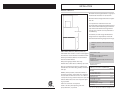
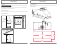
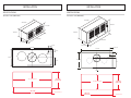
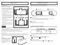
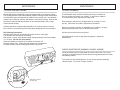
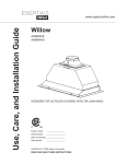
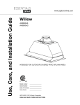
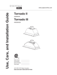
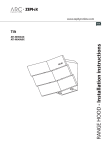
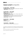
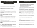
Important Safety Notice
Use, Care and Installation Guide
Read and save these instructions
Read all Instructions before Installing and operating this appliance
Important Safety Notice
MODEL: AK8000AS, AK8100S, AK8200S
READ AND SAVE THESE INSTRUCTIONS
WARNING
TO REDUCE THE RISK OF FIRE OR ELECTRIC SHOCK, DO NOT USE THIS
FAN WITH ANY SOLID-STATE CONTROL DEVICE.
WARNING
TO REDUCE THE RISK OF FIRE ELECTRIC SHOCK, OR INJURY TO
PERSONS, OBSERVE THE FOLLOWING:
a. Use this unit only in the manner intended by the manufacturer, if you have questions,
contact the manufacturer.
b. Before servicing or cleaning unit, switch power off at service panel and lock panel
to prevent power from being switched on accidentally. When the service disconnecting
means cannot be locked, securely fasten a prominent warning device, such as a tag,
to the service panel.
CAUTION
For general ventilating use only. Do not use to exhaust hazardous or explosive materials
and vapors. Take care when using cleaning agents or detergents.
Suitable for use in household cooking area.
WARNING
TO REDUCE THE RISK OF RANGE TOP GREASE FIRE:
a. Never leave surface units unattended at high settings. Boilovers cause smoking
and greasy spillovers that may ignite. Heat oils slowly on low or medium settings.
b. Always turn hood ON when cooking at high heat or when flaming food
c. Clean ventilating fans frequently. Grease should not be allowed to accumulate
on fan or filter.
d. Use proper pan size. Always use cookware appropriate for the size of the surface
element.
e. Keep fan, filters and grease laden surfaces clean.
f. Use high setting on hood only when necessary.
g. Don’t leave hood unattended when cooking.
h. Always use cookware and utensils appropriate for the type of and amount of food
being prepared.
WARNING
TO REDUCE THE RISK OF INJURY TO PERSONS IN THE EVENT OF A RANGE TOP
FIRE, OBSERVE THE FOLLOWING:
a.
SMOTHER FLAMES with a close-fitting lid, cookie sheet, or metal tray, then
turn off the burner. BE CAREFUL TO PREVENT BURNS. If the flames do not go out
immediately, EVACUATE AND CALL THE FIRE DEPARTMENT.
b.
NEVER PICK UP A FLAMING PAN – You may be burned.
c.
DO NOT USE WATER, including wet dishcloths or towels – a violent steam
explosion will result.
JAN07.0201
www.zephyronline.com
d.
Use an extinguisher ONLY if:
1. You know you have a Class ABC extinguisher, and you already know how
to operate it.
2. The fire is small and contained in the area where it started.
3. The fire department is being called.
4. You can fight the fire with your back to an exit
WARNING
TO REDUCE THE RISK OF FIRE, ELECTRIC SHOCK OR INJURY TO PERSONS,
OBSERVE THE FOLLOWING:
a. Installation work and electrical wiring must be done by qualified person (s) in
accordance with all applicable codes and standards. Including fire-rated construction.
b. Sufficient air is needed for power combustion and exhausting of gases through the
flue (chimney) of fuel burning equipment to prevent back drafting. Follow the heating
equipment manufacturer’s guideline and safety standards such as those published
by the National Fire Protection Association (NFPA) and the American Society for
Heating, Refrigeration and Air Conditioning Engineers (ASHRAE) and the local code
authorities.
c. When cuttig or drilling into wall or ceiling, do not damage electrical wiring and other
hidden utilities.
d. Ducted fans must always vent to the outdoors.
e. If this unit is to be installed over a tub or shower, it must be marked as appropriate
for the application and be connected to a GFCL (Ground Fault Interrupter protected
branch circuit).
g. NEVER place a switch where it can be reached from a tub or shower.
h. Make sure the power is off before installing, wiring or maintenancing.
WARNING
TO REDUCE THE RISK OF FIRE, USE ONLY METAL DUCTWORK.
CAUTION
To reduce risk of fire and to properly exhaust air outside - Do not vent exhaust air into
spaces within walls, ceilings, attics, crawl spaces or garages.
WARNING
TO REDUCE THE RISK OF SHOCK, THIS FAN MUST BE INSTALLED WITH AN
ISOLATING WALL CONTROL/SWITCH.
OPERATION
Always leave safety grills and filters in place. Without these components, operating
blowers could catch onto hair, fingers and loose clothing.
*NOTE: Please check www.zephyronline.com for revisions before doing any custom
work.
INSTALLATION
MOUNT HEIGHTS
Minimum mount height between range top to
hood bottom should be no less than 24".
Maximum mount height should be no higher
than 32".
Min 24"-Max 32"
It is important to install the hood at the
proper mounting height. Hoods mounted too
low could result in heat damage and fire hazard; while hoods mounted too high will be
hard to reach and will loose its performance
and efficiency.
If available, also refer range manufacturer's
height clearance requirements and recommended hood mounting height above range.
36"
Minimum clearance of 24”hood above range
height.
Maximum clearance 32" hood above range
height.
DUCTING (AK8000AS, AK8100S, AK8200S)
A minimum of 6" round or 3-1/4” x 10"rectangular
duct must be used to maintain maximum air flow
efficiency for AK8000/AK8100 and 8” minimum
must be used for AK8200.
Always use rigid type metal ducts only.
Flexible ducts could restrict air flow by up to 50%.
Also use calculation (on right) to compute total
available duct run when using elbows, transitions
and caps.
ALWAYS, when possible, reduce the number or
transitions and turns. If long duct run is required,
increase duct size from 6" to 7” or 8". If a reducer
is used, install a long reducer instead of a pancake
reducer. Reduce duct size as far away from opening as possible.
If turns or transitions are required:
Install as far away from opening and as far
apart, between 2, as possible.
Minimum Duct Size:
Round:
6" minimum for AK8000AS/AK8100S
8" minimum for AK8200S
Rectangular:
Requires an adapter. Readily available at most
hardware stores.
Duct Run Calculation:
Maximum run
AK8000
AK8100 (6" or 3-1/4” x 10") AK8200 (8”) 100 FT
Deduct:
each 90 Elbow used
each 45 elbow used
each 6" to 3/14 x 10"
transition used
each 3/14 x 10" to 6"
each 3/14 x 10" to 6"
transition used
Side Wall Cap w/ damper
Roof Cap
15 FT
9 FT
1 FT
5 FT
30 FT
30 FT
e.g.- 1 roof cap, 2x90 elbows, 1 45 elbow used:
=30' + 30' + 9' =69' used, 31' available for straight duct runs.
Page 1
INSTALLATION
INSTALLATION
DUCTING
SPECIFICATIONS
Twister (AK8000AS)
WARNING FIRE HAZARD
10-11
1-5/32”
/16”
5-15/16”
NEVER exhaust air or terminate duct work into spaces between walls, crawl spaces, ceiling,attics or
garages. All exhaust must be ducted to the outside.
1-1/16”
5”
Fasten all connections with sheet metal screws and tape all joints w/ certified Silver Tape or Duct Tape.
9-27/32”
Use Metal ductwork only.
Some Ducting Options:
11-13
/16”
26-1
9/32
”
27-9
/16”
4-3/32”
side wall cap
w/ gravity damper
side wall cap
w/ gravity damper
/16”
10-5 3/16”
11-1
1-1/4”
BACK
3-3/4”
Soffit or crawl space
Roof Pitch w/
Flashing & Cap
FRONT
C/L
cut out dimension
26-7/8”
(cut out)
Page 2
10-5/8”
(cut out)
= cut out dimension
Page 3
INSTALLATION
INSTALLATION
SPECIFICATIONS
SPECIFICATIONS
Tornado 1 unit (AK8100S)
Tornado 2 unit (AK8200S)
33-7/16"
26-19/32”
16-3/16"
11-3/16”
10-5/16”
15-9/32”
27-9/16”
34-7/16”
9-27/32”
7-7/8”
2-3/8"
2-13/16"
27-9/16”
34-7/16
1-3/8”
2”
1/2" Elec. K.O.
6"
8"
11-3/16”
5-1/8”
1/2"Elec. K.O.
16-3/16"
10”
C/L
C/L
cut out dimension
26-7/8”
(cut-out)
10-5/8”
(cut out)
= cut out dimension
Page 4
cut out dimension
33-1/2”
(cut out)
15-3/8”
(cut out)
= cutout dimension
Page 5
INSTALLATION
CONTROLS & FEATURES
INSTALLATION
CONTROLS & FEATURES (AK8100S/AK8200S)
Front View
Mounting the Range Hood
1. Determine and mark the mounting
wood frame
position of the range hood with a pencil.
2. Cut out the opening where the range
hood will be installed.
3. Cut out wall or ceiling area for clearance
of ductwork. Install ductwork prior to
range hood.
4. Determine location for the power
supply cable. After drilling access hole,
Locking clip
rout the cable into the electrical box
of the range hood. Secure with a cable
lock and connect to range hood
electrical system.
wood frame
5. Position range hood into location and
ensure spring locking clip has locked
into position.
Ductwork
wood frame
1 Speed Selection
Controls
Power supply cable
Entry into range hood
1 Speed Selection
Side View
wood frame
WARNING
This switch controls the speed of the blower. The first position is low speed,
the second is medium speed, and the third is high speed.
2 Lights On/Off
Turn lights on or off by moving this switch.
6. Fasten wood screws into wood frame
opening via the long side. Wood blocking
may be necessary if wood frame is too thin.
ELECTRICAL
2 Lights On/Off
wood
blocking
CONTROLS & FEATURES (AK8000AS)
Attach 2 screws to each
long side of AK8100/AK8200
All Electrical work must by performed by qualified electrician or person with similar technical
know how and background.
For personal safety, remove house fuse or open circuit breaker before beginning installation.
Do not use extension cord or adapter plug with this appliance.
Follow National electrical codes or prevailing local codes and ordinances.
Lights Bright / Dim / Off
III
II
I
0
II
I
0
Electrical Supply:
This appliance requires a 120V 60Hz electrical supply., and connected to an individual, properly
grounded branch circuit, protected by a 15 or 20 ampere circuit breaker or time delay fuse. Wiring
must be 2 wire w/ ground. Please also refer Electrical Diagram labeled on product.
1 Speed Selection
This switch controls the speed of the blower. I is low speed,
I I is medium speed, and I I I is high speed.
Cable Lock:
A cable locking connector (not
supplied) might also required by
local codes. Check with local
requirements and codes, purchase
and install appropriate connector if
necessary.
2 Lights Bright / Dim / Off
This switch controls the lights. Slide switch to I for dim lighting and I I for bright lighting,.
Cable Lock
Page 6
Page 7
MAINTENANCE
MAINTENANCE
CLEANING (AK8100S, AK8200S)
CLEANING (AK8000AS)
Models AK8100S and AK8200S hoods are designed with a self cleaning feature.
The centrifigal blower system automatically liquefies cooking residue accumulated
in its internal housing and deposits the residue in the residue cups. Nevertheless,
grease from cooking can also dry and adhere in the internal housing. Running the
self clean function periodically will flush out accumulated residue in the range
hood’s internal housing.
The AK8000AS metal mesh filter fitted by the factory is intended to
filter out residue and grease from cooking. It need not be replaced
on a regular basis but is required to be kept clean.
Cleaning should be completed approximately once a month under normal use.
Non corrosive, non abrasive grease cutting spray detergents are recommended.
Remove and clean by hand or in dishwasher on low setting. Or spray
degreasing detergent and leave to soak if heavily soiled.
Self Cleaning Instructions:
Remove safety grilles by unscrewing the thumb screw on each grille.
Turn blowers on lowest speed for cleaning.
With nozzle on spray, squirt grease cutting detergent directly onto blower blades
10 - 15 times. (Do not use oven cleaner)
Allow self cleaning to complete for 5 minutes, turn blower off.
Remove residue cups. Clean with mild detergent or in dishwasher.
Re-install residue cups and safety grilles before using hood.
Dry filter and re-install before using hood.
Filter should be cleaned every 30 days based on a usage of 1 hour
per day. Clean filter more often if performance decreases.
Should filter wear out due to age and prolonged use, contact the
manufacturer.
SURFACE MAINTENANCE (AK8000AS, AK8100S, AK8200S)
Clean periodically with hot soapy water and clean cotton cloth. Do not use
corrosive or abrasive detergent or steel wool/scouring pads which will scratch
and damage surface.
For heavier soil use liquid degreaser. Do not use any product containing
chlorine bleach. Do not use “orange” cleaners.
Slide off to remove
residue cups
Page 8
Page 9
MAINTENANCE
LIGHTS
Replacing Light Bulbs
CAUTION: Light bulb becomes extremely hot when turned on.
DO NOT touch bulb until switched off and cooled. Touching hot
bulbs could cause serious burns.
Make sure all power is turned off and
bulbs are not hot.
Remove by turning bulb counter
clockwise.
If bulbs are difficult to turn due to
prolonged use, firmly attach a glass
suction cup approx. the diameter of the
bulb and turn.
Replacement bulbs are available at
specialty lighting stores. Purchase type
GU-10 120V 35W halogen bulbs.
Or to order bulbs, please call our service
center: 888-880-8368or online parts store:
www.zephyronline.com
Page 10