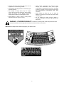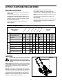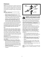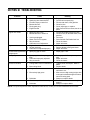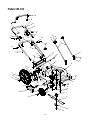
1
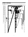
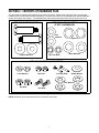
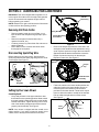
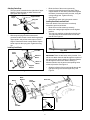
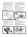
OPERATOR’S MANUAL
22” Hi-Wheel
Rotary Mowers
Model Series
500 Thur 509
IMPORTANT: Read safety rules and instructions carefully before operating equipment.
Warning: This unit is equipped with an internal combustion engine and should not be used on or near any unimproved forestcovered, brush-covered or grass-covered land unless the engine’s exhaust system is equipped with a spark arrester meeting
applicable local or state laws (if any). If a spark arrester is used, it should be maintained in effective working order by the operator.
In the State of California the above is required by law (Section 4442 of the California Public Resources Code). Other states may have
similar laws. Federal laws apply on federal lands. A spark arrester for the muffler is available through your nearest engine authorized
service dealer or contact the service department, P.O. Box 368022 Cleveland, Ohio 44136-9722.
MTD PRODUCTS INC. P.O. BOX 368022 CLEVELAND, OHIO 44136-9722
PRINTED IN U.S.A.
FORM NO. 770-10109B.fm
(10/99)
TABLE OF CONTENTS
Content
Page
Maintaining Safety ............................................................................................. 3
Slope Gauge...................................................................................................... 6
Contents of Hardware Pack ............................................................................... 7
Assembling Your Lawn Mower........................................................................... 8
Know Your Lawn Mower .................................................................................... 11
Operating Your Lawn Mower ............................................................................. 12
Making Adjustments .......................................................................................... 13
Maintaining Your Lawn Mower........................................................................... 14
Storing Your Lawn Mower.................................................................................. 16
Troubleshooting ................................................................................................. 17
Parts List............................................................................................................ 18
FINDING MODEL NUMBER
This Operator’s Manual is an important part of your new lawn mower. It will help you assemble, prepare and
maintain the unit for best performance. Please read and understand what it says.
Before you start assembling your new equipment, please locate the model plate on the
equipment and copy the information from it in the space provided below. The information on
the model plate is very important if you need help from our Customer Support Department or
an authorized dealer.
•
You can locate the model number by looking down at the rear of the deck. A sample model plate is
explained below. For future reference, please copy the model number and the serial number of the
equipment in the space below.
(Model Number)
(Serial Number)
Copy the model number here:
Copy the serial number here:
MTD PRODUCTS INC
CLEVELAND, OHIO 44136
CALLING CUSTOMER SUPPORT
If you have difficulty assembling this product or have any questions regarding the controls, operation or
maintenance of this unit, please call the Customer Support Department.
Call 1- (330) 220-4MTD (4683) or 1- (800)-800-7310 to reach a Customer Support
representative. Please have your unit’s model number and serial number ready when you
call. See previous section to locate this information. You will be asked to enter the serial
number in order to process your call .
2
SECTION 1: MAINTAINING SAFETY
This Warning symbol points out important safety instructions which, if not followed, could endanger the
personal safety and/or property of yourself and others. Read and follow all instructions in this manual
before attempting to operate your lawn mower. Failure to comply with these instructions may result in
personal injury. When you see this symbol, heed its warning.
DANGER: Your lawn mower was built to be operated according to the rules for safe operation in
this manual. As with any type of power equipment, carelessness or error on the part of the operator can
result in serious injury. This lawn mower is capable of amputating hands and feet and throwing objects.
Failure to observe the following safety instructions could result in serious injury or death.
WARNING:
The Engine Exhaust from this product contains chemicals known to the State of
California to cause cancer, birth defects or other reproductive harm.
GENERAL OPERATION
• Thoroughly inspect the area where the equipment is
to be used. Remove all stones, sticks, wire, bones,
toys and other foreign objects which could be picked
up and thrown by the mower in any direction and
cause serious personal injury to the operator or any
others allowed in the area. Plan your mowing pattern
to avoid discharge of material toward roads,
sidewalks, bystanders and the like. To help avoid a
thrown objects injury, keep children, bystanders and
helpers at least 75 feet from the mower while it is in
operation.
• Read this operator’s manual carefully in its entirety
before attempting to assemble this machine. Read,
understand, and follow all instructions on the machine
and in the manual(s) before operation. Be completely
familiar with the controls and the proper use of this
machine before operating it. Keep this manual in a
safe place for future and regular reference and for
ordering replacement parts.
• Your rotary mower is a precision piece of power
equipment, not a plaything. Therefore, exercise
extreme caution at all times. Your unit has been
designed to perform one job: to mow grass. Do not
use it for any other purpose.
• Do not put hands or feet near or under rotating parts.
Keep clear of discharge opening at all times as the
rotating blade can cause injury.
• Many injuries occur as a result of the mower being
pulled over the foot during a fall. Do not hang on to
the mower if you are falling; release the handle
immediately.
• Never allow children under 14 years old to operate a
power mower. Children 14 years old and over should
only operate mower under close parental supervision.
Only responsible individuals who are familiar with
these rules of safe operation should be allowed to
use your mower.
• Never pull the mower toward you while you are
walking. If you must back the mower away from a
wall or obstruction first look down and behind, and
then follow these steps:
• Keep the area of operation clear of all persons,
particularly small children and pets. Stop engine
when they are in the vicinity of your mower to help
prevent blade contact or thrown object injury.
Although the area of operation should be completely
cleared of foreign objects, an object may have been
overlooked and could be accidentally thrown by the
mower in any direction and cause serious personal
injury to the operator or any others allowed in the
area.
• Step back from the mower to fully extend your
arms.
• Be sure you are well balanced with sure footing.
• Pull the mower back slowly, no more than half
way toward you.
• Repeat these steps as needed.
• Do not operate the mower while under the influence
of alcohol or drugs.
• Wear sturdy, rough-soled work shoes and close-fitting
slacks and shirts. Shirts and pants that cover the
arms and legs and steel-toed shoes are
recommended. Do not wear loose fitting clothes or
jewelry. They can be caught in moving parts. Never
operate a unit in bare feet, sandals, slippery or light
weight (e.g. canvas) shoes.
• Do not engage the self-propelled mechanism on units
so equipped while starting engine.
• The blade control handle is a safety device. Never
attempt to bypass its operation. Doing so makes the
safety device inoperative and may result in personal
injury through contact with the rotating blade. The
blade control handle must operate easily in both
directions and automatically return to the disengaged
position when released.
• Always wear safety glasses or safety goggles during
operation or while performing an adjustment or repair,
to protect eyes from foreign objects that may be
thrown from the machine in any direction.
3
• Never operate the mower in wet grass. Always be
sure of your footing. A slip and fall can cause serious
personal injury. Keep a firm hold on the handle and
walk, never run. If you feel you are losing your
footing, RELEASE THE BLADE CONTROL HANDLE
IMMEDIATELY and the blade will stop rotating within
three seconds.
• Do not mow on wet grass. Reduced footing could
cause slipping.
CHILDREN
Tragic accidents can occur if the operator is not alert to the
presence of children. Children are often attracted to the
mower and the mowing activity. Never assume that children
will remain where you last saw them.
• Mow only in daylight or good artificial light.
• Stop the blade when crossing gravel drives, walks or
roads.
• Keep children out of the mowing area and under the
watchful care of a responsible adult other than the
operator.
• If the equipment should start to vibrate abnormally,
stop the engine and check immediately for the cause.
Vibration is generally a warning of trouble.
• Be alert and turn mower off if a child enters the area.
• Before and while moving backwards, look behind and
down for small children or other objects.
• Shut the engine off and wait until the blade comes to
a complete stop before removing the grass catcher or
unclogging the chute. The cutting blade continues to
rotate for a few seconds after the engine is shut off.
Never place any part of the body in the blade area
until you are sure the blade has stopped rotating.
• Never allow children under age 14 to operate the
mower. Children 14 years of age and above should
read and understand the operation instructions and
safety rules in this manual.
• Use extreme care when approaching blind corners,
shrubs, trees, or other objects that may obscure your
vision of a child or hazard.
• Never operate mower without proper guards, grass
catcher, plates or other safety protective devices in
place.
• Muffler and engine become hot and can cause a
burn. Do not touch.
SERVICE
• Only use accessories approved for this machine by
the manufacturer. Read, understand, and follow all
instructions provided with the approved accessory.
• Use extreme care in handling gasoline and other
fuels. They are extremely flammable and the vapors
are explosive.
• If situations occur which are not covered in this
manual, use care and good judgment. Contact your
dealer for assistance. Telephone 1-800-800-7310 for
the name of your nearest dealer.
• Use only an approved gasoline container.
• Never remove gas cap or add fuel while the engine is
running. Allow engine to cool at least two minutes
before refueling.
• Replace gasoline cap securely and wipe off any
spilled gasoline before starting the engine as it may
cause a fire or explosion.
SLOPE OPERATION
For your safety, use the slope gauge included as part of this
manual to measure slopes before operating this unit on a
sloped or hilly area. If the slope is greater than 15 degrees
as shown on the slope gauge, do not operate this unit on
that area or serious injury could result.
• Extinguish all cigarettes, cigars, pipes and other
sources of ignition.
• Never refuel machine indoors because flammable
vapors will accumulate in the area.
DO:
• Never store the machine or fuel container inside
where there is an open flame or spark such as a gas
water heater, space heater, or furnace.
• Mow across the face of slopes; never up and down.
Exercise extreme caution when changing direction on
slopes.
• Never run an engine inside a closed area.
• To reduce fire hazard, keep mower free of grass,
leaves, or other debris build-up. Clean up oil or fuel
spillage. Allow mower to cool at least 5 minutes
before storing.
• Watch for holes, ruts, hidden objects, or bumps. Tall
grass can hide obstacles.
• Always be sure of your footing. A slip and fall can
cause serious personal injury. If you feel you are
losing your balance release the blade control handle
immediately and the blade will stop in less than 3
seconds.
• Before cleaning, repairing, or inspecting, make
certain the blade and all moving parts have stopped.
Disconnect the spark plug wire, and keep the wire
away from the spark plug to prevent accidental
starting.
DO NOT:
• Check the blade and engine mounting bolts at
frequent intervals for proper tightness. Also, visually
inspect blade for damage (e.g., bent, cracked or
worn). Replace with blade which meets original
equipment specifications listed in this manual.
• Do not mow near drop-offs, ditches or embankments.
The operator could lose footing or balance.
• Do not mow slopes greater than 15 degrees as
shown on the slope gauge.
4
• Keep all nuts, bolts, and screws tight to be sure the
equipment is in safe working condition.
• Grass catcher components are subject to wear,
damage and deterioration, which could expose
moving parts or allow objects to be thrown. For safety
protection, frequently check components and replace
with manufacturer’s recommended parts, when
necessary.
• Never tamper with safety devices. Check their proper
operation regularly.
• After striking a foreign object, stop the engine,
remove the wire from the spark plug, and thoroughly
inspect the mower for any damage. Repair the
damage before starting and operating the mower.
• Mower blades are sharp and can cut. Wrap the
blade(s) or wear gloves, and use extra caution when
servicing them.
• Never attempt to make a wheel or cutting height
adjustment while the engine is running.
• Do not change the engine governor setting or
overspeed the engine. Excessive engine speeds are
dangerous.
WARNING - YOUR RESPONSIBILITY: Restrict the use of this power machine to persons who read,
understand and follow the warnings and instructions in this manual and on the machine.
NOTE: Not all safety labels shown may apply to your lawn mower.
5
SECTION 2: SLOPE GAUGE
Use this page as a guide to determine slopes where you may not operate safely. Do not operate your lawn mower
on such slopes.
FOL
DO
N DO
TTE
DL
IN E ,
15°
S EN
TI
NG A
15
° SL
O PE
OR A FENCE POST
A CORNER OF A BUILDING
A POWER POLE
SIGHT AND HOLD THIS LEVEL WITH A VERTICAL TREE
R EP
RE
WARNING
Do not mow on inclines with a slope in excess of 15 degrees (a rise of approximately 2-1/2 feet every 10 feet). A riding mower could
overturn and cause serious injury. If operating a walk-behind mower on such a slope, it is extremely difficult to maintain your footing
and you could slip, resulting in serious injury.
Operate RIDING mowers up and down slopes, never across the face of slopes.
Operate WALK-BEHIND mowers across the face of slopes, never up and down slopes.
6
SECTION 3: CONTENTS OF HARDWARE PACK
The lawn mower is shipped with following loose parts in the carton. Please remove all loose parts, including the
hardware pack, from the carton before discarding it. Compare the contents of the hardware pack with the hardware
shown on this page. See Figure 1. The hardware pack may contain extra items which are not used on your unit.
ATTACHING REAR WHEELS
(IF NOT ASSEMBLED)
ATTACHING FRONT WHEELS
Axle Bolts
Flat
Washers
Spacers
Wave Washers
Hex Jam Nuts
Cupped Washers
ATTACHING STRUTS (IF EQUIPPED)
Lock Washers
Hex Nuts
Carriage Bolts
Saddle Washer
Bell Washers
Hex Nuts
Hex Bolts
Figure 1
NOTE: Hardware pieces illustrated here are not drawn to actual size.
7
SECTION 4: ASSEMBLING YOUR LAWN MOWER
IMPORTANT: This unit is shipped without gasoline or oil
in the engine. Be certain to service engine with gasoline
and oil as instructed in the separate engine manual
before operating your mower.
Handle
Assembly
NOTE: Reference to right or left hand side of the mower
is observed from the operating position.
Removing Unit From Carton
•
•
•
•
Wing Nuts
Remove staples, break glue on top flaps, or cut
tape at carton end and peel along top flap to open
carton.
Remove loose parts if included with unit (i.e.,
operator’s manual, etc.)
Cut along corners, lay carton down flat, and remove
packing material.
Roll or slide unit out of carton and check carton
thoroughly for loose parts.
Handle Bracket
Assemblies
Figure 3
•
Disconnecting Spark Plug Wire
Before setting up your lawn mower, disconnect the
spark plug wire from the spark plug and ground to a bolt
on the engine. See Figure 2.
Remove the hairpin clips from the outer hole in the
weld pins on the handle bracket assemblies. Using
a pair of pliers, squeeze one leg of the lower handle
against the handle bracket assemblies. Insert the
hairpin clip into the inner hole on the weld pin.
Repeat on other side. See Figure 4.
Lower
Handle
Hairpin
Clip
Bolt
Spark Plug
Wire
Handle Bracket
Assembly
Spark
Plug Wire
Figure 4
Spark Plug
•
Figure 2
Setting Up Your Lawn Mower
Assembling Handle
•
Lift up and pull back on the upper handle to raise
the handle into the operating position. Make certain
the lower handle is seated securely into the handle
bracket assemblies. Tighten the wing nuts on each
side of the handle (carriage bolts must be seated
properly into the handle). See Figure 3.
Fasten the cables to the lower handle with the two
cable ties found on the lower handle. Be sure to
insert the post on the cable ties into the holes
provided on the lower handle. These holes may be
found on either the inside or outside of the handles.
Pull the cable ties tight and trim off the excess.
See Figure 5.
Cable Tie
Lower
Handle
NOTE: Your mower is shipped with the handle in the
higher position. If you wish to lower the height of the
handle, refer to the Adjustment Section at this time.
Figure 5
8
Attaching Starter Rope
•
•
•
The rope guide is attached to the right side of upper
handle. Loosen the wing nut which secures the
rope guide. See Figure 6.
Upper Handle
Starter
Rope
•
Wing Nut
Block the front of the mower up securely.
Insert front axle bolt through front wheel. Place
cupped washer on axle bolt (crowned side against
the wheel). Insert axle bolt into pivot bar, using the
corresponding hole. Tighten securely.
See Figure 7.
Assemble the other side in the same manner.
Installing Rear Wheels and Axle Shaft
If the rear wheels of the mower are not already
assembled, proceed as follows.
Rope
Guide
Lower
Handle
•
•
•
Figure 6
•
With the spark plug wire disconnected and
grounded, hold the blade control handle against the
upper handle, and pull the starter rope out of the
engine. Release the blade control handle. Slip the
starter rope into the rope guide. Tighten the wing
nut.
Block the rear of the mower up securely.
Move rear cutting height adjusters to the highest
position.
The rear axle shaft has a right side and a left side.
The right side has two tabs and the left side has
one tab. See Figure 8.
Right
Left
Installing Front Wheels
Axle Shaft
Pivot Bar
Front
Wheel
Figure 8
Attach 8”
Wheel
Axle
Bolt
IMPORTANT:There are two holes on the pivot bar. You
will have to attach the axle shaft through the top hole of
the right pivot bar when installing 16” diameter wheels,
and through the bottom hole when installing 14”
diameter wheels. Use the same corresponding holes
on the left pivot bar. See Figure 9.
Attach 7”
Wheel
Cupped
Washer
•
Figure 7
Slide the left side of the rear axle shaft through the
right pivot bar (pivot bar with keyed hole). See
Figure 9.
Left Pivot Bar
Wheel
Wave
Washer
Flat
Washer
Right
Pivot Bar
Rear Axle
Spacer
For 16”
Wheel
Hex
Jam Nut
For 14”
Wheel
Figure 9
9
•
•
•
•
Rotate the axle shaft until first tab on the right side
of the axle shaft clears the hole in the right pivot
bar. Rotate further until second tab on the right side
of the axle shaft locks into the hole in the same
pivot bar. The tab on the left side of the axle shaft
should hit on the surface of the left pivot bar.
Place one spacer on the rear axle, then one wave
washer.
Place wheel assembly on end of axle. Secure with
one flat washer and one hex jam nut. Tighten
securely.
Repeat above steps to assemble the other wheel
and then place all four height adjusters in the same
relative position.
•
•
•
Removing Chute Retainer
The chute deflector on your mower is held in an upright
position by a retainer for shipping purposes only.
Remove the retainer, following steps below, before
running the mower for the first time.
•
Attaching Struts (If Equipped)
Carriage
Bolt
Lock
Washer
Place one flat washer over carriage bolt.
Insert carriage bolt up through hole in deck beside
the engine and through the strut. Secure with lock
washer and hex nut from the hardware pack.
Repeat step on the other side. See Figure 11.
Tighten all nuts and bolts on both ends of the strut
securely.
•
Push the chute deflector up and towards the
engine. Holding the deflector in this position,
remove the retainer. See Figure 12.
Lower the chute deflector carefully to its operating
position keeping your fingers out of the way.
Saddle
Washer
Strut
Raise Chute
Deflector
Hex Nut
Hex
Nut
Remove
Retainer
Figure 12
Bell
Washer
WARNING: The chute retainer must be
removed and discarded before operating
the mower.
Hex Screw
Figure 10
Installing Mulching Baffle
•
Once the upper handle is secured, removed the
wing nut from one side of the of the handle and
discard. See Figure 10.
• Holding the carriage bolt that is already placed on
the handle, place saddle washer, and then strut
over the carriage bolt.
• Place the lock washer and the hex nut over the bolt
threading only a few turns, just enough to hold the
handle.
• Repeat on other side.
Attach the other end of struts as follows:
If your mower is equipped with the optional mulching
baffle, install it following instructions below.
•
•
•
Insert the mulching baffle so that the notches at the
bottom of the baffle sit firmly on the lip of the deck
opening. See Figure 13.
Slide the hooks of the baffle over the hinge pin on
the discharge chute. Make sure that the hooks
snaps into place, locking the mulching baffle firmly
on to the mower.
Release the chute deflector.
Attach End of
Struts Here
Hinge Pin
Chute
Deflector
Baffle
Hook
Figure 11
Insert Notches
on Top of Lip
Figure 13
10
Baffle
Hook
SECTION 5: KNOW YOUR LAWN MOWER
Read this owner’s manual and safety rules before operating your lawn mower. Compare the illustrations in Figure
14 with your lawn mower to familiarize yourself with the location of various controls and adjustments. Save this
manual for future reference.
WARNING: The operation of any lawn mower can result in foreign objects being thrown into the
operator’s eyes and causing severe eye damage. Always wear safety glasses while operating the
mower, or while performing any adjustments or repairs on it.
Blade Control
Handle
Recoil
Starter
Cutting Height
Adjustment Lever
Discharge
Chute
Figure 14
Recoil Starter
Engine Controls
The recoil starter is attached to the right lower handle.
Stand behind the unit and pull the recoil starter to start
the unit. See Figure 14.
See the separate engine manual for the location and
function of the controls on the engine.
Blade Control Handle
Stopping Engine
The blade control handle is located on the upper handle
of the mower. The blade control handle must be
depressed in order to operate the unit. Release blade
control handle to stop engine and blade.
•
•
WARNING: This blade control mechanism
is a safety device. Never attempt to bypass
its operations.
Release blade control handle to stop the engine
and the blade.
Disconnect spark plug wire and ground it to a bolt
on the engine.
WARNING: Before using your lawn mower,
again refer to the Safety Section in this
manual. Always be careful.
Cutting Height Adjustment Lever
These levers are located on each front wheel and are
used to adjust the cutting height. Both levers have to be
at the same relative position to ensure uniform cut.
11
SECTION 6: OPERATING YOUR LAWN MOWER
Towards Better Mower Performance
1. Read this manual in its entirety before you start
the lawn mower. Instructions given here have
been designed for maintaining safety while
getting the best performance from your mower.
Follow the instructions closely.
2. Pour fresh, clean gasoline into the mower’s gas
tank until the tank is full. Do not use gasoline
that is more than 30 days old.
3. Always use a fuel stabilizer. It will double the life
of the gasoline used.
4. Make sure to connect the mower’s spark plug
wire before trying to start the engine.
5. Add engine oil to the oil fill on the mower engine.
Check the dipstick and add more if necessary.
Remember that the oil level has to touch the fill
line.
6. Locate the primer decal near the primer bulb on
the engine, and read its instruction. Using your
thumb, press the primer bulb slowly as many
times as the decal advises.
7. Hold control handle down and pull rope firmly to
start the engine.
8. Set cutting height adjustment lever to middle
setting and mow a single pass on your lawn;
then adjust to desired height for a closer cut.
9. When bagging the grass clippings, remove
mulch plug/cover and store.
10. To mulch insert the mulch plug/cover on the
mower.
11. In heavy growing season, it may be necessary
to mow lawn twice weekly. Clumps of grass
clippings left behind on the lawn usually means
that the grass is too high to mulch.
12. Before storing the lawn mower for the winter,
use stabilizer-treated fuel and run the tank dry.
13. Thirty days before start of the new season,
check the air filter, spark plug and blade on the
lawn mower, and replace if needed.
For more details about proper lawn care, visit our website at www.mtdproducts.com/machines/tips
WARNING: Keep hands and feet away from
chute area on the cutting deck. The
operation of any lawn mower can result in
foreign objects being thrown into the eyes,
which can result in severe eye damage.
Always wear safety glasses or eye shields.
•
•
•
NOTE: For shipping purposes your mower is set with
the wheels in a low cutting height position. For best
results raise the cutting position until it is determine
which height is best for your lawn. See the Adjustment
Section for details.
•
Gas and Oil Fill-Up
Service the engine with gasoline and oil as instructed in
the separate engine manual packed with your mower.
Read instructions carefully.
Using Your Lawn Mower
Be sure that the lawn is clear of stones, sticks, wire, or
other objects which could damage the lawn mower or
the engine. Such objects could be accidently thrown by
the mower in any direction and cause serious personal
injury to the operator and others.
WARNING: Never fill fuel tank indoors with
engine running or until the engine has
been allowed to cool for at least two
minutes after running.
For best results, do not cut wet grass because it tends
to stick to the underside of the mower, preventing
proper discharge of grass clippings, and could cause
you to slip and fall. New grass, thick grass, or wet grass
may require a narrower cut.
Starting Engine
•
Prime engine as instructed in the separate engine
manual packed with your unit.
Your lawn mower may be equipped with a constant
speed throttle, which is set at full throttle for best
performance.
Stand behind the mower and squeeze the blade
control handle against the upper handle.
Grasp recoil starter handle and pull rope out slowly
until engine reaches the start of compression cycle
(rope will pull slightly harder at this point). Let the
rope rewind slowly. Pull rope with a rapid,
continuous, full arm stroke. Keeping a firm grip on
the starter handle, let the rope return to the starter
slowly.
Attach spark plug wire to spark plug. Make certain
the metal cap on the end of the spark plug is
fastened securely over the metal tip on the spark
plug.
12
Mulching
For a healthier lawn, never cut off more than one-third
of the total length of the grass. Your lawn should be cut
in the fall as long as there is growth. This mower is
designed to be operated at full throttle to give you the
best cut and do the most effective job of mowing or
mulching.
For effective mulching, do not cut wet grass because it
tends to stick to the underside of the deck, preventing
proper mulching of grass clippings. New or thick grass
may require a narrower cut. The ground speed should
be adjusted to the condition of the lawn. If mowing has
been delayed and the grass has been allowed to grow
in excess of 4”, mulching is not recommended. Mow
using the side discharge to reduce the grass height to 3
1/4” maximum before mulching.
WARNING: If you strike a foreign object,
stop the engine. Remove wire from the
spark plug, thoroughly inspect the mower
for any damage, and repair the damage
before restarting and operating the
mower. Extensive vibration of the mower
during operation is an indication of
damage. The unit should be promptly
inspected and repaired.
SECTION 7: MAKING ADJUSTMENTS
WARNING: Do not at any time make any
adjustments without first stopping engine
and disconnecting spark plug wire.
•
•
Cutting Height Adjustment
•
Height Adjustment
Lever
•
•
•
Remove the starter rope from the rope guide.
Remove the upper handle by removing the hand
knobs and carriage bolts. Lay the upper handle out
of the way, being careful not to bend or kink the
cables.
Remove the hairpin clips from the weld pins on the
handle brackets. Press out on the legs of the lower
handle. Remove lower handle from the mower.
Turn lower handle around so the notch on the
bottom of the lower handle is facing forward.
Reassemble, placing the bottom holes in the
handle over the weld pins in the handle mounting
bracket. See Figure 16.
Reassemble the upper handle to the lower handle.
Place the hairpin clips in the inner holes in the weld
pins and attach the starter rope as instructed in the
Assembly Section.
Figure 15
An adjusting plate and spring lever at each wheel
position provides cutting height adjustment. Each
adjusting plate has nine height positions. When the
spring lever is moved from one location to another the
height of cut will be changed. Simply depress the lever
towards wheel and move lever assembly to desired
position. See Figure 15.
Notch
Lower Handle
Figure 16
IMPORTANT: All wheels must be placed in the same
Engine Adjustments
relative position. For rough or uneven lawns, move the
height adjustment lever to a higher position. This will
help stop scalping of the grass.
See the separate engine manual packed with your unit
for adjustments to the engine.
Handle Height Adjustment
Your mower is shipped with the handle in the higher
height position. To lower the height proceed as follows:
13
SECTION 8: MAINTAINING YOUR LAWN MOWER
General Recommendations
•
•
•
•
Always observe safety rules when performing any
maintenance.
The warranty on this lawn mower does not cover
items that have been subjected to operator abuse
or negligence. To receive full value from the
warranty, operator must maintain the lawn mower
as instructed in this manual.
Changing of engine governed speed will void
engine warranty.
Some adjustments will have to be made
periodically to maintain your unit properly. All
adjustments in the Making Adjustments section of
this manual should be checked at least once each
season.
Periodically check all fasteners and make sure
these are tight.
Follow the maintenance schedule under Customer
Responsibilities to get quality performance from
your lawn mower.
•
•
ho
ur
s
ou
rs
Ev
er
y
50
25
h
Ev
er
y
SERVICE
Ev
er
y
e
us
ea
ch
SCHEDULE
Af
ter
MAINTENANCE
10
0h
ou
rs
On
ce
as
ea
so
Be
n
for
es
tor
ag
e
Customer Responsibilities
DATES
PRODUCT
Lubricate wheels
Lubricate blade control
Clean deck
Blade care
ENGINE
Change oil
Replace air filter
Clean engine
Check spark plug
Check spark arrester (if any)
Lubrication
Always stop engine and disconnect spark
plug wire before cleaning, lubricating or
doing any kind of service work on the lawn
mower.
Lubricate
Blade Control: Lubricate the pivot points on the blade
control handle at least once a season with light oil. The
blade control must operate freely in both directions.
See Figure 17.
Wheels: Lubricate the wheels at least once a season
with light oil (or motor oil). If the wheels are removed for
any reason, lubricate the surface of the axle bolt and
inner surface of the wheel with light oil. See Figure 17.
Engine: Follow the separate engine manual packed
with you unit for lubrication instructions.
Figure 17
14
Maintenance
Blade
Adapter
NOTE: When tipping the unit, empty the fuel tank and
keep the spark plug side of engine up. Never tip the
mower more than 90 degrees and do not leave the
mower tipped for any length of time. Oil can drain into
the upper part of the engine causing a starting problem.
Blade Bell
Support
Engine
Refer to the separate engine manual for all engine
maintenance instructions.
Hex Bolt
•
Maintain engine oil as instructed in the separate
engine manual packed with your unit.
• Service air cleaner every 25 hours under normal
conditions. Poor engine performance and flooding
usually indicate that the air cleaner should be
serviced. To service the air cleaner, refer to the
separate engine manual packed with your unit.
• The spark plug should be cleaned and the gap
reset once a season. Spark plug replacement is
recommended at the start of each mowing season.
Clean the engine regularly with a cloth or brush. Keep
the cooling system (blower housing area) clean to
permit proper air circulation which is essential to engine
performance and life. Be certain to remove all grass,
dirt, and combustible debris from muffler area.
Figure 18
WARNING: Periodically inspect the blade
adapter for cracks, especially if you strike
a foreign object. Replace when necessary.
When sharpening the blade, follow the original angle of
grind as a guide. It is extremely important that each
cutting edge receives an equal amount of grinding to
prevent an unbalanced blade. An unbalanced blade will
cause excessive vibration when rotating at high
speeds. It may cause damage to the mower, and could
break causing personal injury.
The blade can be tested by balancing it on a round
shaft screwdriver. Remove metal from the heavy side
until it balances evenly. It is recommended that the
blade always be removed from the adapter when
testing for balance. Before reinstalling the blade and
the blade adapter to the unit, lubricate the engine
crankshaft and the inner surface of the blade adapter
with light oil.
Deck
The underside of the mower deck should be cleaned
after each use to prevent a buildup of grass clippings,
leaves, dirt, or other matter. If this debris is allowed to
accumulate, it will invite rust and corrosion, and may
prevent proper mulching, discharge, or bagging. The
deck may be cleaned by tilting the mower and scraping
clean with a suitable tool (make certain the spark plug
wire is disconnected).
•
IMPORTANT: We do not recommend the use of a
pressure washer or garden hose to clean your unit. The
use of water will result in shorten life and reduce
serviceability.
•
•
Cutting Blade Removal, Replacement, and Sharpening
•
•
•
•
When removing the cutting blade for sharpening or
replacement, protect your hands with a pair of
heavy gloves or use a heavy rag to hold the blade.
Remove the bolt and the blade bell support which
hold the blade and the blade adapter to the engine
crankshaft. See Figure 18.
Remove the blade and the adapter from the
crankshaft.
•
Be sure to install the blade with the side of the
blade marked “Bottom” (or with part number) facing
the ground when the mower is in the operating
position.
Slide the blade adapter onto the engine crankshaft.
Place the blade on the adapter. Be certain the
blade is aligned and seated on the blade adapter
flanges.
Place blade bell support on blade. Make sure the
notches on the blade bell support are aligned with
small holes in the blade.
Replace hex bolt and tighten hex bolt to torque: 450
in. lbs. min., 600 in. lbs. max.
NOTE: To ensure safe operation of your mower, the
blade bolt must be checked periodically for correct
torque.
15
SECTION 9: STORING YOUR LAWN MOWER
The following steps should be taken to prepare your
lawn mower for storage.
•
Clean and lubricate mower thoroughly as described
in the lubrication instructions.
IMPORTANT:We do not recommend the use of a
pressure washer or garden hose to clean your unit. The
use of water will result in shorten life and reduce
serviceability.
•
•
•
Refer to engine manual for correct engine storage
instructions.
Coat mower’s cutting blade with chassis grease to
prevent rusting.
Store mower in a dry, clean area. Do not store next
to corrosive materials, such as fertilizer.
NOTE: When storing any type of power equipment in a
poorly ventilated or metal storage shed, care should be
taken to rust-proof the equipment. Using a light oil or
silicone, coat the equipment, especially cables and all
moving parts.
16
SECTION 10: TROUBLESHOOTING
Problem
Cause
Remedy
Engine fails to start
1.
2.
3.
4.
5.
6.
Engine runs erratic
1. Spark plug wire loose.
2. Blocked fuel line or stale fuel.
3.
4.
5.
6.
Engine overheats
Blade control handle disengaged.
Spark plug wire disconnected.
Fuel tank empty or stale fuel.
Blocked fuel line.
Faulty spark plug.
Engine flooded
Vent in gas plugged.
Water or dirt in fuel system.
Dirty air cleaner.
Carburetor out of adjustment.
1. Engine oil level low.
2. Air flow restricted.
3. Carburetor not adjusted properly.
1.
2.
3.
4.
5.
6.
Engage blade control handle.
Connect wire to spark plug.
Fill tank with clean, fresh gasoline.
Clean fuel line.
Clean, adjust gap, or replace.
Wait a few minutes to restart, but do not
prime.
1. Connect and tighten spark plug wire.
2. Clean fuel line; fill tank with clean, fresh
gasoline
3. Clear vent.
4. Drain fuel tank. Refill with fresh fuel.
5. Clean air cleaner.
6. Adjust carburetor.
1. Fill crankcase with proper oil.
2. Remove blower housing and clean.
3. Adjust carburetor.
Occasional skip (hesitates) 1. Spark plug gap too close.
at high speed
1. Adjust gap to .030”.
Idles poorly
1. Spark plug fouled, faulty or gap too
wide.
2. Carburetor improperly adjusted.
3. Dirty air cleaner.
1. Reset gap to .030” or replace spark
plug.
2. Adjust carburetor.
3. Clean air cleaner.
Excessive vibration
1. Cutting blade loose or unbalanced.
1. Tighten blade and adapter. Balance
blade.
2. Replace blade.
2. Bent cutting blade.
Mower will not mulch grass 1. Wet grass.
2. Excessively high grass.
3. Dull blade.
Uneven cut
1. Wheels not positioned correctly.
2. Dull blade.
1. Do not mow when grass is wet; wait
until later to cut.
2. Mow once at a high cutting height, then
mow again at desired height or make a
narrower cutting path.
3. Sharpen or replace blade.
1. Place all four wheels in same height
position.
2. Sharpen or replace blade.
NOTE: For repairs beyond the minor adjustments listed above, contact your nearest authorized service dealer.
17
Models 500-509
1
56
33
15
14
29
37
64 62
12
38
63
36
61
35
36
26
8
25
34
60
52
24
59
58
17
27
39
54
30
53
2
31
55
18
32
40
50
48
47
19
45
41
5
49
51 46
40
18
44
43
28
42
57
3
20
39
22
4
6
23
21
18
Models 500-509
Ref.
No.
1.
2.
3.
4.
5.
6.
8.
14.
15.
17.
18.
19.
20.
21.
22.
23.
24.
25.
26.
27.
28.
29.
30.
31.
32.
Part No.
747-0824
647-0004
747-0615
734-1864
734-1842
734-1987
734-1841
734-1781
738-0102
712-0328
742-0642
742-0742
749-0928
746-0883
710-1270
710-0793
712-0798
682-0518
682-0517
736-0105
710-1044
748-0376C
736-0524A
17098
731-1026
746-0551
746-0737
682-0084
710-0654A
720-0279
736-0504
782-0519A
782-0520A
712-3020
Part Description
Ref.
No.
Standard Control Handle
Deluxe Control Handle (Shown)
Control Handle
Rear Wheel Bar Grey
Rear Wheel Aero Grey
Front Wheel Bar Grey
Front Wheel w/ Plastic Bearing
Front Wheel w/o Bearing
Front Axle Bolt
Hex Nut 3/8-24
Standard Blade 22”
Mulching Blade 22”
Lower Handle
Control Cable Housing
Hex Screw 1/4-20 x 1.3
Ribbed Neck Bolt 3/8-24 x .80
Hex Nut 3/8-16
Handle Bracket Ass’y - RH
Handle Bracket Ass’y - LH
Bell Washer
Hex Bolt 3/8-24 x 1.5”
Blade Adapter
Blade Bell Support
Hinge Clip
Rear Flap Ass’y
Control Cable - B&S 43”
Control Cable - Tec 51”
Deck Assembly 22”
Hex Washer Screw
Handle Knob 1/4-20
Wave Washer
Pivot Bar - LH
Pivot Bar - RH
Hex Jam Nut 3/8-16
33.
34.
35.
36.
37.
38.
39.
40.
41.
42.
43.
44.
45.
46.
47.
48.
49.
50.
51.
52.
53.
54.
55.
56.
57.
58.
59.
60.
61.
62.
63.
64.
† If Equipped
19
Part No.
749-0705
714-0104
726-0240
710-1174
710-1205
720-0276
738-0507B
732-0404
720-0190
15262B
15261A
736-0356
14578
14579
736-0270
710-0599
747-0710
17032
732-0593
731-1034
738-0878
736-0331
750-0151
736-3050
720-0295
731-1386A
710-0751
736-0270
712-0287
749-0939
712-0267
736-0451
736-0119
Part Description
Upper Handle
Internal Cotter Pin
Cable Tie
Curved Bolt 5/16-18 x 2”
Rope Guide
Hand Knob
Shoulder Bolt
Spring Lever Assembly
Knob
Pivot Bar
Height Adjuster Plate
Bell Washer
Front Height Adj Assembly - RH
Front Height Adj Assembly - LH
Bell Washer
Hex Tap Screw 1/4-20 x .5”
Hinge Pin
Adapter Plate
Torsion Spring
Chute Deflector Ass’y
Rear Axle
Bell Washer
Spacer
Flat Washer
Foam Grip †
Mulching Baffle †
Hex Bolt 1/4-20 x .620 †
Bell Washer †
Hex Nut 1/4-20 †
Strut †
Hex Nut 5/16-18 †
Saddle Washer †
Lock Washer †
MANUFACTURER’S LIMITED WARRANTY FOR:
The limited warranty set forth below is given by MTD PRODUCTS INC (“MTD”) with respect to new merchandise purchased and used in the United States, its possessions and
territories.
MTD warrants this product against defects in material and
workmanship for a period of two (2) years commencing on
the date of original purchase and will, at its option, repair or
replace, free of charge, any part found to be defective in
material or workmanship. This limited warranty shall only
apply if this product has been operated and maintained in
accordance with the Operator’s Manual furnished with the
product, and has not been subject to misuse, abuse, commercial use, neglect, accident, improper maintenance, alteration, vandalism, theft, fire, water or damage because of
other peril or natural disaster. Damage resulting from the
installation or use of any accessory or attachment not
approved by MTD Products Inc. for use with the product(s)
covered by this manual will void your warranty as to any
resulting damages.
Normal wear parts or components thereof are subject to separate terms as follows: All normal wear part or component
failures will be covered on the product for a period of 90 days
regardless of cause. After 90 days, but within the two year
period, normal wear part failures will be covered ONLY IF
caused by defects in material or workmanship of OTHER
component parts. Normal wear parts and components
include, but are not limited to, belts, blades, blade adapters,
grass bags, rider deck wheels, seats, snow thrower skid
shoes, shave plates and tires. Batteries are covered by a 90day limited replacement warranty.
HOW TO OBTAIN SERVICE: Warranty service is available,
WITH PROOF OF PURCHASE THROUGH YOUR LOCAL
AUTHORIZED SERVICE DEALER. To locate the dealer in
your area, please check for a listing in the Yellow Pages or
contact the Customer Service Department of MTD PRODUCTS INC by calling 1-800-800-7310 or writing to P.O. Box
368022, Cleveland, Ohio 44136-9722.
This limited warranty does not provide coverage in the
following cases:
a. The engine or component parts thereof. These items
carry a separate manufacturer’s warranty. Please refer to
the applicable manufacturer’s warranty on these items.
b. Log splitter pumps, valves and cylinders have a separate
one year warranty.
c. Routine maintenance items such as lubricants, filters,
blade sharpening and tune-ups, or adjustments such as
brake adjustments, clutch adjustments or deck adjustments; and normal deterioration of the exterior finish due
to use or exposure.
d. MTD does not extend any warranty for products sold or
exported outside of the United States of America, its
possessions and territories, except those sold through
MTD’s authorized channels of export distribution.
No implied warranty, including any implied warranty of
merchantability or fitness for a particular purpose,
applies after the applicable period of express written
warranty above as to the parts as identified. No other
express warranty or guaranty, whether written or oral,
except as mentioned above, given by any person or
entity, including a dealer or retailer, with respect to any
product shall bind MTD. During the period of the Warranty, the exclusive remedy is repair or replacement of
the product as set forth above. (Some states do not allow
limitations on how long an implied warranty lasts, so the
above limitation may not apply to you.)
The provisions as set forth in this Warranty provide the
sole and exclusive remedy arising from the sales. MTD
shall not be liable for incidental or consequential loss or
damages including, without limitation, expenses
incurred for substitute or replacement lawn care services, for transportation or for related expenses, or for
rental expenses to temporarily replace a warranted product. (Some states do not allow the exclusion or limitation of
incidental or consequential damages, so the above exclusion
or limitation may not apply to you.)
In no event shall recovery of any kind be greater than the
amount of the purchase price of the product sold. Alteration
of the safety features of the product shall void this Warranty.
You assume the risk and liability for loss, damage, or injury to
you and your property and/or to others and their property
arising out of the use or misuse or inability to use the product.
This limited warranty shall not extend to anyone other than
the original purchaser, original lessee or the person for whom
it was purchased as a gift.
How State Law Relates to this Warranty: This limited warranty gives you specific legal rights, and you may also have
other rights which vary from state to state.