1
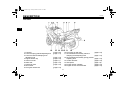
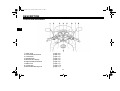
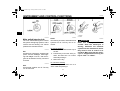
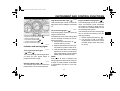
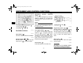
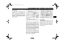
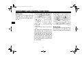
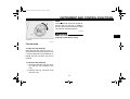
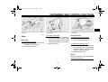
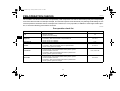
OWNER’S MANUAL
FJR1300N
YAMAHA MOTOR CO., LTD.
PRINTED ON RECYCLED PAPER
PRINTED IN JAPAN
2001 · 3 - 0.3 × 1 CR
(E)
5JW-28199-20
H_5KS_Toc0.fm Page 2 Monday, August 21, 2000 11:11 AM
E_5jw.book Page 1 Friday, March 30, 2001 2:14 PM
EAU00000
INTRODUCTION
1-
Congratulations on your purchase of the Yamaha FJR1300. This model is the result
of Yamaha’s vast experience in the production of fine sporting, touring, and pacesetting racing machines. It represents the high degree of craftsmanship and reliability
that have made Yamaha a leader in these fields.
This manual will give you an understanding of the operation, inspection, and basic
maintenance of this motorcycle. If you have any questions concerning the operation
or maintenance of your motorcycle, please consult a Yamaha dealer.
E_5jw.book Page 1 Friday, March 30, 2001 2:14 PM
IMPORTANT MANUAL INFORMATION
Particularly important information is distinguished in this manual by the following notations:
The Safety Alert Symbol means ATTENTION! BECOME ALERT! YOUR SAFETY IS
INVOLVED!
Failure to follow WARNING instructions could result in severe injury or death to the
motorcycle operator, a bystander, or a person inspecting or repairing the
motorcycle.
WARNING
CAUTION:
A CAUTION indicates special precautions that must be taken to avoid damage to the
motorcycle.
NOTE:
A NOTE provides key information to make procedures easier or clearer.
NOTE:
● This manual should be considered a permanent part of this motorcycle and should remain
with it even if the motorcycle is subsequently sold.
● Yamaha continually seeks advancements in product design and quality. Therefore, while
this manual contains the most current product information available at the time of printing,
there may be minor discrepancies between your motorcycle and this manual. If you have
any questions concerning this manual, please consult your Yamaha dealer.
_
_
EAU00005
E_5jw.book Page 2 Friday, March 30, 2001 2:14 PM
IMPORTANT MANUAL INFORMATION
EW000002
WARNING
PLEASE READ THIS MANUAL CAREFULLY AND COMPLETELY BEFORE OPERATING
THIS MOTORCYCLE.
_
_
E_5jw.book Page 3 Friday, March 30, 2001 2:14 PM
IMPORTANT MANUAL INFORMATION
EAU03337
FJR1300N
OWNER’S MANUAL
© 2001 by Yamaha Motor Co., Ltd.
1st Edition, March 2001
All rights reserved.
Any reprinting or unauthorized use
without the written permission of
Yamaha Motor Co., Ltd.
is expressly prohibited.
Printed in Japan.
E_5jw.book Page 1 Friday, March 30, 2001 2:14 PM
TABLE OF CONTENTS
EAU00009
1 SAFETY INFORMATION
1
2 DESCRIPTION
2
3 INSTRUMENT AND CONTROL FUNCTIONS
3
4 PRE-OPERATION CHECKS
4
5 OPERATION AND IMPORTANT RIDING POINTS
5
6 PERIODIC MAINTENANCE AND MINOR REPAIR
6
7 MOTORCYCLE CARE AND STORAGE
7
8 SPECIFICATIONS
8
9 CONSUMER INFORMATION
9
INDEX
E_5jw.book Page 2 Friday, March 30, 2001 2:14 PM
E_5jw.book Page 1 Friday, March 30, 2001 2:14 PM
SAFETY INFORMATION
Safe riding .......................................................................................... 1-1
Protective apparel .............................................................................. 1-3
Modifications ...................................................................................... 1-3
Loading and accessories ................................................................... 1-3
Gasoline and exhaust gas.................................................................. 1-5
Location of important labels .............................................................. 1-7
1
E_5jw.book Page 1 Friday, March 30, 2001 2:14 PM
SAFETY INFORMATION
EAU00014*
1-
1
MOTORCYCLES ARE SINGLE TRACK VEHICLES. THEIR SAFE USE AND OPERATION ARE DEPENDENT UPON THE USE OF PROPER RIDING TECHNIQUES AS WELL AS THE EXPERTISE OF
THE OPERATOR. EVERY OPERATOR SHOULD KNOW THE FOLLOWING REQUIREMENTS BEFORE RIDING THIS MOTORCYCLE.
HE OR SHE SHOULD:
1. OBTAIN THOROUGH INSTRUCTIONS FROM A COMPETENT SOURCE ON ALL ASPECTS OF
MOTORCYCLE OPERATION.
2. OBSERVE THE WARNINGS AND MAINTENANCE REQUIREMENTS IN THE OWNER’S MANUAL.
3. OBTAIN QUALIFIED TRAINING IN SAFE AND PROPER RIDING TECHNIQUES.
4. OBTAIN PROFESSIONAL TECHNICAL SERVICE AS INDICATED BY THE OWNER’S MANUAL
AND/OR WHEN MADE NECESSARY BY MECHANICAL CONDITIONS.
Safe riding
1. Always make pre-operation checks. Careful checks may help prevent an accident.
2. This motorcycle is designed to carry the operator and a passenger.
3. The failure of motorists to detect and recognize motorcycles in traffic is the predominating cause of
automobile/motorcycle accidents. Many accidents have been caused by an automobile driver who
did not see the motorcycle. Making yourself conspicuous appears to be very effective in reducing the
chance of this type of accident.
Therefore:
a. Wear a brightly colored jacket.
b. Use extra caution when you are approaching and passing through intersections, since intersections are the most likely places for motorcycle accidents to occur.
c. Ride where other motorists can see you. Avoid riding in another motorist’s blind spot.
1-1
E_5jw.book Page 2 Friday, March 30, 2001 2:14 PM
SAFETY INFORMATION
4. Many accidents involve inexperienced operators. In fact, many operators who have been involved in
accidents do not even have a current motorcycle license.
a. Make sure that you are qualified and that you only lend your motorcycle to other qualified operators.
b. Know your skills and limits. Staying within your limits may help you to avoid an accident.
c. We recommend that you practice riding your motorcycle where there is no traffic until you have
become thoroughly familiar with the motorcycle and all of its controls.
5. Many accidents have been caused by error of the motorcycle operator. A typical error made by the
operator is veering wide on a turn due to EXCESSIVE SPEED or undercornering (insufficient lean
angle for the speed).
a. Always obey the speed limit and never travel faster than warranted by road and traffic conditions.
b. Always signal before turning or changing lanes. Make sure that other motorists can see you.
6. The posture of the operator and passenger is important for proper control.
a. The operator should keep both hands on the handlebar and both feet on the operator footrests
during operation to maintain control of the motorcycle.
b. The passenger should always hold onto the operator, the seat strap or grab bar, if equipped, with
both hands and keep both feet on the passenger footrests.
c. Never carry a passenger unless he or she can firmly place both feet on the passenger footrests.
7. Never ride under the influence of alcohol or other drugs.
8. This motorcycle is designed for on-road use only. It is not suitable for off-road use.
1-2
1
E_5jw.book Page 3 Friday, March 30, 2001 2:14 PM
SAFETY INFORMATION
Protective apparel
1
The majority of fatalities from motorcycle accidents are the result of head injuries. The use of a safety
helmet is the single most critical factor in the prevention or reduction of head injuries.
1. Always wear an approved helmet.
2. Wear a face shield or goggles. Wind in your unprotected eyes could contribute to an impairment of vision that could delay seeing a hazard.
3. The use of a jacket, heavy boots, trousers, gloves, etc., is effective in preventing or reducing abrasions or lacerations.
4. Never wear loose-fitting clothes, otherwise they could catch on the control levers, footrests, or wheels
and cause injury or an accident.
5. Never touch the engine or exhaust system during or after operation. They become very hot and can
cause burns. Always wear protective clothing that covers your legs, ankles, and feet.
6. A passenger should also observe the above precautions.
Modifications
Modifications made to this motorcycle not approved by Yamaha, or the removal of original equipment,
may render the motorcycle unsafe for use and may cause severe personal injury. Modifications may also
make your motorcycle illegal to use.
Loading and accessories
Adding accessories or cargo to your motorcycle can adversely affect stability and handling if the weight
distribution of the motorcycle is changed. To avoid the possibility of an accident, use extreme caution
when adding cargo or accessories to your motorcycle. Use extra care when riding a motorcycle that has
added cargo or accessories. Here are some general guidelines to follow if loading cargo or adding accessories to your motorcycle:
1-3
E_5jw.book Page 4 Friday, March 30, 2001 2:14 PM
SAFETY INFORMATION
Loading
The total weight of the operator, passenger, accessories and cargo must not exceed the maximum load
limit of 208 kg. When loading within this weight limit, keep the following in mind:
1. Cargo and accessory weight should be kept as low and close to the motorcycle as possible. Make
sure to distribute the weight as evenly as possible on both sides of the motorcycle to minimize imbalance or instability.
2. Shifting weights can create a sudden imbalance. Make sure that accessories and cargo are securely
attached to the motorcycle before riding. Check accessory mounts and cargo restraints frequently.
3. Never attach any large or heavy items to the handlebar, front fork, or front fender. These items, including such items as sleeping bags, duffel bags, or tents, can create unstable handling or a slow
steering response.
Accessories
Genuine Yamaha accessories have been specifically designed for use on this motorcycle. Since
Yamaha cannot test all other accessories that may be available, you must personally be responsible for
the proper selection, installation and use of non-Yamaha accessories. Use extreme caution when selecting and installing any accessories.
Keep the following guidelines in mind, as well as those provided under “Loading” when mounting accessories.
1. Never install accessories or carry cargo that would impair the performance of your motorcycle. Carefully inspect the accessory before using it to make sure that it does not in any way reduce ground
clearance or cornering clearance, limit suspension travel, steering travel or control operation, or obscure lights or reflectors.
1-4
1
E_5jw.book Page 5 Friday, March 30, 2001 2:14 PM
SAFETY INFORMATION
1
a. Accessories fitted to the handlebar or the front fork area can create instability due to improper
weight distribution or aerodynamic changes. If accessories are added to the handlebar or front
fork area, they must be as lightweight as possible and should be kept to a minimum.
b. Bulky or large accessories may seriously affect the stability of the motorcycle due to aerodynamic
effects. Wind may attempt to lift the motorcycle, or the motorcycle may become unstable in cross
winds. These accessories may also cause instability when passing or being passed by large vehicles.
c. Certain accessories can displace the operator from his or her normal riding position. This improper position limits the freedom of movement of the operator and may limit control ability, therefore,
such accessories are not recommended.
2. Use caution when adding electrical accessories. If electrical accessories exceed the capacity of the
motorcycle’s electrical system, an electric failure could result, which could cause a dangerous loss of
lights or engine power.
Gasoline and exhaust gas
1. GASOLINE IS HIGHLY FLAMMABLE:
a. Always turn the engine off when refueling.
b. Take care not to spill any gasoline on the engine or exhaust system when refueling.
c. Never refuel while smoking or in the vicinity of an open flame.
2. Never start the engine or let it run for any length of time in a closed area. The exhaust fumes are poisonous and may cause loss of consciousness and death within a short time. Always operate your
motorcycle in an area that has adequate ventilation.
1-5
E_5jw.book Page 6 Friday, March 30, 2001 2:14 PM
SAFETY INFORMATION
3. Always turn the engine off before leaving the motorcycle unattended and remove the key from the
main switch. When parking the motorcycle, note the following:
a. The engine and exhaust system may be hot, therefore, park the motorcycle in a place where pedestrians or children are not likely to touch these hot areas.
b. Do not park the motorcycle on a slope or soft ground, otherwise it may fall over.
c. Do not park the motorcycle near a flammable source (e.g., a kerosene heater, or near an open
flame), otherwise it could catch fire.
4. When transporting the motorcycle in another vehicle, make sure that it is kept upright. If the motorcycle should lean over, gasoline may leak out of the fuel tank.
5. If you should swallow any gasoline, inhale a lot of gasoline vapor, or allow gasoline to get into your
eyes, see your doctor immediately. If any gasoline spills on your skin or clothing, immediately wash
the affected area with soap and water and change your clothes.
1-6
1
E_5jw.book Page 7 Friday, March 30, 2001 2:14 PM
SAFETY INFORMATION
EAU02977
Location of important labels
Please read the following important labels carefully before operating this motorcycle.
1
1
WARNING
Before you operate this vehicle,
read the owner’s manual.
English
3HP-21568-E0
2
4AA-22259-40
1-7
E_5jw.book Page 1 Friday, March 30, 2001 2:14 PM
DESCRIPTION
Left view ............................................................................................. 2-1
Right view........................................................................................... 2-2
Controls and instruments ................................................................... 2-3
2
E_5jw.book Page 1 Friday, March 30, 2001 2:14 PM
DESCRIPTION
EAU00026
2-
Left view
2
1. Fuse box
2. Front fork spring preload adjusting bolt
3. Front fork rebound damping force
adjusting knob
4. Engine oil filler cap
5. Owner’s tool kit
6. Rider seat
7. Passenger seat
8. Rear carrier
9. Final gear oil filler bolt
10. Final gear oil drain bolt
11. Shock absorber assembly rebound
damping force adjusting knob
12. Shock absorber assembly spring preload
adjusting lever
13. Air filter element
14. Shift pedal
15. Engine oil filter cartridge
16. Engine oil level check window
(page 6-30)
(page 3-11)
(page 3-12)
(page 6-10)
(page 6-1)
(page 3-10)
(page 3-10)
(page 6-12)
2-1
(page 6-12)
(page 3-14)
(page 3-13)
(page 6-15)
(page 3-6)
(page 6-10)
(page 6-10)
E_5jw.book Page 2 Friday, March 30, 2001 2:14 PM
DESCRIPTION
Right view
2
17. Passenger footrest
18. Coolant reservoir
19. Battery
20. Windshield
21. Main fuse and fuel injection system fuse
22. Front fork compression damping force
adjusting screw
23. Brake pedal
24. Rider footrest
(page 6-13)
(page 6-29)
(page 6-30)
(page 3-12)
(page 3-7)
2-2
E_5jw.book Page 3 Friday, March 30, 2001 2:14 PM
DESCRIPTION
Controls and instruments
2
1. Clutch lever
2. Left handlebar switches
3. Tachometer
4. Speedometer
5. Multi-function display
6. Right handlebar switches
7. Brake lever
8. Throttle grip
9. Main switch/steering lock
(page 3-6)
(page 3-5)
(page 3-3)
(page 3-3)
(page 3-3)
(page 3-5)
(page 3-7)
(page 6-17)
(page 3-1)
2-3
E_5jw.book Page 1 Friday, March 30, 2001 2:14 PM
INSTRUMENT AND CONTROL FUNCTIONS
Main switch/steering lock .................................................................. 3-1
Indicator and warning lights ............................................................. 3-2
Speedometer ..................................................................................... 3-3
Tachometer ....................................................................................... 3-3
Multi-function display ......................................................................... 3-3
Handlebar switches ........................................................................... 3-5
Clutch lever ....................................................................................... 3-6
Shift pedal ......................................................................................... 3-6
Brake lever ........................................................................................ 3-7
Brake pedal ....................................................................................... 3-7
Fuel tank cap ..................................................................................... 3-8
Fuel ................................................................................................... 3-9
Catalytic converter ............................................................................ 3-9
Seats ................................................................................................ 3-10
Storage compartment ..................................................................... 3-11
Adjusting the front fork .................................................................... 3-11
Adjusting the shock absorber assembly .......................................... 3-13
Matching the front and rear suspension settings ............................ 3-15
Locks for the optional side cases and travel trunk ........................... 3-16
Sidestand ........................................................................................ 3-16
Ignition circuit cut-off system ........................................................... 3-17
3
E_5jw.book Page 1 Friday, March 30, 2001 2:14 PM
INSTRUMENT AND CONTROL FUNCTIONS
EAU00027
3-
3
EAU00029
Main switch/steering lock
The main switch/steering lock controls
the ignition and lighting systems, and is
used to lock the steering. The various
positions are described below.
EAU00030
ON
All electrical systems are supplied with
power, and the headlight, meter lighting and taillight come on, and the engine can be started. The key cannot be
removed.
EAU00038
OFF
All electrical systems are off. The key
can be removed.
EAU00040
LOCK
The steering is locked, and all electrical
systems are off. The key can be removed.
To lock the steering
1. Turn the handlebars all the way to
the left.
2. Push the key in from the “OFF” position, and then turn it to “LOCK”
while still pushing it.
3. Remove the key.
To unlock the steering
Push the key in, and then turn it to
“OFF” while still pushing it.
3-1
1. Push.
2. Turn.
EW000016
WARNING
Never turn the key to “OFF” or
“LOCK” while the motorcycle is
moving, otherwise the electrical
systems will be switched off, which
may result in loss of control or an
accident. Make sure that the motorcycle is stopped before turning the
key to “OFF” or “LOCK”.
_
_
E_5jw.book Page 2 Friday, March 30, 2001 2:14 PM
INSTRUMENT AND CONTROL FUNCTIONS
EAU00063
EAU03192
High beam indicator light “
”
This indicator light comes on when the
high beam of the headlight is switched
on.
Engine trouble warning light “
”
This warning light comes on or flashes
when an electrical circuit monitoring
the engine is defective. When this occurs, have the Yamaha dealer check
the self-diagnosis system.
The electrical circuit of the warning light
can be checked according to the following procedure.
1. Set the engine stop switch to “ ”.
2. Turn the key to “ON”. If the warning light does not come on, have a
Yamaha dealer check the electrical circuit.
EAU03201
1.
2.
3.
4.
5.
6.
Left turn signal indicator light “
”
Right turn signal indicator light “
”
Neutral indicator light “ ”
High beam indicator light “
”
Oil level warning light “
”
Engine trouble warning light “
”
EAU03034
Indicator and warning lights
EAU04121
Turn signal indicator lights
“
” and “
”
The corresponding indicator light flashes when the turn signal switch is
pushed to the left or right.
EAU00061
Neutral indicator light “ ”
This indicator light comes on when the
transmission is in the neutral position.
Oil level warning light “
”
This warning light comes on when the
engine oil level is low.
The electrical circuit of the warning light
can be checked according to the following procedure.
1. Set the engine stop switch to “ ”
and turn the key to “ON”.
2. Shift the transmission into the neutral position or pull the clutch lever.
3. Push the start switch. If the warning
light does not come on while pushing the start switch, have a Yamaha
dealer check the electrical circuit.
NOTE:
Even if the oil level is sufficient, the
warning light may flicker when riding on
a slope or during sudden acceleration
or deceleration, but this is not a malfunction.
_
_
3-2
3
E_5jw.book Page 3 Friday, March 30, 2001 2:14 PM
INSTRUMENT AND CONTROL FUNCTIONS
3
1. Tachometer
2. Speedometer
3. Multi-function display
1. Tachometer
2. Tachometer red zone
EAU00101
EAU04031
Speedometer
The speedometer shows the riding
speed.
Tachometer
1. Multi-function display
2. “SELECT” button
3. “RESET” button
EAU04095
The electric tachometer allows the rider
to monitor the engine speed and keep it
within the ideal power range.
EC000003
CAUTION:
Do not operate the engine in the tachometer red zone.
Red zone: 9,000 r/min and above
_
_
3-3
Multi-function display
The multi-function display is equipped
with the following:
● a fuel gauge
● a coolant temperature gauge
● an odometer (which shows the total distance traveled)
● two tripmeters (which show the
distance traveled since they were
last set to zero)
● a fuel reserve tripmeter (which
shows the distance traveled on the
fuel reserve)
E_5jw.book Page 4 Friday, March 30, 2001 2:14 PM
INSTRUMENT AND CONTROL FUNCTIONS
a selfdiagnosis device
● a clock
●
Odometer and tripmeter modes
Pushing the “SELECT” button switches
the display between the odometer
mode “ODO” and the tripmeter modes
“TRIP” in the following order:
ODO → TRIP (top) → TRIP (bottom)
→ODO
When approximately 5 L of fuel remains in the fuel tank, the display will
automatically change to the fuel reserve tripmeter mode “TRIP F” and
start counting the distance traveled
from that point. In that case, pushing
the “SELECT” button switches the display between the various tripmeter and
odometer modes in the following order:
TRIP F → TRIP (top) → TRIP (bottom)
→ ODO → TRIP F
To reset a tripmeter, select it by pushing the “SELECT” button, and then
push the “RESET” button for at least
one second. If you do not reset the fuel
reserve tripmeter manually, it will reset
itself automatically and the display will
return to the prior mode after refueling
and traveling 5 km.
Self-diagnosis device
This model is equipped with a self-diagnosis device for various electrical circuits.
If any of those circuits are defective,
the clock will indicate a two-digit error
code (e.g., 11, 12, 13).
If the clock indicates such an error
code, note the code number, and then
have a Yamaha dealer check the
motorcycle.
3-4
ECA00100
CAUTION:
If the clock indicates an error code,
the motorcycle should be checked
as soon as possible in order to
avoid engine damage.
_
_
Clock mode
To set the clock:
1. Push the “SELECT” button and
“RESET” button together for at
least two seconds.
2. When the hour digits start flashing,
push the “RESET” button to set
the hours.
3. Push the “SELECT” button, and
the minute digits will start flashing.
4. Push the “RESET” button to set
the minutes.
5. Push the “SELECT” button and
then release it to start the clock.
3
E_5jw.book Page 5 Friday, March 30, 2001 2:14 PM
INSTRUMENT AND CONTROL FUNCTIONS
EAU04077
Windshield
position
adjusting
switch “ ”
To move the windshield up, push this
switch in direction a. To move the
windshield down, push the switch in direction b.
3
NOTE:
When the engine is turned off, the
windshield will automatically return to
the lowest position.
_
1.
2.
3.
4.
5.
Pass switch “
”
Windshield position adjusting switch “
Dimmer switch “
/
”
Turn signal switch “
/
”
Horn switch “
”
”
_
EAU03889
EAU00118
Handlebar switches
EAU00119
Pass switch “
”
Press this switch to flash the headlight.
EAU03888
Dimmer switch “
/
”
Set this switch to “
” for the high
beam and to “
” for the low beam.
Turn signal switch “
/
”
To signal a right-hand turn, push this
switch to “
”. To signal a left-hand
turn, push this switch to “
”. When
released, the switch returns to the center position. To cancel the turn signal
lights, push the switch in after it has returned to the center position.
EAU00129
Horn switch “
”
Press this switch to sound the horn.
1. Engine stop switch “
2. Start switch “
”
”
EAU03890
Engine stop switch “
/
”
Set this switch to “ ” before starting
the engine. Set this switch to “ ” to
stop the engine in case of an emergency, such as when the motorcycle overturns or when the throttle cable is
stuck.
EAU00143
Start switch “ ”
Push this switch to crank the engine
with the starter.
EC000005
CAUTION:
See page 5-1 for starting instructions prior to starting the engine.
_
_
3-5
/
E_5jw.book Page 6 Friday, March 30, 2001 2:14 PM
INSTRUMENT AND CONTROL FUNCTIONS
EAU00153
Clutch lever
The clutch lever is located at the left
handlebar grip. To disengage the
clutch, pull the lever toward the handlebar grip. To engage the clutch, release
the lever. The lever should be pulled
rapidly and released slowly for smooth
clutch operation.
3
1.
2.
3.
a.
Clutch lever
Arrow mark
Clutch lever position adjusting dial
Distance between clutch lever and handlebar
grip
The clutch lever is equipped with a
clutch lever position adjusting dial. To
adjust the distance between the clutch
lever and the handlebar grip, turn the
adjusting dial while holding the lever
pushed away from the handlebar grip.
Make sure that the appropriate setting
on the adjusting dial is aligned with the
arrow mark on the clutch lever.
The clutch lever is equipped with a
clutch switch, which is part of the ignition circuit cut-off system. (See
page 3-17 for an explanation of the ignition circuit cut-off system.)
3-6
1. Shift pedal
EAU00157
Shift pedal
The shift pedal is located on the left
side of the engine and is used in combination with the clutch lever when
shifting the gears of the 5-speed constant-mesh transmission equipped on
this motorcycle.
E_5jw.book Page 7 Friday, March 30, 2001 2:14 PM
INSTRUMENT AND CONTROL FUNCTIONS
EAU00161
Brake lever
The brake lever is located at the right
handlebar grip. To apply the front
brake, pull the lever toward the handlebar grip.
3
1.
2.
3.
a.
Brake lever position adjusting dial
Arrow mark
Brake lever
Distance between brake lever and handlebar
grip
The brake lever is equipped with a position adjusting dial. To adjust the distance between the brake lever and the
handlebar grip, turn the adjusting dial
while holding the lever pushed away
from the handlebar grip. Make sure that
the appropriate setting on the adjusting
dial is aligned with the arrow mark on
the brake lever.
3-7
1. Brake pedal
EAU00162
Brake pedal
The brake pedal is on the right side of
the motorcycle. To apply the rear
brake, press down on the brake pedal.
E_5jw.book Page 8 Friday, March 30, 2001 2:14 PM
INSTRUMENT AND CONTROL FUNCTIONS
NOTE:
The fuel tank cap cannot be closed unless the key is in the lock. In addition,
the key cannot be removed if the cap is
not properly closed and locked.
_
_
EWA00025
WARNING
Make sure that the fuel tank cap is
properly closed before riding.
_
1. Fuel tank cap lock cover
2. Unlock.
_
EAU04068
Fuel tank cap
To open the fuel tank cap
Open the fuel tank cap lock cover, insert the key into the lock, and then turn
it 1/4 turn clockwise. The lock will be released and the fuel tank cap can be
opened.
To close the fuel tank cap
1. Push the fuel tank cap into position with the key inserted in the
lock.
2. Remove the key, and then close
the lock cover.
3-8
3
E_5jw.book Page 9 Friday, March 30, 2001 2:14 PM
INSTRUMENT AND CONTROL FUNCTIONS
EAU01084
EAU00185
CAUTION:
Immediately wipe off spilled fuel
with a clean, dry, soft cloth, since
fuel may deteriorate painted surfaces or plastic parts.
_
_
EAU00192*
3
1. Fuel tank filler tube
2. Fuel level
EAU03753
Fuel
Make sure that there is sufficient fuel in
the tank. Fill the fuel tank to the bottom
of the filler tube as shown.
Recommended fuel:
Unleaded fuel only
Fuel tank capacity:
Total amount:
25 L
Reserve amount:
5L
EW000130
_
WARNING
● Do not overfill the fuel tank, otherwise it may overflow when the
fuel warms up and expands.
● Avoid spilling fuel on the hot
engine.
_
Catalytic converter
This motorcycle is equipped with a catalytic converter in the exhaust chamber.
EW000128
WARNING
The exhaust system is hot after operation. Make sure that the exhaust
system has cooled down before doing any maintenance work.
_
_
EC000114
CAUTION:
The following precautions must be
observed to prevent a fire hazard or
other damages.
● Use only unleaded gasoline.
The use of leaded gasoline will
cause unrepairable damage to
the catalytic converter.
● Never park the motorcycle near
possible fire hazards such as
grass or other materials that
easily burn.
● Do not allow the engine to idle
too long.
_
_
3-9
E_5jw.book Page 10 Friday, March 30, 2001 2:14 PM
INSTRUMENT AND CONTROL FUNCTIONS
3
1. Rider seat lock
2. Unlock.
EAU03945
Seats
Rider seat
To remove the rider seat
1. Insert the key into the seat lock,
and then turn it as shown.
2. Pull the rider seat off.
1. Projection
2. Seat holder
1. Receptacle
2. Seat holder
To install the rider seat
1. Insert the projection on the front of
the rider seat into the seat holder
as shown, and then push the rear
of the seat down to lock it in place.
2. Remove the key.
Passenger seat
To remove the passenger seat
1. Remove the rider seat.
2. Pull the passenger seat up.
To install the passenger seat
1. Slide the receptacle on the rear of
the passenger seat over the seat
holder as shown, and then push
the front of the seat down.
2. Install the rider seat.
NOTE:
Make sure that the seats are properly
secured before riding.
_
_
3-10
E_5jw.book Page 11 Friday, March 30, 2001 2:14 PM
INSTRUMENT AND CONTROL FUNCTIONS
EAU03949*
Adjusting the front fork
This front fork is equipped with spring
preload adjusting bolts, rebound damping force adjusting knobs and compression damping force adjusting screws.
EW000035
3
WARNING
Always adjust both fork legs equally, otherwise poor handling and loss
of stability may result.
_
EAU01242
Storage compartment
Spring preload
To increase the spring preload and
thereby harden the suspension, turn
the adjusting bolt on each fork leg in direction a. To decrease the spring
preload and thereby soften the suspension, turn the adjusting bolt on each
fork leg in direction b.
_
The storage compartment is located
under the passenger seat. (See
page 3-10 for passenger seat opening
and closing procedures.)
EWA00005
_
1. Rebound damping force adjusting knob
2. Spring preload adjusting bolt
WARNING
Do not exceed the load limit of
3 kg for the storage compartment.
● Do not exceed the maximum
load of 208 kg for the vehicle.
●
_
3-11
E_5jw.book Page 12 Friday, March 30, 2001 2:14 PM
INSTRUMENT AND CONTROL FUNCTIONS
Rebound damping force
To increase the rebound damping
force and thereby harden the rebound
damping, turn the adjusting knob on
each fork leg in direction a. To decrease the rebound damping force and
thereby soften the rebound damping,
turn the adjusting knob on each fork leg
in direction b.
1. Current setting
2. Front fork cap bolt
CI-09E
NOTE:
Align the appropriate groove on the adjusting mechanism with the top of the
front fork cap bolt.
_
Minimum (soft)
17 clicks in direction b*
Standard
12 clicks in direction b*
Maximum (hard)
1 click in direction b*
* With the adjusting knob fully turned in direction a
_
CI-01E
Standard
Hard
Setting
1
2
3
Soft
4
5
6
3
1. Compression damping force adjusting screw
Compression damping force
To increase the compression damping
force and thereby harden the compression damping, turn the adjusting screw
on each fork leg in direction a. To decrease the compression damping force
and thereby soften the compression
damping, turn the adjusting screw on
each fork leg in direction b.
CI-02E
Minimum (soft)
21 clicks in direction b*
Standard
12 clicks in direction b*
Maximum (hard)
1 click in direction b*
* With the adjusting screw fully turned in direction a
3-12
E_5jw.book Page 13 Friday, March 30, 2001 2:14 PM
INSTRUMENT AND CONTROL FUNCTIONS
EC000015
CAUTION:
Never attempt to turn an adjusting
mechanism beyond the maximum
or minimum settings.
_
_
NOTE:
Although the total number of clicks of a
damping force adjusting mechanism
may not exactly match the above specifications due to small differences in
production, the actual number of clicks
always represents the entire adjusting
range. To obtain a precise adjustment,
it would be advisable to check the number of clicks of each damping force adjusting mechanism and to modify the
specifications as necessary.
_
3
EAU03950
Adjusting the shock absorber
assembly
This shock absorber assembly is
equipped with a spring preload adjusting lever and a rebound damping force
adjusting knob.
EC000015
CAUTION:
Never attempt to turn an adjusting
mechanism beyond the maximum
or minimum settings.
_
_
_
3-13
1. Spring preload adjusting lever
a. “HARD”
b. “SOFT”
Spring preload
For riding solo, move the spring preload adjusting lever to “SOFT”. For
riding with a passenger, move the
spring preload adjusting lever to
“HARD”.
E_5jw.book Page 14 Friday, March 30, 2001 2:14 PM
INSTRUMENT AND CONTROL FUNCTIONS
EAU00315
WARNING
This shock absorber contains highly pressurized nitrogen gas. For
proper handling, read and understand the following information before handling the shock absorber.
The manufacturer cannot be held responsible for property damage or
personal injury that may result from
improper handling.
● Do not tamper with or attempt to
open the gas cylinder.
● Do not subject the shock absorber to an open flame or other
high heat sources, otherwise it
may explode due to excessive
gas pressure.
● Do not deform or damage the
gas cylinder in any way, as this
will result in poor damping performance.
● Always have a Yamaha dealer
service the shock absorber.
_
1. Rebound damping force adjusting knob
Rebound damping force
To increase the rebound damping
force and thereby harden the rebound
damping, turn the adjusting knob in direction a. To decrease the rebound
damping force and thereby soften the
rebound damping, turn the adjusting
knob in direction b.
CI-09E
Minimum (soft)
20 clicks in direction b*
Standard
10 clicks in direction b*
Maximum (hard)
3 clicks in direction b*
* With the adjusting knob fully turned in direction a
_
3-14
3
E_5jw.book Page 15 Friday, March 30, 2001 2:14 PM
INSTRUMENT AND CONTROL FUNCTIONS
EAU04075
Matching the front and rear suspension settings
Use this table as a guide to match the suspension and damping adjustments of the front fork and shock absorber assembly
according to various load conditions.
CI-11E
Load condition
3
Front fork adjustment
Shock absorber assembly adjustment
Spring preload
Compression
damping force
Rebound
damping force
Spring preload
Rebound
damping force
Rider only
3
12
12
SOFT
10
With passenger or cargo
3
12
8-10
HARD
6-8
EC000015
CAUTION:
Never attempt to turn an adjusting mechanism beyond the maximum or minimum settings.
_
_
3-15
E_5jw.book Page 16 Friday, March 30, 2001 2:14 PM
INSTRUMENT AND CONTROL FUNCTIONS
EAU00330
Sidestand
The sidestand is located on the left side
of the frame. Raise the sidestand or
lower it with your foot while holding the
motorcycle upright.
NOTE:
The built-in sidestand switch is part of
the ignition circuit cut-off system, which
cuts the ignition in certain situations.
(See further down for an explanation of
the ignition circuit cut-off system.)
_
1. Plastic bag containg locks
EAU04043
Locks for the optional side
cases and travel trunk
_
There are three locks in a plastic bag
located beside the owner’s tool kit.
When used to replace the locks of the
optional side cases and travel trunk,
which can be obtained at a Yamaha
dealer, these locks can be operated
with the ignition key. Keep these locks
in a safe place to prevent losing them.
EW000044
WARNING
The motorcycle must not be ridden
with the sidestand down, or if the
sidestand cannot be properly
moved up (or does not stay up), otherwise the sidestand could contact
the ground and distract the operator, resulting in a possible loss of
control. Yamaha’s ignition circuit
cut-off system has been designed to
assist the operator in fulfilling the
responsibility of raising the sidestand before starting off. Therefore,
check this system regularly as described below and have a Yamaha
dealer repair it if it does not function
properly.
_
_
3-16
3
E_5jw.book Page 17 Friday, March 30, 2001 2:14 PM
INSTRUMENT AND CONTROL FUNCTIONS
EAU03741
EW000046
Ignition circuit cut-off system
3
The ignition circuit cut-off system (comprising the sidestand switch, clutch
switch and neutral switch) has the following functions.
● It prevents starting when the transmission is in gear and the sidestand is up, but the clutch lever is
not pulled.
● It prevents starting when the transmission is in gear and the clutch
lever is pulled, but the sidestand is
still down.
● It cuts the running engine when
the transmission is in gear and the
sidestand is moved down.
Periodically check the operation of the
ignition circuit cut-off system according
to the following procedure.
_
WARNING
● The vehicle must be placed on
the centerstand during this inspection.
● If a malfunction is noted, have a
Yamaha dealer check the system before riding.
_
3-17
E_5jw.book Page 18 Friday, March 30, 2001 2:14 PM
INSTRUMENT AND CONTROL FUNCTIONS
CD-01E
With the engine turned off:
1. Move the sidestand down.
2. Make sure that the engine stop switch is set to “
3. Turn the key to “ON”.
4. Shift the transmission into the neutral position.
5. Push the start switch.
Does the engine start?
YES
NOTE:
This check is most reliable if performed with
a warmed-up engine.
”.
NO
The neutral switch may be defective.
The motorcycle should not be ridden until
checked by a Yamaha dealer.
NO
The sidestand switch may be defective.
The motorcycle should not be ridden until
checked by a Yamaha dealer.
NO
The clutch switch may be defective.
The motorcycle should not be ridden until
checked by a Yamaha dealer.
With the engine still running:
6. Move the sidestand up.
7. Keep the clutch lever pulled.
8. Shift the transmission into gear.
9. Move the sidestand down.
Does the engine stall?
YES
After the engine has stalled:
10. Move the sidestand up.
11. Keep the clutch lever pulled.
12. Push the start switch.
Does the engine start?
YES
The system is OK. The motorcycle can be ridden.
3-18
3
E_5jw.book Page 19 Friday, March 30, 2001 2:14 PM
E_5jw.book Page 1 Friday, March 30, 2001 2:14 PM
PRE-OPERATION CHECKS
Pre-operation check list ..................................................................... 4-1
4
E_5jw.book Page 1 Friday, March 30, 2001 2:14 PM
PRE-OPERATION CHECKS
EAU01114
4-
The condition of a vehicle is the owner’s responsibility. Vital components can start to deteriorate quickly and unexpectedly,
even if the vehicle remains unused (for example, as a result of exposure to the elements). Any damage, fluid leakage or loss
of tire air pressure could have serious consequences. Therefore, it is very important, in addition to a thorough visual inspection, to check the following points before each ride.
EAU03439
Pre-operation check list
CO-01E
ITEM
CHECKS
PAGE
Fuel
• Check fuel level in fuel tank.
• Refuel if necessary.
• Check fuel line for leakage.
Engine oil
• Check oil level in engine.
• If necessary, add recommended oil to specified level.
• Check vehicle for oil leakage.
Final gear oil
• Check vehicle for oil leakage.
Coolant
• Check coolant level in reservoir.
• If necessary, add recommended coolant to specified level.
• Check cooling system for leakage.
Front brake
•
•
•
•
•
Check operation.
If soft or spongy, have Yamaha dealer bleed hydraulic system.
Check fluid level in reservoir.
If necessary, add recommended brake fluid to specified level.
Check hydraulic system for leakage.
6-21, 6-23–6-25
Rear brake
•
•
•
•
•
Check operation.
If soft or spongy, have Yamaha dealer bleed hydraulic system.
Check fluid level in reservoir.
If necessary, add recommended brake fluid to specified level.
Check hydraulic system for leakage.
6-21–6-25
4
3-9
6-9–6-11
6-12
4-1
6-13–6-14
E_5jw.book Page 2 Friday, March 30, 2001 2:14 PM
PRE-OPERATION CHECKS
ITEM
CHECKS
PAGE
Clutch
•
•
•
•
•
Check operation.
If soft or spongy, have Yamaha dealer bleed hydraulic system.
Check fluid level in reservoir.
If necessary, add recommended brake fluid to specified level.
Check hydraulic system for leakage.
6-20, 6-25
Throttle grip
•
•
•
•
Make sure that operation is smooth.
Lubricate throttle grip, housing and cables if necessary.
Check free play.
If necessary, have Yamaha dealer make adjustment.
6-17, 6-25
Wheels and tires
•
•
•
•
Check for damage.
Check tire condition and tread depth.
Check air pressure.
Correct if necessary.
6-17–6-20
Brake and shift pedals
• Make sure that operation is smooth.
• Lubricate pedal pivoting points if necessary.
6-25
Brake and clutch levers
• Make sure that operation is smooth.
• Lubricate lever pivoting points if necessary.
6-25
Centerstand, sidestand
• Make sure that operation is smooth.
• Lubricate pivots if necessary.
6-26
Chassis fasteners
• Make sure that all nuts, bolts and screws are properly tightened.
• Tighten if necessary.
—
Instruments, lights, signals
and switches
• Check operation.
• Correct if necessary.
—
Sidestand switch
• Check operation of ignition circuit cut-off system.
• If system is defective, have Yamaha dealer check vehicle.
4-2
3-16
4
E_5jw.book Page 3 Friday, March 30, 2001 2:14 PM
PRE-OPERATION CHECKS
NOTE:
Pre-operation checks should be made each time the motorcycle is used. Such an inspection can be accomplished in a very
short time; and the added safety it assures is more than worth the time involved.
_
_
EWA00033
WARNING
If any item in the Pre-operation check list is not working properly, have it inspected and repaired before operating
the motorcycle.
_
_
4
4-3
E_5jw.book Page 1 Friday, March 30, 2001 2:14 PM
OPERATION AND IMPORTANT RIDING POINTS
Starting and warming up a cold engine ............................................. 5-1
Shifting .............................................................................................. 5-2
Tips for reducing fuel consumption ................................................... 5-3
Engine break-in ................................................................................. 5-3
Parking .............................................................................................. 5-4
5
E_5jw.book Page 1 Friday, March 30, 2001 2:14 PM
OPERATION AND IMPORTANT RIDING POINTS
EAU00372
5-
EAU00373
_
5
WARNING
● Become thoroughly familiar
with all operating controls and
their functions before riding.
Consult a Yamaha dealer regarding any control or function
that you do not thoroughly understand.
● Never start the engine or operate it in a closed area for any
length of time. Exhaust fumes
are poisonous, and inhaling
them can cause loss of consciousness and death within a
short time. Always make sure
that there is adequate ventilation.
● Before starting out, make sure
that the sidestand is up. If the
sidestand is not raised completely, it could contact the
ground and distract the operator, resulting in a possible loss
of control.
EAU04096
Starting and warming up a
cold engine
In order for the ignition circuit cut-off
system to enable starting, one of the
following conditions must be met:
● The transmission is in the neutral
position.
● The transmission is in gear with
the clutch lever pulled and the
sidestand up.
ECA00083
CAUTION:
The oil level warning light and engine trouble warning light should
come on for a few seconds, then go
off. If a warning light does not go off,
see pages 3-2 and 3-3 for the corresponding warning light circuit
check.
_
_
2. Shift the transmission into the neutral position.
EW000054
_
WARNING
Before starting the engine,
check the function of the ignition circuit cut-off system according to the procedure
described on page 3-18.
● Never ride with the sidestand
down.
●
_
1. Turn the key to “ON” and make
sure that the engine stop switch is
set to “ ”.
_
5-1
NOTE:
When the transmission is in the neutral
position, the neutral indicator light
should be on, otherwise have a
Yamaha dealer check the electrical circuit.
_
_
3. Start the engine by pushing the
start switch.
E_5jw.book Page 2 Friday, March 30, 2001 2:14 PM
OPERATION AND IMPORTANT RIDING POINTS
EC000048
NOTE:
If the engine fails to start, release the
start switch, wait a few seconds, and
then try again. Each starting attempt
should be as short as possible to preserve the battery. Do not crank the engine more than 10 seconds on any one
attempt.
_
_
_
ECA00045
CAUTION:
For maximum engine life, never accelerate hard when the engine is
cold!
1. Shift pedal
N. Neutral position
_
_
NOTE:
The engine is warm when it quickly responds to the throttle.
_
_
EAU00423
Shifting
Shifting gears lets you control the
amount of engine power available for
starting off, accelerating, climbing hills,
etc.
The gear positions are shown in the
illustration.
_
NOTE:
To shift the transmission into the neutral position, press the shift pedal down
repeatedly until it reaches the end of its
travel, and then slightly raise it.
_
_
5-2
CAUTION:
● Even with the transmission in
the neutral position, do not
coast for long periods of time
with the engine off, and do not
tow the motorcycle for long distances. The transmission is
properly lubricated only when
the engine is running. Inadequate lubrication may damage
the transmission.
● Always use the clutch while
changing gears to avoid damaging the engine, transmission,
and drive train, which are not
designed to withstand the
shock of forced shifting.
5
E_5jw.book Page 3 Friday, March 30, 2001 2:14 PM
OPERATION AND IMPORTANT RIDING POINTS
EAU03952
Tips for reducing fuel
consumption
5
Fuel consumption depends largely on
your riding style. Consider the following
tips to reduce fuel consumption:
● Thoroughly warm up the engine.
● Shift up swiftly, and avoid high engine speeds during acceleration.
● Do not rev the engine while shifting down, and avoid high engine
speeds with no load on the engine.
● Turn the engine off instead of letting it idle for an extended length
of time (e.g., in traffic jams, at traffic lights or at railroad crossings).
EAU01128
Engine break-in
There is never a more important period
in the life of your engine than the period
between 0 and 1,600 km. For this reason, you should read the following material carefully.
Since the engine is brand new, do not
put an excessive load on it for the first
1,600 km. The various parts in the engine wear and polish themselves to the
correct operating clearances. During
this period, prolonged full-throttle operation or any condition that might result
in engine overheating must be avoided.
EAU04032*
0–1,000 km
Avoid prolonged
5,000 r/min.
operation
above
1,000–1,600 km
Avoid prolonged
6,000 r/min.
operation
above
EC000056*
CAUTION:
After 1,000 km of operation, the engine oil and final gear oil must be
changed, and the oil filter cartridge
replaced.
_
_
1,600 km and beyond
The vehicle can now be operated normally.
EC000053
_
_
5-3
CAUTION:
● Keep the engine speed out of
the tachometer red zone.
● If any engine trouble should occur during the engine break-in
period, immediately have a
Yamaha dealer check the vehicle.
E_5jw.book Page 4 Friday, March 30, 2001 2:14 PM
OPERATION AND IMPORTANT RIDING POINTS
EAU00461
Parking
When parking, stop the engine, and
then remove the key from the main
switch.
EW000058
_
WARNING
Since the engine and exhaust
system can become very hot,
park in a place where pedestrians or children are not likely to
touch them.
● Do not park on a slope or on
soft ground, otherwise the
motorcycle may overturn.
●
5
_
EC000062
CAUTION:
Never park in an area where there
are fire hazards such as grass or
other flammable materials.
_
_
5-4
E_5jw.book Page 5 Friday, March 30, 2001 2:14 PM