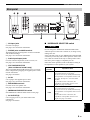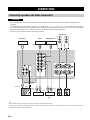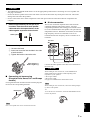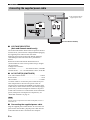
1
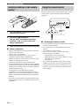
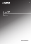
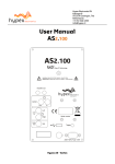
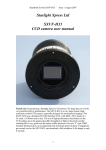
UAB
Integrated Amplifier
Amplificateur Intégré
OWNER’S MANUAL
MODE D’EMPLOI
IMPORTANT SAFETY INSTRUCTIONS
CAUTION
RISK OF ELECTRIC SHOCK
DO NOT OPEN
CAUTION: TO REDUCE THE RISK OF
ELECTRIC SHOCK, DO NOT REMOVE
COVER (OR BACK). NO USER-SERVICEABLE
PARTS INSIDE. REFER SERVICING TO
QUALIFIED SERVICE PERSONNEL.
1
2
3
4
5
6
7
8
9
•
Explanation of Graphical Symbols
The lightning flash with arrowhead symbol, within
an equilateral triangle, is intended to alert you to the
presence of uninsulated “dangerous voltage” within
the product’s enclosure that may be of sufficient
magnitude to constitute a risk of electric shock to
persons.
The exclamation point within an equilateral triangle
is intended to alert you to the presence of important
operating and maintenance (servicing) instructions in
the literature accompanying the appliance.
IMPORTANT
Please record the serial number of this unit in the space
below.
MODEL:
Serial No.:
The serial number is located on the rear of the unit.
Retain this Owner’s Manual in a safe place for future
reference.
FOR CANADIAN CUSTOMERS
To prevent electric shock, match wide blade of plug to
wide slot and fully insert.
This Class B digital apparatus complies with Canadian
ICES-003.
10
11
12
13
14
Read these instructions.
Keep these instructions.
Heed all warnings.
Follow all instructions.
Do not use this apparatus near water.
Clean only with dry cloth.
Do not block any ventilation openings. Install in accordance
with the manufacturer’s instructions.
Do not install near any heat sources such as radiators, heat
registers, stoves, or other apparatus (including amplifiers) that
produce heat.
Do not defeat the safety purpose of the polarized or
grounding-type plug. A polarized plug has two blades with
one wider than the other. A grounding type plug has two
blades and a third grounding prong. The wide blade or the
third prong are provided for your safety. If the provided plug
does not fit into your outlet, consult an electrician for
replacement of the obsolete outlet.
Protect the power cable from being walked on or pinched
particularly at plugs, convenience receptacles, and the point
where they exit from the apparatus.
Only use attachments/accessories specified by the
manufacturer.
Use only with the cart, stand, tripod,
bracket, or table specified by the
manufacturer, or sold with the apparatus.
When a cart is used, use caution when
moving the cart/apparatus combination to
avoid injury from tip-over.
Unplug this apparatus during lightning storms or when unused
for long periods of time.
Refer all servicing to qualified service personnel. Servicing is
required when the apparatus has been damaged in any way,
such as power-supply cable or plug is damaged, liquid has
been spilled or objects have fallen into the apparatus, the
apparatus has been exposed to rain or moisture, does not
operate normally, or has been dropped.
We Want You Listening For A Lifetime
Yamaha and the Electronic Industries Association’s Consumer Electronics Group want you to get the most out of your
equipment by playing it at a safe level. One that lets the sound come through loud and clear without annoying blaring or
distortion – and, most importantly, without affecting your sensitive hearing. Since hearing damage from loud sounds is
often undetectable until it is too late, Yamaha and the Electronic Industries Association’s Consumer Electronics Group
recommend you to avoid prolonged exposure from excessive volume levels.
i En
IMPORTANT SAFETY INSTRUCTIONS
FCC INFORMATION (for US customers)
1 IMPORTANT NOTICE: DO NOT MODIFY THIS
UNIT!
This product, when installed as indicated in the
instructions contained in this manual, meets FCC
requirements. Modifications not expressly approved by
Yamaha may void your authority, granted by the FCC, to
use the product.
2 IMPORTANT: When connecting this product to
accessories and/or another product use only high quality
shielded cables. Cable/s supplied with this product
MUST be used. Follow all installation instructions.
Failure to follow instructions could void your FCC
authorization to use this product in the USA.
3 NOTE: This product has been tested and found to
comply with the requirements listed in FCC Regulations,
Part 15 for Class “B” digital devices. Compliance with
these requirements provides a reasonable level of
assurance that your use of this product in a residential
environment will not result in harmful interference with
other electronic devices.
This equipment generates/uses radio frequencies and, if
not installed and used according to the instructions found
in the users manual, may cause interference harmful to
the operation of other electronic devices.
■ For U.K. customers
Compliance with FCC regulations does not guarantee that
interference will not occur in all installations. If this
product is found to be the source of interference, which
can be determined by turning the unit “OFF” and “ON”,
please try to eliminate the problem by using one of the
following measures:
Relocate either this product or the device that is being
affected by the interference.
Utilize power outlets that are on different branch (circuit
breaker or fuse) circuits or install AC line filter/s.
In the case of radio or TV interference, relocate/reorient
the antenna. If the antenna lead-in is 300 ohm ribbon
lead, change the lead-in to coaxial type cable.
If these corrective measures do not produce satisfactory
results, please contact the local retailer authorized to
distribute this type of product. If you can not locate the
appropriate retailer, please contact Yamaha Electronics
Corp., U.S.A. 6660 Orangethorpe Ave., Buena Park, CA
90620.
The above statements apply ONLY to those products
distributed by Yamaha Corporation of America or its
subsidiaries.
■ Special Instructions for U.K. Model
If the socket outlets in the home are not suitable for the
plug supplied with this appliance, it should be cut off and
an appropriate 3 pin plug fitted. For details, refer to the
instructions described below.
IMPORTANT
THE WIRES IN MAINS LEAD ARE COLOURED IN
ACCORDANCE WITH THE FOLLOWING CODE:
Note
Blue: NEUTRAL
Brown: LIVE
The plug severed from the mains lead must be destroyed, as a
plug with bared flexible cord is hazardous if engaged in a live
socket outlet.
As the colours of the wires in the mains lead of this
apparatus may not correspond with the coloured
markings identifying the terminals in your plug,
proceed as follows:
The wire which is coloured BLUE must be connected
to the terminal which is marked with the letter N or
coloured BLACK. The wire which is coloured
BROWN must be connected to the terminal which is
marked with the letter L or coloured RED.
Making sure that neither core is connected to the earth
terminal of the three pin plug.
ii En
CAUTION: READ THIS BEFORE OPERATING YOUR UNIT.
1 To assure the finest performance, please read this manual
carefully. Keep it in a safe place for future reference.
2 Install this sound system in a well ventilated, cool, dry, clean
place – away from direct sunlight, heat sources, vibration,
dust, moisture, and/or cold. Allow ventilation space of at least
30 cm (11-13/16 in) on the top, 20 cm (7-7/8 in) on the left
and right, and 20 cm (7-7/8 in) on the back of this unit.
3 Locate this unit away from other electrical appliances, motors,
or transformers to avoid humming sounds.
4 Do not expose this unit to sudden temperature changes from
cold to hot, and do not locate this unit in an environment with
high humidity (i.e. a room with a humidifier) to prevent
condensation inside this unit, which may cause an electrical
shock, fire, damage to this unit, and/or personal injury.
5 Avoid installing this unit where foreign objects may fall onto
this unit and/or this unit may be exposed to liquid dripping or
splashing. On the top of this unit, do not place:
– Other components, as they may cause damage and/or
discoloration on the surface of this unit.
– Burning objects (i.e. candles), as they may cause fire,
damage to this unit, and/or personal injury.
– Containers with liquid in them, as they may fall and
liquid may cause electrical shock to the user and/or
damage to this unit.
6 Do not cover this unit with a newspaper, tablecloth, curtain,
etc. in order not to obstruct heat radiation. If the temperature
inside this unit rises, it may cause fire, damage to this unit,
and/or personal injury.
7 Do not plug in this unit to a wall outlet until all connections
are complete.
8 Do not operate this unit upside-down. It may overheat,
possibly causing damage.
9 Do not use force on switches, knobs and/or cords.
10 When disconnecting the power cable from the wall outlet,
grasp the plug; do not pull the cable.
11 Do not clean this unit with chemical solvents; this might
damage the finish. Use a clean, dry cloth.
12 Only voltage specified on this unit must be used. Using this
unit with a higher voltage than specified is dangerous and may
cause fire, damage to this unit, and/or personal injury.
Yamaha will not be held responsible for any damage resulting
from use of this unit with a voltage other than specified.
13 To prevent damage by lightning, keep the power cable
disconnected from a wall outlet or the unit during a lightning
storm.
14 Do not attempt to modify or fix this unit. Contact qualified
Yamaha service personnel when any service is needed. The
cabinet should never be opened for any reasons.
15 When not planning to use this unit for long periods of time
(i.e. vacation), disconnect the AC power plug from the wall
outlet.
16 Install this unit near the AC outlet and where the AC power
plug can be reached easily.
17 Be sure to read the “TROUBLESHOOTING” section in the
owner’s manual on common operating errors before
concluding that this unit is faulty.
18 Before moving this unit, press POWER to turn off this unit
and then disconnect the AC power plug from the wall outlet.
iii En
19 VOLTAGE SELECTOR (Asia and General models only)
The VOLTAGE SELECTOR on the rear panel of this unit
must be set for your local main voltage BEFORE plugging
into the wall outlet. Voltages are:
Asia model.............................. AC 220/230-240 V, 50/60 Hz
General model ..........AC 110/120/220/230-240 V, 50/60 Hz
20 The batteries shall not be exposed to excessive heat such as
sunshine, fire or like.
21 Excessive sound pressure from earphones and headphones
can cause hearing loss.
As long as this unit is connected to the AC wall outlet,
it is not disconnected from the AC power source even
if you turn off this unit by POWER or set it to the
standby mode by button on the remote control.
WARNING
TO REDUCE THE RISK OF FIRE OR ELECTRIC
SHOCK, DO NOT EXPOSE THIS UNIT TO RAIN
OR MOISTURE.
This unit enters the standby mode when you press
POWER inward to the ON position and then press
button on the remote control. In this state, this unit is
designed to consume a very small quantity of power.
CONTENTS
OPERATION
FEATURES............................................................. 1
SUPPLIED ACCESSORIES ................................. 1
CONTROLS AND FUNCTIONS ......................... 2
Playing a source......................................................... 9
Adjusting the tonal quality ...................................... 10
Recording a source .................................................. 11
ADDITIONAL INFORMATION
TROUBLESHOOTING .......................................12
SPECIFICATIONS...............................................15
PREPARATION
CONNECTIONS .................................................... 6
Connecting speakers and other components.............. 6
Connecting the supplied power cable ........................ 8
• y indicates a tip for your operation.
• Some operations can be performed by using either the buttons on the main unit or on the remote control. In cases
when the button names differ between the main unit and the remote control, the names of the buttons on the remote
control are given in parentheses.
• This manual is printed prior to production. Design and specifications are subject to change in part as a result of
improvements, etc. In case of differences between the manual and the product, the product has priority.
FEATURES
◆ Highly dynamic power, low impedance drive capability
◆ Continuously variable loudness control
◆ CD DIRECT AMP switch used to obtain the highest
sound quality of compact discs
◆ PURE DIRECT switch used to reproduce the purest
source sound
◆ Minimum RMS output power
90 W + 90 W (8 Ω), 0.019% THD, 20 Hz to 20 kHz
◆ REC OUT selector independent of input source selection
◆ Remote control capability
ADDITIONAL
INFORMATION
INTRODUCTION
OPERATION
■ About this manual
PREPARATION
Front panel ................................................................. 2
Remote control........................................................... 3
Installing batteries in the remote control ................... 4
Using the remote control ........................................... 4
Rear panel .................................................................. 5
PLAYING AND RECORDING.............................9
INTRODUCTION
INTRODUCTION
SUPPLIED ACCESSORIES
Please check that you received all of the following parts:
Remote control
Batteries (× 2)
(AA, R6, UM-3)
Power cable
English
1 En
CONTROLS AND FUNCTIONS
Front panel
1 POWER
Press inward to the ON position to turn on the power of
this unit. You can set this unit to standby mode by
pressing button on the remote control or turn on the unit
by pressing button on the remote control when this unit is
turned on.
Press again to release it outward to the OFF position to
turn off this unit.
Note
Even when this unit is turned off, this unit consumes a small
amount of power to preserve the memory.
2 POWER on indicator
Lights up as follows:
ON: Bright
Standby mode: Dark
OFF: Off
3 Remote control sensor
Receives signals from the remote control.
4 INPUT selector and indicators
Select the input source you want to listen to.
The input source indicators light up when the
corresponding input sources are selected.
y
The input source names correspond to the names of the
connection jacks on the rear panel.
Note
The input setting is retained for about 1 week after the power
cable is unplugged.
2 En
5 PHONES jack
Connect headphones for private listening.
Rotate the SPEAKERS selector on the front panel to the
OFF position to turn off the sound from the speakers.
6 SPEAKERS selector
Turn on or off the speaker set connected to the
SPEAKERS A and/or B terminals on the rear panel each
time the corresponding SPEAKERS selector is set to A, B
or A+B.
7 REC OUT selector
Select a source for recording independently of the INPUT
selector setting, allowing you to record the selected source
while listening to another source.
See page 11 for details.
8 BASS
Increase or decrease the low frequency response.
See page 10 for details.
9 TREBLE
Increase or decrease the high frequency response.
See page 10 for details.
0 BALANCE
Adjust the sound output balance of the left and right
speakers. See page 10 for details.
A LOUDNESS
Retain a full tonal range at any volume level.
See page 11 for details.
B CD DIRECT AMP and indicator
Reproduces CD sound in the highest signal quality
regardless of the INPUT selector setting.
The indicator above it lights up when this function is
turned on. See page 10 for details.
CONTROLS AND FUNCTIONS
D VOLUME
Control the sound output level.
This does not affect the REC level for recording.
INTRODUCTION
C PURE DIRECT and indicator
Reproduces any input source in the purest sound possible.
The indicator above it lights up when this function is
turned on. See page 10 for details.
Remote control
4 Input selector buttons
Select the input source you want to listen to.
5 Amplifier control buttons
INPUT l / h
Select the input source you want to listen to.
VOL +/–
Control the sound output level.
This does not affect the REC level for recording.
MUTE
Mute the sound output. Press MUTE again to resume the
audio output. Selected Input indicator blinks when the
sound is muted.
■ Controlling other components
The functions of the buttons to control other Yamaha
components are the same as those of the corresponding
buttons on those components. Refer to the components’
instruction manuals for details.
6 Yamaha tuner control buttons
Control various functions of Yamaha tuner. Refer to the
owner’s manual of your tuner for details.
Note
■ Controlling this unit
Not all Yamaha tuners or functions can be controlled by this
remote control.
1 Infrared signal transmitter
Sends signals to the main unit.
7 Yamaha CD player control buttons
Control various functions of Yamaha CD player. Refer to
the owner’s manual of your CD player for details.
2 POWER ( )
Turn on the unit.
Note
Note
Not all Yamaha CD players or functions can be controlled by this
remote control.
This button is operational only when POWER on the front panel
is pressed inward to the ON position.
3 STANDBY ( )
Set this unit to the standby mode.
Notes
English
• This button is operational only when POWER on the front
panel is pressed inward to the ON position.
• In the standby mode, this unit consumes a small amount of
power in order to receive infrared-signals from the remote
control.
3 En
CONTROLS AND FUNCTIONS
Installing batteries in the remote
control
1
Using the remote control
The remote control transmits a directional infrared beam.
Be sure to aim the remote control directly at the remote
control sensor on the front panel of this unit during
operation.
3
2
1
Press the
part and slide the battery
compartment cover off.
2
Insert two supplied batteries
(AA, R6, UM-3) according to the polarity
markings (+ and –) on the inside of the
battery compartment.
3
Slide the cover back until it snaps into place.
■ Notes on batteries
• Change both batteries when the operation range of the
remote control decreases.
• Use AA, R6, UM-3 batteries.
• Make sure that the polarities are correct. See the
illustration inside the battery compartment.
• Remove the batteries if the remote control is not to be
used for an extended period of time.
• Do not use old batteries together with new ones.
• Do not use different types of batteries (such as alkaline
and manganese batteries) together. Read the packaging
carefully as these different types of batteries may have
the same shape and color.
• If the batteries have leaked, dispose of them
immediately. Avoid touching the leaked material or
letting it come into contact with clothing, etc. Clean the
battery compartment thoroughly before installing new
batteries.
• Do not throw away batteries with general house waste;
dispose of them correctly in accordance with your local
regulations.
4 En
Within 6m
(20 ft)
■ Handling the remote control
• The area between the remote control and this unit must
be clear of large obstacles.
• Do not spill water or other liquids on the remote
control.
• Do not drop the remote control.
• Do not leave or store the remote control in the
following types of conditions:
– high humidity, such as near a bath
– high temperature, such as near a heater or a stove
– extremely low temperatures
– dusty places
• Do not expose the remote control sensor to strong
lighting, in particular, an inverter type fluorescent
lamp; otherwise, the remote control may not work
properly. If necessary, position the unit away from
direct lighting.
CONTROLS AND FUNCTIONS
Rear panel
INTRODUCTION
(Asia and General models)
1 CD input jacks
Connect a CD player.
See page 6 for connection information.
■ IMPEDANCE SELECTOR switch
2 PHONO jacks and GND terminal
The PHONO jacks are designed to connect a turntable
with an MM cartridge.
See page 6 for connection information.
Do not change the IMPEDANCE SELECTOR switch
while the power of this unit is turned on, as doing so may
damage the unit.
If the unit fails to turn on, the IMPEDANCE SELECTOR
switch may not be fully slid to either position. If this is the
case, slide the switch all the way to either position when
this unit’s power supply is completely cut off.
Select the switch position (LOW or HIGH) according to
the impedance of the speakers in your system.
3 Audio input/output jacks
Connect external components, such as a tuner, etc.
See page 6 for connection information.
4 VOLTAGE SELECTOR
(Asia and General models only)
The VOLTAGE SELECTOR must be set to your local
main voltage before plugging the supplied power cable
into the wall outlet.
See page 8 for details.
5 AC IN
Use to plug in the supplied power cable.
See page 8 for connection information.
CAUTION
Switch
position
Impedance level
HIGH
• If you use one set (A or B), the impedance of
the speaker must be 6 Ω or higher.
• If you use two sets (A and B) simultaneously,
the impedance of each speaker must be 12 Ω
or higher. (Except for U.S.A and Canada
models)
• If you make bi-wire connections, the
impedance of the speaker must be 6 Ω or
higher. See page 7 for details.
LOW
• If you use one set (A or B), the impedance of
the speaker must be 4 Ω or higher.
• If you use two sets (A and B) simultaneously,
the impedance of each speaker must be 8 Ω or
higher.
• If you make bi-wire connections, the
impedance of the speaker must be 4 Ω or
higher. See page 7 for details.
6 SPEAKERS terminals
Connect one or two speaker sets.
See page 6 for connection information.
7 IMPEDANCE SELECTOR switch
See IMPEDANCE SELECTOR switch on this page.
8 AC OUTLET(S)
Use to supply power to your other audio/video
components.
See page 8 for details.
English
5 En
PREPARATION
CONNECTIONS
Connecting speakers and other components
CAUTION
• Do not connect this unit or other components to the main power until all connections between components are
complete.
• All connections must be correct: L (left) to L, R (right) to R, “+” to “+” and “–” to “–”. If the connections are faulty,
no sound will be heard from the speakers, and if the polarity of the speaker connections is incorrect, the sound will be
unnatural and lack bass. Also, refer to the owner’s manual for each of your components.
• Use RCA stereo cable for audio units except speakers.
Speakers A
Tuner
CD player
Audio out
Audio out
DVD player, etc.
Audio out
Audio out
GND
Audio
out
Turntable
Audio in
Tape deck, etc.
Audio
out
CD recorder,
etc.
Speakers B
y
• The PHONO jacks are designed to connect a turntable with an MM cartridge.
• Connect your turntable to the GND terminal to reduce noise in the signal. However, you may hear less noise without the connection to
the GND terminal for some turntable(s).
6 En
CONNECTIONS
CAUTION
• The IMPEDANCE SELECTOR must be set to the appropriate position before connecting one or two speaker sets.
See page 5 for details.
• Do not let the bare speaker wires touch each other or do not let them touch any metal part of this unit. This could
damage this unit and/or the speakers.
• Do not connect this unit or other components to the main power until all connections between components are
complete.
1
■ Bi-wire connection
10 mm (3/8 in)
The bi-wire connection separates the woofer from the
combined midrange and tweeter section. A bi-wire
compatible speaker has four binding post terminals. These
two sets of terminals allow the speaker to be split into two
independent sections. With these connections, the mid and
high frequency drivers are connected to one set of
terminals and the low frequency driver to another set of
terminals.
PREPARATION
Remove approximately 10 mm (3/8 in) of
insulation from the end of each speaker
cable and twist the exposed wires of the
cable together to prevent short circuits.
This unit
2
Speaker
Connect the speaker cable.
1 Unscrew the knob.
2 Insert one bare wire into the hole in the side
of each terminal.
3 Tighten the knob to secure the wire.
Red: positive (+)
Black: negative (–)
Connect the other speaker to the other set of terminals in
the same way.
CAUTION
■ Connecting via banana plug
(Except for Asia, Korea, U.K. and Europe
models)
First, tighten the knob and then insert the banana plug into
the end of the corresponding terminal.
When making bi-wire connections, set the IMPEDANCE
SELECTOR switch to HIGH or LOW depending on the
impedance of your speakers:
6 Ω or higher: HIGH
4 Ω or higher: LOW
See page 5 for IMPEDANCE SELECTOR switch.
Note
When making bi-wire connections, remove the shorting bridges
or cables on the speaker.
Banana plug
y
To use the bi-wire connections, switch the SPEAKERS selector
to the A+B position.
English
Note
One or two speaker sets can be connected to this unit.
7 En
CONNECTIONS
Connecting the supplied power cable
To the wall outlet with the
supplied power cable
(Asia and General models)
■ VOLTAGE SELECTOR
(Asia and General models only)
The VOLTAGE SELECTOR on the rear panel of this unit
must be set for your local main voltage BEFORE plugging
the supplied power cable into the wall outlet.
Improper setting of the VOLTAGE SELECTOR may
cause damage to this unit and create a potential fire
hazard.
Rotate the VOLTAGE SELECTOR clockwise or
counterclockwise to the correct position using a straight
slot screwdriver.
Voltages are as follows:
Asia model.......................... AC 220/230–240 V, 50/60 Hz
General model ......AC 110/120/220/230–240 V, 50/60 Hz
■ AC OUTLET(S) (SWITCHED)
U.K. and Australia models ..................................... 1 outlet
Korea model .............................................................. None
Other models ........................................................ 2 outlets
Use these outlets to connect the power cables from your
other components to this unit. The power to the AC
OUTLET(S) is controlled by POWER on the front panel
of this unit (or on the remote control). The outlet(s) supply
power to any connected component whenever the power
of this unit is turned on. For information on the maximum
power (total power consumption of components), see
“SPECIFICATIONS” on page 15.
Note
Do not connect components with a built-in amplifier, such as a
subwoofer, etc.
■ Connecting the supplied power cable
Plug the supplied power cable into the AC IN on the rear
panel of this unit and then, plug the power cable into the
wall outlet after all other connections are complete.
8 En
OPERATION
PLAYING AND RECORDING
Playing a source
3
Rotate the INPUT selector on the front panel
(or press one of the input selector buttons on
the remote control) to select the input source
you want to listen to.
The indicator of the selected input source lights up.
or
Front panel
Remote control
Lights up
OPERATION
4
1
Rotate the SPEAKERS selector on the front
panel to select SPEAKERS A, B or A+B.
Rotate VOLUME on the front panel to the
extreme counterclockwise position.
Notes
• Switch the SPEAKERS selector to the A+B position when
making bi-wire connections, or when using two sets of speakers
simultaneously (A and B).
• If you listen with headphones, rotate the selector to the OFF
position.
2
5
Play the source.
Press POWER on the front panel inward to
the ON position.
English
9 En
PLAYING AND RECORDING
6
■ Using the PURE DIRECT switch
Rotate VOLUME on the front panel (or press
VOL +/– on the remote control) to adjust the
sound output level.
Routes input signals from your audio sources. As a result,
the input signals bypass the BASS, TREBLE, BALANCE
and LOUDNESS controls, thus eliminating any alterations
to the audio signals to produce more direct and high-grade
sound from all input sources.
Lights up
or
Front panel
Remote control
y
You can adjust the tonal quality by using the BASS, TREBLE,
BALANCE and LOUDNESS controls, the CD DIRECT AMP
switch, or the PURE DIRECT switch on the front panel.
7
After using, press POWER on the front panel
to turn off the power.
y
You can turn on the power by pressing the button on the remote
control if you set this unit to standby mode by pressing the
button on the remote control.
Note
The BASS, TREBLE, BALANCE and LOUDNESS controls do
not function while the PURE DIRECT switch is turned on.
■ Adjusting the BASS and TREBLE
controls
Adjust the high and low frequency response.
The center position produces a flat response.
BASS
When you feel a lack of bass sound, rotate clockwise to
boost. When you feel excessive bass sound, rotate
counterclockwise to suppress.
Control range: –10 dB to +10 dB (20 Hz)
TREBLE
When you feel a lack of treble sound, rotate clockwise to
boost. When you feel excessive treble sound, rotate
counterclockwise to suppress.
Control range: –10 dB to +10 dB (20 kHz)
Adjusting the tonal quality
■ Using the CD DIRECT AMP switch
Routes input signals directly to the power amplifier from
your CD player, regardless of the INPUT selector setting.
As a result, the input signals bypass the INPUT selector
and the BASS, TREBLE, BALANCE and LOUDNESS
controls. The gain is also adjusted appropriately for CD so
that the purest possible sound is reproduced without any
alterations to the CD signals.
Lights up
Notes
• The BASS, TREBLE, BALANCE, LOUDNESS controls and
INPUT selector do not function while the CD DIRECT AMP
switch is turned on.
• Be sure to connect the CD player to the CD input jacks if you
use the CD DIRECT AMP switch.
10 En
■ Adjusting the BALANCE control
Adjust the sound output balance of the left and right
speakers to compensate for sound imbalance caused by
speaker locations or listening room conditions.
PLAYING AND RECORDING
■ Adjusting the LOUDNESS control
Retain a full tonal range at any volume level, thus
compensating for the human ears’ loss of sensitivity to
high and low-frequency ranges at low volume.
CAUTION
If the CD DIRECT AMP switch (or the PURE DIRECT
switch) is turned on with the LOUDNESS control set at a
certain level, the input signals bypass the loudness control,
resulting in a sudden increase in the sound output level. To
prevent your ears or the speakers from being damaged, be
sure to press the CD DIRECT AMP switch (or the PURE
DIRECT switch) AFTER lowering the sound output level
or AFTER checking that the LOUDNESS control is
properly set.
Set the LOUDNESS control to the FLAT
position.
2
Rotate VOLUME on the front panel (or press
VOL +/– on the remote control) to set the
sound output level to the loudest listening
level that you would listen to.
Notes
• The audio signals are not output via the LINE 2 REC or LINE 3
REC output jacks when LINE 2 or LINE 3 is selected with the
REC OUT selector.
The audio signals are output at both LINE 2 REC and LINE 3
REC output jacks if you select PHONO, TUNER, CD or LINE
1.
• The VOLUME, BASS, TREBLE, BALANCE and
LOUDNESS controls and the CD DIRECT AMP switch (and
the PURE DIRECT switch) have no effect on the source being
recorded.
• Check the copyright laws in your country to record from
records, CDs, radio, etc. Recording copyright-protected
material may infringe on copyright laws.
OPERATION
1
Recording a source
1
Rotate the REC OUT selector on the front
panel to select the source you want to
record.
2
Play the source and begin recording on
recording device connected to the REC
output jacks (LINE 2 and/or LINE 3) on the
rear panel. See page 6.
or
Front panel
3
Remote control
Rotate the LOUDNESS control until the
desired volume is obtained.
y
• If you select the same source with the INPUT selector as you
select with the REC OUT selector, you can monitor the
recording.
• To listen to another input source without affecting the current
record out signal, select the source with the INPUT selector.
y
After setting the LOUDNESS control, enjoy listening to music at
your preferred volume level by controlling VOLUME. If the
effect of the loudness control is too strong or weak, readjust the
LOUDNESS control.
English
11 En
ADDITIONAL INFORMATION
TROUBLESHOOTING
Refer to the chart below if this unit does not function properly. If the problem you are experiencing is not listed below or
if the instructions below do not help, set this unit to the standby mode, disconnect the power cable, and contact the
nearest authorized Yamaha dealer or service center.
■ General
Possible Causes
Pressing the POWER
switch on the front
panel does not turn
on this unit. The
POWER on indicator
also does not light up.
The supplied power cable is not connected
or the cable is not completely inserted.
Connect the supplied power cable firmly.
The POWER ( ) button is pressed on the
remote control while this unit is turned
off.
Press POWER on the front panel to ON.
There is a problem with the internal
circuitries of this unit.
Disconnect the AC power cable and contact the
nearest authorized Yamaha dealer or service center. If
an unusual odor or noise is generated from the unit,
do not turn on the power, disconnect the AC power
cable, and contact a service center for repair.
—
Connect the speaker cables properly and press the
power button ON again. The VOLUME is decreased
automatically and this unit is turned on after the
INPUT indicator blinks for about 15 seconds.
Confirm normal sound output from speakers by
increasing the volume gradually, then you can operate
this unit normally.
7
Replace the speaker set and press the power button
ON again. The VOLUME is decreased automatically
and this unit is turned on after the INPUT indicator
blinks for about 15 seconds. Confirm normal sound
output from speakers by increasing the volume
gradually, then you can operate this unit normally.
—
The protection circuitry has been activated
because of excessive input or excessive
volume level.
Rotate the VOLUME control on the front panel to
decrease the volume level and then turn the power on
again.
—
The protection circuitry has been activated
due to excessive internal temperature.
Allow about 30 minutes for the temperature inside
this unit to decrease, rotate the VOLUME control on
the front panel to lower the volume and then turn the
power on again. Set the unit in a place where heat can
readily dissipate from the unit.
—
The IMPEDANCE SELECTOR switch
may not be fully slid to either position.
Turn the power off and slide the IMPEDANCE
SELECTOR switch all the way to either position.
5
The impedance setting is incorrect.
Set the impedance to match your speakers.
5
This unit has been exposed to a strong
external electric shock (such as lightning
or strong static electricity).
Set this unit to the standby mode, disconnect the
power cable, plug it back in after 30 seconds, then use
it normally.
—
There is a problem with the internal
circuitries of this unit.
Disconnect the AC power cable and contact the
nearest authorized Yamaha dealer or service center. If
an unusual odor or noise is generated from the unit,
do not turn on the power, disconnect the AC power
cable, and contact a service center for repair.
—
The power of this unit
is turned off suddenly
and the POWER on
indicator blinks.
This unit is turned off
after several seconds
of turning on, and the
POWER on indicator
blinks.
12 En
The speaker wires are touching each other
or shorting out against the rear panel.
The speaker is a malfunction.
Solutions
Refer to
page
Problems
8
3
TROUBLESHOOTING
Problems
Possible Causes
Solutions
Refer to
page
Sound is muted.
Press MUTE on the remote control to resume the
audio output.
3
Incorrect cable connections.
Connect the stereo cable for audio units and the
speaker wires properly. If the problem persists, the
cables may be defective.
6
No appropriate input source has been
selected.
Select an appropriate input source with the INPUT
selector on the front panel (or one of the input
selector buttons on the remote control).
9
The SPEAKERS selector is not set
properly.
Set the corresponding SPEAKERS selector to A, B or
A+B position.
9
The protection circuitry has been activated
because of a short circuit, etc.
Check that the IMPEDANCE SELECTOR setting is
correct.
5
Check that the speaker wires are not touching each
other or shorting out against the rear panel of this
unit, and then turn the power of this unit back on.
6
Incorrect cable connections.
Connect the cables properly. If the problem persists,
the cables may be defective.
6
Incorrect setting for the BALANCE
control.
Set the BALANCE control to the appropriate
position.
10
There is a lack of
bass and no
ambience.
The + and – wires are connected in
reverse at the amplifier or the speakers.
Connect the speaker wires to the correct + and –
phase.
A “humming” sound
can be heard.
Incorrect cable connections.
Connect the audio plugs firmly. If the problem
persists, the cables may be defective.
6
No connection from the turntable to the
GND terminal.
Make the GND connection between the turntable and
this unit.
6
The turntable is connected to the jacks
other than the PHONO jacks.
Connect the turntable to the PHONO jacks.
The record is being played on a turntable
with an MC cartridge.
Use a turntable equipped with an MM cartridge.
The volume level
cannot be increased,
or the sound is
distorted.
The component connected to LINE 2 REC
or LINE 3 REC terminals of this unit is
turned off.
Turn on the power of the component.
The sound is
degraded when
listening with the
headphones
connected to the CD
player or the tape
deck connected to
this unit.
The power of this unit is turned off, or this
unit is set to the standby mode.
Turn on the power of this unit.
The sound level is
low.
The LOUDNESS control is functioning.
Set the LOUDNESS control to the FLAT position.
The input source
cannot be changed
although the INPUT
selector is rotated.
The CD DIRECT AMP switch is turned
on.
Turn off the CD DIRECT AMP switch.
Using the BASS,
TREBLE, BALANCE
and LOUDNESS
controls does not
affect the tonal
quality.
The CD DIRECT AMP switch or the
PURE DIRECT switch is turned on.
The CD DIRECT AMP switch or the PURE DIRECT
switch must be turned off to use those controls.
No sound
The sound suddenly
goes off.
Only the speaker on
one side can be
heard.
6
—
ADDITIONAL
INFORMATION
The volume level is
low while playing a
record.
6
—
9
11
10
13 En
English
10
TROUBLESHOOTING
■ Remote control
Problems
The remote control
does not work nor
function properly.
14 En
Solutions
Refer to
page
The remote control is too far away or
tilted too much.
The remote control will function within a maximum
range of 6 m (20 ft) and no more than 30 degrees offaxis from the front panel.
4
Direct sunlight or lighting (from an
inverter type of fluorescent lamp, etc.) is
striking the remote control sensor of this
unit.
Reposition this unit or lightning.
The batteries are weak.
Replace all batteries.
Possible Causes
—
4
SPECIFICATIONS
POWER SECTION
CONTROL SECTION
• Minimum RMS output power
(8 Ω, 20 Hz to 20 kHz, 0.019% THD)...................... 90 W + 90 W
(6 Ω, 20 Hz to 20 kHz, 0.03% THD).................... 105 W + 105 W
• Input Sensitivity/Input Impedance
PHONO .................................................................. 3.0 mV/47 kΩ
CD, etc. .................................................................. 200 mV/47 kΩ
• Dynamic Power (IHF)
(8/6/4/2 Ω) ...................................................... 135/160/200/240 W
• Output Level/Output Impedance
REC level ................................................... 200 mV/1.2 kΩ or less
• Maximum Output Power
[Europe model only]
(1 kHz, 0.7% THD, 4 Ω) ................................................... 160 W
[Asia and General models only] (JEITA)
(1 kHz, 10% THD, 8/6 Ω) .......................................... 140/160 W
• Headphone Output/Impedance
(Input 1 kHz, 200 mV, 8 Ω, 0.015% THD)
CD, etc. ................................................................ 0.47 V/470 Ω
• IEC Output Power [Europe model only]
(1 kHz, 0.019% THD, 8 Ω) ................................................. 105 W
• Power Band Width
(0.03% THD, 50 W, 8 Ω) .................................... 10 Hz to 50 kHz
• Damping Factor
1 kHz, 8 Ω ................................................................... 240 or more
• Maximum Input Signal
PHONO (1 kHz, 0.019% THD) ............................ 70 mV or more
CD, etc. (1 kHz, 0.019% THD) .............................. 2.2 V or more
• Frequency Response
CD, etc. (20 Hz to 20 kHz) ........................................... 0 ± 0.5 dB
CD DIRECT AMP ON (10 Hz to 100 kHz) ................. 0 ± 1.0 dB
• RIAA Equalization Deviation
PHONO ............................................................................ ± 0.5 dB
• Signal to Noise Ratio (IHF-A Network)
PHONO (5 mV input shorted) ................................ 87 dB or more
CD DIRECT AMP (200 mV input shorted) .......... 110 dB or more
• Residual Noise (IHF-A Network)
CD DIRECT AMP ON ....................................................... 30 µV
PURE DIRECT ON .......................................................... 110 µV
• Gain Tracking Error (0 to –60 dB) ..................................2 dB or less
• Tone Control Characteristics
BASS
Boost/Cut (20 Hz) .......................................................... ±10 dB
Turnover Frequency ........................................................ 350 Hz
TREBLE
Boost/Cut (20 kHz) ........................................................ ±10 dB
Turnover Frequency ....................................................... 3.5 kHz
• Continuous Loudness Control
Attenuation (1 kHz) ............................................................ –30 dB
GENERAL
• Power Supply
[U.S.A. and Canada models] ............................. AC 120 V, 60 Hz
[Asia model] .................................. AC 220/230–240 V, 50/60 Hz
[General model] .............. AC 110/120/220/230–240 V, 50/60 Hz
[China model]...................................................... AC 220 V, 50 Hz
[Korea model] ..................................................... AC 220 V, 60 Hz
[Australia model] .............................................. AC 240 V, 50 Hz
[U.K. and Europe models] ................................ AC 230 V, 50 Hz
• Power Consumption
[U.S.A. and Canada models] ................................ 260 W, 360 VA
[Other models] ................................................................... 260 W
• Standby Power Consumption .................................................. 0.1 W
ADDITIONAL
INFORMATION
• Total Harmonic Distortion
PHONO to OUT (REC)
(20 Hz to 20 kHz, 3 V) ......................................... 0.008% or less
CD, etc. to SP OUT
(20 Hz to 20 kHz, 50 W, 8 Ω) ............................... 0.012% or less
• Channel Separation
CD, etc. (5.1 kΩ input shorted, 1/10 kHz) ........ 65/50 dB or more
• Maximum Power Consumption [General model only]
(6 Ω, 1 kHz, 10% THD)...................................................... 650 W
• AC Outlets
[U.K. and Australia models] .............. 1 (Total 100 W maximum)
[Korea model] ....................................................................... None
[General model] ..................................... 2 (Total 50 W maximum)
[Other models] ................................... 2 (Total 100 W maximum)
• Dimensions (W × H × D) ................................ 435 × 151 × 382 mm
(17-1/8 in × 5-15/16 in × 15-1/16 in)
• Weight ..................................................................... 10.9 kg (24 lbs.)
Specifications are subject to change without notice.
English
15 En
Limited Guarantee for European Economic Area (EEA) and Switzerland
Thank you for having chosen a Yamaha product. In the unlikely event that your Yamaha product needs guarantee service, please contact the dealer from
whom it was purchased. If you experience any difficulty, please contact Yamaha representative office in your country. You can find full details on our
website (http://www.yamaha-hifi.com/ or http://www.yamaha-uk.com/ for U.K. resident).
The product is guaranteed to be free from defects in workmanship or materials for a period of two years from the date of the original purchase. Yamaha
undertakes, subject to the conditions listed below, to have the faulty product or any part(s) repaired, or replaced at Yamaha’s discretion, without any charge
for parts or labour. Yamaha reserves the right to replace a product with that of a similar kind and/or value and condition, where a model has been
discontinued or is considered uneconomic to repair.
Conditions
1. The original invoice or sales receipt (showing date of purchase, product code and dealer’s name) MUST accompany the defective product, along with a
statement detailing the fault. In the absence of this clear proof of purchase, Yamaha reserves the right to refuse to provide free of charge service and the
product may be returned at the customer’s expense.
2. The product MUST have been purchased from an AUTHORISED Yamaha dealer within the European Economic Area (EEA) or Switzerland.
3. The product must not have been the subject of any modifications or alterations, unless authorised in writing by Yamaha.
4. The following are excluded from this guarantee:
a. Periodic maintenance and repair or replacement of parts due to normal wear and tear.
b. Damage resulting from:
(1) Repairs performed by the customer himself or by an unauthorised third party.
(2) Inadequate packaging or mishandling, when the product is in transit from the customer. Please note that it is the customer’s responsibility to
ensure the product is adequately packaged when returning the product for repair.
(3) Misuse, including but not limited to (a) failure to use the product for its normal purpose or in accordance with Yamaha’s instructions on the
proper use, maintenance and storage, and (b) installation or use of the product in a manner inconsistent with the technical or safety standards in
force in the country where it is used.
(4) Accidents, lightning, water, fire, improper ventilation, battery leakage or any cause beyond Yamaha’s control.
(5) Defects of the system into which this product is incorporated and/or incompatibility with third party products.
(6) Use of a product imported into the EEA and/or Switzerland, not by Yamaha, where that product does not conform to the technical or safety
standards of the country of use and/or to the standard specification of a product sold by Yamaha in the EEA and/or Switzerland.
(7) Non AV (Audio Visual) related products.
(Products subject to “Yamaha AV Guarantee Statement” are defined in our website at http://www.yamaha-hifi.com/ or
http://www.yamaha-uk.com/ for U.K. resident.)
5. Where the guarantee differs between the country of purchase and the country of use of the product, the guarantee of the country of use shall apply.
6. Yamaha may not be held responsible for any losses or damages, whether direct, consequential or otherwise, save for the repair or replacement of the
product.
7. Please backup any custom settings or data, as Yamaha may not be held responsible for any alteration or loss to such settings or data.
8. This guarantee does not affect the consumer’s statutory rights under applicable national laws in force or the consumer’s rights against the dealer arising
from their sales/purchase contract.
■ For U.K. customers
Information for Users on Collection and Disposal of Old Equipment
and Used Batteries
These symbols on the products, packaging, and/or accompanying documents mean that used electrical and
electronic products and batteries should not be mixed with general household waste.
For proper treatment, recovery and recycling of old products and used batteries, please take them to
applicable collection points, in accordance with your national legislation and the Directives 2002/96/EC
and 2006/66/EC.
By disposing of these products and batteries correctly, you will help to save valuable resources and prevent
any potential negative effects on human health and the environment which could otherwise arise from
inappropriate waste handling.
For more information about collection and recycling of old products and batteries, please contact your
local municipality, your waste disposal service or the point of sale where you purchased the items.
[Information on Disposal in other Countries outside the European Union]
These symbols are only valid in the European Union. If you wish to discard these items, please contact
your local authorities or dealer and ask for the correct method of disposal.
Note for the battery symbol (bottom two symbol examples):
This symbol might be used in combination with a chemical symbol. In this case it complies with the
requirement set by the Directive for the chemical involved.
Garantie Limitée pour l’Espace Économique Européenne et la Suisse
Merci d’avoir porté votre choix sur un produit Yamaha. Dans l’hypothèse où vous devriez recourir au service de notre garantie après-vente, veuillez
contacter votre revendeur Yamaha. Si vous rencontrez la moindre difficulté, n’hésitez pas à contacter directement Yamaha dans votre pays de résidence.
Vous pouvez trouver toutes informations complémentaires sur notre site Web (http://www.yamaha-hifi.com/ ou http://www.yamaha-uk.com/ pour les
résidents au Royaume-Uni).
Yamaha garantit votre produit contre tout défaut de fabrication, pièces et main d’oeuvre, pour une durée de 2 ans à compter de la première date de vente au
détail. Yamaha s’engage, dans les conditions décrites ci-après, à procéder à la réparation du produit défectueux (ou d’un quelconque de ses composants) ou
à son remplacement à l’appréciation de Yamaha en prenant à sa charge les coûts relatifs aux pièces détachées et à la main d’oeuvre. Yamaha se réserve le
droit de remplacer le produit par un modèle semblable, de par sa valeur et ses caractéristiques, dès lors que la commercialisation dudit produit a cessé ou
bien lorsque sa réparation s’avère économiquement injustifiée.
Conditions
1. La facture d’achat originelle ou un justificatif d’achat correspondant (indiquant la date d’achat, la référence du produit et le nom du revendeur) DOIT
accompagner le produit défectueux, ainsi qu’une description précise du dysfonctionnement constaté. En l’absence de cette preuve d’achat, Yamaha se
réserve le droit de refuser le service de la garantie et le produit peut être restitué aux frais du consommateur.
2. Le produit DOIT avoir été acheté par un distributeur agréé Yamaha au sein de l’Espace Economique Européen ou en Suisse.
3. Le produit doit n’avoir fait l’objet d’aucune modification ou altération, sauf accord écrit de Yamaha.
4. Les cas suivants font obstacle à l’application de la garantie :
a. Entretien périodique et réparation ou remplacement de pièces ayant subi une usure ou défaillance normale.
b. Dommages résulótant de :
(1) Réparation effectuée par le consommateur lui-même ou par un tiers non autorisé.
(2) Emballage ou manutention inadéquats lors du transport du produit pour réparation. Veuillez noter qu’il est de la responsabilité de l’expéditeur de
s’assurer que le produit est correctement emballé.
(3) Utilisation non-conforme du produit, correspondant aux cas non limitatifs (a) d’utilisation non-conforme à l’objet normal du produit ou
nonconforme aux instructions d’utilisation, de maintenance ou d’installation publiées par Yamaha, (b) ou d’utilisation du produit incompatible
avec les normes techniques ou de sécurité en vigueur au sein du pays d’utilisation.
(4) Accidents, foudre, dégât des eaux, incendie, ventilation incorrecte, fuite de pile ou toute autre cause échappant au contrôle de Yamaha.
(5) Les défauts de la configuration dans laquelle ce produit est incorporé et/ou l’incompatibilité avec des produits tiers.
(6) Produit importé au sein de l’EEE , et/ou en Suisse, par une autre entité que Yamaha, dès lors que ce produit n’est pas conforme aux norms
techniques ou de sécurité du pays d’utilisation et/ou aux normes des produits commercialisés par Yamaha au sein de l’EEE et/ou en Suisse.
(7) Produits non audiovisuels.
(Les produits soumis à une « Déclaration de Garantie AV de Yamaha » sont indiqués sur notre site Web à l’adresse
http://www.yamaha-hifi.com/ ou http://www.yamaha-uk.com/ pour les résidents au Royaume-Uni.)
5. Lorsque la garantie diffère entre le pays d’achat et le pays d’utilisation du produit, la garantie du pays d’utilisation est applicable.
6. Yamaha ne saurait être tenu pour responsable de quelconques pertes ou dommages, directs, consécutifs ou autres, sa responsabilité au titre de la
garantie étant strictement limitée à la réparation ou au remplacement du produit.
7. Nous vous invitons à sauvegarder toutes les données ou réglages personnalisés de votre produit, Yamaha ne pouvant être tenu responsable de leur
modification ou perte.
8. La présente garantie laisse intégralement subsister les droits que le consommateur peut détenir au titre de la garantie légale en vigueur ou au titre du
contrat de vente conclu avec son revendeur.
■
Pour la clientèle au Royaume-Uni
Information concernant la Collecte et le Traitement des piles usagées et
des déchets d’équipements électriques et électroniques
Les symboles sur les produits, l’emballage et/ou les documents joints signifient que les produits
électriques ou électroniques usagés ainsi que les piles ne doivent pas être mélangés avec les déchets
domestiques habituels.
Pour un traitement, une récupération et un recyclage appropriés des déchets d’équipements électriques
et électroniques et des piles usagées, veuillez les déposer aux points de collecte prévus à cet effet,
conformément à la réglementation nationale et aux Directives 2002/96/EC et 2006/66/EC.
En vous débarrassant correctement des déchets d’équipements électriques et électroniques et des piles
usagées, vous contribuerez à la sauvegarde de précieuses ressources et à la prévention de potentiels
effets négatifs sur la santé humaine qui pourraient advenir lors d’un traitement inapproprié des déchets.
Pour plus d’informations à propos de la collecte et du recyclage des déchets d’équipements électriques
et électroniques et des piles usagées, veuillez contacter votre municipalité, votre service de traitement
des déchets ou le point de vente où vous avez acheté les produits.
[Information sur le traitement dans d’autres pays en dehors de l’Union
Européenne]
Ces symboles sont seulement valables dans l’Union Européenne. Si vous souhaitez vous débarrasser de
déchets d’équipements électriques et électroniques ou de piles usagées, veuillez contacter les autorités
locales ou votre fournisseur et demander la méthode de traitement appropriée.
Note pour le symbole « pile » (deux exemples de symbole ci-dessous) :
Ce symbole peut être utilisé en combinaison avec un symbole chimique. Dans ce cas il respecte les
exigences établies par la Directive pour le produit chimique en question.
© 2008 Yamaha Corporation All rights reserved.
Printed in Malaysia
WQ01790