1
Reference Manual
EN
Contents
Introduction............................................. 3
LAST MEMORY RESUME setting
(“5. Utility” ➝ “Last Mem. Resume”) ................ 15
About the documentation .................................3
Clock setting (“5. Utility” ➝ “Clock”)....................... 15
Supported amplifiers .........................................3
GPI IN calibration
(“5. Utility” ➝ “GPI Calibration”) ....................... 16
Setup ...................................................................3
Terms ..................................................................4
Network settings (“6. Network Setup”) ..........16
IP Address Mode setting
(“6. Network Setup” ➝ “IP Address Mode”) ..... 16
Controls and Connectors ...................... 5
IP Address setting
(“6. Network Setup” ➝ “IP Address”) ............... 16
Front Panel .........................................................5
Checking the MAC address
(“6. Network Setup” ➝ “MAC Address”) .......... 16
Rear Panel ..........................................................6
Port settings for an external controller
(“6. Network Setup” ➝ “IP Ctrl Port #”) ............ 17
Panel operations .................................... 7
Initializing the ACD1 ........................................17
Basic operation ..................................................8
Scene (“1. Scene”)...........................................10
Recalling a scene (“1. Scene” ➝ “Recall”) ............ 10
Storing a scene (“1. Scene” ➝ “Store”)................. 10
Controlling an amplifier (“2. Amp Control”)..11
Power on/standby
(“2. Amp Control” ➝ “Standby”) ....................... 11
Mute (“2. Amp Control” ➝ “Mute”)......................... 11
Attenuator value adjustment
(“2. Amp Control” ➝ “Attenuation”) .................. 11
Euroblock plug connection.............................18
GPI connector ..................................................19
FAULT OUTPUT connector .............................20
Appendix ............................................... 21
Display messages............................................21
Amplifier output monitor
(“3. Output Monitor”) .......................................12
List of supported characters ..........................21
Amplifier output (“3. Output Monitor”) ................... 12
Troubleshooting...............................................22
Device setup (“4. Device Setup”) ...................12
Specifications...................................................22
Device ID setting
(“4. Device Setup” ➝ “Device ID”) ................... 12
Control I/O ........................................................23
View ACD1 name
(“4. Device Setup” ➝ “Device Label”) .............. 12
Pin Assignment................................................23
MONITOR/REMOTE............................................. 23
Identify (“4. Device Setup” ➝ “Identify”) ................ 13
DATA PORT .......................................................... 23
Utility (“5. Utility”) ............................................13
Dimensions.......................................................24
Backup battery check (“5. Utility” ➝ “Battery”) ...... 13
Version indication (“5. Utility” ➝ “Firmware Ver.”) .. 13
LCD backlight (“5. Utility” ➝ “LCD Backlight”)....... 14
Restricting panel operations
(“5. Utility” ➝ “Panel Operation”) ..................... 14
Enabling scene recall operations from the panel
(“5. Utility” ➝ “Scene Recall”) .......................... 14
Enabling scene recall operations via
EMG commands
(“5. Utility” ➝ “EMG Scene Setup”) ................. 15
2
Connector wiring .................................. 18
ACD1 Reference Manual
Introduction
About the documentation
This document explains mainly the operation and specifications of the ACD1 amplifier control device itself. When
using the ACD1, you will also need to consult various manuals other than this document.
● Manuals other than this document
ACD1 Owner’s Manual (printed)
Primarily explains initial connections
Amp Editor Installation Guide (PDF)
Explains the installation procedure for Amp Editor, and the uninstallation procedure
Amp Editor Owner’s Manual (PDF)
Explains how to set up the ACD1 and Amp Editor and to use Amp Editor
NOTE
• Please use Amp Editor Version 1.1 or later.
PDF manuals and Amp Editor can be downloaded from the following URL.
http://www.yamahaproaudio.com/downloads/
NOTE
• In order to view the downloaded manuals, Adobe Reader must be installed in your computer. If you don’t have
Adobe Reader, please access the Adobe Corporation’s website at the following URL, and download Adobe Reader
(free of charge).
http://www.adobe.com/
Supported amplifiers
As of September 2009, the following amplifiers support connection with the ACD1.
• XP series
• XM series
• XH series
• PC-N series
• Tn series
:
:
:
:
:
XP7000, XP5000, XP3500, XP2500, XP1000
XM4180, XM4080
XH200
PC9501N, PC6501N, PC4801N, PC3301N, PC2001N, PC9500N, PC4800N, PC3300N
T5n, T4n, T3n
* For the most recent information, refer to the following URL.
http://www.yamahaproaudio.com/
Setup
For details on setting up the ACD1 and Amp Editor, refer to the “Amp Editor Owner’s Manual.”
The “Amp Editor Owner’s Manual” can be downloaded from the download page of the following website.
http://www.yamahaproaudio.com/downloads/
ACD1 Reference Manual
3
Introduction
Terms
This section explains terminology specific to the ACD1.
■ Amp Editor
This is computer application software. With this software, you can use your computer to monitor and control the ACD1 and
the amplifiers connected to the ACD1.
■ Scene
Settings such as Power-On/Standby or mute for each amplifier are collectively called a “scene.” By recalling a scene, the
saved settings can be immediately applied to the amplifiers. The ACD1 can specify 49 scenes for each connected amplifier.
■ Scene link
Settings for simultaneously recalling scenes for multiple amplifiers within an area are called a “scene link.” By recalling a
scene link, scenes can be simultaneously recalled for multiple amplifiers. Scene links can be created and recalled using
Amp Editor.
■ Device ID
This is an ID for uniquely identifying an ACD1 unit within a network. If there are duplicate IDs within an area, it will be
impossible to monitor/control them from Amp Editor.
■ Amp ID
This is the ID of each amplifier connected to the ACD1. Amplifiers connected to the [DATA PORT] connector of the same
ACD1 must be set to non-overlapping IDs using the [AMP ID] switch located on the rear panel of each amplifier. For amplifiers connected to a [MONITOR/REMOTE] connector, the Amp ID is determined by the connector that is used.
4
ACD1 Reference Manual
Controls and Connectors
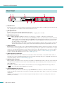
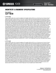
Front Panel
q
w e r
t
q Display
This shows information about the scene, the ACD1 itself, or the connected amplifiers. This will light red when an abnormality (a WARNING or higher alert) occurs. This will also blink blue and white when the Identify operation is performed in
Amp Editor.
When you turn on the power, a HOME screen like the following will appear. The HOME screen shows the Device ID and
the name of the ACD1 specified by Amp Editor.
YAMAHA ACD1
001:FOH #1
Device ID
Device Label ....... The name of the ACD1 assigned by Amp Editor is displayed.
If characters not supported by the ACD1 are used, “ ~ ” will be
displayed in those locations.
w [BACK] button
Use this to move to the previous screen or parameter.
NOTE
• If you press and hold down this button for three seconds or longer while the HOME screen is displayed, the Device ID
setting screen will appear.
e [▲INC/YES]/[▼DEC/NO] buttons
Use these to increment or decrement (INC/DEC) the value of a parameter, or to respond YES/NO to a confirmation message.
NOTE
• To temporarily unlock the panel operation, press and hold down both the [▲INC/YES] and [▼DEC/NO] buttons for at
least three seconds to display the message “Unlock panel: Are you sure?”. Press the [▲INC/YES] button. The panel lock
will be temporarily defeated until the power to the ACD1 is turned off.
• To reset the FAULT OUTPUT connector output (to connect NC and C), press and hold down the [BACK] and [▼DEC/NO]
buttons simultaneously for a few seconds while the HOME screen is displayed to display the message “Reset FaultOut
Are you sure?”. Then press the [▲INC/YES] button. This operation is effective only when the FAULT OUTPUT connector
indicates an abnormality.
r [NEXT] button
Use this to move to the next screen or parameter.
t [POWER ON/OFF] button
Turns mains power to the ACD1 on and off.
NOTE
• The settings at the time you powered-off are remembered. When you turn on the power again, the unit will start up with
the same settings. You can use the “Last Mem. Resume” setting to set up the unit so that at startup it will recall the scene
number selected before you turned off the power to the device.
• If Last Mem. Resume is ON, data will be backed-up to internal memory at regular intervals, so you should not turn off the
power within five seconds after operating a parameter.
CAUTION
• Do not turn off the power while the display indicates “Do not turn off!”
ACD1 Reference Manual
5
Controls and Connectors
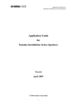
Rear Panel
y
u
!2
i
o
!0
!1
y Ground screw
The AC power cord is a 3-wire type. If the AC outlet used is earthed (grounded), this device will be properly earthed as well.
Also, grounding the screw sometimes reduces hum and interference noise.
u [AC IN] connector
Connect to the AC mains using the supplied AC power cable.
First connect the power cord to the ACD1, then insert the power cord plug into an AC outlet.
i [NETWORK] connector
This is a 100Base-TX/10Base-T Ethernet connector for connection to a computer or other device in the network.
NOTE
• Use a UTP cable or STP cable for connection to the [NETWORK] connector. (Use an STP cable in countries where FCC
regulations apply.) Since the ACD1 supports Auto MDI/MDI-X, it will automatically detect whether the connected cable is
of the straight type or crossover type, and will configure itself to create the appropriate connection. Therefore, you can
use either a straight or crossover cable.
• The maximum length of a cable between a network switch and the ACD1 is 100 meters. Due to the quality of cables and
network switch performance, however, proper operation at the maximum length cannot be guaranteed in some cases.
o [GPI] connector
This Euroblock connector provides access to the unit’s GPI (General Purpose Interface) interface for transfer of control signals to and from external equipment. The ACD1 provides 4-port input and 4-port output. The +V terminals have an output
voltage of 5 volts. The IN terminals detect voltage changes from 0V to 5V. The OUT terminals are open-collector outputs,
and change between Open and Close. For details on connections and usage, refer to “Connector wiring” (page 18). For
details on calibrating the [GPI IN] connectors, refer to “Utility” (page 13).
!0 [FAULT OUTPUT] connectors
This is a Euroblock connector that can inform an external device when an abnormality occurs with the ACD1’s CPU, or
when there is an event for which Fault Output has been specified in the Alert Setup dialog box of Amp Editor. For details on
connections and usage, refer to “Connector wiring” (page 18).
!1 [DATA PORT] connector
This is an RJ-45 connector that can be connected to a maximum of 32 PC-N/Tn series units so that they can be monitored/
controlled from the ACD1. You can use CAT5 or better UTP straight cables to make daisy-chain connections for a maximum of 500 meters.
The Amp ID of amplifiers connected to this connector must be set to non-overlapping numbers in the range of 0 to 31.
NOTE
• Use a UTP cable in which all eight pins are connected.
!2 [MONITOR/REMOTE] connector
These are D-Sub 15-pin connectors that allow up to eight XP/XH/XM series units to be connected so that they can be monitored/controlled from the ACD1. You can use three-row D-Sub 15-pin straight cable to make a connection for a maximum
of 50 meters.
Amplifiers connected to these connectors will be assigned an Amp ID between 32 and 39 according to the connector to
which they are connected.
6
ACD1 Reference Manual
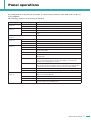
Panel operations
By pressing buttons on the panel you can monitor or control various parameters of the ACD1 itself or of the connected amplifiers.
The following parameters can be monitored/controlled.
Category
Sub category
Operation performed
1. Scene
(page 10)
Recall
Recalls a scene on the specified amplifier.
Store
Saves a scene for the specified amplifier.
2. Amp Control
(page 11)
On/Standby
Switches the power of the specified amplifier between On and Standby.
Mute
Mutes or unmutes the channel of the specified amplifier.
Attenuation
Adjusts the channel attenuator value of the specified amplifier. (PC-N/Tn series
only)
3. Output Monitor
(page 12)
4. Device Setup
(page 12)
5. Utility
(page 13)
6. Network Setup
(page 16)
Displays the output level of the specified amplifier.
Device ID
Specifies the ACD1’s Device ID address.
Device Label
Displays the name of the ACD1 assigned by Amp Editor.
Identify
Blinks the “Identify” icon of the corresponding ACD1 in Amp Editor.
Battery
Displays the state of the ACD1’s internal backup battery.
Firmware Ver.
Displays the ACD1’s firmware version.
LCD Backlight
Selects whether the ACD1’s LCD backlight will be always lit (ON) or lit only during
operation (Auto OFF).
Panel Operation
Restricts panel operations of the ACD1.
Scene Recall
Specifies whether scene recall from the ACD1’s panel is enabled (Enable) or disabled (Disable).
EMG Scene Setup
Specifies the scene number that will be recalled when the EMG (Emergency) signal is received from an external controller. If this is OFF, a scene will not be
recalled even if an EMG signal is received.
Last Mem. Resume
Specifies whether the ACD1 will start up with the settings that were in effect when
the power was last turned off (ON) or whether it will start up by recalling the amp’s
scene number that was in effect when the power was last turned off (OFF).
Clock
Sets the date and time of the ACD1’s internal clock.
GPI Calibration
Calibrates the [GPI IN] connector input voltage.
IP Address Mode
Selects whether the ACD1’s IP address will be set automatically from Amp Editor
(Auto) or set manually (Manual).
IP Address
Specifies the ACD1’s IP address.
MAC Address
Displays the ACD1’s MAC address.
IP Ctrl Port #
Specifies the port number used when controlling the ACD1 via Ethernet from an
external controller such as AMX/Crestron.
ACD1 Reference Manual
7
Panel operations
The main roles of each button are as follows.
Button
Role
[NEXT]
Moves to the next screen or parameter.
[BACK]
Moves to the previous screen or parameter.
[▲INC/YES]
Increments the value of a parameter (INC) or responds YES in response to a confirmation message.
[▼DEC/NO]
Decrements the value of a parameter (DEC) or responds NO in response to a confirmation message.
Press the [▲INC/YES] button
Press
Increments the value of a parameter.
Press and hold
Continues to increment the value of a parameter while you hold down
the button.
While holding, press the
[▼DEC/NO] button
Increments the value faster than when you hold down the [▲INC/
YES] button.
Press
Decrements the value of a parameter.
Press and hold
Continues to decrement the value of a parameter while you hold
down the button.
While holding, press the
[▲INC/YES] button
Decrements the value faster than when you hold down the [▼DEC/
NO] button.
Press the [▼DEC/NO] button
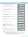
Basic operation
As an example, we’ll explain how to store the scene of an amplifier connected to the ACD1.
The basic operation is the same for all parameters.
1. From the HOME screen, press the [NEXT] button and then use
the [▲INC/YES] / [▼DEC/NO] buttons to select the [Scene] category.
NOTE
• If the screen shows “Locked,” the User Lock setting is set to
“Panel.” Enter the password to temporarily defeat User Lock. If no
password has been specified, refer to “User Lock” (page 14).
1
å.Scene
Recall
2. Press the [NEXT] button to move to the “Scene” sub-category.
1.Scene
Recall
å
3. Use the [▲INC/YES]/[▼DEC/NO] buttons to select “Store.”
4. Press the [NEXT] button to move to “Amp ID.”
8
ACD1 Reference Manual
1.Scene
Store
å
Amp ID:
01
å
00 Initial Data
Panel operations
5. Use the [▲INC/YES] / [▼DEC/NO] buttons to select the ID of
the amplifier for which you want to store settings.
6. Press the [NEXT] button to move to the scene number.
7. Use the [▲INC/YES] / [▼DEC/NO] buttons to select the scene
number that you want to store.
8. Press the [NEXT] button to move to
.
9. Press the [▲INC/YES] button to move to the screen where you
can specify the scene name.
10. Use the [▲INC/YES] / [▼DEC/NO] buttons to edit the first
character of the scene name.
11. Press the [NEXT] button to move to the next character of the
scene name.
12. Repeat steps 10 and 11 to edit the scene name.
13. Press the [NEXT] button to move to
NOTE
•
.
indication is not shown for display-only parameters, or for
parameters that reflect changes in realtime.
14. Press the [▲INC/YES] button to move to the confirmation
screen.
15. Press the [▲INC/YES] button to execute the Store operation.
Do not turn off the power while the “Do not turn off!” indication is
shown.
If you press the [▼DEC/NO] button, you will return to step 13 without
storing.
NOTE
Amp ID:
02
å
00 Initial Data
Amp ID:
02
00
Initial
Data
å
Amp ID:
03:NO
SCENE
å
02
Amp ID:
03:NO SCENE
02
å
03:Initial
Data
å
03:1nitial
Data
å
03:1nitial
Data
å
03:1stStage 01å
03:1stStage 01 å
03:1stStage 01
Are You Sure?
File writing
Do not turn off!
• If the display indicates “Parameter Locked!”, Panel Operation is set to “View Only.” To temporarily defeat the panel lock,
hold down both the [▲INC/YES] / [▼DEC/NO] buttons for at least three seconds. To disable the panel lock, first defeat it
temporarily, and then turn the Panel Operation setting Normal (page 14).
• If the screen indicates “Scene Store: XX Overwrite?”, scene data has already been stored in the selected scene. If you
want to overwrite the existing data, press the [▲INC/YES] button. If you want to store the settings to a different scene
number without overwriting, return to step 7, and re-select the scene number for storing.
ACD1 Reference Manual
9
Panel operations
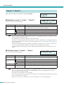
Scene (“1. Scene”)
Here’s how to recall or store scenes for a specified amplifier.
1.Scene
å
Recall
■ Recalling a scene (“1. Scene” ➝ “Recall”)
Amp ID:
01
å
01:Scene Name
Recalls a scene for the specified amplifier.
Parameter
Amp ID
Range
00–39, ALL
Attributes of the
scene
Explanation
Selects the ID of the amplifier for which to recall a scene. If you select “ALL,” the correspondingly-numbered scene will be recalled for all amplifiers.
Preset scene
A user scene that is protected
A user scene that is not protected
Scene No.
NOTE
00–49
Selects the scene number to be recalled.
• If you select “ALL” as the Amp ID, the scene name will not be displayed.
• If you select “ALL” as the Amp ID, amplifiers for which there is no correspondingly-numbered scene data will not recall a
scene; they will retain their previous state.
• Scene number 00 is for returning the amplifiers to their default settings.
• If characters not supported by the ACD1 were used for the scene name in Amp Editor, the corresponding locations will
be shown as “~.” For details on the characters supported by the ACD1, refer to “List of supported characters” (page 21) at
the end of this manual.
• Scene names that can be displayed by the ACD1 are a maximum of 12 characters. If a scene name of 13 characters or
longer is specified in Amp Editor, the ACD1 will not display the thirteenth and subsequent character.
• If you edit a parameter after recalling a scene, the E symbol (edit symbol) will be shown in screens that show the scene
number.
■ Storing a scene (“1. Scene” ➝ “Store”)
Amp ID:
01
å
01:Scene Name
Stores a scene for the specified amplifier.
Parameter
Amp ID
Range
00–39, ALL
Attributes of the
scene
Explanation
Selects the ID of the amplifier for which to store a scene. If you select “ALL,” the current scene will be stored to the selected scene number of all amplifiers.
Preset scene
A user scene that is protected
A user scene that is not protected
Scene No.
01–49
Selects the scene number to be stored.
Scene name
See character list at
the end of this manual
Enter the name of the scene to store. A maximum of 12 characters can be entered.
NOTE
• If the screen indicates “(scene number):(scene name) Overwrite?”, scene data has already been stored in the selected
scene. If you want to overwrite the existing data, press the [▲INC/YES] button. If you want to store the settings to a different scene number without overwriting, press the [▼DEC/NO] button, then press the [BACK] button several times,
and re-select the scene number for storing.
• Scene data is saved in the ACD1, not in each amplifier.
• Stored scene data is valid only for the identical model of amplifier. Scene data will be ignored if a different model of amplifier is connected with the same Amp ID.
• When you store a scene, the E symbol shown in screens that indicate the scene number will disappear.
10
ACD1 Reference Manual
Panel operations
Controlling an amplifier (“2. Amp Control”)
These settings allow you to control an amplifier connected to the
ACD1.
2.Amp Control
å
Standby
■ Power on/standby (“2. Amp Control” ➝ “Standby”)
Switches the power of the specified amplifier between On and Standby.
Parameter
Range
Amp ID:
01
å
Standby
Explanation
Amp ID
00–39, ALL
Selects the ID of the amplifier whose power will be switched. If you select “ALL,” the
power of all amplifiers will be switched to the specified state.
Power supply status
Standby/On
Selects the status of the power supply.
NOTE
• If you select “ALL” as the [Amp ID], the power supply status may indicate “Some Standby.” This means that the power is
On for some amplifiers, and Standby for others.
■ Mute (“2. Amp Control” ➝ “Mute”)
Mutes or unmutes the channel of the specified amplifier.
Parameter
Range
Amp Ch:
A
Muted
å
Explanation
Amp ID
00–39, ALL
Selects the ID of the amp whose channel is to be muted. If you select “ALL,” the mute
status for all channels of all amplifiers will be switched.
Amp Ch
A–H, ALL
Selects the channel whose mute status is to be switched. The range of channels that
can be selected will depend on the amplifier you select. If you select “ALL,” the mute
status for all channels of the selected amplifier will be switched.
Mute status
Muted/Unmuted
Selects the mute status.
NOTE
• If you select “ALL” as the [Amp ID], the mute status may indicate “Some Muted.” This indicates that there are both muted
and unmuted channels.
■ Attenuator value adjustment (“2. Amp Control” ➝ “Attenuation”)
Adjusts the channel attenuator value of the specified amplifier. The attenuator
value can be adjusted only for amplifiers (as of September 2009: the PC-N/
Tn series) connected to the [DATA PORT] connector.
Parameter
Range
Amp Ch:
A
-48.0dB
å
Explanation
Amp ID
00–31
Selects the ID of the amp for which the attenuator value of a channel is to be adjusted.
Amp Ch
A–H
Selects the channel whose attenuator value is to be adjusted. The range of channels
that can be selected will depend on the amplifier you select.
Attenuator value
0 dB– -78 dB, -∞
Selects the attenuator value.
The selectable range is 0 dB through -44 dB in 1 dB steps, -44 dB through -78 dB
in 2 dB steps, with -78 dB followed by -∞.
ACD1 Reference Manual
11
Panel operations
Amplifier output monitor (“3. Output Monitor”)
This indicates the output level of the amp connected to the ACD1.
3.Output Monitor
å
■ Amplifier output (“3. Output Monitor”)
Displays the output level for each channel of the specified amplifier.
Parameter
Range
Amp ID:
A~B~
01
å
Explanation
Amp ID
00–39
Selects the ID of the amp whose output level you want to view.
Level
0
Nothing will appear in the meter if the level is below 0 dBu.
1
0–6 dBu
2
6–16 dBu
3
16–22 dBu
4
22–28 dBu
5
28–34 dBu
6
34–41 dBu
7
41 dBu–
Device setup (“4. Device Setup”)
Here you can make settings to identify the ACD1 connected to the
network and the amplifiers connected to the ACD1.
4.Device Setup
å
Device ID
■ Device ID setting (“4. Device Setup” ➝ “Device ID”)
Specifies the ACD1’s Device ID. Set the Device ID so that it does not conflict with another ACD1 etc. connected to the network.
Device ID
001
å
Parameter
Device ID
NOTE
Range
000–255
Explanation
Selects the ACD1’s Device ID.
• If you press and hold down this button for three seconds or longer while the HOME screen is displayed, the screen will
appear.
■ View ACD1 name (“4. Device Setup” ➝ “Device Label”)
Displays the name of the ACD1 assigned by Amp Editor.
NOTE
• This shows up to 14 alphanumeric characters. The fifteenth and
following characters will not be shown.
• Characters not appearing in the character list at the end of this
manual are displayed as “~.”
12
ACD1 Reference Manual
Device Label
[Rack L-ACD1
]
Panel operations
■ Identify (“4. Device Setup” ➝ “Identify”)
Blinks the “Identify” icon of the corresponding ACD1 in Amp Editor.
Identify
ON
å
Parameter
Identify
Range
ON/OFF
Explanation
If this is [ON], the “Identify” icon of the corresponding ACD1 in Amp Editor will blink.
Turning this [OFF] will defeat the blinking.
Utility (“5. Utility”)
Here you can make overall settings for the ACD1 and view various
types of information.
5.Utility
å
Battery
■ Backup battery check (“5. Utility” ➝ “Battery”)
Displays the state of the ACD1’s internal backup battery.
Battery
OK
Parameter
Battery
CAUTION
Range
Explanation
OK
Satisfactory.
Low Battery
The battery is running low.
No Battery
A battery is not installed, or has malfunctioned. The backup data has been lost.
• As the battery runs down, the display will successively indicate “Low Battery,” “Critical Battery” (only when the power is
turned on), or “No Battery.” In this case, immediately save the data to a computer or other external device, and then contact your Yamaha dealer listed at the end of the ACD1 owner’s manual to have the backup battery replaced.
■ Version indication (“5. Utility” ➝ “Firmware Ver.”)
Displays the ACD1’s firmware version.
NOTE
• You can use Amp Editor to update the ACD1’s firmware. For
details, refer to the Amp Editor owner’s manual.
You can download the latest firmware from the download page of
the following Yamaha website.
Firmware Ver.
V1.10
http://www.yamahaproaudio.com/
ACD1 Reference Manual
13
Panel operations
■ LCD backlight (“5. Utility” ➝ “LCD Backlight”)
This specifies the lit status of the ACD1’s LCD backlight.
Parameter
LCD Backlight
Range
LCD Backlight
ON
å
Explanation
ON
The backlight will stay lit.
Auto OFF
The backlight will go dark automatically.
It will light when you perform a panel operation, and will automatically go dark ten seconds afterward.
■ Restricting panel operations (“5. Utility” ➝ “Panel Operation”)
Here you can turns panel operation lock on/off. By locking panel operations
you can prevent unintended operation.
Parameter
Panel Operation
NOTE
Range
Panel Operation
Normal
å
Explanation
Normal
Panel lock (locking of all panel operations) will be turned off.
View Only
It will be impossible to edit parameters via the panel. It will be possible to switch the
screen display.
Full Lock
All panel operations other than temporarily defeating the panel lock will be disabled.
• You can hold down both the [▲INC/YES] and [▼DEC/NO] buttons for approximately three seconds until the display indicates “Unlock panel: Are you sure?”, then press the [▲INC/YES] button to temporarily defeat Panel Lock until the ACD1
is powered-off.
• You can also clear it by turning the Front Panel Operation setting Normal from Amp Editor.
■ Enabling scene recall operations from the panel
(“5. Utility” ➝ “Scene Recall”)
This specifies whether scene recall by operating the ACD1’s front panel will
be allowed or disabled.
Parameter
Explanation
Amp ID
00–39, ALL
Specifies the ID of the amp for which scene recall will be enabled. If you select “ALL,”
the scene recall enable status of all amplifiers will be switched to the specified state.
Scene Recall
Enable
Enabled.
Disable
Disabled. Scene recall can be executed from Amp Editor.
NOTE
14
Range
Amp ID:
01
å
Enable
• If you select “ALL” as the [Amp ID], the Scene Recall area may indicate “Some ON.” This means that scene recall is
enabled for some amplifiers but disabled for other amplifiers.
ACD1 Reference Manual
Panel operations
■ Enabling scene recall operations via EMG commands
(“5. Utility” ➝ “EMG Scene Setup”)
Specifies whether the EMG scene will be recalled when the EMG (Emergency) signal is received.
The following three types of EMG signal can be received.
Amp ID:
01
å
OFF
• EMG command sent from AMX/Crestron
• Input signal to the GPI IN assigned to the Emergency scene
• EMG command sent from a different ACD1 unit
Parameter
Range
Explanation
Amp ID
00–39, ALL
Specifies the ID of the amp for which EMG scene recall will be enabled. If you select
“ALL,” the EMG scene recall enable status of all amplifiers will be switched to the
specified state.
EMG Scene Setup
00–49
Recalls the specified scene.
OFF
A scene will not be recalled even if an EMG signal is received.
NOTE
• If you select “ALL” as the [Amp ID], the EMG Scene Setup area may indicate “Some ON.” This means that EMG scene
recall is enabled for some amplifiers but disabled for other amplifiers.
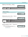
■ LAST MEMORY RESUME setting (“5. Utility” ➝ “Last Mem. Resume”)
This specifies whether the unit will start up in the state in which it was powered-off, or recall the scene of the scene number that was selected at poweroff.
Parameter
Last Mem. Resume
Range
Last Mem.Resume
ON
å
Explanation
ON
The unit will start up in the state in which it was powered-off.
OFF
At start-up, the unit will recall the scene that was last recalled or stored before the
power was turned off.
■ Clock setting (“5. Utility” ➝ “Clock”)
Sets the date and time of the ACD1’s internal clock.
Parameter
Range
Clock
DST
01-Oct-09
16:43
å
Explanation
Date
01–31
Sets the date.
Month
Jan–Dec
Sets the month.
Year
00–99
Sets the year. The last two digits of the Western calendar year can be specified.
Hour
00–23
Sets the hour.
Minute
00–59
Sets the minute.
NOTE
• The seconds will be set to 00 when you finalize the time.
• If Daylight Saving Time is enabled in Amp Editor, this will indicate “DST.”
ACD1 Reference Manual
15
Panel operations
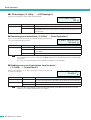
■ GPI IN calibration (“5. Utility” ➝ “GPI Calibration”)
Calibrates the detected range of the [GPI IN] connector input voltage.
Parameter
Range
Port No.:
3
Min:3.4V->4.2V
å
Explanation
Port No.
1–4
Selects the port of the [GPI IN] connector that will be calibrated.
Minimum/maximum
value setting
Min/Max
Selects whether you will be setting the minimum (Min) or maximum (Max) value for
the input voltage.
Voltage value
--
Indicates the input voltage.
At the left of the “–>” symbol is shown the specified voltage (maximum/minimum
value), and at the right is shown the current input voltage. When you confirm the setting, the current input voltage will be assigned as the maximum/minimum value.
Network settings (“6. Network Setup”)
Here you can make network settings for the ACD1.
6
å.Network Setup
IP Address Mode
■ IP Address Mode setting (“6. Network Setup” ➝ “IP Address Mode”)
This specifies whether the ACD1’s IP address will be set automatically by
Amp Editor’s Network Setup or a DHCP server, or manually.
Parameter
IP Address Mode
NOTE
Range
IP Address Mode
DHCP
å
Explanation
DHCP
The address will be set automatically. If you power-off in this mode, the IP address
setting will be cleared.
Manual
The address will be set manually. In this mode, the IP address setting will be saved
even if you power-off.
• If you’re using a DHCP server, start up the DHCP server before the ACD1.
• For details on this mode, refer to the Amp Editor owner’s manual.
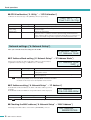
■ IP Address setting (“6. Network Setup” ➝ “IP Address”)
If the IP Address Mode is Manual, the ACD1’s IP address will be specified
manually.
If the IP Address Mode is DHCP, the assigned IP address will be displayed.
Parameter
IP Address
NOTE
Range
001.000.000.001–223.255.255.254
IP Address
192.168.000.002
å
Explanation
Specifies the ACD1’s IP address.
• If the IP Address mode is DHCP, the manually assigned IP address will be ignored.
■ Checking the MAC address (“6. Network Setup” ➝ “MAC Address”)
This displays the MAC address of the ACD1’s [NETWORK] connector.
16
ACD1 Reference Manual
MAC Address
00A0DE251500
Panel operations
■ Port settings for an external controller
(“6. Network Setup” ➝ “IP Ctrl Port #”)
Here you can specify the port number that will be used to control the ACD1
from an external device such as an AMX or Crestron unit.
Parameter
Port No.
Range
49153–50049
IP Ctrl Port #
49153
å
Port number (hexadecimal)
Specifies the ACD1’s port number. Change the port number if there are other devices
(other than the ACD1) that use the same port number.
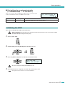
Initializing the ACD1
Here’s how to initialize the ACD1’s internal memory.
CAUTION
• When you initialize the internal memory, the content that had been saved in memory (scenes for each amp, and ACD1
settings) will be lost.
Use caution when performing the following steps.
1. Power-off the ACD1.
2. While holding down the [BACK] button, turn the power on.
3. Press the [▲INC/YES] button to initialize the internal memory.
Initialize
Are you sure?
• Do not turn off the power during the initialization process.
CAUTION
4. When initialization is completed, the ACD1 will automatically restart.
NOTE
• The log data is preserved even if you execute initialization.
ACD1 Reference Manual
17
Connector wiring
This section explains how to wire the [GPI] and [FAULT OUTPUT] connectors located on the ACD1’s rear panel.
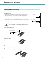
Euroblock plug connection
Be sure to use the supplied Euroblock connector. If you lose the connector, contact your Yamaha dealer.
● Cable preparation
• To prepare the cable for attachment to a Euroblock connector, strip the wire as
shown in the illustration, and use stranded wire to make connections. With a
Euroblock connection, the stranded wire may be prone to breakage because of
metal fatigue due to the weight of the cable or due to vibration. When rack-mounting your equipment, use a lacing bar when possible to bundle and fasten the cables.
• If cables will be frequently connected and disconnected, as in the case of a portable
installation, we recommend that you use ferrules with insulation sleeves. Use a ferrule whose conductor portion has an external diameter of 1.3 mm or less, and a
length of approximately 5 mm (such as the AI0,5-6WH made by the Phoenix Contact corporation).
approx.
5 mm
1.3 mm
or less
approx.
5 mm
• If you use stranded wire, do not tin (plate with solder) the exposed end.
CAUTION
1. Loosen the terminal screws.
NOTE
• Use a slotted screwdriver with a blade approximately 2 mm wide.
Slotted screwdriver
2 mm
Loosen
Euroblock plug
Terminal screw
2. Insert the cables.
3. Securely tighten the terminal screws.
Pull the cables (not too strongly) to confirm that they are securely connected.
4. Connect the Euroblock plug to the ACD1’s [GPI] connector / [FAULT OUTPUT] connector.
18
ACD1 Reference Manual
Connector wiring
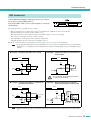
GPI connector
Connect GPI (General Purpose Interface) devices (e.g., controllers) to the rear panel [GPI] connector.
You can use GPI to send or receive control signals to or from an
external device.
GND
OUT
GND
IN
Voltage
The ACD1 provides 4-port input and 4-port output.
•
•
•
•
•
•
The +V terminals have an output voltage of 5 V. A maximum total of 100 mA of current can be drawn.
The IN terminals detect voltage changes from 0 V to 5 V.
The OUT terminals are open-collector outputs. A maximum voltage of +12 V can be applied.
For each port, a maximum of 75 mA of current can flow.
Use Amp Editor to make settings such as parameter assignments.
A Euroblock plug is used for connection to the [GPI] connector.
Euroblock connection methods are described in “Euroblock plug connection” (page 18) in this manual.
NOTE
• By specifying the input/output channels in Amp Editor, you can recall scenes or edit parameters from a connected external GPI device, or send signals to an external GPI device. For details on making settings, refer to the “Amp Editor owner’s
manual.”
● Example : Controlling the ACD1 from a switch
● Example : Lighting the LED of an external device
from the ACD1
ACD1
ACD1
+5V
+5V
+V
CPU
+V
10
IN
A/D
OUT
CPU
100k
Max. 75 mA
• Do not allow the current flowing from the OUT
connector to exceed 75 mA.
CAUTION
● Example : Controlling the ACD1 via a 10k ohm linear taper potentiometer
● Example : Switching the relay of an external
device from the ACD1 to light an LED
ACD1
ACD1
+5V
+5V
+V
+
+V
CPU
IN
A/D
GND
100k
Continuously
variable
volume
10
CPU
OUT
–
Max. 75 mA
NOTE
• To adjust (calibrate) the range over which the input voltage to the [GPI] connector is detected, refer to “5. Utility” (page
13).
ACD1 Reference Manual
19
Connector wiring
FAULT OUTPUT connector
You can connect a lamp etc. to the rear panel [FAULT OUTPUT] connector to
indicate that an abnormality has occurred.
The [FAULT OUTPUT] connector consists of NO (Normally Open), C (Common), and
NC (Normally Closed). The [FAULT OUTPUT] connector is a relay circuit, and operates as follows.
Normal state
Abnormal state
Powered-off
NO
Open
Closed
Closed
NC
Closed
Open
Open
The relay contacts used in the [FAULT OUTPUT] connector are rated for a load of 1A, DC 30V. Do not apply a load that
exceeds this rating.
Use Amp Editor to make settings for the [FAULT OUTPUT] connector.
Euroblock plugs are used for the [FAULT OUTPUT] connector. Euroblock connection methods are described in “Euroblock
plug connection” (page 18) in this manual.
• In Amp Editor’s [Device Setup] menu ➝ [Alert Setup], you can set Type to Fault so that a fault can be indicated by a connected lamp, etc. For details on making settings, refer to the “Amp Editor owner’s manual.”
NOTE
● Example : Using an LED to indicate normal/fault status of the ACD1
Normal state
Powered-off / Abnormal state
ACD1
ACD1
NC
Lit
C
NC
Unlit
C
NO
NO
Unlit
Lit
• The relay contacts are rated for a resistive load of 1A, DC 30V. Do not apply a load that exceeds this rating.
CAUTION
20
ACD1 Reference Manual
Appendix
Display messages
Messages that may appear in the ACD1’s display and the appropriate responses are listed below. For more about
alert messages, refer to the Amp Editor owner’s manual.
Message
Response
Panel locked!
To prevent unintended operation, panel operations have been locked by the Panel Operation setting.
To temporarily defeat Panel Operation, hold down both the [▲INC/YES] / [▼DEC/NO] buttons for at
least three seconds. To turn Panel Lock off, first defeat it temporarily, and then change the “5.Utility” ➝
“Panel Operation” setting to Normal.
Parameter
locked!
To prevent unintended operation, parameter editing has been locked by the Panel Operation setting.
To temporarily defeat Panel Operation, hold down both the [▲INC/YES] / [▼DEC/NO] buttons for at
least three seconds. To turn Panel Lock off, first defeat it temporarily, and then change the “5.Utility” ➝
“Panel Operation” setting to Normal.
Unlock panel:
Are you sure ?
This is displayed when you temporarily defeat User Lock.
To defeat the setting, press the [▲INC/YES] button.
Scene storing
Do not turn off!
A scene is being stored. Never turn off the power while this message is shown.
Cannot edit
while online!
Settings cannot be edited, because the unit is online with Amp Editor.
Scene protected!
You cannot store to a protected scene.
File writing
Do not turn off!
A file is being written to internal memory. Never turn off the power while this message is shown.
Initializing
Do not turn off!
Internal memory is being initialized. Never turn off the power while this message is shown.
Updating f/ware
Do not turn off!
The firmware is being updated. Never turn off the power while this message is shown.
Synchronizing
Do not turn off!
Now synchronizing with Amp Editor. Never turn off the power while this message is shown.
System error
Initialize the memory. If this does not solve the problem, contact your Yamaha dealer.
Saving failed
Flash ROM error
It is likely that the device has malfunctioned; please contact your Yamaha dealer.
Network HW error
Illegal MAC adr
Scene recall err
Current scn lost
The backup battery may have run down. Contact your Yamaha dealer.
No battery
When you turn off the power, the current settings will be lost, and will return to the default values.
Immediately stop using the unit, and contact your Yamaha dealer.
Critical battery
Low battery
If you continue operation, settings may be lost and return to the default values. Contact your Yamaha
dealer as soon as possible.
Duplicate IP adr
Re-specify the IP addresses so that they do not conflict.
Amp comm error
Make sure that each of the connected amplifiers has a unique ID. Alternatively, a cable may be shortcircuited or noise may be affecting the connection.
List of supported characters
The ACD1 allows the following single-byte characters to be displayed and input.
Uppercase alphabet
A B C D E F G H I J K L M N O P Q R S T U V W X Y Z
Lowercase alphabet
a b c d e f g h i j k l m n o p q r s t u v w x y z
Numerals
0 1 2 3 4 5 6 7 8 9
Symbols
! " # $ % & ' ( ) * + , - . / : ; < = > ? @ [ \ ] ^ _ ` {
} (Space)
ACD1 Reference Manual
21
Appendix
Troubleshooting
Symptom
Possible causes
Response
All scene data saved in
the ACD1 has disappeared
The power was turned off while the
ACD1’s data was being saved
Once again synchronize the unit with Amp Editor to transmit
the settings from Amp Editor.
The internal battery has run down
Go to “5. Utility” ➝ “Battery” to check the battery status. If the
indication is “Low Battery” or “No Battery,” contact your
Yamaha dealer listed at the end of the ACD1 owner’s manual
to have the battery replaced.
Cannot edit parameters
Panel Lock is enabled
Change the “5. Utility” ➝ “Panel Operation” setting to Normal,
or use Amp Editor to defeat Panel Operation.
You are attempting to edit a parameter of
an amplifier that is not connected
Connect the amplifier whose settings you want to change.
The corresponding amplifier is not powered-on
Power-on the amplifier whose settings you want to change.
The power cable is not connected properly
Connect the power cable properly.
The POWER switch is not turned on
Turn the POWER switch on.
The backlight setting is “Auto OFF”
If you want the LCD backlight to stay lit, turn the “5. Utility” ➝
“LCD Backlight” setting “ON.”
Can’t synchronize with
Amp Editor
A cable is disconnected or broken
Check whether a cable might be disconnected or broken.
Amplifier does not operate as specified
The amplifier was powered-on before the
ACD1
Power-on the equipment so that the ACD1 starts-up before
the amplifiers connected to the ACD1.
Can’t monitor/control an
amplifier
A cable is disconnected or broken
Check whether a cable might be disconnected or broken.
A cable exceeds the allowable length
Make sure that the cable connected to the [MONITOR/
REMOTE] connector is no longer than 50 meters.
Make sure that the cable connected to the [DATA PORT] connector extends no longer than a total of 500 meters to its last
point.
Make sure that each individual cable between your computer
and the ACD1 is no longer than 100 meters.
In the middle of a daisy-chain there is an
amplifier whose T-switch is ON
Turn off the T-switch for all amplifiers other than the last amplifier.
Power will not turn on,
display will not light
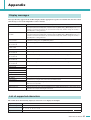
Specifications
Scene Memory
Number of amplifiers
that can be connected
22
50 scenes per amplifier
Via the DATA PORT connector
Up to 32 units
Via the MONITOR/REMOTE
connector
Up to 8 units
Display
16 characters × 2 lines backlit LCD
Power Requirements
100 V, 50 Hz/60 Hz
Power Consumption
15 W
Dimensions (W × H × D)
480 × 44 × 362 mm
Weight
4.0 kg
Operating temperature range
0 °C–40 °C
Storage temperature range
-20 °C–60 °C
AC Cable Length
250 cm
Accessories
AC power cord, Euroblock plug (16P), Owner’s Manual, Rubber feet × 4
ACD1 Reference Manual
Appendix
Control I/O
Terminal
MONITOR/REMOTE *1
DATA PORT *2
GPI *3
Format
Level
—
—
RS-485
RS-485
IN
—
0–5 V
OUT
—
Open Collector
+V
—
5V
FAULT OUTPUT *4
NETWORK
—
—
IEEE 802.3
10Base-T/100Base-TX
Connector
D-SUB 15P (Female) × 8
RJ-45
Euroblock (3.5 mm pitch)
RJ-45
*1 Supported models
XP7000, XP5000, XP3500, XP2500, XP1000, XM4180, XM4080, XH200
Guaranteed cable length: 50m
*2 Supported models
T5n, T4n, T3n, PC9501N, PC6501N, PC4801N, PC3301N, PC2001N, PC9500N, PC4800N, PC3300N
*3 Inputs: 4channels, Outputs: 4channels
Outputs: Withstanding Voltage Vmax = 12V (Open)
Outputs: Sink Current Imax = 75mA/pin (Closed)
+V: Imax =100mA/2pins
*4 Input: Imax = 1A, Vmax = 30VDC
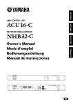
Pin Assignment
■ MONITOR/REMOTE
5
10
4
9
15
3
8
14
2
7
13
1
6
12
11
1
2
3
4
5
6
7
8
9
10
11
12
13
14
15
GND
REMOTE CONTROL
MONITOR
REMOTE CONTROL
1
2
3
4
5
6
7
8
NC
NC
NC
RxD/TxD RxD/TxD +
NC
GND
GND
MONITOR
STANDBY
MODEL ID
MUTE CH D
MUTE CH C
MUTE CH B
MUTE CH A
PROTECT STATUS CH D
PROTECT STATUS CH C
PROTECT STATUS CH B
PROTECT STATUS CH A
OUTPUT LEVEL CH D
OUTPUT LEVEL CH C
OUTPUT LEVEL CH B
OUTPUT LEVEL CH A
■ DATA PORT
1
8
ACD1 Reference Manual
23
Appendix
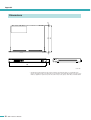
480
362
(1)
44
3
354
(5)
Dimensions
Unit : mm
* Specifications and descriptions in this owner’s manual are for information purposes only. Yamaha Corp.
reserves the right to change or modify products or specifications at any time without prior notice. Since specifications, equipment or options may not be the same in every locale, please check with your Yamaha dealer.
24
ACD1 Reference Manual
U.R.G., Pro Audio & Digital Musical Instrument Division, Yamaha Corporation
© 2009 Yamaha Corporation
911-PO-C0