1
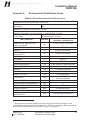
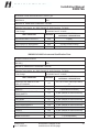
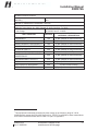
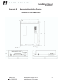
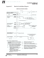
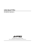
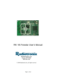
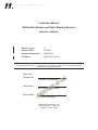
H E A D S
U P
T E C H N O L
O G I E S
Installation Manual
XM Satellite Weather and Radio Wireless Receiver
Model No. XMD076A
Revision Level:
C
Revision Date:
06/22/06
Document Control No.:
XMD076A-3
File Name:
XMD076A-3_C.doc
This document contains copyrighted material and confidential trade secret information belonging exclusively
to Heads Up Technologies, Inc. Unauthorized use, disclosure, or duplication of any of this material may
result in liability under applicable laws.
Approvals:
Prepared By:
J. Header, Engineering
Checked By:
M. Wootton, Engineering
Approved By:
D. Groos, Marketing
Heads Up Technologies, Inc.
2033 Chenault Dr., Suite 100
Carrollton, Texas 75006
H E A D S
U P
T E C H N O L
O G I E S
Installation Manual
XMD076A
Important Information
CHANGES OR MODIFICATIONS TO THIS DEVICE NOT EXPRESSLY APPROVED BY
THE MANUFACTURER COULD VOID THE USERS AUTHORITY TO OPERATE THE
EQUIPMENT.
WARNING: INFORMATION SUBJECT TO EXPORT CONTROL LAWS
This manual may contain information subject to the International Traffic in Arms Regulation
(ITAR) or the Export Administration Regulation (EAR) of 1979 which may not be exported,
released, or disclosed to foreign nationals inside or outside of the United States without first
obtaining an export license. A violator of the ITAR or EAR may be subject to a penalty of up to
10 years imprisonment and a fine of up to $1,000,000 under 22 USC 2778 of the Arms Export
Control Act of 1976 or section 2410 of the Export Administration Act of 1979. Include this notice
with any reproduced portion of this document.
PROPRIETARY NOTICE
NOTICE: FREEDOM OF INFORMATION ACT (5 USC 552) AND DISCLOSURE OF
CONFIDENTIAL INFORMATION GENERALLY (18 USC 1905).
This document and the information disclosed herein are proprietary data of Heads Up
Technologies. Neither this document nor the information contained herein shall be used,
reproduced, or disclosed to others without the written authorization of Heads Up Technologies,
except to the extent required for installation or maintenance of recipient’s equipment. This
document is being furnished in confidence by Heads Up Technologies. The information disclosed
herein falls within exemption (b) (4) of 5 USC 552 and the prohibitions of 18 USC 1905.
SOFTWARE COPYRIGHT NOTICE
COPYRIGHT, 1998, 1999, 2000, 2001, 2002, 2003, 2004, 2005, 2006
HEADS UP TECHNOLOGIES
All software resident in this equipment is protected by copyright.
We welcome your comments concerning this manual. Although every effort has been made to
keep it free from errors, some may occur. When reporting a specific problem, please describe it
briefly and include the manual number, the paragraph or figure number, and the page number.
Please submit comments regarding this manual to the following address:
Document Control Manager
Heads Up Technologies
2033 Chenault Dr., Suite 100
Carrollton, TX 75006-5097
XMD076A-3
Rev C, 06/22/06
Information is subject to the
restrictions on the title page
ii
H E A D S
U P
T E C H N O L
O G I E S
Installation Manual
XMD076A
Revision Record
Revision
Level
Description of Changes
Author
Approved
by
Release
Date
-
Initial Release
JH
DJG
9/27/05
A
Added Bluetooth antenna
specifications and professional
installation warning.
JH
DJG
11/18/05
B
Changed Satellite Antenna cable
requirements: Added Section 2.4.1
and changed Note 3 in App. B
diagram. Added pre-activation
information for XM Radio operation.
Updated XM Radio phone number.
Antenna coax cable length equation
re-formated to avoid confusion.
DJG
04/05/06
JH
06/22/06
C
XMD076A-3
Rev C, 06/22/06
JH
Information is subject to the
restrictions on the title page
iii
H E A D S
U P
T E C H N O L
O G I E S
Installation Manual
XMD076A
Table of Contents
Section
1.0
Description
Page
GENERAL INFORMATION .................................................................................................... 1
1.1 EQUIPMENT DESCRIPTION ............................................................................................................. 1
1.2 TECHNICAL SPECIFICATIONS ......................................................................................................... 3
1.2.1 Environmental Qualification Identification........................................................................... 3
2.0
INSTALLATION INSTRUCTIONS ......................................................................................... 4
2.1 UNPACKING AND INSPECTION ........................................................................................................ 4
2.2 SYSTEM IDENTIFICATION NUMBERS............................................................................................... 4
2.3 XMD076A RECEIVER INSTALLATION............................................................................................ 5
2.3.1 Installation Considerations .................................................................................................. 5
2.3.2 Mounting the XMD076A ...................................................................................................... 5
2.3.3 Electrical Interface Wiring................................................................................................... 6
2.3.4 Electrical Load Analysis ...................................................................................................... 8
2.4 XM SATELLITE ANTENNA INSTALLATION CONSIDERATIONS .......................................................... 9
2.4.1 Antenna Coaxial Cable Installation...................................................................................... 9
2.4.2 Interference from VHF and SATCOM Transmitters ............................................................ 10
2.5 WEIGHT AND BALANCE............................................................................................................... 12
3.0
SYSTEM CHECKOUT ........................................................................................................... 13
3.1 INITIAL INSTALLATION VALIDATION TEST ................................................................................... 13
3.2 SYSTEM TEST ............................................................................................................................. 13
3.2.1 Service Activation .............................................................................................................. 13
3.2.2 Power System and Initial Test ............................................................................................ 14
3.3 GROUND EMI CHECK ................................................................................................................. 17
4.0
FACTORY SERVICE POLICIES .......................................................................................... 18
4.1 TECHNICAL SUPPORT .................................................................................................................. 18
4.2 GENERAL SERVICE PROCEDURES ................................................................................................. 18
APPENDIX A ENVIRONMENTAL QUALIFICATION FORMS .................................................... 19
APPENDIX B MECHANICAL INSTALLATION DIAGRAM ......................................................... 22
APPENDIX C ELECTRICAL INSTALLATION DIAGRAM........................................................... 23
XMD076A-3
Rev C, 06/22/06
Information is subject to the
restrictions on the title page
iv
H E A D S
U P
T E C H N O L
O G I E S
Installation Manual
XMD076A
1.0
General Information
This manual provides product description and installation reference information for the
Heads Up Technologies XMD076A XM Satellite Weather and Radio Wireless Receiver.
This receiver is for use with specific Avidyne XM WX software equipped Multi-Function
Displays (MFD’s) only. Please refer to the Avidyne MFD documentation for software
configuration requirements and operating instructions.
1.1
Equipment Description
The XMD076A is a dual function device serving as a broadcast datalink for the cockpit
MFD and provides entertainment audio. The XMD076A receives streaming weather and
audio data transmitted from XM Satellite Radio, Inc. The XMD076A is a remote mounted
“sensor” which requires 14-28V DC power, ground, a connection to an external antenna
and audio interface. It interfaces to the MFD over a single receive/transmit pair of RS232
signals. Audio interfaces include headphones or connection to aircraft audio panels.
A complete system would consist of the following components, sold separately:
•
Heads Up Technologies XMD076A (illustrated here)
XMD076A-3
Rev C, 06/22/06
Information is subject to the
restrictions on the title page
1
H E A D S
U P
T E C H N O L
O G I E S
Installation Manual
XMD076A
•
XMC050 XM Radio
Wireless Remote
Controller (illustrated here)
•
Many options of XM Satellite Radio certified antennas are available and
manufactured by Comant Industries. Single and combination function antennas
are available. For a complete listing of available antennas, contact the Heads Up
Technologies sales department at:
•
Email:
[email protected] Web:
www.heads-up.com
Voice:
972-980-4890
972-980-4843
Fax:
Optional system installation kit including necessary connectors and installation
documentation
XMD076A-3
Rev C, 06/22/06
Information is subject to the
restrictions on the title page
2
H E A D S
U P
T E C H N O L
O G I E S
Installation Manual
XMD076A
1.2
Technical Specifications
STANDARD FEATURES
Display
None. User interface through XMC050 controller
WX Interface
RS232, 115.2Kbaud, No parity, 8-bit, 1 stop bit
Audio Interface
(Typical)
Stereo 600-ohm balanced transformer, 0dBV nominal
level, <-50dBV (when muted) to +12dBV (Full volume)
Wireless Link
Bluetooth Class 2 (low power, 25 Ft. LOS Range)
FCC ID # TGVXMSC63. This device complies with Part 15 of
the FCC rules subject to the following two conditions:
1. This device may not cause harmful interference.
2. This device must accept all interference received, including
interference that may cause undesired operation.
Wireless Antenna
GigaAnt Titanis 2.4GHz, P/N 2010B4844-01 Gain: 4.4dBi
PHYSICAL CHARACTERISTICS
Receiver Weight
1.7 lbs.
Receiver
Dimensions H, W, L
1.8 X 6.5 X 7.8 Inches (Refer to Appendix B for more
detail)
Antenna Weight
Refer to specific antenna installation drawing
OPERATING LIMITS
Power Input Voltage
11-32VDC, negative ground
0.63A at 11.0VDC minimum power input voltage
Steady State
Current
0.48A at 13.8VDC power input voltage
0.26A at 27.6VDC power input voltage
1.2.1 Environmental Qualification Identification
IAW RTCA DO-160E Appendix A and Heads Up Technologies document XMD076A-34,
the following environmental category identification applies to the XMD076A:
“DO-160E Env. Cat.,[(F2)X]BBB[SBM]HXXXFXZ[(B)(Z)]AZ[ZC][RR]M[Z2XXX]XXAX”
For a description of the equipment categories, refer to Environmental Qualification
Forms included in Appendix A.
XMD076A-3
Rev C, 06/22/06
Information is subject to the
restrictions on the title page
3
H E A D S
U P
T E C H N O L
O G I E S
Installation Manual
XMD076A
2.0
Installation Instructions
2.1
Unpacking and Inspection
Verify all ordered parts were received and sustained no shipping damage. Where
evidence of shipping damage exists, save the shipping carton and packing material to
help substantiate your claim to the shipping company. Retain the original shipping carton
and packing material in case you need to ship the unit for service.
2.2
System Identification Numbers
Take note of the (3) identification numbers that will be needed later after installation. The
numbers are used for activating the XM Satellite Weather and Radio services, and
communication addressing with the XMC050 controller. These numbers are as follows:
•
Receiver ID – This is a 2-digit number printed on the nameplate next to the 9-digit
serial number. This number will be the “receiver ID” set in the remote controller per
the XMC050 user guide.
•
Satellite Radio ID – This is the 8-digit alphanumeric code printed on the placard
marked “Audio” located on the rear of the XMD076A. This code will be presented to
XM Satellite Radio for activation of the audio portion of the XMD076A.
•
Satellite Weather ID – This is the 8-digit alphanumeric code printed on the placard
marked “Weather” located on the rear of the XMD076A. This code will be presented
to XM Satellite Radio for activation of the weather portion of the XMD076A.
NOTE:
For installation purposes only, temporary XM WX Satellite Weather and XM Satellite
Radio services are pre-activated from the factory This activation will terminate
automatically without prior notice. To avoid unexpected deactivation, customers
should contact XM Satellite Radio Inc. to transfer the subscriptions immediately
after installation.
XMD076A-3
Rev C, 06/22/06
Information is subject to the
restrictions on the title page
4
H E A D S
U P
T E C H N O L
O G I E S
Installation Manual
XMD076A
2.3
XMD076A Receiver Installation
2.3.1 Installation Considerations
The XMD076A is intended for application as a “sensor” to the MFD, providing a datalink
to the weather information transmitted by XM Satellite Radio. The software contained in
the XMD076A meets the requirements of RTCA DO-178B, Level E.
2.3.1.1 Location
The XMD076A shall be installed in any interior location of the aircraft that is within the
environmental limits specified in Section 1.2.1. The receiver location should be at least
12 inches away from transmitting radio equipment and is within 40 feet of cable to the
XM antenna.
2.3.1.2 Orientation
The XMD076A can be positioned in any orientation, however the effects of condensation
that could develop in the selected area of the aircraft should be considered. If the
XMD076A is located in such areas, the XMD076A should be positioned to prevent
condensation from entering the D-Sub inter-connect as water wicks through the wire
harness. Drip loops routed in the harness can usually prevent such action.
Another consideration to the orientation of the XMD076A is to allow easier viewing of the
on-board power-on indicator during troubleshooting. The power LED is located next to
the main interface connector, J1.
2.3.1.3 Cooling
The XMD076A is not equipped with air vents or fans, which can be blocked and
therefore this consideration is not required.
2.3.1.4 XMD076A and XMC050 Communications
The wireless communications between the receiver and the controller uses Bluetooth
Class 2 technology. This wireless link has a line-of-sight (LOS) range of at least 25-ft.
Since the XMD076A is typically located in remote locations of the aircraft, this range
must be considered. In addition, if the XMD076A is located in an effective radio
frequency shielded area, the link may be weak or unable to be established.
In such cases where the location of the XMD076A may produce undesired operation
with the XMC050 controller, the on-board antenna of the XMD076A can be extended.
Refer to Section 2.3.3.1 for more information.
2.3.2 Mounting the XMD076A
The XMD076A should be securely mounted to the aircraft structure using the (4)
provided #10 diameter mounting holes IAW AC 43.13-2A, Chapter 2. An interface
XMD076A-3
Rev C, 06/22/06
Information is subject to the
restrictions on the title page
5
H E A D S
U P
T E C H N O L
O G I E S
Installation Manual
XMD076A
bracket or plate can be fabricated to attach to the aircraft structure, as required, IAW AC
43.13-2A, Chapter 2.
The mounting of the XMD076A enclosure must provide a DC bond to airframe ground of
0.003 Ohms or less.
2.3.3 Electrical Interface Wiring
Refer to Appendix C for system wiring diagrams and wire type requirements. Wiring is to
be performed IAW AC 43.13-1B, Chapter 11. The following connectors or similar,
support the XMD076A and antenna installation:
Designation
Box/Wiring
P1
Vendor
Part Number
Description
Military Specification
M24308/2-4F
D-Sub 37 Socket (Female)
mates to the XMD076A J1
Ant. IN
Tyco/Amp
225532-3
M39012 SMA Plug, Straight
Ant. IN
Tyco/Amp
225609-3
M39012 SMA Plug, R/A
2.3.3.1 Wiring Notes
The following notes apply to aircraft wiring to be used with the XMD076A and antenna
installation:
1. Power, P1-19: Use 22AWG (M22759/16-22 or equivalent) wire fed from a 1-Amp
circuit breaker for both 14V and 28V aircraft.
2. Power Enable, P1-18: Must be energized for system operation. Apply power through
switch or jumper to P1-19.
3. RS-232: P1-22, 4 and 23: Use 22AWG shielded triple, M2750022TE3T14 or similar
with a maximum length of 50-feet. Connect dedicated signal ground (J1-23) to the
MFD signal ground. Terminate shield on both ends to the P1 backshell and the MFD
connector shell or chassis ground.
4. Stereo Audio Output: P1-20, 1, 21 and 2. Stereo entertainment audio is provided
from left and right 600-ohm transformer balanced outputs. This stereo entertainment
output has sufficient output impedance and level range to be connected directly to
headphones or to the “music” input of various crew audio panels or intercom
systems. Connection directly to speakers is not recommended.
XMD076A-3
Rev C, 06/22/06
Information is subject to the
restrictions on the title page
6
H E A D S
U P
T E C H N O L
O G I E S
Installation Manual
XMD076A
The illustration below is for a headphone jack:
NOTE: Use a ground isolated headphone jack where the “sleeve” of the jack is not
electrically connected to the aircraft ground. If the audio cable run is less than 10 Ft.
from the receiver to the jack, then ground isolation should not be required.
The below illustrations show typical connections to aircraft audio panels:
5. Audio Muting: The XMD076A is equipped with a discrete input (active ground) that
immediately mutes the audio, bypassing any volume control input from the user. In
cases where the XMD076A audio is not routed through the aircraft audio panel and
connected directly (such as to headphones or amplified speakers), this function may
be required.
6. Satellite Antenna: Refer to Section 2.4 for antenna installation information.
7. Wireless Antenna Extension: If required, the on-board Bluetooth Antenna of the
receiver can be re-located exactly as shown below to allow the wireless link to reach
the cabin area of the aircraft.
XMD076A-3
Rev C, 06/22/06
Information is subject to the
restrictions on the title page
7
H E A D S
U P
T E C H N O L
O G I E S
Installation Manual
XMD076A
WARNING: The below extension shall be performed by a professional installer and
only after determining through analysis or test that this extension is necessary for
proper operation.
8. Ground Terminations: Wire ground straps used to terminate cable shields and
equipment shall be as short as possible. All bonds shall be 0.003 Ohms or less.
2.3.4 Electrical Load Analysis
Prior to installation, an electrical load analysis should be performed specific to the
aircraft. This analysis should be IAW AC 43.13-1B, Chapter 11. The following values
may be used to support the analysis:
Equipment
14 VDC Aircraft
Nominal/Maximum Load
28 VDC Aircraft
Nominal/Maximum Load
0.48 A
0.26 A
XMD076A
2.3.4.1 Power Circuit Protection
The power input to the XMD076A shall be circuit protected IAW the guidelines of AC
43.13-1B, Chapter 11, Section 2. A 1-Amp circuit breaker is required for use with the
XMD076A.
XMD076A-3
Rev C, 06/22/06
Information is subject to the
restrictions on the title page
8
H E A D S
U P
T E C H N O L
O G I E S
Installation Manual
XMD076A
2.4
XM Satellite Antenna Installation Considerations
The XMD076A is designed for use with various XM Radio type-certified antennas
covering the S-Band from 2.332 GHz to 2.345 GHz. Due to the low signal levels
inherent with satellite communications, the following guidelines and recommended
practices should be adhered to for the design of the antenna installation:
•
Install IAW AC 43.13-2A Chapter 3, AC 43.13-1B Chapter 11, antenna
manufacturer instructions, and in a manner acceptable to the administrator.
•
Mount the antenna on the top of the aircraft to an external surface such as the
fuselage, away from vertical obstructions as to not “shadow” the antenna from
line-of-sight reception of the satellites. (Mount antenna as high on the fuselage
as practical). Relocation of other less location-sensitive transmitters may be
necessary to achieve optimal XM reception performance.
•
The mounting of the antenna must provide an electrical bond of 0.003 Ohms or
less the airframe ground.
2.4.1 Antenna Coaxial Cable Installation
The correct cable loss of the antenna feed cable is critical to the performance of the
system operation. The design configuration of the receiver’s input is preset to expect a
total gain range of 22dB (+/- 2dB).
Typical XM Radio type-certified aircraft antennas are configured with a total gain of 3034dB where 10dB of total cable loss provides the correct gain to the receiver. Always
refer to the antenna specifications to insure the correct gain. If desired, additional loss of
0.3dB for each SMA connector can be added but is not crucial to system performance.
Table 1 below provides reference information for lengths for various 50-ohm cable types
that are commonly used with SMA connectors to produce the acceptable loss when
used with antennas with 30-34dB of gain.
XMD076A-3
Rev C, 06/22/06
Information is subject to the
restrictions on the title page
9
H E A D S
U P
T E C H N O L
O G I E S
Installation Manual
XMD076A
Table 1 - Cable Length Chart
RG Type
(Mil-C-17)
Loss Rating
(dB/100-Ft.)
@ 2.339GHz
Length Range (Ft.)
@ 8 - 12dB Loss
142
20.6
38.8 – 58.3
400
23.41
34.2 – 51.3
316
40.87
19.6 – 29.4
178
68.82
11.62 – 17.4
When antennas of other gain values or other cable types are installed, the cable length
can be determined using the equation below:
Cable Length (Feet) =
(
Antenna Gain – 22
Cable Loss Rating
(in dB/100-Ft.)
)
X 100
When the distance between the antenna and receiver is short, run the amount of cable
required to meet the loss requirement and stow excess length. An alternative to stowing
large amounts of excess cable is to install a low power RF attenuator in-line with the
cable. This system requires a DC bias passing type attenuator that has a frequency
rating that falls within the maximum satellite frequency of 2.345 GHz.
2.4.2 Interference from VHF and SATCOM Transmitters
•
Mount the antenna no closer than 36 inches to VHF-Comm transmitters of 15
Watts or less. For more powerful transmitting antennas, XM separation should be
a minimum of 48-inches. Installation pre-testing (see note below) should be
performed if the separation is less than 60-inches.
If a XM/VHF-Comm combo style antenna is being installed and replacing the
operation of an existing approved antenna installation, the existing separations
are acceptable.
•
SATCOM antennas transmit at 40 Watts and should be separated by the largest
distance possible, or a minimum of 36-inches.
•
When routing the XM antenna cable, the maximum possible separation from
transmitter antenna feed cables must be considered, especially with SATCOM
and other high power transmitters. Antenna feed cables of VHF transmitters of 15
Watts or less should only require a minimal separation.
XMD076A-3
Rev C, 06/22/06
Information is subject to the
restrictions on the title page
10
H E A D S
U P
T E C H N O L
O G I E S
Installation Manual
XMD076A
•
Receive only antennas such as ADF and GPS do not produce interference and
require little separation. The XM antenna should be placed as close as possible
to these types of antennas to gain separation from transmitters.
NOTE:
Installation pre-testing is advised if this installation is being performed on several similar
aircraft such as a fleet. A pre-test can be performed by mounting the antenna on a piece of
aluminum sheet, approximately 24” in diameter or square, to serve as a temporary ground
plane. This antenna assembly would then lay on the aircraft skin near the proposed
installation location for an active ground test prior to cutting mounting holes. This has
proven both beneficial and cost effective in past fleet installations since all transmit
equipment can be operated and tested for XM receiver interference prior to the actual
installation.
NOTE:
This installation manual does not contain approved data for type specific aircraft antenna
installations.
XMD076A-3
Rev C, 06/22/06
Information is subject to the
restrictions on the title page
11
H E A D S
U P
T E C H N O L
O G I E S
Installation Manual
XMD076A
2.5
Weight and Balance
A Weight and Balance calculation of the aircraft is required as part of the installation
approval process. Following the guidelines as established in AC 43.13-1B, Chapter 10,
Section 2, the W/B of the aircraft can be calculated using the weights of the system
components listed below.
Description
Weight (lbs.)
XMD076A Receiver
1.7
XMRANT-01 (standard XM Antenna)
0.26
For other XM antennas not listed, refer to the applicable antenna
installation drawing.
XMD076A-3
Rev C, 06/22/06
Information is subject to the
restrictions on the title page
12
H E A D S
U P
T E C H N O L
O G I E S
Installation Manual
XMD076A
3.0
System Checkout
The following XMD076A system-checkout aides are intended to assure proper
installation and interfacing to the MFD, antenna and audio system. Familiarize yourself
with:
•
The MFD operational guide for explanations of using the MFD to communicate with
the XMD076A.
•
The XMC050 Controller operations guide.
•
The audio system configuration to verify the XMD076A audio performs as intended.
3.1
Initial Installation Validation Test
Before applying power to the system, verify and complete the following:
•
100% continuity check performed and satisfactory.
•
All interconnects and ground connections are fully made and seated.
•
The aircraft’s power source is at the proper voltage, 11VDC - 16VDC for 14V
aircraft and 22VDC - 32VDC for 28V aircraft.
•
Move aircraft to an outdoor area with a clear view of the southern sky, free of
buildings, trees or other obstructions.
•
Verify the XMC050 remote controller is set to the “receiver ID” of the XMD076A.
The “receiver ID” is located on the nameplate of the XMD076A.
3.2
System Test
3.2.1 Service Activation
The system requires two service activations from XM Satellite Radio Inc. - one for the
XM WX Satellite Weather service and another for the XM Radio. For installation
purposes only, temporary XM WX and the XM Radio services are pre-activated from the
factory. This activation will terminate automatically without prior notice. To avoid
unexpected deactivation, customers should contact XM Satellite Radio Inc. at 1800-985-9200 to transfer the subscriptions immediately after installation.
NOTE: The weather activation process for the XMD076A is the same as the XMD076.
Please contact Heads Up Technologies via email at [email protected] for
additional information on the process to activate receivers if required.
XMD076A-3
Rev C, 06/22/06
Information is subject to the
restrictions on the title page
13
H E A D S
U P
T E C H N O L
O G I E S
Installation Manual
XMD076A
3.2.2 Power System and Initial Test
1. Apply power to the XMD076A receiver and any other system applicable to the MFD
or audio equipment. Some installations may include a WX Data power switch and if
equipped, toggle to the ON position. The receiver is equipped with an on-board red
LED indicator to show the receiver is powered-on.
XM WX:
The MFD operations manual may be required to continue.
2. Power up the MFD. Go into Maintenance Mode using the procedure in the MFD
installation manual and select the RS232 port to which the XM Receiver is wired.
3. Restart the MFD. Select the Trip page on the MFD. Press the Display button until
Broadcast (a down pointing arrow) Status is displayed in the Display button label.
4. The MFD should report the “XM Serial Number” matching the “Satellite Weather ID”
code noted in Section 2.2 above. The MFD should also show the Signal Quality of
the XMD076A. If this data is shown on the MFD, the communication link between the
MFD and receiver is operational.
5. If the Signal Quality is reported as “Good”, the antenna and cabling are installed
correctly and are operating normally and, the aircraft is in view of at least one of the
XM satellites.
Note: The “Satellite Weather ID” code must presented to the aircraft owner, who will
need it to acquire the subscription service and for other customer service needs with
XM Satellite Radio.
6. If the Signal Quality is reported as “Marginal”, “Weak”, or “None”, reposition the
aircraft away from obstructions to get a better view to the sky. After verification of the
aircraft position and if the Signal Quality is still not “Good”, inspect the antenna and
cable.
7. If the information is not reported, check the following:
•
The software configuration of the MFD. Verify the MFD is configured for use
with the XMD076A (or XMD076). Refer to the MFD documentation.
•
The RS232 data wiring to the MFD. Refer to Appendix C and Section 2.3.3
for wiring information.
•
Power to the XM receiver. Verify red power indicator (located next to J1) on
the XM receiver is illuminated.
XM Audio:
The XMC050 operations manual may be required to continue.
8. Power up the XMC050 controller and set the “Receiver ID” as required. If the
“Receiver ID” is not known, put XMC050 controller in search mode as follows:
XMD076A-3
Rev C, 06/22/06
Information is subject to the
restrictions on the title page
14
H E A D S
U P
T E C H N O L
O G I E S
Installation Manual
XMD076A
•
With the XMC050 powered, press the "receiver select" button on the remote
(top right button).
•
Enter 4881 for password, then enter 88.
•
The display will show “Receiver ID Search”. XMC050 is now searching for
available receivers that are in range of the communication link (25 feet).
•
When a receiver is found, the display will change to “Receiver ID Found” and
list the ID number of the receiver. Note: If multiple receivers are active, all of
the receiver ID’s will be listed. It is recommended to have only one receiver
active at a time to avoid confusion.
•
Once the ID is determined, press the “receiver select” key again and type in
the number then proceed at Step 9 below.
9. Verify the remote display is showing “Connecting to XX” where XX is the “Receiver
ID” noted in Section 2.2 above. Allow at least 30-seconds for the initial connection
link to establish. Ignore the connection retry message displayed on the controller
during this time. Once this initial connection is made, further connections establish in
a few secondser up the XMC050 controller and set the “Receiver ID” as required.
10. If the connection fails to establish after 1-minute, try the following:
•
Move the controller closer to the XMD076A
•
Evaluate the location of the XMD076A and determine if an extension is
required. Refer to Section 2.3.3.1(7) above.
•
Verify the XMD076A is still powered. Check circuit breaker, connectors, etc.
•
Verify the charge indicator on the controller display shows a good charge.
Replace batteries as required.
11. Activate the audio equipment being fed by the XMD076A and adjust the volume
using the XMC050 controller as needed.
NOTE:
At power-up, the XMD076A defaults to mute mode and will only output audio
when connected to the XMC050 wireless controller.
12. Change the XM channel to zero, “0”. The controller display should read “RADIO ID,
SW VER” and verify the 8-digit code matches the “Satellite Radio ID” noted in
Section 2.2 above.
XMD076A-3
Rev C, 06/22/06
Information is subject to the
restrictions on the title page
15
H E A D S
U P
T E C H N O L
O G I E S
Installation Manual
XMD076A
Note: The “Satellite Radio ID” code must presented to the aircraft owner, who will
need it to acquire the subscription service and for other customer service needs with
XM Satellite Radio.
XMD076A-3
Rev C, 06/22/06
Information is subject to the
restrictions on the title page
16
H E A D S
U P
T E C H N O L
O G I E S
Installation Manual
XMD076A
3.3
Ground EMI Check
The following procedure is to be performed to verify that no interference is noted through
the use of the XMD076A system on other aircraft systems and vice-versa. The operation
of the XMD076A system shall not result in NAV flags, constant location lightning strikes
on any installed Stormscope, noise on COMM channels, or other phenomena.
A ground test should be adequate for the XMD076A since it operates the same in flight.
If some aircraft systems cannot be verified on the ground, a flight test may be required.
Operate the aircraft systems as listed below and check the operation of both that system
and the XMD076A system.
NOTE:
The XMC050 wireless controller is designed to conserve battery power and will enter
power-save mode if no key presses have been made for 30-seconds. During aircraft
system checks, press any key such as the “MEMORY” key as required to keep the
XMC050 in an active mode.
A. Comm Radios:
1. Scan through radio channels to ensure there is no interference caused by the
XMD076A and XMC050 controller.
2. Check local ground and tower frequencies to ensure there is no break in squelch
caused by the installation.
3. Monitor the signal strength values of the XMD076A on the MFD (refer to Sec.
3.2.2 above) and transmit on various frequencies.
B. GPS:
1. Ensure the correct position is displayed.
2. Verify no change in GPS signal strength with the XMD076A powered ON and
OFF.
C. Autopilot:
1. Ensure the autopilot self-test passes OK with the XMD076A and XMC050
controller operating.
D. Other Aircraft Systems:
1. Verify that there is no adverse effect on flight instruments with the XMD076A
operating.
2. Operate other aircraft systems, especially radio transmitters, while monitoring the
XM signal strength values of the XMD076A on the MFD and XMC050 controller.
XMD076A-3
Rev C, 06/22/06
Information is subject to the
restrictions on the title page
17
H E A D S
U P
T E C H N O L
O G I E S
Installation Manual
XMD076A
4.0
Factory Service Policies
4.1
Technical Support
Technical support or service questions may be submitted to the following:
Email:
[email protected]
Voice:
972-980-4890
Fax:
972-980-4743
A Heads Up Technologies customer support representative will respond as soon as
possible. Heads Up Technologies business hours are 8:00 AM to 5:00 PM Central Time,
Monday through Friday.
Issues with the MFD must be resolved through the MFD manufacturer.
4.2
General Service Procedures
Service of a XMD076A component performed at the factory typically includes an
overhaul consisting of a thorough inspection, repair as needed and functional tests.
Antennas that are used in this system are not serviceable and can only be inspected and
tested. Faulty or damaged antennas must be replaced.
Prepare a packing slip that includes the part number(s) and serial number(s) of the items
to be returned, along with a complete description of the problem, requested service and
special instructions. The packing slip must also include a contact name, daytime
telephone number and return shipping address.
To return an item, securely pack it in the original shipping container, if possible. Ship it to
the address provided by the Heads Up Technologies customer service representative.
XMD076A-3
Rev C, 06/22/06
Information is subject to the
restrictions on the title page
18
H E A D S
U P
T E C H N O L
O G I E S
Installation Manual
XMD076A
Appendix A
Environmental Qualification Forms
XMD076A DO-160 Environmental Qualification Form
UUT NOMENCLATURE
XM Weather / Radio Wireless Receiver, RS232 Type
TYPE/MODEL/PART NO.
TSO NUMBER
XMD076A-01
N/A
MANUFACTURER’S SPECIFICATION AND/OR OTHER APPLICABLE SPECIFICATION
XMD076A-32, XMD076A-01 Qualification Test Plan
MANUFACTURER
Heads Up Technologies, Inc, 2033 Chenault Dr. #100 Carrollton, TX 75006
REVISION & CHANGE OF DO-160
TESTING DATES
E, No Change
06-08-2005 and 07-01-2005
SECTION
QUALIFICATION
CATEGORY / DESCRIPTION
TEMPERATURE AND ALTITUDE
LOSS OF COOLING
4.0
F2 (-55°C-+70°C, up to 55KFt)
X
TEMPERATURE VARIATION
5.0
B (5°C/minute)
HUMIDITY
6.0
B (Severe Environment)
OPERATIONAL SHOCKS AND
CRASH SAFETY
7.0
B (Crash: 20g random)
VIBRATION
8.0
S, Curves B and M
EXPLOSION
9.0
H (Env. II)
WATERPROOFNESS
10.0
X (Not qualified for this environment)
FLUIDS SUSCEPIBILITY
11.0
X (Not qualified for this environment)
SAND AND DUST
12.0
X (Not qualified for this environment)
FUNGUS
13.0
F (Qualified by Analysis)
SALT SPRAY
14.0
X (Not qualified for this environment)
MAGNETIC EFFECT
15.0
Z (0.3m separation)
POWER INPUT
16.0
B and Z 14V-28V
(All A/C DC systems)
VOLTAGE SPIKE
17.0
A (600V)
AUDIO FREQUENCY SUSCEPIBILTY
18.0
Z
INDUCED SIGNAL SUSCEPTIBILITY
19.0
ZC
RF SUSCEPTIBILITY
20.0
RR (Standard HIRF)
EMISSION OF RADIO FREQUENCY
21.0
M (See Note1)
LIGHTNING INDUCED TRANSIENT
SUSCEPTIBILITY
22.0
Z2XXX (Partially protected env.)
TEST CONDITION
1
This equipment intentionally transmits low power energy in the frequency range of 2.40 to
2.48GHz and is exempt from DO-160E Section 21.4. The EUT is qualified for these transmissions
as a Class 2 Bluetooth wireless device under FCC part 15 regulations.
XMD076A-3
Rev C, 06/22/06
Information is subject to the
restrictions on the title page
19
H E A D S
U P
T E C H N O L
O G I E S
Installation Manual
XMD076A
UUT NOMENCLATURE
XM Weather / Radio Wireless Receiver, RS232 Type
TYPE/MODEL/PART NO.
TSO NUMBER
XMD076A-01
N/A
MANUFACTURER’S SPECIFICATION AND/OR OTHER APPLICABLE SPECIFICATION
XMD076A-32, XMD076A-01 Qualification Test Plan
MANUFACTURER
Heads Up Technologies, Inc, 2033 Chenault Dr. #100 Carrollton, TX 75006
REVISION & CHANGE OF DO-160
TESTING DATES
E, No Change
06-08-2005 and 07-01-2005
SECTION
QUALIFICATION
CATEGORY / DESCRIPTION
LIGHTNING DIRECT EFFECTS
23.0
X (N/A)
ICING
24.0
X (N/A)
ELECTROSTATIC DISCHARGE
25.0
A (15KV Human Contact)
FIRE AND FLAMMABILITY
26.0
X (Metal External Construction)
TEST CONDITION
XMC050 DO-160 Environmental Qualification Form
UUT NOMENCLATURE
XM Radio Wireless Controller
TYPE/MODEL/PART NO.
TSO NUMBER
XMC050-( )
N/A
MANUFACTURER’S SPECIFICATION AND/OR OTHER APPLICABLE SPECIFICATION
XMC050-32, XMC050 Env. Qualification Test Plan
MANUFACTURER
Heads Up Technologies, Inc, 2033 Chenault Dr. #100 Carrollton, TX 75006
REVISION & CHANGE OF DO-160
TESTING DATES
E, No Change
06-20-2005 and 07-12-2005
SECTION
QUALIFICATION
CATEGORY / DESCRIPTION
TEMPERATURE AND ALTITUDE
LOSS OF COOLING
4.0
A1 (-15°C-+55°C, De-Comp- 55KFt)
X
TEMPERATURE VARIATION
5.0
C (2°C/minute)
HUMIDITY
6.0
A (Standard Environment)
OPERATIONAL SHOCKS AND
CRASH SAFETY
7.0
X (Not qualified for this environment)
VIBRATION
8.0
X (Not qualified for this environment)
EXPLOSION
9.0
X (Not qualified for this environment)
WATERPROOFNESS
10.0
X (Not qualified for this environment)
FLUIDS SUSCEPIBILITY
11.0
X (Not qualified for this environment)
SAND AND DUST
12.0
X (Not qualified for this environment)
FUNGUS
13.0
X (Not qualified for this environment)
SALT SPRAY
14.0
X (Not qualified for this environment)
MAGNETIC EFFECT
15.0
Z (0.3m separation)
TEST CONDITION
XMD076A-3
Rev C, 06/22/06
Information is subject to the
restrictions on the title page
20
H E A D S
U P
T E C H N O L
O G I E S
Installation Manual
XMD076A
UUT NOMENCLATURE
XM Radio Wireless Controller
TYPE/MODEL/PART NO.
TSO NUMBER
XMC050-( )
N/A
MANUFACTURER’S SPECIFICATION AND/OR OTHER APPLICABLE SPECIFICATION
XMC050-32, XMC050 Env. Qualification Test Plan
MANUFACTURER
Heads Up Technologies, Inc, 2033 Chenault Dr. #100 Carrollton, TX 75006
REVISION & CHANGE OF DO-160
TESTING DATES
E, No Change
06-20-2005 and 07-12-2005
SECTION
QUALIFICATION
CATEGORY / DESCRIPTION
POWER INPUT
16.0
X (Not qualified for this environment)
VOLTAGE SPIKE
17.0
X (Not qualified for this environment)
AUDIO FREQUENCY SUSCEPIBILTY
18.0
X (Not qualified for this environment)
INDUCED SIGNAL SUSCEPTIBILITY
19.0
X (Not qualified for this environment)
RF SUSCEPTIBILITY
20.0
X (Not qualified for this environment)
EMISSION OF RADIO FREQUENCY
21.0
M (See Note2)
LIGHTNING INDUCED TRANSIENT
SUSCEPTIBILITY
22.0
X (Not qualified for this environment)
LIGHTNING DIRECT EFFECTS
23.0
X (Not qualified for this environment)
ICING
24.0
X (Not qualified for this environment)
ELECTROSTATIC DISCHARGE
25.0
A (15KV Human Contact)
FIRE AND FLAMMABILITY
26.0
C (By comparison analysis to UL 94V-0)
TEST CONDITION
2
This equipment intentionally transmits low power energy in the frequency range of 2.40 to
2.48GHz and is exempt from DO-160E Section 21.4. The EUT is qualified for these transmissions
as a Class 2 Bluetooth wireless device under FCC part 15 regulations.
XMD076A-3
Rev C, 06/22/06
Information is subject to the
restrictions on the title page
21
H E A D S
U P
T E C H N O L
O G I E S
Installation Manual
XMD076A
Appendix B
Mechanical Installation Diagram
XMD076A RECEIVER DIMENSIONS
XMD076A-3
Rev C, 06/22/06
Information is subject to the
restrictions on the title page
22
H E A D S
U P
T E C H N O L
O G I E S
Installation Manual
XMD076A
Appendix C
Electrical Installation Diagram
XMD076A RECEIVER WIRING
XMD076A-3
Rev C, 06/22/06
Information is subject to the
restrictions on the title page
23