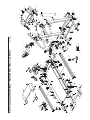
1
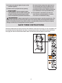
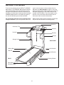
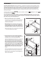
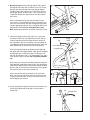
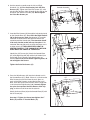
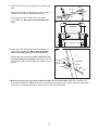
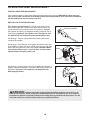
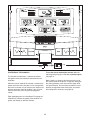
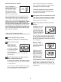
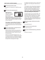
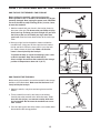
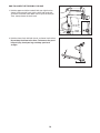
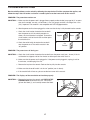
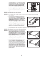
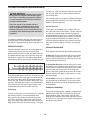
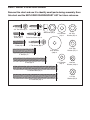
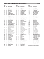
Model No. WETL27905.1
Serial No.
USER'S MANUAL
Serial
Number
Decal
QUESTIONS?
As a manufacturer, we are committed to providing complete
customer satisfaction. If you
have questions, or if there are
missing or damaged parts,
please call:
08457 089 009
or write:
ICON Health & Fitness, Ltd.
Customer Service Department
Unit 4
Revie Road Industrial Estate
Revie Road
Beeston
Leeds, LS118JG
UK
email: [email protected]
CAUTION
Read all precautions and instructions in this manual before
using this equipment. Save this
manual for future reference.
TABLE OF CONTENTS
IMPORTANT PRECAUTIONS . . . . . . . . . . . . . . . . . . . . . . . . . . . . . . . . . . . . . . . . . . . . . . . . . . . . . . . . . . . . . . . .3
BEFORE YOU BEGIN . . . . . . . . . . . . . . . . . . . . . . . . . . . . . . . . . . . . . . . . . . . . . . . . . . . . . . . . . . . . . . . . . . . . . .5
ASSEMBLY . . . . . . . . . . . . . . . . . . . . . . . . . . . . . . . . . . . . . . . . . . . . . . . . . . . . . . . . . . . . . . . . . . . . . . . . . . . . . . .6
OPERATION AND ADJUSTMENT . . . . . . . . . . . . . . . . . . . . . . . . . . . . . . . . . . . . . . . . . . . . . . . . . . . . . . . . . . . .10
HOW TO FOLD AND MOVE THE TREADMILL . . . . . . . . . . . . . . . . . . . . . . . . . . . . . . . . . . . . . . . . . . . . . . . . . .15
TROUBLESHOOTING . . . . . . . . . . . . . . . . . . . . . . . . . . . . . . . . . . . . . . . . . . . . . . . . . . . . . . . . . . . . . . . . . . . . .17
CONDITIONING GUIDELINES . . . . . . . . . . . . . . . . . . . . . . . . . . . . . . . . . . . . . . . . . . . . . . . . . . . . . . . . . . . . . . .19
ORDERING REPLACEMENT PARTS . . . . . . . . . . . . . . . . . . . . . . . . . . . . . . . . . . . . . . . . . . . . . . . . . .Back Cover
Note: A PART IDENTIFICATION CHART, an EXPLODED DRAWING, and a PART LIST are attached in the
centre of this manual.
WESLO is a registered trademark of ICON IP, Inc.
2
IMPORTANT PRECAUTIONS
WARNING:
To reduce the risk of burns, fire, electric shock, or injury to persons, read the
following important precautions and information before operating the treadmill.
1. It is the responsibility of the owner to ensure
that all users of this treadmill are adequately
informed of all warnings and precautions.
ASTA approved BS1362 type should be fitted
to the fuse carrier. A 13 amp fuse should be
used.
2. Use the treadmill only as described.
12. If an extension cord is needed, use only a 3conductor, 1mm2 (14-gauge) cord that is no
longer than 1.5 m.
3. Keep the treadmill indoors, away from moisture and dust. Do not put the treadmill in a
garage or covered patio, or near water.
13. Keep the power cord away from heated
surfaces.
4. Place the treadmill on a level surface, with at
least 2.5 m (8 ft.) of clearance behind it and
0.5 m (2 ft.) on each side. Do not place the
treadmill on a surface that blocks any air
openings. To protect the floor or carpet from
damage, place a mat under the treadmill.
14. Do not change the incline of the treadmill by
placing objects under the treadmill.
15. Never move the walking belt whilst the power
is turned off. Do not operate the treadmill if
the power cord or plug is damaged, or if the
treadmill is not working properly. (See TROUBLESHOOTING on page 17 if the treadmill is
not working properly.)
5. Do not operate the treadmill where aerosol
products are used or where oxygen is being
administered.
6. Keep children under the age of 12 and pets
away from the treadmill at all times.
16. Read, understand, and test the emergency
stop procedure before using the treadmill (see
OPERATION AND ADJUSTMENT on page 10).
7. The treadmill should be used only by persons
weighing 115 kg (250 lbs.) or less.
17. Never start the treadmill whilst you are standing on the walking belt. Always hold the
handrails whilst using the treadmill.
8. Never allow more than one person on the
treadmill at a time.
18. The treadmill is capable of high speeds.
Adjust the speed in small increments to avoid
sudden jumps in speed.
9. Wear appropriate exercise clothes when
using the treadmill. Do not wear loose clothes
that could become caught in the treadmill.
Athletic support clothes are recommended for
both men and women. Always wear athletic
shoes. Never use the treadmill with bare feet,
wearing only stockings, or in sandals.
19. The pulse sensor is not a medical device.
Various factors, including the user’s movement, may affect the accuracy of heart rate
readings. The pulse sensor is intended only as
an exercise aid in determining heart rate
trends in general.
10. Do not attempt to raise, lower, or move the
treadmill until it is properly assembled. (See
ASSEMBLY on page 6, and HOW TO FOLD
AND MOVE THE TREADMILL on page 16.)
You must be able to safely lift 20 kg (45 lbs) to
raise, lower, or move the treadmill.
20. Never leave the treadmill unattended whilst it
is running. Always remove the key, unplug
the power cord, and move the on/off switch to
the off position when the treadmill is not in
use. (See the drawing on page 5 for the location of the on/off switch.)
11. When connecting the power cord (see page
10), plug the power cord into an earthed circuit. No other appliance should be on the
same circuit. When replacing the fuse, an
21. When folding or moving the treadmill, make
sure that the storage latch is fully closed.
3
this manual. Never remove the motor hood unless instructed to do so by an authorised service representative. Servicing other than the
procedures in this manual should be performed
by an authorised service representative only.
22. Inspect and properly tighten all parts of the
treadmill regularly.
23. Never insert any object into any opening.
24.
DANGER:
Always unplug the power
cord immediately after use, before cleaning the
treadmill, and before performing the maintenance and adjustment procedures described in
25. The treadmill is intended for in-home use
only. Do not use the treadmill in a commercial, rental, or institutional setting.
WARNING:
Before beginning this or any exercise program, consult your physician. This
is especially important for persons over the age of 35 or persons with pre-existing health problems.
Read all instructions before using. ICON assumes no responsibility for personal injury or property
damage sustained by or through the use of this product.
SAVE THESE INSTRUCTIONS
The decal shown below has been placed on the treadmill. If the decal is missing, or if it is not legible, call
our Customer Service Department and order a free replacement decal (see the back cover of this manual). Apply the decal in the location shown. Note: The decal may not be shown at actual size.
178425
4
BEFORE YOU BEGIN
Thank you for selecting the new WESLO® CADENCE
900 treadmill. The CADENCE 900 treadmill combines
advanced technology with innovative design to help
you get the most from your exercise in the privacy of
your home. And when you’re not exercising, the unique
CADENCE 900 treadmill can be folded up, requiring
less than half the floor space of other treadmills.
ing this manual, please call our Customer Service
Department at 08457 089 009. To help us assist you,
please note the product model number and serial number before contacting us. The model number of the
treadmill is WETL27905.1. The serial number can be
found on a decal attached to the treadmill (see the
front cover of this manual for the location).
For your benefit, read this manual carefully before
using the treadmill. If you have questions after read-
Before reading further, please familiarise yourself with
the parts that are labelled in the drawing below.
Bookrack
Accessory Tray
Console
Handrail
Key/Clip
Upright
Storage Latch
RIGHT SIDE
Walking Belt
On/Off Switch
Foot Rail
Circuit Breaker
BACK
Walking Platform
Rear Roller
Adjustment Bolts
5
ASSEMBLY
Assembly requires two persons. Set the treadmill in a cleared area and remove all packing materials. Do not
dispose of the packing materials until assembly is completed. Note: The underside of the treadmill walking belt is
coated with high-performance lubricant. During shipping, a small amount of lubricant may be transferred to the
top of the walking belt or the shipping carton. This is a normal condition and does not affect treadmill performance. If there is lubricant on top of the walking belt, simply wipe off the lubricant with a soft cloth and a mild,
non-abrasive cleaner.
Assembly requires the included hex keys
and needlenose pliers
.
and your own phillips screwdriver
, wire cutters
For help identifying the assembly hardware, see the PART IDENTIFICATION CHART in the centre of this
manual. Note: The assembly hardware and other small parts are packaged in separate part bags. Do not
open the part bags until instructed to do so.
1. Make sure that the power cord is unplugged.
1
60
Place the Base (79) in the position shown, with the indicated small holes on top. Next, place the Wheels (63)
into the ends of the Base.
60
73
61
Open part bag A. Attach the Wheels (63) to the Base
(79) with 2” Bolts (61) and Wheel Nuts (64). Make sure
that the Wheel Nuts are on the sides shown; do not
overtighten the Bolts; the Wheels should turn freely.
Attach the four Base Pads (73) to the Base (79) with four
1” Tek Screws (60) (three are shown).
73
Small Hole
79
64
60
63
73
64
63
61
2. Raise the Base (79) to a vertical position, and hold it
near the treadmill Frame (96) as shown. Make sure that
the Wheels (63) are in the indicated position.
2
57
Identify the Right Upright (104), which has a large round
hole in the indicated location. Feed the Wire Harness
(65) into the hole and out of the top of the Right Upright.
Make sure that there are two U-nuts (74) in the lower
end of the Right Upright (see drawing 2a). Hold the Right
Upright against the Base (79) as shown. Make sure that
the Right Upright is oriented so the pivot hole is in the
position shown. Hand tighten two 3” Bolts (58) with two
5/16” Star Washers (57) into the Base and the Right
Upright.
58
47
79
58
104
Pivot
Holes
57
Attach the Left Upright (47) to the Base (79) in the same
way. Note: There is not a wire harness on the left side.
With the help of a second person, raise the Uprights (47,
104) to a vertical position.
Round
Hole
2a
104
96
65
63
74
6
3. Open part bag B. Hold an Upright Spacer (59) against
one side of the Frame (96) as shown. Insert a 4” Frame
Bolt (54) into the indicated hole in the Upright Spacer
and the Frame. Next, tighten a 3/4” Tek Screw (9) into
the Upright Spacer and the Frame. Then, remove the 4”
Frame Bolt. Repeat this procedure on the other side of
the Frame.
3
104
55 12
9
54
59
96
Have a second person lift the front end of the Frame
(96). Insert a 4” Frame Bolt (54) with a 3/8” Washer (12)
and a 3/8” Star Washer (55) into the Right Upright (104)
and the right Upright Spacer (59), and tighten the Frame
Bolt into the Frame. Do not overtighten the Frame
Bolt. Repeat this procedure on the left side of the Frame.
4. Identify the Right Handrail (40), which has a pulse bar
bracket on its left side. Feed the Wire Harness (65) up
into the large bracket on the Right Handrail and out of
the large hole in the left side. (Note: It may be helpful to
use needlenose pliers to pull the Wire Harness out of the
hole.) Remove any nylon ties from the large bracket.
Hole
4
40
Pulse Bar Bracket
Large Bracket
Insert the large bracket on the Right Handrail (40) into
the upper end of the Right Upright (104). Attach the Right
Handrail with two 1” Bolts (43), two 1/4” Washers (44),
two 1/4” Star Washers (45), a 4” Handrail Bolt (78), and a
5/16” Washer (106) as shown. Do not tighten the Bolts
yet.
See drawing 4a. Insert the included nylon tie through the
indicated hole in the Right Handrail (40). See drawing 4b.
Look into the Right Handrail and make sure that the Wire
Harness (65) is secured to the side shown. Then, tighten
the nylon tie and cut the excess off the end.
Large
Hole
65
43
44
45
104
45
43 44
78
106
4a
Attach the Left Handrail (not shown) in the same way.
Note: You may need to tip the Left Handrail to one side
as you insert the bracket. There is not a wire harness in
the left Upright (not shown).
4b
Tie
Tie
40
40
65
5. Attach the end of the ground wire to the small hole in the
side of the Right Handrail (40) with a Silver Ground
Screw (66).
5
66
40
7
Ground Wire
6. Set the console assembly onto the Left and Right
Handrails (13, 40). Be careful not to pinch the Wire
Harness (65). Tighten two Pulse Bar Screws (37), with
two #10 Star Washers (108), through the brackets on the
Handrails and into the Pulse Bar (39). Do not tighten
the Pulse Bar Screws yet.
6
Console Assembly
13
40
65
108
108
37
7. Insert the Wire Harness (65) through the indicated nylon tie
on the Console Base (67). Next, touch the Right Handrail
(40) to discharge any static. See drawing 7a. Insert the
connector on the end of the Wire Harness into the red
socket beneath the Console (69). The connector should
slide easily into the socket and snap into place. If the
connector does not slide easily and snap into place, turn it
and then insert it. IF THE CONNECTOR IS NOT INSERTED PROPERLY, THE CONSOLE MAY BE DAMAGED WHEN THE POWER IS TURNED ON.
39
37
7
65
40
Tie
67
37
Identify the 3/4” Screws (38). Attach the Console Base
(67) to the Right Handrail (40) and the Left Handrail (not
shown) with six 3/4” Screws (only three Screws are
shown). Start all six Screws before tightening them; do
not overtighten the Screws.
38
7a
69
Tighten the Pulse Bar Screws (37).
65
8. Press the Wire Harness (65) into the indicated track in
the Console Base (67). (Note: If there is a cylinder on the
Wire Harness that will not fit into the track, press as
much of the Wire Harness as possible into the track.)
Next, insert the excess Wire Harness into the large hole
in the side of the Right Handrail (40). Securely tighten
the nylon tie to prevent the Wire Harness from slipping, and then cut off the end of the nylon tie.
8
67
40
65
84
38
Attach the Access Door (84) to the Console Base (67) with
the 3/4” Screw (38).
Tie
See step 4. Tighten, but do not overtighten, the 1”
Bolts (43) and the 4” Handrail Bolts (78).
8
Track
9. Lower the Handrails (40, 13) until they are touching the
floor.
9
54
40, 13
58
See drawing 9a. Position the Handrails (40, 13) so the
treadmill Frame (96) is centered between them.
Firmly tighten the four 3” Bolts (58) and the two 4”
Frame Bolts (54). Be careful not to overtighten the
Bolts.
96
9a
Top View
13
40
96
10. Attach the Latch Housing (46) to the Left Upright (47)
with two 3/4” Screws (38). Make sure that the large
hole in the Latch Housing is on the side shown.
Remove the knob from the pin. Make sure that the collar and the spring are on the pin. Insert the pin into the
Latch Housing (46), and then tighten the knob back onto
the pin.
10
47
Large Hole
Knob
38
46
Spring
Collar
Pin
11.Make sure that all parts are properly tightened before you use the treadmill. Note: Extra hardware may
be included. Keep the included hex keys in a secure place; the large hex key is used to adjust the walking belt
(see page 18). To protect the floor or carpet, place a mat under the treadmill.
9
OPERATION AND ADJUSTMENT
THE PRE-LUBRICATED WALKING BELT
Your treadmill features a walking belt coated with high-performance lubricant. IMPORTANT: Never apply silicone spray or other substances to the walking belt or the walking platform. Such substances will deteriorate the walking belt and cause excessive wear.
HOW TO PLUG IN THE POWER CORD
This product must be earthed. If it should malfunction or break
down, earthing provides a path of least resistance for electric current to reduce the risk of electric shock. This product is equipped
with a power cord having an equipment-earthing conductor and an
earthing plug. Important: If the power cord is damaged, it must
be replaced with a manufacturer-recommended power cord.
1
Socket on treadmill
See drawing 1. Plug the indicated end of the power cord into the
socket on the treadmill.
See drawing 2. Press the pins on the power cord into the metal clips
in the adapter as shown. Close the adapter cover over the end of the
power cord and tighten the screw in the adapter. Important: Make
sure that the adapter cover is secure and the screw has been
tightened before using the power cord.
FR/SP
2
Adapter
Cover
Screw
Pins
Adapter
See drawing 3. Plug the power cord into an appropriate outlet that is
properly installed and earthed in accordance with all local codes and
ordinances. Important: The treadmill is not compatible with
GFCI-equipped outlets.
3
FR/
Metal
Clips
Outlet
IT
DANGER:
Improper connection of the equipment-earthing conductor can result in an increased risk of electric shock. Check with a qualified electrician or serviceman if you are in doubt as
to whether the product is properly earthed. Do not modify the plug provided with the product—if it will
not fit the outlet, have a proper outlet installed by a qualified electrician.
FR/SP
10
GR
IT
Clip
Key
FEATURES OF THE CONSOLE
To use the manual mode of the console, follow the
steps beginning on page 12. To use a speed program,
The treadmill console offers a selection of featuresETWE27905
see page 14.
designed to make your workouts more effective and
enjoyable.
Note: If there is a sheet of clear plastic on the face of
the console, peel off the plastic. To prevent damage to
When the manual mode of the console is selected, the
the walking platform, wear clean athletic shoes while
speed and incline of the treadmill can be changed with
using the treadmill. The first time the treadmill is used,
the touch of a button. As you exercise, the displays will
observe the alignment of the walking belt, and center
provide continuous exercise feedback. You can even
the walking belt if necessary (see page 18).
measure your heart rate using the handgrip pulse
sensor.
Eight speed programs are also offered. Each program
automatically controls the speed of the treadmill as it
guides you through an effective workout.
11
HOW TO TURN ON THE POWER
Plug in the power cord
(see page 10). Next, locate
the on/off switch on the
right side of the treadmill
frame near the right upright. Make sure that the
switch is in the “on” position.
pressed, the speed setting will change by 0.1
mph. If a button is held down, the speed setting
will change in increments of 0.5 mph.
On
Position
To stop the walking belt, press the Stop button.
The Time/Pace display will begin to flash. To
restart the walking belt, press the Start button or
the Speed increase button.
4
Next, stand on the foot rails of the treadmill. Find the
clip attached to the key (see the drawing on page 11)
and attach the clip securely to the waistband of your
clothes. Then, insert the key into the console. After a
moment, the displays will light. Important: In an emergency situation, the key can be pulled from the
console, causing the walking belt to slow to a stop.
Test the clip by carefully taking a few steps backward until the key is pulled from the console. If the
key is not pulled from the console, adjust the position of the clip as needed.
To change the incline of the treadmill, hold down
the Incline increase or decrease button until the
desired incline level is reached.
5
Insert the key fully into the console.
See HOW TO TURN ON THE POWER above.
2
Select the manual mode.
Distance display—
This display shows the
distance that you have
walked or run.
When the key is inserted, the manual
mode will be selected
and a track will appear
in the center of the console. If you have selected a program, remove the key and then reinsert it to select the
manual mode.
3
Follow your progress with the track and the
displays.
The track—The track in
the center of the console represents a distance of 1/4 mile (400
meters). As you walk or
run on the treadmill, the
indicators around the
track will light in succession until the entire track is
lit. The track will then darken and the indicators
will again begin to light in succession. The center
of the track will show the number of laps that you
have completed.
HOW TO USE THE MANUAL MODE
1
Change the incline of the treadmill as desired.
Time/Pace display—
When the manual
mode is selected, this
display will show the
elapsed time and your
Indicator
pace (pace is measured in minutes per
mile or minutes per kilometer). The display will alternate between one number and the other every
few seconds, as shown by the indicators in the
display. When a speed program is selected, the
display will show the time remaining in the program
and your pace.
Press the Start button or the Speed increase
button to start the walking belt.
A moment after the button is pressed, the walking
belt will begin to move at 1 mph. Hold the handrails
and begin walking.
As you exercise, change the speed of the walking
belt as desired by pressing the Speed increase
and decrease buttons. Each time a button is
12
Pulse display—This
display shows your
heart rate when you
use the pulse sensor
(see step 6).
Important: If a “d” appears in the Speed display, the console is in
the “demo” mode. This
mode is intended to be
used only while a
treadmill is displayed in a store. While the console
is in the demo mode, the power cord can be
plugged in, the key can be removed from the console, and the indicators and the displays will automatically light in a preset sequence. The buttons
on the console will not operate. If a “d” appears,
press the Speed decrease button so the “d”
disappears.
Fat/Calories
display—This display
shows the approximate
numbers of fat calories
and calories you have
burned (see FAT
BURNING on page 19). The display will alternate
between one number and the other every few seconds, as shown by the indicators in the display.
To exit the information mode at any time, remove
the key from the console.
Speed display—This
display shows the
speed of the walking
belt.
6
Measure your heart rate if desired.
Before using the
handgrip pulse
sensor, remove
the sheets of clear
plastic from the
metal contacts. In
addition, make
sure that your
hands are clean.
Note: The console can display speed and distance in either miles or kilometers. The letters
“MPH” or “Km/H” will appear in the Speed display
to show which unit of measurement is selected.
To change the unit of measurement, first select
the console’s information mode by holding down
the Stop button, inserting the key into the
console, and then releasing the Stop button.
An “E” for English miles
or an “M” for metric
kilometers will appear
in the Fat/Calories display. Press the Speed increase button to change the unit of measurement.
Metal Contacts
To measure your heart rate, stand on the foot
rails and hold the metal contacts—avoid moving
your hands. When your pulse is detected, the
heart symbol in the Pulse display will flash, one or
two dashes will appear, and then your heart rate
will be shown. For the most accurate heart rate
reading, continue to hold the contacts for about
15 seconds.
While the information
mode is selected, the
Distance display will
show the total number
of miles (or kilometers)
that the walking belt
has moved, and the
Time/Pace display will
show the total number
of hours that the treadmill has been used.
7
When you are finished exercising, remove the
key.
Step onto the foot rails, press the Stop button, and
adjust the incline of the treadmill to the lowest
level. The incline must be at the lowest level
when the treadmill is raised to the storage position or the treadmill will be damaged. Next,
remove the key from the console and put the key
in a secure place.
When you are finished using the treadmill, switch
the on/off switch to the “off” position.
13
The program will continue in this way until the last
period ends. The walking belt will then slow to a
stop.
HOW TO USE A SPEED PROGRAM
1
Insert the key into the console.
To change the incline setting during the program,
press the Incline buttons. If the speed setting is
too high or too low during the program, you can
manually override the setting by pressing the
Speed buttons. However, when the next period
begins, the treadmill will automatically adjust
to the speed setting for the next period.
See HOW TO TURN ON THE POWER on page
12.
2
Select one of the speed programs.
When the key is inserted, the manual
mode will be selected.
To select a speed program, press the
Program button repeatedly until one of the eight speed program indicators lights. Note: The graphs beside the indicators
show how the speed of the treadmill will change
during the programs.
To stop the program, press the Stop button. The
Time/Pace display will begin to flash. To restart
the program, press the Start button or the Speed
increase button. The walking belt will begin to
move at 1 mph. When the next period begins, the
treadmill will automatically adjust to the speed setting for the next period.
4
Each program consists of either 30 or 60 oneminute periods. One speed setting is programmed
for each period. Note: The same speed setting
may be programmed for two or more consecutive
periods.
3
Follow your progress with the track and the
displays.
See step 5 on page 12.
5
Press the Start button or the Speed increase
button to start the program.
Measure your heart rate if desired.
See step 6 on page 13.
6
When the button is pressed, the treadmill will automatically adjust to the speed setting that is programmed for the first period. Hold the handrails
and begin walking.
When you are finished exercising, remove the
key.
See step 7 on page 13.
When the first period of the program ends, a series of tones will sound. If a different speed setting
is programmed for the second period, the Speed
display will flash three times to alert you, and then
the speed of the walking belt will change.
14
HOW TO FOLD AND MOVE THE TREADMILL
HOW TO FOLD THE TREADMILL FOR STORAGE
Before folding the treadmill, adjust the incline to the
lowest position. If this is not done, the treadmill may be permanently damaged. Next, unplug the power cord. CAUTION:
You must be able to safely lift 20 kg (45 lbs.) to raise, lower,
or move the treadmill.
1. Hold the treadmill with your hands in the location shown by
the arrow at the right. To decrease the possibility of injury,
bend your legs and keep your back straight. As you raise
the frame, make sure to lift with your legs rather than
your back. Raise the frame about halfway to the vertical position.
2. Move your right hand to the position shown and hold the
treadmill firmly. Using your left hand, pull the latch knob to
the left and hold it. Raise the frame until it is past the latch
pin. Slowly release the latch knob. Make sure that the
frame is securely held by the latch pin.
To protect the floor or carpet from damage, place a mat
under the treadmill. Keep the treadmill out of
direct sunlight. Do not leave the treadmill in the storage
position in temperatures above 30° C (85° F).
Engaged
Frame
Latch
Knob
Latch Pin
HOW TO MOVE THE TREADMILL
Before moving the treadmill, convert the treadmill to the storage
position as described above. Make sure that the frame is securely held by the lock pin.
1. Hold the handrails, and place one foot against one of the
wheels.
2. Tilt the treadmill back until it rolls freely on the wheels.
Carefully move the treadmill to the desired location. To reduce the risk of injury, use extreme caution while moving the treadmill. Do not move the treadmill over an uneven surface.
3. Place one foot against one of the wheels, and carefully lower
the treadmill to the storage position.
15
Handrails
Wheel
Base
HOW TO LOWER THE TREADMILL FOR USE
1. Hold the upper end of the treadmill with your right hand as
shown. Using your left hand, pull the latch knob to the left
and hold it. Pivot the frame down until it is past the latch pin.
Then, slowly release the latch knob.
Latch
Knob
2. Hold the frame firmly with both hands, and lower it to the floor.
Do not drop the frame to the floor. To decrease the possibility of injury, bend your legs and keep your back
straight.
16
TROUBLESHOOTING
Most treadmill problems can be solved by following the steps below. Find the symptom that applies, and
follow the steps listed. If further assistance is needed, please see the front cover of this manual.
PROBLEM: The power does not turn on
SOLUTION: a. Make sure that the power cord is plugged into a properly earthed outlet (see page 10). If an extension cord is needed, use only a 3-conductor, 1 mm2 (14-gauge) cord that is no longer than 1.5 m
(5 ft.). Important: The treadmill is not compatible with GFCI-equipped outlets.
b. After the power cord has been plugged in, make sure that the key is fully inserted into the console.
c. Check the circuit breaker located on the treadmill
near the power cord. If the switch protrudes as
shown, the circuit breaker has tripped. To reset the
circuit breaker, wait for five minutes and then press
the switch back in.
c
d. Check the on/off switch located on the treadmill
near the power cord. The switch must be in the
“on” position.
d
Tripped
Reset
On
Position
PROBLEM: The power turns off during use
SOLUTION: a. Check the circuit breaker located on the treadmill near the power cord (see c. above). If the circuit breaker has tripped, wait for five minutes and then press the switch back in.
b. Make sure that the power cord is plugged in. If the power cord is plugged in, unplug it, wait for
five minutes, and then plug it back in.
c. Remove the key from the console. Reinsert the key fully into the console.
d. Make sure that the on/off switch is in the “on” position (see d. above).
e. If the treadmill still will not run, please see the front cover of this manual.
PROBLEM: The displays of the console do not function properly
SOLUTION: a. Remove the key from the console and UNPLUG THE
POWER CORD. Remove the four 3/4” Tek Screws
(9) from the Hood (1), and carefully remove the Hood.
a
9
1
17
Locate the Reed Switch (16) and the Magnet (10) on
the left side of the Pulley (101). Turn the Pulley until
the Magnet is aligned with the Reed Switch. Make
sure that the gap between the Magnet and the
Reed Switch is about 3 mm (1/8 in.). If necessary,
loosen the indicated 3/4” Tek Screws (9), move the
Reed Switch slightly, and then retighten the Screw.
Reattach the Hood (not shown), and run the treadmill
for a few minutes to check for a correct speed reading.
3 mm
9
101
16
10
Top View
PROBLEM: The walking belt slows when walked on
SOLUTION: a. If an extension cord is needed, use only a 3-conductor, 1mm2 (14-gauge) cord that is no longer
than 1.5 m (5 ft.).
b. If the walking belt is overtightened, treadmill performance may decrease and the walking belt may become damaged. Remove the key and UNPLUG THE
POWER CORD. Using the hex key, turn both rear
roller bolts counterclockwise, 1/4 of a turn. When the
walking belt is properly tightened, you should be able
to lift each edge of the walking belt 8 to 10 cm (3 to 4
in.) off the walking platform. Be careful to keep the
walking belt centred. Then, plug in the power cord, insert the key, and run the treadmill for a few minutes.
Repeat until the walking belt is properly tightened.
b
8–10 cm
Rear Roller Bolts
c. If the walking belt still slows when walked on, please see the front cover of this manual.
PROBLEM: The walking belt is off-centre or slips when walked on
SOLUTION: a. If the walking belt is off-centre, remove the key and
UNPLUG THE POWER CORD. If the walking belt
has shifted to the left, use the hex key to turn the left
rear roller bolt clockwise 1/2 of a turn; if the walking
belt has shifted to the right, turn the left rear roller
bolt counterclockwise 1/2 of a turn. Be careful not to
overtighten the walking belt. Then, plug in the power
cord, insert the key, and run the treadmill for a few
minutes. Repeat until the walking belt is centred.
b. If the walking belt slips when walked on, first remove
the key and UNPLUG THE POWER CORD. Using
the hex key, turn both rear roller bolts clockwise, 1/4
of a turn. When the walking belt is correctly tightened,
you should be able to lift each edge of the walking
belt 8 to 10 cm (3 to 4 in.) off the walking platform. Be
careful to keep the walking belt centred. Then, plug in
the power cord, insert the key, and walk on the treadmill for a few minutes. Repeat until the walking belt is
properly tightened.
18
a
b
CONDITIONING GUIDELINES
WARNING:
Before beginning this
or any exercise program, consult your physician. This is especially important for individuals over the age of 35 or individuals with preexisting health problems.
The pulse sensor is not a medical device.
Various factors, including the user’s movement, may affect the accuracy of heart rate
readings. The pulse sensor is intended only as
an exercise aid in determining heart rate trends
in general.
The following guidelines will help you to plan your exercise program. For more detailed exercise information, obtain a reputable book or consult your physician.
is to burn fat, adjust the speed and incline of the treadmill until your heart rate is near the lowest number in
your training zone.
For maximum fat burning, adjust the speed and incline
of the treadmill until your heart rate is near the middle
number in your training zone.
Aerobic Exercise
If your goal is to strengthen your cardiovascular system, your exercise must be “aerobic.” Aerobic exercise
is activity that requires large amounts of oxygen for
prolonged periods of time. This increases the demand
on the heart to pump blood to the muscles, and on the
lungs to oxygenate the blood. For aerobic exercise,
adjust the speed and incline of the treadmill until your
heart rate is near the highest number in your training
zone.
EXERCISE INTENSITY
WORKOUT GUIDELINES
Whether your goal is to burn fat or to strengthen your
cardiovascular system, the key to achieving the
desired results is to exercise with the proper intensity.
The proper intensity level can be found by using your
heart rate as a guide. The chart below shows recommended heart rates for fat burning and aerobic exercise.
To find the proper heart rate for you, first find your age
near the bottom of the chart (ages are rounded off to
the nearest ten years). Next, find the three numbers
above your age. The three numbers define your “training zone.” The lower two numbers are recommended
heart rates for fat burning; the higher number is the
recommended heart rate for aerobic exercise.
Each workout should include the following three parts:
A Warm-up—Start each workout with 5 to 10 minutes
of stretching and light exercise. A proper warm-up increases your body temperature, heart rate and circulation in preparation for exercise.
Training Zone Exercise—After warming up, increase
the intensity of your exercise until your pulse is in your
training zone for 20 to 60 minutes. (During the first few
weeks of your exercise program, do not keep your
pulse in your training zone for longer than 20 minutes.)
Breathe regularly and deeply as you exercise—never
hold your breath.
A Cool-down—Finish each workout with 5 to 10 minutes of stretching to cool down. This will increase the
flexibility of your muscles and will help prevent post-exercise problems.
EXERCISE FREQUENCY
Fat Burning
To burn fat effectively, you must exercise at a relatively
low intensity level for a sustained period of time.
During the first few minutes of exercise, your body
uses easily accessible carbohydrate calories for energy. Only after the first few minutes does your body
begin to use stored fat calories for energy. If your goal
To maintain or improve your condition, complete three
workouts each week, with at least one day of rest between workouts. After a few months, you may complete up to five workouts each week if desired. The key
to success is to make exercise a regular and enjoyable
part of your everyday life.
19
PART IDENTIFICATION CHART
Remove this chart and use it to identify small parts during assembly. Save
this chart and the EXPLODED DRAWING/PART LIST for future reference.
3/4” Screw (38)–9
3/4” Tek Screw (9)–2
Wheel Nut (64)–2
Silver Ground
Screw (66)–1
3/8” Washer
(12)–2
3/8” Star
Washer (55)–2
Pulse Bar Screw (37)–2
1” Bolt (43)–4
1” Tek Screw (60)–4
5/16” Washer
(106)–2
5/16” Star
Washer (57)–4
2” Bolt (61)–2
3” Bolt (58)–4
1/4” Washer
(44)–4
#10 Star
Washer (108)–2
4” Handrail Bolt (78)–2
1/4” Star
Washer (45)–4
4” Frame Bolt (54)–2
ORDERING REPLACEMENT PARTS
To order replacement parts, contact the ICON Health & Fitness, Ltd. office, or write:
ICON Health & Fitness, Ltd.
Customer Service Department
Unit 4, Revie Road Industrial Estate
Revie Road
Beeston
Leeds, LS118JG
UK
Tel:
08457 089 009
Outside the UK: (44) 0113 387 7133
Fax: (44) 0113 387 7125
To help us assist you, please be prepared to give the following information:
• the MODEL NUMBER of the product (WETL27905.1)
• the NAME of the product (WESLO CADENCE 900 treadmill)
• the SERIAL NUMBER of the product (see the front cover of this manual)
• the KEY NUMBER and DESCRIPTION of the desired part(s) (see the PART LIST and the EXPLODED
DRAWING in the centre of this manual)
Part No. 229882 R1105A
Printed in Canada © 2005 ICON IP, Inc.
PART LIST—Model No. WETL27905.1
Key
No. Qty.
1
2
3
4
5
6
7
8
9
10
11
12
13
14
15
16
17
18
19
20
21
1
3
2
2
4
4
4
2
24
1
1
2
1
2
1
1
1
1
1
4
3
22
1
23
24
25
26
27
28
29
30
31
32
33
34
35
36
37
38
39
40
41
1
2
1
1
14
1
1
1
1
1
1
1
1
2
2
25
1
1
1
Description
Hood
#8 Washer
Foot Rail
Belt Guide
1/2” Screw
Isolator
Platform Screw
Rubber Hood Mount
3/4” Tek Screw
Magnet
Reed Switch Clip
3/8” Washer
Left Handrail
Motor Bushing
Motor Pivot Nut
Reed Switch
Drive Motor
Pulley/Flywheel/Fan
Drive Motor Belt
Bracket Grommet
Motor Tension Bolt/
Upper Incline Bolt
Motor Tension Star
Washer
Motor Fan
Motor Tension Nut
Motor Pivot Bolt
Electronics Bracket
Electronics Screw
Filter
Receptical
Circuit Breaker
On/Off Switch
Controller
Incline Leg
Transformer
Ground Nut
Handrail Foam
Pulse Bar Screw
3/4” Screw
Pulse Bar
Right Handrail
Hex Key
Key
No. Qty.
42
43
44
45
46
47
48
49
50
51
52
53
54
55
56
57
58
59
60
61
62
63
64
65
66
67
68
69
70
71
72
4
4
13
4
1
1
1
2
2
1
1
1
2
2
2
4
4
2
4
2
2
2
4
1
1
1
1
1
1
1
1
73
74
75
76
77
78
79
80
81
82
83
4
4
1
2
1
2
1
1
1
1
1
Description
Cage Nut
1” Bolt
1/4” Washer
1/4” Star Washer
Latch Housing
Left Upright
Ground Bolt
Pulse Bar Screw
Rear Platform Screw
Motor Bracket
Motor Isolator
Latch Pin Assembly
4” Frame Bolt
3/8” Star Washer
Motor Bolt
5/16” Star Washer
3” Bolt
Upright Spacer
1” Tek Screw
2” Bolt
Base Endcap
Wheel
Wheel Nut
Wire Harness
Silver Ground Screw
Console Base
Book Lens
Console
Plastic Tie
Key Clip
Console Warning
Decal
Base Pad
U-nut
Incline Wire
Frame Plug
Frame Ground Wire
4” Handrail Bolt
Base
Outlet Adaptor
Belly Pan
Incline Motor
Power Cord
R1105A
Key
No. Qty.
84
85
86
87
88
89
90
91
92
93
94
95
96
97
98
99
100
101
102
103
104
105
1
4
2
1
1
2
4
2
4
1
3
2
1
1
1
1
1
1
1
1
1
1
106
107
108
109
110
111
112
#
#
#
#
#
#
#
#
#
#
#
2
1
2
2
1
1
1
1
1
1
1
1
1
1
1
2
1
1
Description
Access Door
Cable Tie Clamp
Frame U-nut
8” Cable Tie
Incline Stop Bracket
Rear Wheel Bolt
Incline Leg Nut
Rear Wheel
Plastic Fastener
Right Endcap
Roller Star Washer
Roller Adj. Bolt
Frame
Rear Roller
Left Endcap
Walking Belt
Walking Platform
Front Roller/Pulley
Warning Decal
Front Roller Adj. Bolt
Right Upright
Pulse Sensor
Assembly
5/16” Washer
5/32” Hex Key
#10 Star Washer
Incline Pivot Bolt
Belly Pan Cap
Rear Belly Pan
Lower Incline Bolt
10” Green Wire, F/Ring
8” Green Wire, F/Ring
4” Green Wire, F/Ring
12” Blue Wire, 2F
6” Blue Wire, M/F
8” Blue Wire, 2F
8” White Wire, 2F
6” Black Wire, M/F
4” Black Wire, 2F
8” Red Wire, M/F
User’s Manual
#These parts are not illustrated
95
89
91
44
94
50
9
76
82
109
98
41
107
64
112 88
21
9
90
33
6
9
90
94
44
92
102
95
97
90
64
75
93
1
7
9
76
4
92
50
5
3
9
91
9
9
89
6
9
109
100
9
7
92
11
101
111
16
10
96
7
9
99
59
18
19
9
3
9
6
15
86
52
14
17
56
21
7
4
24
22
5
8
9
44
9
86
21
25
51
23
24
94
83
6
32
103
80
44 81
9
110
9
8
9
105
38
87
9
59
27
26
20
53
49
105
39
EXPLODED DRAWING—Model No. WETL27905.1
27
28
34
105
61
27
38
105
85
27
63
29
38
36
20
46
64
79
58
57
27
2
27
30
31
44
43
45
13
55
54
108
37
38
73
60
12
38
63
77
27
66
73
40
48
2
36
64
74
60
43
65
38
44
47 78
106
42 45
R1105A
61
38
38
58
106
68
38
74
57
54
71
38
12
55
104
78
44
43
38
45
20
73
60
65
108
37
38
42
45
35
62
43
44
72
67
69
73
60
62
70
84
38
38
38