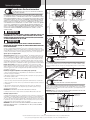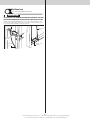
1
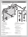
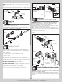
GARAGE DOORS & OPENERS
9700
To r q u e M a s t e r ® P l u s
Front Mount Low Headroom
MH
installation instructions and owner’s manual
Ta b l e
O f
C o n t e n t s
Parts Breakdown
Pre-Installation
Important Safety Instructions
Tools Required
Package Contents
Door Section Identification
Removing an Existing Door
Preparing the Opening
Installation
Optional Installation
TorqueMaster® Plus Reset Instructions
Door Arm Hookup
Inside Lock
Pull Down Rope
Maintenance
Cleaning Your Garage Door
Painting Your Garage Door
Operation and Maintenance
Warranty
Dealer Locator Information
2
3
3
3
3
4
4
4
6
14
14
14
14
15
16
16
16
16
17
18
IMPORTANT NOTICES!
Wayne-Dalton highly recommends that you read and fully understand the Installation Instructions and Owner’s Manual before you
attempt this installation.
To avoid possible injury, read the enclosed instructions carefully before installing and operating the garage door. Pay close attention
to all warnings and notes. After installation is complete, fasten this
manual near garage door for easy reference.
The complete Installation Instructions and Owner’s Manual are available at no charge from:
Wayne-Dalton, a Division Of Overhead Door Corporation,
P.O. Box 67, Mt. Hope, OH., 44660,
Or Online At www.Wayne-Dalton.com
©Copyright 2011 Wayne-Dalton, a Division Of Overhead Door Corporation
Part No. 343712
REV1 08/16/2011
Parts Breakdown
NOTE: The illustrations shown on this page are general
representations of the door parts. Each specific door
models may have unique variations.
J6.
J6.
J9.
C1.
A1.
J1.
A2.
J2.
F3.
J8.
J5.
F2.
F1.
I2.
G2.
K2.
H2.
G1.
E1.
J3.
H1.
J7.
C1.
B2.
A2.
F1.
F3.
F2.
Top of vertical
track
Top of vertical
track
E2.
B1.
B1. (Fully
Adjustable
Feature)
3rd hole
set
B1.
E3.
I4.
A1.
B2.
D4.
B1.
D3.
D2.
D1.
2nd
hole set
I1.
E4.
B2. (Quick
Install
Feature)
3rd
hole set
2nd
hole set
K1.
Top
hole
C2.
1st hole
set
C1.
I3.
Middle
hole
Bottom
hole
J6.
A. Flag Angles (As Required):
A1. Fully Adjustable (F.A.) Flag Angles
A2. Quick Install (Q.I.) Flag Angles
B. Jamb Brackets (As Required):
B1. Fully Adjustable (F.A.) Jamb Brackets
B2. Quick Install (Q.I.) Jamb Brackets
C. Track Rollers:
C1. Short Stem Track Rollers
C2. Long Stem Track Rollers
D. Graduated End Hinges:
D1. Single Graduated End Hinges (S.E.H.), Anti-Pinch
D2. Single Graduated End Hinges (S.E.H.), Industry Standard
D3. Double Graduated End Hinges (D.E.H.), Anti-Pinch
D4. Double Graduated End Hinges (D.E.H.), Industry Standard
E. Stacked Sections:
E1. Top Section
E2. Intermediate(s) Section
E3. Lock Section
E4. Bottom Section
F. Top Fixture Assemblies (As Required):
F1. Top Fixture Assemblies – For Models 9600/9400/9100/5140/5120
F2. Top Fixture Assemblies – For Model 9700
F3. Top Fixtures – For Model 9800
G. Strut(s) (As Required):
1st
hole set
Lower hole
of hole/
slot pattern
G1. Strut (U-shaped)
G2. Strut (A-symmetrical)
H. Drawbar Operator Bracket (For Trolley Operated Doors):
H1. Drawbar Operator Bracket – For Models 9600/9400/9100/5140/5120
H2. Drawbar Operator Bracket – For Models 9700/9800
Tracks:
I1. Left Hand Horizontal Track Assembly
I2. Right Hand Horizontal Track Assembly
I3. Left Hand Vertical Track
I4. Right Hand Vertical Track
J. TorqueMaster Plus® Spring Assembly:
J1. Center Bracket Bushing Assembly
J2. TorqueMaster® Spring Tube (Single Or Double Springs)
J3. Left Hand End Bracket
J4. Right Hand End Bracket (Disconnect Cable Guide)
J5. Left Hand Cable Drum Assembly
J6. Right Hand Cable Drum Assembly
J7. Loose Winding Shaft (Single Spring Only)
J8. Left Hand Drum Wrap (As Required)
J9. Right Hand Drum Wrap (As Required)
K. Rear Back Hangs:
K1. Left Hand Rear Back Hang Assemblies
K2. Right Hand Rear Back Hang Assemblies
2
Please Do Not Return This Product To The Store. Contact your local Wayne-Dalton dealer. To find your local Wayne-Dalton dealer,
refer to your local yellow pages business listings or go to the Find a Dealer section online at www.Wayne-Dalton.com
Pre-Installation
Important Safety Instructions
Tools Required
Definition of key words used in this manual:
• Power drill
• Drill bits: 1/8”, 3/16”,
7/16”
• Ratchet wrench
• Socket driver: 7/16”
• Sockets: 7/16”, 1/2”,
9/16”, 5/8”
• Socket extension: 3”
WARNING
Indicates a potentially hazardous situation which; if not avoided,
could result in severe or fatal injury.
Caution: Property damage or injury can result from failure to follow
instructions.
Important: Required step for safe and proper door operation.
Note: Information assuring proper installation of the door.
READ THESE INSTRUCTIONS CAREFULLY BEFORE ATTEMPTING INSTALLATION. IF IN QUESTION
ABOUT ANY OF THE PROCEDURES, DO NOT PERFORM THE WORK. INSTEAD, HAVE A TRAINED
DOOR SYSTEMS TECHNICIAN DO THE INSTALLATION OR REPAIRS.
• Phillips head
screwdriver
• Flat tip screwdriver
• Pliers/Wire cutters
• Needle nose pliers
• Locking Pliers
• (2) Vice clamps
• Wrenches: 7/16”,
1/2”, 9/16”, 5/8”
• Hammer
• Tape measure
• Step Ladder
• Level
• Pencil
• Leather gloves
• Safety glasses
Package Contents
1.
2.
3.
READ AND FOLLOW ALL INSTALLATION INSTRUCTIONS.
Wear protective gloves during installation to avoid possible cuts from sharp metal edges.
It is always recommended to wear eye protection when using tools, otherwise eye injury
could result.
4. Avoid installing your new door on windy days. Door could fall during the installation causing severe or fatal injury.
5. Doors 12’-0” wide and over should be installed by two persons, to avoid possible injury.
6. Operate door only when it is properly adjusted and free from obstructions.
7. If a door becomes hard to operate, inoperative or is damaged, immediately have necessary adjustments and/ or repairs made by a trained door system technician using proper
tools and instructions.
8. DO NOT stand or walk under a moving door, or permit anybody to stand or walk under an
electrically operated door.
9. DO NOT place fingers or hands into open section joints when closing a door. Use lift
handles/ gripping points when operating door manually.
10. DO NOT permit children to operate garage door or door controls. Severe or fatal injury
could result should the child become entrapped between the door and the floor.
11. Due to constant extreme spring tension, do not attempt any adjustment, repair or alteration to any part of the door, especially to springs, spring brackets, bottom corner brackets,
fasteners, counterbalance lift cables or supports. To avoid possible severe or fatal injury,
have any such work performed by a trained door systems technician using proper tools
and instructions.
12. On electrically operated doors, pull down ropes must be removed and locks must be
removed or made inoperative in the open (unlocked) position.
13. Top section of door may need to be reinforced when attaching an electric opener. Check
door and/ or opener manufacturer’s instructions.
14. Visually inspect door and hardware monthly for worn and or broken parts. Check to
ensure door operates freely.
15. Test electric opener’s safety features monthly, following opener manufacturer’s instructions.
16. NEVER hang tools, bicycles, hoses, clothing or anything else from horizontal tracks. Track
systems are not intended or designed to support extra weight.
17. This door may not meet the building code wind load requirements in your area. For your
safety, you will need to check with your local building official for wind load code requirements and building permit information.
After installation is complete, fasten this manual near the garage door.
Important: Stainless steel or pt2000 coated lag screws must be used when
installing center bearing brackets, end brackets, jamb brackets, drawbar operator mounting/ support brackets and disconnect brackets on treated lumber
(preservative-treated). Stainless steel or pt2000 lag screws are not necessary
when installing products on un-treated lumber.
Note: It is recommended that 5/16” lag screws are pilot drilled using a 3/16” drill bit, prior to
fastening.
Important: When installing 5/16” lag screws using an electric drill/ driver, the
drill/ drivers clutch must be set to deliver no more than 200 in-lbs of torque.
Fastener failure could occur at higher settings.
Note: Depending on the door model, some parts listed will not be supplied if not required. Rear
Back Hangs may not be included with your door.
Door sections (as required)
TorqueMaster® spring tube
Quick Install flag angles RH/LH
(as required)
Fully Adjustable flag angles RH/LH
(as required)
Vertical tracks RH/LH
Horizontal tracks RH/LH
ED
SIDE
VIEW
ENGAG
t Pawl
VIEW
Ratche
EATH
NDERN
Quick install jamb Fully Adjustable jamb
brackets (as required) brackets (as required)
(2) Top fixtures
Pull down
rope (if included)
Drawbar operator
bracket (if included)
Track rollers
(as required)
Center bracket
End brackets RH/LH bushing assembly
Cable drum
Drum wraps
assemblies RH/LH RH/LH (as required)
Weatherstrips & nails
(If included)
Loose winding
shaft (single
spring only)
WARNING
Prior to winding or making adjustments to the springs, ensure
you’re winding in the proper direction as stated in the Installation Instructions. Otherwise, the spring fittings may release
from spring if not wound in the proper direction and could
result in severe or fatal injury.
(2) 3/8”- 16 Hex nuts
Stud Plate
(as required) (2) 5/16”-18 Hex nuts
(2) 3/8”-16 x 3/4”
Truss head bolts
Important: Right and left hand is always determined from inside the building
looking out
1/4”- 20 Flanged
hex nuts (as required)
3
(2) 5/16” Washers
Please Do Not Return This Product To The Store. Contact your local Wayne-Dalton dealer. To find your local Wayne-Dalton dealer,
refer to your local yellow pages business listings or go to the Find a Dealer section online at www.Wayne-Dalton.com
1/4”-20 x 11/16” Self
drilling screws (as required)
WARNING
5/16” x 1 5/8” Hex head lag screws
(as required)
1/4”-20 x 9/16”
Track bolts (as required)
A powerful spring releasing its energy suddenly can cause severe
or fatal injury. To avoid injury, have a trained door systems technician, using proper tools and instructions, release the spring
tension.
1/4”-14 x 5/8” Self tapping
screws (as required)
For detailed information see supplemental instructions “Removing an Existing Door/ Preparing
the Opening”. These instructions are not supplied with the door, but are available at no charge
from Wayne-Dalton, A Division Of Overhead Door Corporation, P.O. Box 67, Mt. Hope, OH.,
44660, or at www.Wayne-Dalton.com.
(2) 5/16”-18 x 3/4”
Carriage bolts
Cotter pin
Preparing the Opening
IMPORTANT: If you just removed your existing door or you are installing a new
door, complete all steps in preparing the opening.
To ensure secure mounting of track brackets, side and center brackets, or steel angles to new or
retro-fit construction, it is recommended to follow the procedures outlined in DASMA technical
data sheets #156, #161 and #164 at www.dasma.com.
The inside perimeter of your garage door opening should be framed with wood jamb and header
material. The jambs and header must be securely fastened to sound framing members. It is
recommended that 2” x 6” lumber be used. The jambs must be plumb and the header level. The
jambs should extend a minimum of 12” (305 mm) above the top of the opening for TorqueMaster® counterbalance systems. For low headroom applications, the jambs should extend to the
ceiling height. Minimum side clearance required, from the opening to the wall, is 3-1/2” (89
mm).
Important: Closely inspect jambs, header and mounting surface. Any wood
found not to be sound, must be replaced.
For TorqueMaster® counterbalance systems, a suitable mounting surface (2” x 6”) must be firmly
attached to the wall, above the header at the center of the opening.
Note: Drill a 3/16” pilot hole in the mounting surface to avoid splitting the lumber. Do not attach
the mounting surface with nails.
Weatherstrips (may not be included):
Depending on the size of your door, you may have to cut or trim the weatherstrips (if necessary)
to properly fit into the header and jambs.
Note: If nailing product at 40°F or below, pre-drilling is required.
Note: Do not permanently attach weatherstrips to the header and jambs at this time.
For Quick Install track: For the header, align the weatherstrip with the inside edge of the header
and temporarily secure it to the header with equally spaced nails. Starting at either side of the
jamb, fit the weatherstrip up tight against the temporarily attached weatherstrip in the header
and flush with the inside edge of the jamb. Temporarily secure the weatherstrip with equally
spaced nails. Repeat for other side. This will keep the bottom section from falling out of the
opening during installation. Equally space nails approximately 12” to 18” apart.
For Fully Adjustable track: For the header, align the weatherstrip 1/8” to 1/4” inside the header
edge, and temporarily secure it to the header with equally spaced nails. Starting at either side
of the jamb, fit the weatherstrip up tight against the temporarily attached weatherstrip in the
header and 1/8” to 1/4” inside the jamb edge. Temporarily secure the weatherstrip with equally
spaced nails. Repeat for other side. This will keep the bottom section from falling out of the
opening during installation. Equally space nails approximately 12” to 18” apart.
Headroom requirement: Headroom is defined as the space needed above the top of the door
for tracks, springs, etc. to allow the door to open properly. If the door is to be motor operated,
2-1/2” (64 mm) of additional headroom is required.
Note: 6” low headroom conversion kit is available for 12” radius only. Contact your local
Wayne-Dalton dealer.
Backroom requirement: Backroom is defined as the distance needed from the opening back
into the garage to allow the door to open fully.
Backroom Requirements
5/16” x 1-1/4” Clevis pin
Door Section Identification
Graduated end and center hinges are always pre-attached at the top of each section (except
top section) and the graduated end hinges are stamped for identification, #1, #2, #3, and #4
(#4 only on five section doors). The stamp identifies the stacking sequence of the section. The
sequence is always determined by #1 being the bottom section to #3 or #4 being the highest
intermediate section. If the stamp on the graduated end hinge is illegible, refer to the section
side view illustration. The section side view illustration shows the graduated end hinge profile of
all sections, and can also be used to identify each section.
The BOTTOM SECTION can be identified by #1 graduated end hinges, the factory attached
bottom astragal, the factory attached bottom corner brackets and by the bottom corner bracket
warning labels on each end stile.
The LOCK SECTION can be identified by #2 graduated end hinges on a 4 section high door and
by #3 graduated end hinges on a 3 section high door. Also, on a 3 section door, the lock section
will come with a warning label attached to the right or left endstile.
The INTERMEDIATE SECTION can be identified by #3 graduated end hinges (Only on a 4
section high door). The section will have a warning label attached to either the right or left hand
end stile.
Note: #4 graduated end hinges are used on the fourth section of five section doors.
The TOP SECTION can be identified with no pre-installed graduated end or center hinges.
Warning label
Top section
1-3/8”
#3
Warning labels (Only on a 4 Section High Door)
Intermediate section
1-1/8”
#2
Warning labels (Only on a 3 Section High Door)
Lock section
#2 Graduated
end hinge
7/8”
#1
Bottom corner bracket warning labels
Bottom section
Bottom weather
seal
Typical graduated
end hinge
stamping location
#3 Graduated
end hinge
#1 Graduated
end hinge
Bottom corner
bracket
Bottom weather seal
Door Height
Track
Manual Lift
Motor Operated
6’0” to 7’0”
6” Low Headroom
102” (2591 mm)
125” (3175 mm)
7’1” to 8’0”
6” Low Headroom
114” (2896 mm)
137” (3480 mm)
Headroom Requirements
Section side view illustration
Track Type
Space Needed
6” Low Headroom
9” (229 mm)
Removing an Existing Door
Important: Counterbalance spring tension must always be released before any
attempt is made to start removing an existing door.
4
Please Do Not Return This Product To The Store. Contact your local Wayne-Dalton dealer. To find your local Wayne-Dalton dealer,
refer to your local yellow pages business listings or go to the Find a Dealer section online at www.Wayne-Dalton.com
Suitable mounting surface
2”x 6” lumber minimum
Headroom
Min. Side
room
Clearance
is 3 1/2”
Header board 2”x 6”
lumber preferred
der
Min. Side
room
Clearance
is 3 1/2”
ea
el h
Lev
Bac
kro
Nail
om
s
trip Finished
ers
Door
ath
e
W
Height
Plumb
jambs
ed
ish
Fin width
r
Doo
bs
Jam
Jamb
Quick Install track
Weatherstrips
Weatherstrips
Jamb
Fully Adjustable track 1/8” to 1/4”
5
Please Do Not Return This Product To The Store. Contact your local Wayne-Dalton dealer. To find your local Wayne-Dalton dealer,
refer to your local yellow pages business listings or go to the Find a Dealer section online at www.Wayne-Dalton.com
Vertical track
Installation
1st hole set
Before installing your door, be certain that you have read and followed all of the instructions covered in the pre-installation section of this manual. Failure to do so may result in an
improperly installed door.
NOTE: Reference TDS 160 for general garage door terminology at www.dasma.com.
1
Tools: None
Jamb Bracket Schedule
57.75”
(1467mm)
5
M
8
T
-
-
6’6”
63.50”
(1613mm)
3
B
6
M
-
-
6’8”
65.50”
(1664mm)
3
B
6
M
-
-
6’10”
67.00”
(1702mm)
3
B
6
M
-
-
7’0”
69.50”
(1765mm)
3
B
6
M
-
-
7’3”
72.50”
(1842mm)
3
B
7
T
8
T
7’6”
75.50”
(1918mm)
3
B
7
T
8
T
7’9”
78.50”
(1994mm)
3
B
7
T
8
T
8’0” (4 Sec)
81.50”
(2070mm)
3
B
7
T
8
T
Tools: None
3
4
Fully Adjustable Jamb Brackets
Tools: None
Note: If you have Quick Install jamb brackets, skip this step.
Note: If you have riveted track, skip this step.
Note: The bottom jamb bracket is always the shortest bracket, while the center jamb
bracket is the next tallest. If three jamb brackets per side are included with your door, you will
have received a top jamb bracket, which is the tallest.
To attach the bottom jamb bracket, locate lower hole of the hole/ slot pattern of the 1st hole
set on the vertical track. Align the slot in the jamb bracket with the lower hole of the hole/ slot
pattern. Secure jamb bracket using (1) 1/4”-20 x 9/16” track bolt and (1) 1/4”-20 flange hex
nut. Repeat for other side.
Place the center jamb bracket over the lower hole of the hole/ slot pattern that is centered
between the bottom jamb bracket and flag angle of the 2nd hole set. Secure jamb bracket
using (1) 1/4”-20 x 9/16” track bolt and (1) 1/4”-20 flange hex nut. Repeat for other side.
If a top jamb bracket was included, secure it to vertical track using the lower hole of the hole/
slot pattern in the 3rd hole set and (1) 1/4”-20 x 9/16” track bolt and (1) 1/4”-20 flange hex
nut. Repeat for other side.
Vertical track Top of track
Stud
plate
JAMB BKT POSITION JAMB BKT POSITION JAMB BKT POSITION
B= BOTTOM HOLE, M= MIDDLE HOLE, T= TOP HOLE
Flag angle
1/4”-20
Flange hex nuts
Fully Adjustable
vertical
track
3RD SET
6’0”
Fully Adjustable Flag Angles
Quick Install
vertical
track
2ND SET
TRACK
LENGTH
Lower
Quick
Install tab
Quick
Install
feature
Note: If you have Quick Install flag angles, skip this step.
Note: If you have riveted track, skip this step.
Note: Flag angles are right and left handed.
If you have Quick Install vertical tracks, hand tighten the left hand flag angle to the left hand
vertical track using (1) stud plate and (2) 1/4” – 20 flange hex nuts. Repeat for the other side.
If you have Fully Adjustable vertical tracks, hand tighten the left hand flag angle to the left
hand vertical track using (2) 1/4”-20 x 9/16” track bolts and (2) 1/4”-20 flange hex nuts.
Repeat for other side. Flange nuts will be secured after flag angle spacing is completed in
step, Top Section.
1ST SET
DOOR HEIGHT
1/4 Turn
Flag angle
1/4”-20
Flange hex nuts
Mounting flange
Q.I. jamb
bracket
Flag angle
2
Jamb bracket
in place
Q.I. tab
Note: If you have Fully Adjustable flag angles, skip this step.
Note: If you have riveted track, skip this step.
Note: Flag angles are right and left handed.
Place the lower Quick Install tab of the left hand flag angle in the Quick Install feature of the
left hand vertical track. Give the flag angle 1/4 turn to lock in place. Repeat for other side.
3rd hole set
Bottom hole
Middle hole
Top hole
Quick Install Flag Angles
Vertical
track
2nd hole set
Top of track
1/4”- 20 x 9/16”
Track bolts
Quick Install Jamb Brackets
Tools: None
1st hole set
Note: If you have Fully Adjustable jamb brackets, skip this step.
Note: If you have riveted track, skip this step.
Measure the length of the vertical tracks. Using the jamb bracket schedule, determine the
placement of the jamb brackets for your door height and track length. To install the jamb
brackets, align the Quick Install tab on the Quick Install jamb bracket with the Quick Install
feature in the vertical track and turn the bracket perpendicular to the track so the mounting
flange is toward the back (flat) leg of the track. Repeat for other side.
Lower hole of
hole/ slot pattern
2nd hole set
3rd hole set
1/4”- 20
Flange hex nut
F.A. jamb
bracket
6
Please Do Not Return This Product To The Store. Contact your local Wayne-Dalton dealer. To find your local Wayne-Dalton dealer,
refer to your local yellow pages business listings or go to the Find a Dealer section online at www.Wayne-Dalton.com
1/4”- 20 x
9/16”
Track bolt
Jamb bracket
in place
5
Cable Drum Assemblies and Track Rollers
Tools: None
NOTE: Refer to door section identification, located in the pre-installation section of this
manual or refer to Parts Breakdown on page 2.
NOTE: Cable drum assemblies are marked right and left hand.
Weather seal
WARNING
Failure to ensure tight fit of cable loop over milford pin could
result in counterbalance lift cable coming off the pin, allowing the door to fall, possibly resulting in severe or fatal
injury.
Level
Uncoil the counterbalance lift cables from the cable drum assemblies, making sure you place
the left hand cable loop on the left hand milford pin of the bottom corner bracket and the
right hand cable loop on the right hand milford pin of the bottom corner bracket.
NOTE: Check to ensure cable loops fits tightly over the milford pins.
Insert a short stem track roller into the bottom corner brackets and another into the #1
graduated end hinges at the top of the bottom section.
Note: Larger doors will use long stem track rollers with double graduated end hinges.
NOTE: Verify bottom weather seal is aligned with bottom section. If there is more than 1/2”
excess weather seal on either side, trim weather seal even with bottom section.
Counterbalance
lift cable
Long
stem
track
roller
Counterbalance
lift cable
Bottom corner
bracket
warning label
7
Vertical Tracks
Tools: Power Drill, 3/16” Drill bit, 7/16” Socket driver, Tape measure,
IMPORTANT: If your door is to be installed prior to a finishing construction
of the building’s floor, the vertical tracks and the door bottom section
assembly should be installed such that when the floor is constructed, no
door or track parts are trapped in the floor construction.
Important: The tops of the vertical tracks must be level from side to side.
If the bottom section was shimmed to level it, the vertical track on the
shimmed side must be raised the height of the shim.
Position the left hand vertical track assembly over the track rollers of the bottom section. Drill
3/16” pilot holes into the door jamb for the lag screws.
Loosely fasten jamb brackets and flag angle to the jamb using 5/16” x 1-5/8” lag screws.
Tighten lag screws, securing the bottom jamb bracket to jamb, maintain 3/8” to 5/8” spacing, between the bottom section and vertical track. Repeat same process for other side.
Double graduated
end hinge
(Hinge tube)
Bottom
section
Cable loop
Cable
loop
6
Short stem
track roller
Bottom
section
Wooden shims
(If necessary)
#1 Single
graduated
end hinge
(Hinge tube)
Left hand
cable drum
assembly
Milford
pin
Bottom section
Milford
pin
Bottom
corner
bracket
Short stem
track roller
Bottom
corner
bracket
Bottom
weather
seal
Flag
angle
Vertical
track
assembly
Bottom Section
Tools: Level, Wooden shims (if necessary)
5/16” x 1-5/8”
Lag screws
Jamb
bracket
12R FA 15R FA 12R QI 15R QI
Flag angle lag screw locations
Center the bottom section in the door opening. Level the section using wooden shims (if
necessary) under the bottom section.
Bottom
section
3/8” to 5/8”
Spacing
Track
rollers
Bottom section
Vertical track
Floor
8
Track roller
Stacking Sections
Tools: Power drill,7/16” Socket driver
Note: The sections can be identified by the graduation of the factory installed end hinges.
The smallest graduated end hinge on section should be stacked on top of the bottom section,
with each graduated end hinge increasing as the sections are stacked, see Parts Breakdown
on page 2.
Note: Make sure graduated end and center hinges are flipped down, when stacking another
section on top.
Note: Larger doors will use long stem track rollers with double graduated end hinges.
Place track rollers into graduated end hinges of remaining sections.
With assistance, lift second section and guide the track rollers into the vertical tracks. Lower
section until it is seated against bottom section. Align vertical marks in the upper alignment
7
Please Do Not Return This Product To The Store. Contact your local Wayne-Dalton dealer. To find your local Wayne-Dalton dealer,
refer to your local yellow pages business listings or go to the Find a Dealer section online at www.Wayne-Dalton.com
allowing the drawbar operator bracket to slide between the section and the strut.
NOTE: For retro fit applications, the drawbar operator bracket must be aligned with an existing drawbar operator.
Locate the center of the top section and slide drawbar operator bracket under strut till the
drawbar operator bracket is seated against the strut flange.
NOTE: Prior to fastening drawbar operator bracket to top section, ensure the top edge of
drawbar operator bracket is aligned with the top edge of the section, as shown.
Attach the drawbar operator bracket using (6) 1/4” – 20 x 5/8” self drilling screws (as
shown). Finish re-attaching the strut using the self tapping screws removed previously.
sticker, with the lower alignment sticker on right hand side, on the back of door. Keep sections aligned and fasten center hinge(s) first; then end hinges last using 1/4”-14 x 5/8” self
tapping screws.
NOTE: To prevent center hinge leaf(s) from rotating, first secure the top middle hole of the
center hinge leaf with one 1/4” – 14 x 5/8” self-tapping screw then secure the other two
holes.
NOTE: Larger doors with double graduated end hinges, fasten both hinges to connect the
sections using 1/4” - 14 x 5/8” self-tapping screws.
Repeat same process for other sections, except top section.
Important: Push & hold the hinge leafs securely against the sections while
securing with 1/4”-14 x 5/8” self tapping screws. There should be no gap
between the hinge leafs and the sections.
Top section
Top section
Drawbar
operator bracket
Alignment
sticker
Strut
Strut
P/N # 327985
NEW 9-04-06
Lock section
1/4” - 20 x 7/8”
Self-drilling screws
Left double graduated
end hinge with long
stem track roller
P/N # 327985
NEW 9-04-06
Vertical
tracks
Alignment
sticker
Right double graduated
end hinge with long
stem track roller
1/4”-14 x 5/8” Self tapping screw locations
Secure top
middle
hole first
11 Center Right graduated end hinge
Left graduated end hinge hinge(s)
with short stem track roller
with short stem track roller
9
(6) 1/4” - 20 x 5/8”
Self-drilling screws
Drawbar operator
bracket in place
under strut
Tools: Hammer, Power drill, 7/16” Socket driver, 7/16” Socket, 7/16”
Place the top section in the opening. Temporarily secure the top section by driving a nail into
the header near the center of the door and bending it over the top section. Now, flip up the
graduated end hinge and center hinge leaves, hold tight against section, and fasten center
hinges first and end hinges last (refer to step, Stacking Sections). Vertical track alignment
is critical. Position flag angle between 1-11/16” (43 mm) to 1-3/4” (44 mm) from the edge
of the door; tighten the bottom lag screw. Flag angles must be parallel to the door sections.
Repeat same process for other side.
Important: the dimension between the flag angles must be door width plus
3-3/8” (86mm) to 3-1/2” (89 mm) for smooth, safe door operation.
For Quick Install Track:
Complete the vertical track installation by securing the jamb bracket(s) and tightening the
other lag screws. Repeat for other side.
For Fully Adjustable track:
Complete the vertical track installation by securing the jamb bracket(s) and tightening the
other lag screws. Push the vertical track against the track rollers so that the track rollers are
touching the deepest part of the curved side of the track; tighten all the track bolts and nuts.
Repeat for other side.
Top Fixtures
Tools: Power drill, 7/16” Socket driver
NOTE: The top fixtures come pre-assembled from the factory.
Starting on the left hand side, locate the edge of the top section and seat the top fixture on
male part of the top section, as shown.
1. Attach one 1/4” - 20 x 11/16” self-drilling screw to the top fixture assembly.
2. Attach two 1/4” - 20 x 11/16” self-drilling screws to the top fixture assembly.
3. Attach two #12 x 1/2” phillips head screws on the opposite side of top fixture assembly.
Insert short stem track roller into top fixture slide. Repeat for left hand side.
Short stem track roller
Top Section
3. (2) 12# x 1/2”
Phillips head screws
Door width
+ 3-3/8” to 3-1/2”
Top fixture slide
Flag angle
Top section
Top fixture
assembly
Nail
Top section
2. (2) 1/4”- 20 x 11/16”
Self-drilling screws
10 1-11/16”
to 1-3/4”
1. (1) 1/4”- 20 x 11/16”
Self-drilling screw
Drawbar Operator Bracket
Flag
angle
Tools: Power drill, 7/16” Socket driver
Note: If you’re installing a drawbar operator, the drawbar operator bracket must be mounted
and secured prior to installing top section.
Important: when connecting a drawbar operator type garage door opener
to this door, a Wayne-Dalton operator/ drawbar operator bracket must
be securely attached to the top section of the door, along with any strut
provided with the door. The installation of the drawbar operator must be according to manufacturer’s instructions and force settings must be adjusted
properly.
Remove, but retain (4-6) 1/4”-20 x 7/8” self drilling screws from the center of the strut,
Top
section
Vertical track
against track rollers
8
Please Do Not Return This Product To The Store. Contact your local Wayne-Dalton dealer. To find your local Wayne-Dalton dealer,
refer to your local yellow pages business listings or go to the Find a Dealer section online at www.Wayne-Dalton.com
12 Horizontal Tracks/Q.I Flag Angles
Note: If you have Quick Install flag angles, complete this step.
To install horizontal track, place the top rail end over the top track roller of the top section.
Align key slot of the bottom rail end of horizontal track with the Quick Install tab of the flag
angle. Push curved portion of horizontal track down to lock in place.
Tools: 7/16” Wrench, Step ladder
Adjusting top fixture slide:
With horizontal tracks installed, you can now adjust the top fixtures. Vertically align the top
section of the door with the lower sections. Once aligned, position the top fixture slide, out
against the horizontal track. Maintaining the slide’s position, tighten the (2) 1/4”-20 flange
hex nuts to secure the top fixture slide to the top fixture base. Repeat for other side.
Reversing the top fixture slide (if needed):
NOTE: Depending on your application, you may need to reverse the top fixture slide for more
adjustment, if needed, prior to securing it to the top fixture base.
Remove the top fixture slide by removing the two 1/4” - 20 x 5/8” carriage bolts, two retention washers and two 1/4” - 20 flanged hex nuts. Flip the top fixture slide in the opposite
direction. Loosely fasten the top fixture slide to the bracket using two 1/4” - 20 x 5/8” carriage bolts, two retention washers and two 1/4” - 20 flanged hex nuts, as shown.
NOTE: The retention washers must be fully seated against the top fixture base to ensure the
anti-twist feature on the top fixture slide engages in the slotted hole in the top bracket fixture.
Now follow the instructions at the top of this step “Adjusting top fixture slide:
Short stem track roller
WARNING
Do not raise door until horizontal tracks are secured at rear,
as outlined in Step, Rear Back Hangs, or door could fall from
overhead position causing severe or fatal injury.
Level the horizontal track assembly and bolt the top rail of the horizontal track to the encountered slot in the flag angle using (1) 1/4”-20 x 9/16” track bolt, (1) 1/4”-20 flange hex nut
and (1) 5/16 washer. Repeat for other side.
Remove the nail that was temporarily holding the top section in place, installed in step, Top
Section.
Important: Failure to remove nail before attempting to raise door could
cause permanent damage to top section.
Note: If an idrive® opener will be installed, position horizontal tracks slightly above level.
Flagangle
Adjusting Top Fixtures
14 Tools: Ratchet wrench, 9/16” Socket, 9/16” Wrench, level, Step ladder
(2) 1/4” - 20
Flange hex nuts
Low headroom
horizontal track
1/4”-20 x 9/16”
Track bolt
Top fixture
slide
Flag angle
Bottom rail
of horizontal
track
Quick
Install
tab
Top fixture
assembly
Quick Install
tab in place
Washer
Top rail of
horizontal
track
1/4”-20
Flange hex
nut
Tracks flush
Key slot
Vertical
track
Vertical
track
13 Top section
Top fixture slide
(2) Retention washers
(2) 1/4” - 20
Flange hex nuts
Top fixture
slide reversed
Horizontal Tracks/F.A. Flag Angles
Anti-twist
feature
Slotted hole of top
fixture base
(2) 1/4” - 20 x 5/8”
Carriage bolts
Tools: Ratchet wrench, 7/16” Socket, 9/16” Socket, 9/16” Wrench,
Note: If you have Fully Adjustable flag angles, complete this step.
To install horizontal track, place the top rail end over the top track roller of the top section.
Align the bottom rail end of the horizontal track with the top of the vertical track. If you have
Quick Install horizontal track, tighten the bottom rail of the horizontal track to the flag angle
with (1) stud plate and (2) 1/4”-20 flange hex nuts. If you have Universal horizontal track,
tighten the bottom rail of the horizontal track to the flag angle with (2) 1/4”-20 x 9/16” track
bolts and (2) 1/4”-20 flange hex nuts.
15 TorqueMaster® Spring Tube
Tools: None
TorqueMaster® springs come lubricated and pre-assembled inside the TorqueMaster® spring
tube. To prepare for install, lay the spring tube assembly on the floor, inside garage, in front of
the door, and with the labeled end to the left.
WARNING
Do not raise door until horizontal tracks are secured at rear,
as outlined in step, Rear Back Hangs, or door could fall from
overhead position causing severe or fatal injury.
Level the horizontal track assembly and bolt the top rail of the horizontal track to the encountered slot in the flag angle using (1) 1/4”-20 x 9/16” track bolt, (1) 1/4”-20 flange hex nut
and (1) 5/16 washer. Repeat for other side.
Remove the nail that was temporarily holding the top section in place, installed in step, Top
Section.
Important: Failure to remove nail before attempting to raise door could
cause permanent damage to top section.
Note: If an idrive® opener will be installed, position horizontal tracks slightly above level.
Bottom rail
Quick Install
Horizontal
track
1/4”-20
Flange hex
nuts
Flag angle
upper slot
Vertical
track
Stud plate
Bottom rail Fully
Adjustable
Horizontal
track
Flagangle
1/4”-20 x 9/16”
Track bolt
TorqueMaster® spring tube
Label
1/4”-20
Flange hex
nuts
Flag angle
upper slot
Vertical
track
1/4”-20 x 9/16” Track bolts
Washer
Top rail of
horizontal
track
1/4”-20
Flange hex
nut
16 Center Bracket Bushing Assembly
Tools: None
Note: If you are installing the idrive® opener with your garage door, skip this step and go
to your idrive® Installation Instructions and Owner’s Manual. After completing the steps up
to and including, Drum Wrap Installation of your idrive® Installation Instructions and Owner’s
Manual continue with Step, Rear Back Hangs, of this door Installation Instructions and
9
Please Do Not Return This Product To The Store. Contact your local Wayne-Dalton dealer. To find your local Wayne-Dalton dealer,
refer to your local yellow pages business listings or go to the Find a Dealer section online at www.Wayne-Dalton.com
Owner’s Manual.
Note: If you are not installing the idrive® opener on your garage door, you must install the
center bracket bushing assembly. Follow these instructions for non-idrive® operated garage
doors.
Being cam shaped, the center bushing only fits one way. Slide the center bracket bushing assembly towards the center of the TorqueMaster® spring tube, from the right side, as shown.
Winding shaft
Cam peak
straight
Cable drum
Counterbalance lift cable
1-1/2 wraps
Grooves
Winding
shaft
5”
Center bracket
TorqueMaster spring
tube assembly
®
TorqueMaster®
spring tube
Flag
angle
Round notch
Splines
Center bushing
Right cable
drum
Cam peak
Loose winding shaft
19 Center bracket bushing assembly
17 Drum Wraps
End Brackets
Tools: Power drill, 7/16” Socket driver, 1/2” Wrench, Step ladder
IMPORTANT: Warning tags must be securely attached to both end brackets.
End brackets are right and left hand. You can identify the right hand end bracket by the
disconnect cable guide hole, located at the top of the end bracket.
Beginning with the right hand side, slide the end bracket onto the winding shaft so that the
splines in the ratchet wheel fit onto the winding shaft grooves.
Attach the end bracket to the flag angle using (1) 5/16”-18 x 3/4” carriage bolt, (1) 5/16”
washer and (1) 5/16”-18 hex nut. Then secure the end bracket to the jamb using (1) 5/16” x
1-5/8” lag screw.
Repeat same process for left hand end bracket.
NOTE: If ratchet wheel falls out of end bracket, refer to illustration for proper insertion
orientation.
NOTE: On single spring applications, no ratchet wheel is required on the left hand side.
Tools: None
NOTE: If you don’t have drum wraps, then skip this step. Refer to Package Contents / Parts
Breakdown, to determine if you have drum wraps.
Drum wraps are marked right and left hand. Beginning with the left hand side, slide the left
hand drum wrap onto the TorqueMaster® spring tube. Repeat for the right hand side. The
drum wrap will be secured later, in Step, Securing Drum Wraps.
Right hand
drum wrap
Left hand
drum wrap
Grooves
Winding
shaft
Splines
Disconnect cable
guide hole
Flag angle
TorqueMaster® spring tube
Label
18 Warning tag
Cable Drum Assemblies
Tools: Tape measure, Step ladder
Right hand end bracket
Shake the TorqueMaster spring tube assembly gently to extend the winding shafts out
about 5” on each side. For single spring applications, there will be no left hand spring in the
TorqueMaster® spring tube assembly. Lift the TorqueMaster® spring tube assembly and rest it
on top of the flag angles.
NOTE: Cable drum assemblies are marked right and left hand. Cable drums and TorqueMaster® spring tube assembly is cam shaped to fit together only one way.
Starting on the right hand side, pre-wrap the cable drum with the counterbalance lift cable
1-1/2 wraps, as shown.
Position the TorqueMaster® spring tube assembly so the cam peak is pointing straight up.
Slide the cable drum over the winding shaft until the cable drum seats against the TorqueMaster® spring tube assembly.
The winding shaft must extend past the cable drum far enough to expose the splines and the
grooves. Align the winding shaft grooves with the round notch in the flag angle.
For double spring applications: Repeat for left hand side.
For single spring applications: Pre-wrap the left hand cable drum with the counterbalance lift cable 1-1/2 wraps and insert the loose winding shaft into the cable drum, prior to
sliding the cable drum over the TorqueMaster® spring tube assembly.
NOTE: On single spring applications, take care in handling the loose winding shaft (left hand
side), so that it does not slide back into the TorqueMaster® spring tube assembly.
®
5/16” Hex nut
Right hand
end bracket
Ratchet wheel
(teeth pointing
upwards)
5/16” x 1-5/8”
Lag screw
5/16” -18 x 3/4”
Carriage bolt
Flag angle
Black tooth
20 5/16”
Washer
Securing Center Bracket Bushing Assembly
Tools: Power drill, 3/16” Drill bit, 7/16” Socket driver, Step ladder, Level
IMPORTANT: TorqueMaster® spring tube must be level before securing center
bracket bushing assembly to header.
To locate the center bracket bushing assembly, mark the header halfway between the flag
angles and level the TorqueMaster® spring tube. Drill 3/16” pilot holes into header for the lag
screws. Fasten the center bracket bushing assembly to the header using (2) 5/16” x 1-5/8”
lag screws.
10
Please Do Not Return This Product To The Store. Contact your local Wayne-Dalton dealer. To find your local Wayne-Dalton dealer,
refer to your local yellow pages business listings or go to the Find a Dealer section online at www.Wayne-Dalton.com
23 TorqueMaster®
spring tube
Center bracket
bushing assembly
Winding Springs
Tools: Ratchet wrench, 5/8” Socket, 3” Socket extension, Pliers/ Wire
WARNING
(2) 5/16” x 1-5/8”
Lag screws
It is recommended that leather gloves be worn while winding
springs. Failure to wear gloves may cause injury to hands.
21 Double check to ensure the counterbalance lift cable is aligned in the first and second
grooves of the cable drum, see step Lift Cable Adjustments. There are two methods for
counting the spring turns as you wind. One method is to identify the black tooth on the
ratchet wheel inside of the end bracket. When the wheel makes one revolution and the tooth
returns to its starting point, one turn has been made. The other method is to make a mark on
the winding shaft (or socket) and end bracket, and count your turns in this manner.
Starting on the right hand side, turn the pawl knob on the end bracket to the upper position.
Using a ratchet wrench with a 5/8” socket and a 3” extension, wind the spring by rotating the
winding shaft counter clockwise, while watching either the black tooth on the ratchet wheel
or the mark on the winding shaft.
NOTE: A 3” extension is recommended for added clearance from the horizontal track angle.
IMPORTANT: Pawl knob must be in upper position to add / remove required
number of spring turns.
After 2 to 3 turns, remove the ratchet wrench and adjust the counterbalance lift cable on the
left side. Ensure counterbalance lift cables are in the first and second grooves of the cable
drums, as shown in step Lift Cable Adjustments.
NOTE: Single spring applications require no spring winding on the left hand side, but lift
cable tension needs to be adjusted.
IMPORTANT: Counterbalance lift cable tension must be equal on both sides
prior to fully winding springs.
See the Winding Spring Turn Chart for the required number of winding turns:
For single spring applications:
Return to the right hand end bracket and continue winding the spring to the required number
of turns for your door. Place pawl knob in lower position.
For double spring applications:
Either use the black tooth on the ratchet wheel for winding reference or place a mark on the
winding shaft and end bracket. Place the ratchet wrench with 5/8” socket and a 3” extension
onto the left hand winding shaft end. To wind the spring, rotate the winding shaft clockwise,
while watching the black tooth on the ratchet wheel or the mark on the winding shaft. Rotate
the winding shaft to the required number of winding turns for your door. Then return to the
right hand side and wind the right hand spring to the required number of turns. Place pawl
knob in lower position on both sides.
Important: Mark the number of spring turns onto the end bracket warning
tag.
Note: Since total turns to balance door can deviate from winding spring turn chart values
by ± 1/2 turn, adjustments to the recommended number of turns may be required after rear
back hangs are installed.
Securing Door For Winding Spring(s)
Tools: Vice Clamps
With the door in the fully closed position, place vice clamps onto both vertical tracks just
above the third track roller. This is to prevent the garage door from rising while winding
springs.
WARNING
Failure to place vice clamps onto vertical track can allow
door to raise and cause severe or fatal injury.
Vice clamps above third track
roller on both sides of door
Bottom section
Vice clamps attached to inner
and outer rail of vertical track
22 Lift Cable Adjustments
Tools: Locking pliers, Flat tip screwdriver, Step ladder, Tape measure,
End bracket
Starting on the right side, adjust the cable drum assembly by rotating the drum until the set
screw faces directly away from the header. The position of the cam peak on the TorqueMaster® spring tube should be pointing straight up.
Loosen the set screw no more than 1/2 turn. Ensure counterbalance lift cable is aligned and
seated in the first and second grooves of the cable drum. Pull on the end of the cable to
remove all cable slack.
Snug the set screw and then tighten an additional 1-1/2 turns. Measure approximately 6” of
cable and cut off excess cable. Insert end of the cable into the hole of cable drum. Repeat for
left hand cable drum assembly.
IMPORTANT: Ensure the counterbalance lift cable is aligned and seated in the
first and second grooves of the cable drum prior to winding springs.
NOTE: Illustration shows the right hand cable drum assembly, left hand cable drum assembly
is symmetrically opposite.
First and
second grooves
Marks
Winding
shaft
Black tooth
on ratchet
wheel
Mark the number of
spring turns onto the
end bracket warning tag
5/8”
Socket
Cut cable here
Set screw
6”
Insert
cable here
Counterbalance
lift cable
11
Pawl knob in
lower position
Pawl knob in
upper position
3”
Extension
WINDING SPRING TURN CHART
Cam peak
pointing straight up
TorqueMaster®
spring tube
Ratchet
wrench
DOOR HEIGHT
SPRING TURNS
6’-0”
14
6’-3”
14-1/2
6’-5”
15
6’-6”
15
6’-8”
15-1/2
6’-9”
15-1/2
7’-0”
16
7’-3”
16-1/2
Please Do Not Return This Product To The Store. Contact your local Wayne-Dalton dealer. To find your local Wayne-Dalton dealer,
refer to your local yellow pages business listings or go to the Find a Dealer section online at www.Wayne-Dalton.com
WINDING SPRING TURN CHART
7’-6”
17
7’-9”
17-1/2
8’-0”
18
Horizontal tracks
Securing Drum Wraps
24 Tools: Step ladder
NOTE: If you don’t have drum wraps, then skip this step. Refer to Package Contents / Parts
Breakdown, to determine if you have drum wraps.
Starting on the left hand side, position the left hand drum wrap, as shown. Slide the left hand
drum wrap over the cable drum assembly.
IMPORTANT: Pull the counterbalance lift cable away from the header to
clear the latch, while simultaneously sliding the drum wrap against the last
rib until the three catches engage the 3rd rib.
Secure the hinge latch by rotating upward until a distinct snap is felt. Confirm the catch is
fully engaged by lightly tugging on it. Repeat the same process for right hand side.
Last rib Drum wrap
3 catches
Cable
drum
Vice clamp
Vice clamp
2nd Track roller
3rd rib
3rd rib
Counterbalance
lift cable. Pull to
clear latch
25 Hinged latch
Re-engage
hinged latch
Sound framing
members
Rear Back Hangs
Tools: Ratchet wrench, Socket: 1/2”, 5/8”, Wrench: 1/2”, 5/8”, (2) Vice
Important: Hold the door down to prevent it from rising unexpectedly in the
event the spring(s) was over-wound and cautiously remove vice clamps from
vertical tracks.
Raise the door until the top section and half of the next section are in the horizontal track
radius. Do not raise door any further since rear of horizontal tracks are not yet supported.
WARNING
Perforated angle bolted
using (2) 5/16” x 1-5/8”
hex head lag screws to
ceiling member and
parallel to door
Raising door further can result in door falling and cause
severe or fatal injury.
Clamp a pair of vice clamps onto the vertical tracks just above the second track roller on one
side, and just below the second track roller on the other side. This will prevent the door from
raising or lowering while installing the rear back hangs.
Using perforated angle (may not be supplied), (2) 5/16” x 1-5/8” hex head lag screws and
(3) 5/16” bolts with nuts (may not be supplied), fabricate rear back hangs for the horizontal
tracks. Attach the horizontal tracks to the rear back hangs with 5/16”-18 x 1 hex bolts and
nuts (may not be supplied). Horizontal tracks must be level and parallel with door within 3/4”
to 7/8” maximum of door edge.
NOTE: If an idrive® opener is installed, position horizontal tracks one hole above level when
securing it to the rear back hangs.
Horizontal
track
(3) 5/16” Bolts and nuts
Perforated angle
5/16”-18 x 1-1/4”
Hex bolts must extend into the
track to serve as a roller stop
WARNING
Keep horizontal tracks parallel and within 3/4” to 7/8” maximum of door edge, otherwise door could fall, resulting in
severe or fatal injury.
Sound framing
members
Important: Do not support the weight of the door on any part of the rear
back hangs that cantilevers 4” or more beyond a sound framing member.
Note: If rear back hangs are to be installed over drywall, use (2) 5/16” x 2” hex head lag
screws and make sure lag screws engage into solid structural lumber.
Note: 26” angle must be attached to sound framing members and nails should not be
used.
Now, permanently attach the weatherstrips on both door jambs and header. The weatherstrips were temporarily attached in Preparing the Opening, in the pre-installation section of
this manual.
NOTE: When permanently attaching the weatherstrips to the jambs, avoid pushing the weatherstrips too tightly against the face of door.
(3) 5/16”
Bolts and nuts
Horizontal
track
Perforated angle
5/16”-18 x 1-1/4”
Hex bolts must extend into the
track to serve as a roller stop
12
Please Do Not Return This Product To The Store. Contact your local Wayne-Dalton dealer. To find your local Wayne-Dalton dealer,
refer to your local yellow pages business listings or go to the Find a Dealer section online at www.Wayne-Dalton.com
Perforated angle bolted
using (2) 5/16” x 1-5/8”
hex head lag screws to
ceiling member and
parallel to door
3/4” To 7/8”
26 Door edges
Horizontal tracks
3/4” To 7/8”
Balancing Door
Tools: Ratchet wrench, Socket: 5/8”, 3” Socket extension, Wrench:
Note: Windows will cause the top section to be significantly heavier than the remaining
sections. Wayne-Dalton attempts to balance the door at the top and bottom. To prevent any
sudden door acceleration between the top and bottom, we recommend motor operating all
doors with windows. Doors with windows in the top section should not be manually operated.
Remove any vice clamps. Lift the door and check its balance. Adjust spring(s) if door lifts by
itself (hard to pull down) or if door is difficult to lift (easy to pull down). Anytime spring adjustments are made, ratchet pawl knob must be in the upper position. An unbalanced door can
cause idrive® or TorqueMaster® Plus operation problems.
Close the door and place vice clamps onto both vertical tracks just above the third track
roller. This is to prevent the garage door from rising while adjusting the counterbalance
spring(s).
IMPORTANT: To adjust springs, only add or remove a maximum of 3/10 of
a turn (three teeth on the ratchet wheel) at a time. Both sides need to be
adjusted equally on double spring doors.
Add spring tension: The ratchet wheel is made of 10 teeth. To add spring tension, ensure
the ratchet and socket is set so that it will tighten counter clockwise on the right hand side
and clockwise on the left hand side. Place the ratchet wrench with 5/8” socket and 3” socket
extension onto the winding shaft, pull down to add 3/10 of a turn. Watch as three teeth of the
ratchet wheel pass over the pawl, creating three “clicks”.
Remove spring tension: To remove spring tension, place a regular 5/8” wrench onto the
winding shaft. Pull down on the wrench to relieve pressure between the pawl and the ratchet
wheel. Push in on the pawl to allow the three ratchet wheel teeth to pass by the pawl, as you
carefully allow the wrench to be rotated upward by the spring tension, release the pawl to
allow it to engage with the ratchet wheel.
Important: Be prepared to hold the full tension of the spring.
Important: Do not add or remove more than 1 spring turns (1 spring turn
equals 10 teeth on ratchet wheel) from the recommended number of turns
shown on the winding spring turn chart.
If the door still does not operate easily, lower the door into the closed position, unwind
spring(s) completely, and recheck the following items:
1.) Check the door for level.
2.) Check the TorqueMaster® spring tube and flag angles for level and plumb.
3.) Check the distance between the flag angles, which must be door width plus 3-3/8” to
3-1/2”.
4.) Check the counterbalance lift cables for equal tension, adjust if necessary.
5.) Rewind the spring(s).
6.) Make sure door isn’t rubbing on jambs.
Note: If an idrive® opener was installed and you have completed this step, refer to the
idrive® Installation Instructions and Owner’s Manual to complete your idrive® installation.
13
Please Do Not Return This Product To The Store. Contact your local Wayne-Dalton dealer. To find your local Wayne-Dalton dealer,
refer to your local yellow pages business listings or go to the Find a Dealer section online at www.Wayne-Dalton.com
Optional Installation
TorqueMaster® Plus Reset Instructions
Ratchet
pawl
Tools: Ratchet wrench, 5/8” Socket, 3” Socket extension, 5/8” Wrench,
(2) Vice clamps, Step ladder
Side
view
IMPORTANT: The drawbar operator force settings must be adjusted according
to the manufacturer’s instructions. Some lighter weight doors are designed
to operate with a single counterbalance spring. If that counterbalance spring
breaks and the drawbar operator’s force settings are not adjusted according
to the manufacturer’s specifications, the drawbar operator may then have the
capability of lifting the door to the open position, despite the broken counterbalance spring. This scenario will cause the counterbalance lift cables to go
slack and engage the TorqueMaster® Plus safety system. If a person is unaware
of the slack counterbalance lift cables and the engaged TorqueMaster® Plus
safety system and activates the misadjusted drawbar operator, damage will
likely occur to the door and drawbar operator. The potential also exists that
the person activating the drawbar operator under this scenario could be
severely injured.
Cable
drum
Drum
pawl
Cable
drum
Drum
pawl
No space between drum pawl and
cable drum indicates engagement
Space between drum pawl and cable
drum indicates non-engagement
Below
view
WARNING
Read these instructions carefully before attempting to reset the
TorqueMaster® Plus system. If in question about any of the procedures, do not perform the work. Instead, have a qualified door
systems technician reset the system.
Drum wrap
(if applicable)
Ratchet
wrench
Pawl knob in
lower position
WARNING
To avoid severe or fatal injury, do not stand or walk under a
moving door, or permit anyone to stand or walk under an electrically operated door.
3”
extension
Winding
shaft
This door is equipped with a TorqueMaster® plus system, a safety feature which prevents the
door from rapidly descending in case of spring failure or forceful manual operation. If the system
engages with the door in the open position, personal items that are left unattended in the garage
or home are at risk to theft. To ensure the safekeeping of these items, close the garage door.
Typical signs of an engaged system.
Single spring system: Visually inspect the TorqueMaster® Plus right hand end bracket to confirm that the system has engaged (see illustration). If the system is engaged, then the door will
not close. If the drawbar operator force settings were properly set during the initial installation,
the door will not open. If the drawbar operator can physically overcome the weight of the door
and lift it to the open position, then the counterbalance lift cables will be slack. If the system is
engaged, DO NOT attempt to make the repairs. Instead, have a trained door system technician
make the necessary repairs to counterbalance lift cables, spring assemblies and other hardware.
Double spring system: Visually inspect the TorqueMaster® Plus end brackets to confirm
that the system has engaged (see illustration). Door will open, but will not close. Door makes a
distinct “clicking” noise upon being opened. If the system is engaged, carefully follow the reset
instructions below or refer to the reset tag (attached to right hand end bracket) to reset the
TorqueMaster® Plus system.
Resetting an engaged TorqueMaster® Plus double spring system only:
1. First, locate and visually inspect the TorqueMaster® plus end brackets to confirm that the
system has engaged (see illustration).
2. Disengage the drawbar operator (if installed) by pulling or placing the emergency disconnect
in the manually operated position.
3. With assistance, raise the door to the fully open position.
4. Place vice clamps onto both vertical tracks just below the bottom track roller on both sides.
5. Now is a good time to remove vehicles or personal items from garage to provide clear access
to end brackets.
6. Flip the ratchet pawl knob on both end brackets to the upper position (see illustration).
7. Raise door 2”-3” and then lower door. Repeat this process until the system resets (see
disengaged system illustrations).
IMPORTANT: Be prepared to support the total weight of the door.
8. Cautiously remove the vice clamps from the vertical tracks. With assistance lower door.
Checking springs for tension:
9. Starting on the right hand side, place a ratchet wrench, 5/8” socket and a 3” extension on the
TorqueMaster® Plus winding shaft (see illustration). Ensure ratchet is set so that it will tighten
counter clockwise on the right hand side, and clockwise on the left hand side. If tension is present, remove the ratchet and check the left hand side. If spring(s) have tension, the door will need
to be balanced; refer to step, Balancing Door, to do this. If no spring tension is present, contact a
qualified trained door system technician to replace the spring(s).
IMPORTANT: To avoid possible injury, have a trained door systems technician
make adjustments/ repairs to counterbalance lift cables, spring assemblies
and other hardware.
Pawl
Pawl
Pawl knob in
upper position
End bracket
Ratchet wheel
TorqueMaster® Plus
reset instructions tag
5/8” socket
Door Arm Hookup
Tools: Needle nose pliers
Align hole in the door arm with holes in drawbar operator bracket tabs, as shown. Insert 5/16”
x 1-1/4” clevis pin, making sure hole in clevis pin is outside of second tab of drawbar operator
bracket. Insert hairpin cotter into clevis pin hole and spread hairpin cotter to secure assembly,
as shown.
Drawbar
operator
bracket tabs
Cotter
pin
5/16”x 1-1/4”
Clevis pin
Clevis pin
Drawbar operator
bracket
Spread cotter pin
Inside Lock
Tools: Power drill, 7/16” Socket driver, Tape measure
Install the inside lock on the second section of the door. Secure the lock to the section with (4)
1/4”-20 x 11/16” self drilling screws. Square the lock assembly with the door section, and align
with the square hole in the vertical track. The inside lock should be spaced approximately 1/8”
away from the section edge.
Important: Inside lock(s) must be removed or made inoperative in the unlocked
position if an operator is installed on this door.
Second section
1/8”
Square hole in
vertical track
Inside lock
(4) 1/4”-20 x 11/16”
Self drilling screws
End cap
14
Door arm
Please Do Not Return This Product To The Store. Contact your local Wayne-Dalton dealer. To find your local Wayne-Dalton dealer,
refer to your local yellow pages business listings or go to the Find a Dealer section online at www.Wayne-Dalton.com
Pull Down Rope
Tools: Power drill, 1/8” Drill bit, Tape measure
WARNING
Do not install pull down rope on doors with operators. Children
may become entangled in the rope causing severe or fatal injury.
Measure and mark the jamb approximately 48” to 50” (1220 to 1270 mm) from floor on the
right or left side of jamb. Drill 1/8” pilot hole for no. 6 screw eye. Tie the pull down rope to the
no. 6 screw eye and to the bottom corner bracket, as shown.
No. 6 Screw eye
Pull down
rope
48” to 50”
From floor
Pull down
rope
Bottom corner
bracket
15
Please Do Not Return This Product To The Store. Contact your local Wayne-Dalton dealer. To find your local Wayne-Dalton dealer,
refer to your local yellow pages business listings or go to the Find a Dealer section online at www.Wayne-Dalton.com
Maintenance
Cleaning Your Garage Door
Important: Do not use a pressure washer on your garage door!
While factory-applied finishes on garage doors are durable, it is desirable to clean them on a
routine basis. Some discoloration of the finish may occur when a door has been exposed to
dirt-laden atmosphere for a period of time. Slight chalking may also occur as a result of direct
exposure to sunlight.
Cleaning the door will generally restore the appearance of the finish. To maintain an aesthetically
pleasing finish of the garage door, a periodic washing of the garage door is recommended.
The following cleaning solution is recommended:
A mild detergent solution consisting of one cup detergent (with less than 0.5% phosphate) dissolved into five gallons of warm water will aid in the removal of most dirt.
Note: The use of detergents containing greater than 0.5% phosphate is not recommended for
use in general cleaning of garage doors.
Note: Be sure to clean behind weatherstrips on both sides and top of door.
Caution: Never mix cleansers or detergents with bleach.
Glass cleaning instructions
Clean with a mild detergent solution (same as above) and a soft cloth. After cleaning, rinse
thoroughly.
Acrylic cleaning instructions
Clean acrylic glazing with nonabrasive soap or detergent and plenty of water. Use your bare
hands to feel and dislodge any caked on particles. A soft, grit-free cloth, sponge or chamois may
be used to wipe the surface. Do not use hard or rough cloths that will scratch the acrylic glazing.
Dry glazing with a clean damp chamois.
Note: Do not use any window cleaning fluids, scouring compounds, gritty cloths or solventbased cleaners of any kind.
Painting Your Garage Door
Surface preparation for painting:
Wax on the surface must be removed or paint peeling/ flaking will result. To remove this wax,
it will be necessary to lightly scuff the surface with a fine steel wool pad saturated with soapy
water. A final wipe and rinse should be done with clean water only to remove any loose particles
and any soapy film residue.
Surface scratches, which have not exposed the metal substrate, can be lightly buffed or sanded
with 0000 steel wool or no. 400 sand paper to create a smoother surface. Care must be taken
to not expose the substrate under the paint. Once the substrate is exposed, the likelihood for
rusting is greatly increased.
If substrate is exposed, it must be treated to prevent rust from forming. Sand the exposed area
lightly and paint with a high quality metal primer specifically intended for galvanized surfaces
to protect the area from corrosion. Allow for drying time on primer can label before applying
topcoat.
The surface of the factory-applied finish, that is being painted, must not be too smooth, or the
paint will not adhere to it. It is advisable to test in an inconspicuous area, to evaluate adhesion.
If poor adhesion is observed, surface preparation for painting the factory-applied finish must
be repeated until desired results are achieved. Again, care must be taken to not expose the
substrate under the paint.
Painting:
After surface has been properly prepared, it must be allowed to dry thoroughly, and then coated
immediately with premium quality latex house paint. Follow paint label directions explicitly. Oil
base or solvent base paints are not recommended. Please note that if substrate is exposed and
not properly primed, painting with latex paint may cause accelerated rusting of the steel in the
exposed area.
NOTES:
1. Re-painting of finish painted steel doors cannot be warranted, as this condition is totally
beyond the door manufacturer’s control.
2. Consult a professional coatings contractor if in doubt about any of the above directions.
3. Follow directions explicitly on the paint container labels for proper applications of coatings and
disposal of containers. Pay particular attention to acceptable weather and temperature conditions in which to paint.
Operation and Maintenance
Operating Your Garage Door:
Before you begin, read all warning labels affixed to the door and the installation instructions and
owner’s manual. When correctly installed, your Wayne-Dalton door will operate smoothly. Always
operate your door with controlled movements. Do not slam your door or throw your door into the
open position, this may cause damage to the door or its components. If your door has an electric
opener, refer to the owner’s manual to disconnect the opener before performing manual door
operation below.
16
Manual door operation:
For additional information on manual garage door operations go to www.dasma.com and
reference TDS 165.
IMPORTANT: DO NOT PLACE FINGERS OR HANDS INTO SECTION JOINTS WHEN OPENING
AND/OR CLOSING A DOOR. ALWAYS USE LIFT HANDLES / SUITABLE GRIPPING POINTS WHEN
OPERATING THE DOOR MANUALLY.
Opening a Door: Make sure the lock(s) are in the unlocked position. Lift the door by using the lift
handles / suitable gripping points only. Door should open with little resistance.
Closing a Door: From inside the garage, pull door downward using lift handles / gripping point
only or a high friction area only. If you are unable to reach the lift handles/ suitable gripping
points only, use pull down rope affixed to the side of door. Door should close completely with
little resistance.
Using an electric operator:
IMPORTANT: PULL DOWN ROPES MUST BE REMOVED AND LOCKS MUST BE REMOVED OR
MADE INOPERATIVE IN THE UNLOCKED POSITION.
When connecting a drawbar (trolley type) garage door operator to this door, an drawbar operator and or drawbar operator bracket must be securely attached to the top section of the door,
along with any struts provided with the door. Always use the drawbar operator and or drawbar
operator bracket supplied with the door. To avoid possible damage to your door, Wayne-Dalton
recommends reinforcing the top section on models 8000, 8100, 8200 and 9100 doors with a
strut (may or may not be supplied). The installation of the drawbar operator must be according
to manufacturer’s instructions and force settings must be adjusted properly. Refer to the owner’s
manual supplied with your drawbar operator for complete details on installation, operation,
maintenance and testing of the operator.
Maintaining Your Garage Door:
Before you begin, read all warning labels affixed to the door and the installation instructions
and owner’s manual. Perform routine maintenance steps once a month, and have the door
professionally inspected once a year. Review your Installation Instructions and Owner’s Manual
for the garage door. These instructions are available at no charge from Wayne-Dalton, A Division
Of Overhead Door Corporation, P.O. Box 67, Mt. Hope, OH., 44660, or at www.wayne-dalton.
com. For additional information on garage door/operator maintenance go to www.dasma.com
and reference TDS 151, 167 and 179.
Monthly Inspections:
1. Visual Inspection: Closely inspect jambs, header and mounting surface. Any wood found not
to be structurally sound must be replaced. Inspect the springs, counterbalance lift cables, track
rollers, pulleys, rear back hangs and other door hardware for signs of worn or broken parts.
Tighten any loose screws and/or bolts. Check exterior surface of the door sections for any minor
cracks. Verify door has not shifted right or left in the opening. If you suspect problems, have a
trained door system technician make the repairs.
WARNING
GARAGE DOOR SPRINGS, COUNTERBALANCE LIFT CABLES, BRACKETS, AND
OTHER HARDWARE ATTACHED TO THE SPRINGS ARE UNDER EXTREME TENSION, AND IF HANDLED IMPROPERLY, CAN CAUSE SEVERE OR FATAL INJURY.
ONLY A TRAINED DOOR SYSTEMS TECHNICIAN SHOULD ADJUST THEM, BY
CAREFULLY FOLLOWING THE MANUFACTURER’S INSTRUCTIONS.
WARNING
NEVER REMOVE, ADJUST, OR LOOSEN THE BOLTS, SCREWS AND/OR LAG
SCREWS ON THE COUNTERBALANCE (END OR CENTER BEARING BRACKETS)
SYSTEM OR BOTTOM CORNER BRACKETS OF THE DOOR. THESE BRACKETS
ARE CONNECTED TO THE SPRING(S) AND ARE UNDER EXTREME TENSION. TO
AVOID POSSIBLE SEVERE OR FATAL INJURY, HAVE ANY SUCH WORK PERFORMED BY A TRAINED DOOR SYSTEMS TECHNICIAN USING PROPER TOOLS
AND INSTRUCTIONS.
TorqueMaster® Plus Springs: Pawl knob(s) (located on the TorqueMaster® end brackets above
the door) should be engaged to prevent the door from rapidly descending in case of spring
failure or forceful manual operation.
Torsion Springs: The torsion springs (located above the door) should only be adjusted by a
trained door systems technician. DO NOT attempt to repair or adjust torsion springs yourself.
Extension Springs: A restraining cable or other device should be installed on the extension spring
(located above the horizontal tracks) to help contain the spring if it breaks.
2. Door Balance: Periodically test the balance of your door. If you have a garage door drawbar
operator, use the release mechanism so you can operate the door by hand when doing this
test. Start with the door in the fully closed position. Lift the door to check its balance. Adjust
TorqueMaster® or Extension spring(s), if door lifts by itself (hard to pull down) or if door is difficult
to lift (easy to pull down). DO NOT attempt to repair or adjust Torsion Springs yourself. To adjust
TorqueMaster® or Extension spring(s), refer to your installation instructions and owner’s manual.
If in question about any of the procedures, do not perform the work. Instead, have it adjusted by
a trained door systems technician.
3. Lubrication: The door should open and close smoothly. Ensure the door track rollers are
rotating freely when opening and closing the door. If track rollers do not rotate freely, clean the
door tracks, removing dirt and any foreign substances. Clean and lubricate (use a non-silicon
based lubricant) graduated end hinges, steel track rollers and bearings. DO NOT lubricate plastic
idler bearings, nylon track rollers, door track. DO NOT oil a cylinder lock, if actuation is difficult
use a graphite dust to lubricate.
Please Do Not Return This Product To The Store. Contact your local Wayne-Dalton dealer. To find your local Wayne-Dalton dealer,
refer to your local yellow pages business listings or go to the Find a Dealer section online at www.Wayne-Dalton.com
Warranty
Lifetime limited warranty
Model 9700
Subject to the terms and conditions contained in this Lifetime Limited Warranty, Wayne-Dalton (“Manufacturer”) warrants the sections of the door, which is
described at the top of this page, for as long as you own the door against:
i)Peeling, cracking, or chalking of the original factory-applied coating on the door as a result of a defect in the original factory-applied coating or in the application of the original factory-applied coating, in cases where the door sections and the original factory-applied coating: (a) have not been subjected to adverse
atmospheric conditions or contaminates (such as salt water or other marine environment, or to toxic or abrasive substances, including those in the air); (b) have
been maintained in compliance with Manufacturer’s recommendations; and (c) have not been subject to physical abrasion, impacted by a hard object, or have
been punctured.
ii)The door becoming inoperable due to rust-through of the steel skin from the core of the door section, caused by cracking, splitting, or other deterioration of the
steel skin, or due to structural failure caused by separation or degradation of the foam insulation.
iii) The Manufacturer warrants the garage door hardware (except springs) and the tracks of the above-described door, for as long as you own the door, against
defects in material and workmanship, subject to all the terms and conditions below.
The Manufacturer warrants those component parts of the door not covered by the preceding provisions of this Lifetime Limited Warranty against defects in
material and workmanship for a period of ONE (1) YEAR from the date of installation.
The Manufacturer warrants the factory-applied finish and the factory attached stiles against fading and cosmetic changes from the time of installation for TWO
(2) YEARS. The factory attached stiles are warranted against peeling, cracking, chalking, or delamination from the time of installation for TWO (2) YEARS. If the door is
re-stained or re-painted, the TWO (2) YEARS warranty for the factory-applied finish is void.
After a period of TWENTY (20) YEARS, from time of installation, replacement of Lifetime Limited Warranty materials will be pro-rated at 50 per cent of Manufacturer’s published list pricing at time of claim, and you must pay this amount.
This Limited Warranty is extended only to the person who purchased the product and continues to own the premises (where the door is installed) as his/her
primary residence (“Buyer”). This Limited Warranty does not apply to residences other than primary, or to commercial or industrial installations, or to installations on
rental property (even when used by a tenant as a residence). This Limited Warranty is not transferable to any other person (even when the premises is sold), nor does it
extend benefits to any other person. As a result this Limited Warranty does NOT apply to any person who purchases the product from someone other than an authorized
Wayne-Dalton dealer or distributor.
The Manufacturer will not be responsible for any damage attributable to improper storage, improper installation, or any alteration of the door or its components,
abuse, damage from corrosive fumes or substances, salt spray or saltwater air, fire, Acts of God, failure to properly maintain the door, or attempt to use the door, its
components or related products for other than its intended purpose and its customary usage. This Limited Warranty does not cover ordinary wear. This Limited Warranty
will be voided if the original finish is painted over, unless Manufacturer’s preparation and painting instructions are followed explicitly. This Limited Warranty will be
voided if any holes are drilled into the door, other than those specified by the Manufacturer.
THIS LIMITED WARRANTY COVERS A CONSUMER PRODUCT AS DEFINED BY THE MAGNUSON-MOSS ACT. NO WARRANTIES, EXPRESS OR IMPLIED (INCLUDING BUT NOT LIMITED TO THE WARRANTY OF MERCHANTABILITY OR FITNESS FOR A PARTICULAR PURPOSE) WILL EXTEND BEYOND THE TIME PERIOD SET FORTH IN
UNDERSCORED BOLD FACE TYPE IN THIS LIMITED WARRANTY, ABOVE.
•Some States do not allow limitations on how long an implied warranty lasts, so the above limitations may not apply to you.
Any claim under this Limited Warranty must be made in writing, within the applicable warranty period, to the dealer from which the product was purchased. Unless the dealer is no longer in business, a written claim to the Manufacturer will be the same as if no claim had been made at all.
At the Manufacturer’s option, pursuant to the dealer having notified the Manufacturer of a warranty claim, a service representative may inspect the product on
site, or Buyer may be required to return the product to the Manufacturer at Buyer’s expense. Buyer agrees to cooperate with any representative of the Manufacturer
and to give such representative full access to the product with the claimed defect and full access to the location of its installation.
If the Manufacturer determines that the claim is valid under the terms of this Limited Warranty, the Manufacturer will cause the defective product to be repaired
or replaced. The decision about the manner in which the defect will be remedied will be at the discretion of the Manufacturer, subject to applicable law. THE REMEDY
WILL COVER ONLY MATERIAL. THIS LIMITED WARRANTY DOES NOT COVER OTHER CHARGES, SUCH AS FIELD SERVICE LABOR FOR REMOVAL, INSTALLATION, PAINTING,
SHIPPING, ETC.
Any repairs or replacements arranged by Manufacturer will be covered by (and subject to) the terms, conditions, limitations and exceptions of this Limited Warranty; provided, however, that the installation date for the repaired or replaced product will be deemed to be the date the original product was installed, and this Limited
Warranty will expire at the same time as if there had been no defect. If a claim under this Limited Warranty is resolved in a manner other than described in the immediately preceding paragraph, then neither this Limited Warranty nor any other warranty from the Manufacturer will cover the repaired or replaced portion of the product.
THE REMEDIES FOR THE BUYER DESCRIBED IN THIS LIMITED WARRANTY ARE EXCLUSIVE and take the place of any other remedy. The liability of the Manufacturer, whether in contract or tort, under warranty, product liability, or otherwise, will not go beyond the Manufacturer’s obligation to repair or replace, at its option, as
described above. THE MANUFACTURER WILL NOT UNDER ANY CIRCUMSTANCES BE LIABLE FOR SPECIAL, INCIDENTAL, OR CONSEQUENTIAL DAMAGES, including (but
not limited to) damage or loss of other property or equipment, personal injury, loss of profits or revenues, business or service interruptions, cost of capital , cost of
purchase or replacement of other goods, or claims of third parties for any of the foregoing.
•Some States do not allow the exclusion or limitation of incidental or consequential damages, so the above limitation or exclusion may not apply to you.
No employee, distributor, dealer, representative, or other person has the authority to modify any term or condition contained in this Limited Warranty or to grant
any other warranty on behalf of or binding on the Manufacturer, and anyone’s attempt to do so will be null and void.
Buyer should be prepared to verify the date of installation to the satisfaction of the Manufacturer.
The rights and obligations of the Manufacturer and Buyer under this Limited Warranty will be governed by the laws of the State of Ohio, USA, to the extent
permitted by law.
17
Please Do Not Return This Product To The Store. Contact your local Wayne-Dalton dealer. To find your local Wayne-Dalton dealer,
refer to your local yellow pages business listings or go to the Find a Dealer section online at www.Wayne-Dalton.com
Covered by one or more of the following Patents; 5,408,724; 5,409,051; 5,419,010; 5,495,640; 5,522,446; 5,562,141; 5,566,740; 5,568,672;
5,718,533; 6,019,269; 6,089,304; 6,644,378; 6,374,567; 6,561,256; 6,527,037; 6,640,872; 6,672,362; 6,725,898; 6,843,300; 6,915,573;
6,951,237; 7,014,386; 7,036,548; 7,059,380; 7,121,317; 7,128,123; 7,134,471; 7,134,472; 7,219,392; 7,254,868. Canadian: 2,384,936;
2,477,445; 2,495,175; 2,507,590; 2,530,701; 2,530,74; 2, 2,532,824. Other US and Foreign Patents pending.
Please Do Not Return This Product To The Store
Contact your local Wayne-Dalton dealer. To find your local Wayne-Dalton dealer, refer to your local yellow pages
business listings or go to the Find a Dealer section online at www.Wayne-Dalton.com
Thank you for your purchase.
After installation is complete, fasten this manual near THE garage door.