1
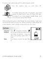
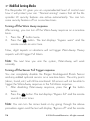
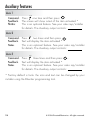
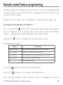
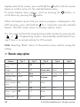
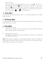
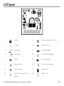
Responder LC Model 5901
Security and Remote Start
Owner’s Guide
© 2008 Directed Electronics, Vista, CA
G5702V 2008-08
Contents
Government regulations......................................................................................5
Warning! Safety first..........................................................................................7
What is included..............................................................................................10
Important information.......................................................................................10
Your warranty.........................................................................................10
Replacement remote controls.....................................................................11
Out of Range Notification.........................................................................11
System maintenance ...............................................................................11
Charging the Battery................................................................................12
Low battery indicator...............................................................................12
Battery Replacement.................................................................................13
Responder LC 2-Way........................................................................................14
LC 1-way companion........................................................................................15
Transmitter configuration...........................................................................15
Using the system..............................................................................................17
Additional arming features................................................................................23
Arm Features:..........................................................................................23
While the system is armed........................................................................23
System override.......................................................................................25
Modified Arming Modes..........................................................................26
Disarm Features:......................................................................................27
Additional remote start features.........................................................................28
Auxiliary features.............................................................................................34
Remote control feature programming..................................................................35
Sensor adjust..........................................................................................39
Pair Remote Mode...................................................................................39
Demo Modes..........................................................................................39
Safety features ................................................................................................40
Starter anti-grind circuitry..........................................................................40
Disabling the remote start system...............................................................40
Diagnostics.....................................................................................................41
Last trigger . ...........................................................................................41
Arming ..................................................................................................41
Disarming ..............................................................................................42
System status chirps ................................................................................42
Table of zones.........................................................................................43
Interpreting zone diagnostics.....................................................................43
Nuisance prevention® circuitry.................................................................44
Owner recognition ..........................................................................................45
Rapid resume logic...........................................................................................45
Power saver mode...........................................................................................46
System...................................................................................................46
2-way remote..........................................................................................46
Programming options........................................................................................47
Security & convenience expansions....................................................................49
Glossary of terms.............................................................................................51
LCD layout......................................................................................................53
Quick reference guide......................................................................................55
Limited lifetime consumer warranty.....................................................................57
Government regulations
This device complies with Part 15 of FCC rules. Operation is subject to the following two conditions: (1) This device may not cause harmful interference, and
(2) This device must accept any interference received, including interference that
may cause undesirable operation.
This equipment has been tested and found to comply with the limits for a class B
digital device, pursuant to Part 15 of the FCC Rules. These limits are designed to
provide reasonable protection against harmful interference in a residential installation. This equipment generates and can radiate radio frequency energy and,
if not installed and used in accordance with the instruction manual, may cause
harmful interference to radio communications. However, there is no guarantee
that interference will not occur in a particular installation. If this equipment does
cause harmful interference to radio or television, which can be determined by
turning the equipment OFF and ON, the user is encouraged to try to correct the
interference by one or more of the following measures:
• Reorient or relocate the receiving antenna.
• Increase the separation between the equipment and receiver.
• Connect the equipment into an outlet on a circuit different from that to which
the receiver is connected.
• Consult the dealer or an experienced radio / TV technician for help.
Remote Controls
To satisfy FCC RF exposure compliance requirements, this device should be used
in hand-held, hand operated configurations only. The device and its antenna
must maintain a separation distance of 20 cm or more from the person’s body,
except for the hand and wrists, to satisfy RF exposure compliance. This device
is designed to be used in a person’s hands and its operating configurations do
not support normal transmissions while it is carried in pockets or holsters next to
a person’s body.
© 2008 Directed Electronics. All rights reserved.
5
Control Center
To satisfy FCC RF exposure compliance requirements, the device and its antenna
must maintain a separation distance of 20 cm or more from the person’s body,
except for the hand and wrists, to satisfy RF exposure compliance.
This device complies with the Industry Canada Radio Standards Specification
RSS 210. Its use is authorized only on a no-interference, no-protection basis; in
other words, this device must not be used if it is determined that it causes harmful interference to services authorized by IC. In addition, the user of this device
must accept any radio interference that may be received, even if this interference
could affect the operation of the device.
WARNING! Changes or modifications not expressly approved by the party responsible for compliance could void the user’s authority to operate this device.
6
© 2008 Directed Electronics. All rights reserved.
Warning! Safety first
The following safety warnings must be observed at all times:
Due to the complexity of this system, installation of this product must only be
performed by an authorized Directed dealer.
When properly installed, this system can start the vehicle via a command signal
from the remote control transmitter. Therefore, never operate the system in an
enclosed area or partially enclosed area without ventilation (such as a garage).
When parking in an enclosed or partially enclosed area or when having the
vehicle serviced, the remote start system must be disabled using the installed
toggle switch. It is the user’s sole responsibility to properly handle and keep out
of reach from children all remote control transmitters to assure that the system
does not unintentionally remote start the vehicle. THE USER MUST INSTALL A
CARBON MONOXIDE DETECTOR IN OR ABOUT THE LIVING AREA ADJACENT TO THE VEHICLE. ALL DOORS LEADING FROM ADJACENT LIVING
AREAS TO THE ENCLOSED OR PARTIALLY ENCLOSED VEHICLE STORAGE
AREA MUST AT ALL TIMES REMAIN CLOSED. These precautions are the sole
responsibility of the user.
Remote starters on manual transmission vehicles operate differently than those
with automatic transmission because you must leave your car in neutral. You
must read this Owner’s Guide to familiarize yourself with the proper procedures
regarding manual transmission remote starters. If you have any questions, ask
your installer or contact Directed at 1-800-753-0600.
Before remote starting a manual transmission vehicle, be sure to:
• Leave the vehicle in neutral and be sure no one is standing in front or
behind the vehicle.
• Only remote start on a flat surface
• Have the parking brake fully engaged
© 2008 Directed Electronics. All rights reserved.
7
WARNING! It is the responsibility of the owner to ensure the parking/emergency brake properly functions. Failure to do so can result in personal injury or property damage. We recommend the owner have the parking / emergency brake
system inspected and adjusted by a qualified automotive shop biannually.
Use of this product in a manner contrary to its intended mode of operation may
result in property damage, personal injury, or death. (1) Never remotely start the
vehicle with the vehicle in gear, and (2) Never remotely start the vehicle with
the keys in the ignition. The user must also have the neutral safety feature of the
vehicle periodically checked, wherein the vehicle must not remotely start while
the car is in gear. This testing should be performed by an authorized Directed
dealer in accordance with the Safety Check outlined in the product installation
guide. If the vehicle starts in gear, cease remote start operation immediately and
consult with the authorized Directed dealer to fix the problem.
After the remote start module has been installed, contact your authorized dealer
to have him or her test the remote start module by performing the Safety Check
outlined in the product installation guide. If the vehicle starts when performing
the Neutral Safety Shutdown Circuit test, the remote start unit has not been
properly installed. The remote start module must be removed or the installer must
properly reinstall the remote start system so that the vehicle does not start in gear.
All installations must be performed by an authorized Directed dealer.
OPERATION OF THE REMOTE START MODULE IF THE VEHICLE STARTS IN
GEAR IS CONTRARY TO ITS INTENDED MODE OF OPERATION. OPERATING THE REMOTE START SYSTEM UNDER THESE CONDITIONS MAY RESULT
IN PROPERTY DAMAGE OR PERSONAL INJURY. YOU MUST IMMEDIATELY
CEASE THE USE OF THE UNIT AND SEEK THE ASSISTANCE OF AN AUTHORIZED Directed DEALER TO REPAIR OR DISCONNECT THE INSTALLED
REMOTE START MODULE. DIRECTED WILL NOT BE HELD RESPONSIBLE OR
PAY FOR INSTALLATION OR REINSTALLATION COSTS.
8
© 2008 Directed Electronics. All rights reserved.
This product is designed for fuel injected vehicles only. Use of this
product in a standard transmission vehicle must be in strict accordance
with this guide.
This product should not be installed in any convertible vehicles, soft or
hard top with a manual transmission. Installation in such vehicles may
pose certain risk.
© 2008 Directed Electronics. All rights reserved.
9
What is included
•
1 five-button, 2-way Supercode Responder LC remote control
(p/n 7752V)
•
•
•
•
•
•
•
•
1 five-button, 1-way Supercode remote control (p/n 7652V)
The control module with Stinger™DoubleGuard®two-stage shock
sensor
Control center with integrated status LED and Valet override
switch (P/N 6711T)
Revenger™Soft Chirp™six-tone siren
A remote start defeat toggle switch
Battery charger
Window decals
Your warranty registration
Important information
Congratulations on the purchase of your state-of-the-art remote start and
alarm system. Due to the complexity of this system, it must be installed
by an authorized dealer only. Installation of this product by anyone
other than an authorized dealer voids the warranty. All dealers are
provided with a preprinted dealer certificate to verify authorization.
By carefully reading this Owner’s Guide prior to using your system,
you will maximize the use of this system and its features. You can print
additional or replacement copies of this manual by accessing our web
site at www.directed.com.
➢ Your warranty
Your warranty registration must be completely filled out and returned
within 10 days of purchase. Your product warranty will not be validat10
© 2008 Directed Electronics. All rights reserved.
ed if your warranty registration is not returned. Make sure you receive
the warranty registration from your dealer. It is also necessary to keep
your proof of purchase, which reflects that the product was installed by
an authorized dealer.
➢ Replacement remote controls
Your system comes with one Responder LC remote control (P/N 7752V)
and one companion remote control (P/N 7652V). If additional remote
controls are desired, please see your authorized dealer or visit us at
www.directedstore.com to order.
➢ Out of Range Notification
If a command is issued from the remote, but the remote is beyond the
range of the vehicle to receive the command, the remote will respond
with an Out of Range notification. If this occurs, the remote will emit a
harsh tone and the out of range indicator will appear.
Since conditions will vary in different areas (ie: Weather, RF interference, etc) range may be affected and require you to be closer to the
vehicle for successful transmission.
➢ System maintenance
The system requires no specific maintenance. Your One way remote is
powered by small coin cell lightweight 3-volt lithium battery that will last
approximately one year under normal use. The 1-way remote uses one
CR2032 cell battery. The 2-way remote contains a non-replaceable
rechargeable battery. When the battery begins to weaken, the operating range will be reduced.
© 2008 Directed Electronics. All rights reserved.
11
➢ Charging the Battery
•
•
•
Plug in the USB charger (alternately a standard mini USB cable
connected to any standard USB port on any laptop or desktop
computer can also be used (cable not included).
The LCD displays “CHARGE” while the battery level bars within
the battery icon flash.
When charging is complete the LCD then displays “FULL”.
Note: If the battery has been severely discharged all remote functions
are disabled for a short charge period. The battery status outline flashes
and CHARGE is displayed on the LCD. Once the battery has accumulated enough charge for functionality, the LCD icons initialize with
a beep sound, the battery status outline stops flashing and the remote
becomes operational while still displaying CHARGE.
Warning! The temperature range over which the
battery can be charged is 0ºC TO 45ºC (32ºF
TO 113ºF). Charging the battery at temperatures
outside this range may cause severe damage to
the battery or reduce battery life expectancy.
➢ Low battery indicator
When the batteries are low on the 2-way remote it emits two groups of
beeps, the battery icon flashes and low battery is indicated, the alarm
then emits an additional chirp upon disarming of the alarm to let you
know its time to change the battery. When the battery is low on the
1-way remote, the remote responds the same way audibly.
Note: The Arm/Disarm chirps should be programmed ON for the
Bank and
alarm to emit any additional
chirpsTune
during
disarm. Channel
Ask your authorized
mode
present
and text
dealer if you have any indicator
questions.indicator
indicator
Sat mode,
bank selector
12
AM/FM
© 2008 Directed Electronics. All rights reserved.
11:53
RPT
DISP - MO
➢ Battery Replacement
Slide the door up to expose the battery beneath the holder. Remove the
ALLALL
expired battery. Place the new battery into the remote control. When
power is returned the remote control is ready for use.
➢ Multi-car control capability
ALLALL
You can operate the 2-way remote control system for two cars, with full
command capability for both vehicles.
To change the Car to be operated:
Two Way Remote
AUX
1. Press/hold the
button for 3 seconds or until the remote beeps.
The
or
icon flashes and the text “Car 1” or “Car 2” is
displayed.
2. Change car: While in this mode press the
button to switch
between cars and the
or
icon changes accordingly
indicating which car the remote currently operates.
3. Select the car you want to operate and then press any command
to operate the system. The selected car remains selected until the
setting is changed.
AUX
One Way Remote
AUX
1. Press and hold the
button until the amber light blinks once or
twice indicating current vehicle (one blink = car 1, two blinks =
car 2).
2. To change from one car to the other press the
button again.
3. When using the remote to control the system, the amber light will
flash in a sequence of 1 or 2 flashes indicating the current vehicle
selected.
AUX
© 2008 Directed Electronics. All rights reserved.
13
Responder LC 2-Way
4
1
5
5319
,&$
)&&,'(=6'(,
6
Feature
1
2
7
3
8
Description
LCD (2-way)
Activity/icon display
2
Lock button
Press for one second to arm.
3
Unlock button
Press for one second to disarm.
4
Auxiliary button
5
Remote start button
6
Function button
7
Charge Port (2-way)
The battery charger plugs into this port.
8
Label
Back of remote has label to identify the
remote.
9
Battery Door (1-way)
For accessing batteries when necessary.
10
Transmit LED (1-way)
Active when communicating
1
Press and hold for 1.5 second to activate
4
optional trunk
release.
5313
5 second ,&$
Press for one
to activate remote
)&&,'(=6'(,
start.
6
2
3
Allows access
to programming and modi7
fies operation of the other buttons.
8
AUX
Note: If the keypad is locked, first press
and then press
to exit.
AUX
14
© 2008 Directed Electronics. All rights reserved.
LC 1-way companion
8
10
2
9
3
5
4
AUX
6
Note: See call-out table for 2 way on previous page.
➢ Transmitter configuration
AUX
Level10
Direct Access
x1
Button
Arm/Lock
Silent Arm
(Panic)
Disarm/Unlock
AUX
x2
2
3
5
4
Silent Disarm6
AUX
Sensor
AUX
x3
Bypass
Valet
Silent Mode
Silent Mode
Sensors
Car Finder
x4
8
531;
,&$
)&&,'(=6'(,
%$77(5<&5
All Zones
9
On/Off
Remote Start
Reset
Timer Mode
Smart Start
Defogger
AUX
On/Off
Runtime
On/Off
On/Off
On
AUX
AAUUXX
Trunk Release
AUX 1
AUX 2
AUX 3
Advance Level
Temperature
Runtime
Event His-
Change Car
Check *
Remaining *
tory Report*
AUX
(3s), Enter
programming
(8s) *
AUX
*
button must be pressed and held to access state, for example to
© 2008 Directed Electronics. All rights reserved.
15
AUX
access “Request temperature” or “Runtime remaining” press the
ton the specified amount of times, and then hold.
but-
Note: Pressing more than one button simultaneously generates an Error
tone.
16
© 2008 Directed Electronics. All rights reserved.
Using the system
Please note the screen shot to the right of a feature indicates what the
display looks like when this feature is activated.
Arm
Command: Press one time to Arm
Feedback: Lock Icon will appear, and one beep
from remote
Notes: Press/hold for 1.5 seconds to Arm
the system and then activate the
Panic output
AUX
Details: The siren in the vehicle will “chirp” once and the parking lights
will flash once. If the power door locks have been connected, the
doors will lock. The system will automatically check for errors when it
arms. The 2-way remote will “chirp” once and the lock icon appear to
confirm arming. If no arm confirmation is received, the remote will give
the Out-Of-Range signal.
If errors are found when arming:
If an alarm trigger zone – such as a door, the trunk, the hood, or a
sensor, was active at the time of arming, the system will “bypass”, or
ignore, this trigger zone. This allows the system to continue to protect
your vehicle using the remaining trigger zones.
You are notified of this active zone immediately after arming the system.
The siren in the vehicle will “chirp” again after arming. The Status LED
indicator in the vehicle will blink in a pattern to indicate the active
zone number error which was found (See Table of Zones). The 2-way
remote control will sound a short “error” tone and the text will display
the active zone..
© 2008 Directed Electronics. All rights reserved.
17
Disarm
Command: Press one time to Disarm
Feedback: Unlock icon appears and remote beeps
AUX
twice
The siren in the vehicle will “chirp” twice, and the
parking lights will flash. The 2-way remote will
“chirp” twice and the
unlock icon appears to
confirm disarming. The door locks (if connected) will unlock and the
parking lights will flash
AUX
Note: For additional chirps when disarming the system refer to the
diagnostics section of this guide
Remote Start
Command: Press one time to activate Remote
Start
Feedback: Remote Start Icon appears on screen.
remote emits a tone and parking
lights flash
AUX
Notes:
Before using the remote start be sure the vehicle is parked in a safe
area with proper ventilation.
The preset remote start run time is 12 minutes. This can be changed to
between 12 and 60 minutes.
The system has a feature, if programmed On , that automatically notifies you when the runtime is running low. When the system reaches 3
18
© 2008 Directed Electronics. All rights reserved.
minutes and 1 minute of runtime remaining, it sends the 2-way remote
control a paging signal.
Points to remember:
If the hood is open or if the brake pedal is pressed, the vehicle will not
remote start. The remote start shuts down:
•
•
•
•
When the brake pedal is pressed.
The hood is opened.
When the remote start command is sent again from a remote
control.
When the runtime expires.
To drive your vehicle after it has been remote started:
1. Get in without stepping on the brake.
2. Insert the ignition key and turn it to the ON position.
3. Now, step on the brake.
The remote control will play the remote start shutdown tone. You have
now taken direct control from the remote start system.
Valet Take-Over
The Valet Take-Over feature allows the vehicle to remain running after
the key has been removed from the ignition. This feature is useful for
occasions when you wish to exit and lock the vehicle for short periods
of time, but would like to leave the motor running and the climate
controls on.
To enable Valet take-over; while the vehicle is running, press
1 time
and the parking lights will flash after a couple of seconds turn off the
ignition and the car should stay running. Once you exit the vehicle you
can lock the system and the car will remain running. If the vehicle shuts
down, then the unit did not enter valet take-over mode.
AUX
© 2008 Directed Electronics. All rights reserved.
19
AUX
Aux
Command: Press and hold for 1.5 seconds to
activate the Trunk Release.
Feedback: The trunk icon appears and the remote plays a short tone.
Notes: This is an optional feature. See your
sales rep/installer for details. The
factory default icon and text is trunk.
The icon and text can be changed by your installer using
the Bitwriter programming tool.
AUX
Function shift
Command: Press 1 to 4 times. (See Transmitter configuration table)
Feedback: Display shows a text message across the bottom for the
command received.
Notes: Each Press then release, shifts the function of the command button.
Valet mode
AUX
Command: Press
two-times and then
.
Feedback: Unlock Icon appears hollow and
text states Valet when entering Valet
mode. Notes: Even if armed the remote beeps one
time and the doors remain locked.
When exiting Valet mode the Unlock
Icon appears solid, the text states Valet and the remote
beeps two-times. The security system is disarmed but the
doors are still locked.
AUX
20
© 2008 Directed Electronics. All rights reserved.
REVISIONS
DESCRIPTION
REV.
1
DRN.
DATE
To enter or exit valet mode with the valet/program switch:
Turn
the
ignition
key
on
and
then
off.
10.44
36.32
At anytime during the next 10 seconds, press and
release the Valet switch. Now the Status LED lights
constantly if you have entered Valet® Mode, and
shuts off when exiting Valet Mode.
11.50
CASE P/N:IADGH0A1
KEY P/N:IKDEL0A0
%2'<0$7(5,$/+,+($7$%689
C
±
0.30
0.40
0.80
2.00
When locking the system in Valet Mode,NUTEK
the screen displays “valet” and
the remote then emits an error tone. When unlocking in Valet Mode, the
screen displays “valet” and the remote emits two error tones.
1. Texture is same as
2. Radious will be if not specified.
3. Body color :
%/$&.
SCALE:
1:1
UNIT:
MATERIAL
M/M
DRN BY
VICTOR
DATE
TITLE
DEI
OLED IVU
YGF
CODE
CORPORATION
11/20/07
CHK BY
FELIX
APPD BY
FINISH
SIZE
SHEET
OF
A4
DEPT
DRAWING NO
94I0600
REV
0
94I0600
Car finder
AUX
Command: Press
three-times and then
.
Feedback: Icon of vehicle flashes and text reads
car finder. On Vehicle: 1 long siren
chirp and parking lights flash 10
times.
Notes: Arm/Disarm cancels the light flashes.
AUX
© 2008 Directed Electronics. All rights reserved.
21
Cabin temperature
Command: Press and release
one time, then
Hold for 1.5 seconds.
Feedback: Screen will display current in cabin
temperature.
Notes: Cabin temperature is displayed on
the remote.
22
AUX
© 2008 Directed Electronics. All rights reserved.
Additional arming features
➢ Arm Features:
Silent arm
AUX
Command: Press
one- time and then press
Feedback: Screen changes to the lock icon
Notes: Arms the system without chirps
AUX
The system arms without the confirmation chirp. The parking lights
will flash once. The 2-way remote will not “chirp” and the lock icon
will appear to confirm arming. If no arm confirmation is received, the
2-way remote will give the Out Of Range signal.
➢ While the system is armed
• Fail-Safe Starter Kill
The starter is disabled by the system’s Fail-Safe starter kill.
Alarm Responses
The security system can generate two levels of alarm: Warn Away - Soft
siren chirps and flashing parking lights.
The purpose of Warn-Away is to warn a would-be thief next to your
vehicle that the vehicle is protected, but in a manner that does not call
attention to it from more than a few feet away.
Full Alarm Trigger
Sounds the siren at maximum volume and flashes the parking lights.
The default duration of the Full Alarm is 30 seconds. This can be programmed to any duration from 30 to 60 seconds manually. Ask your
authorized dealer for details.
© 2008 Directed Electronics. All rights reserved.
23
Warn-Away response is triggered by:
• Lesser or lighter vibrations or impacts (detected by the Stinger Doubleguard shock sensor)
• An optional Proximity Sensor (508D) triggered in the outer zone
Full Alarm response is triggered by:
•
Heavier impact to the vehicle (detected by the Stinger DoubleGuard shock sensor).
• Opening the trunk or hood.
• Opening a door: the Progressive Door Trigger feature will first
sound the Warn-Away response, followed immediately by Full
Alarm.
• An optional sensor, such as an optional Proximity Sensor triggered
in the inner zone.
Any attempt to start the car: the Progressive Ignition Trigger will first
sound the Warn Away response, followed immediately by Full Alarm.
Paging Signals
If the Full Alarm response is triggered, the 2-way remote control will be
sent a paging signal by the in-car system.
Note: Paging range varies with terrain and environmental conditions.
While the alarm is triggering:
Press the
button on the remote. The siren will stop sounding and
disarm the alarm system.
AUX
High-Security Disarming
If you want the Full Alarm response to stop without unlocking the doors,
press the
button. The system will re-arm and the current alarm re24
AUX
© 2008 Directed Electronics. All rights reserved.
sponse will reset.
REVISIONS
DESCRIPTION
REV.
1
DRN.
DATE
➢ System override
To disarm the system without a remote control:
You will need to use your Override Switch located on your systems
control center (see diagram below) to disarm the system. The Override
Switch disarms the system only if you have the vehicle key.
36.32
10.44
11.50
To check proper operation:
CASE P/N:IADGH0A1
KEY P/N:IKDEL0A0
• Open the door. The alarm will sound.
NUTEK
Immediately insert the key into the ignition and turn it to the RUN or ON
position. (all the indicators in the dash will turn on).
Press the Override Switch once,
the alarm should shut off and now the
94I0600
vehicle should start with the key.
%2'<0$7(5,$/+,+($7$%689
*Tolerance please refer specification
of tolerance limits "c"
INJECT TOLERANCE SPEC.
GRADE
A
±
B
C
±
±
UNDER 6
0.08
0.16
0.30
6~30
0.10
0.20
0.40
30~120
0.20
0.40
0.80
120~300
0.40
0.80
2.00
DIMENSION
1. Texture is same as
2. Radious will be if not specified.
3. Body color :
%/$&.
SCALE:
1:1
MATERIAL
FINISH
CODE
UNIT:
M/M
DRN BY
VICTOR
DATE
TITLE
DEI
OLED IVU
APPD BY
SHEET
CORPORATION
11/20/07
CHK BY
FELIX
YGF
SIZE
OF
A4
DEPT
DRAWING NO
94I0600
Note: The Override Switch feature allows you to select a specific
number of presses needed to disarm the alarm. If the Override
Switch has been programmed to a new number of presses by your
authorized dealer, that number should be indicated below.
Override Switch Number ___________
© 2008 Directed Electronics. All rights reserved.
25
REV
0
➢ Modified Arming Modes
The Responder LC gives you an unprecedented level of control over
how it will protect your car. “Normal arming” means that all the Responder LC security features are active automatically. You can turn
some security features off on a one-time basis.
Turning off the Warn Away response
After arming, you can turn off the Warn-Away response on a one-time
basis.
1. Press the
button twice.
2. Press the
button. The text displays “bypass warn” and the
remote sounds an error tone.
AUX
AUX
Now, slight impacts or vibrations will not trigger Warn-Away. Heavy
impacts will still trigger Full Alarm.
Note: The next time you arm the system, Warn-Away will work
normally.
Turning off the Sensor Full Trigger response
You can completely disable the Stinger Doubleguard Shock Sensor
and any added optional sensors on a one-time basis. The entry points
(doors, hood, etc.) will still be monitored. All sensors will not be able to
trigger the Warn-Away response or the Full Alarm response.
1. After disabling Warn-away response, press the
the button
twice.
2. Press the
button. The text displays “Bypass full” and the remote
sounds 2 error tones
AUX
AUX
Note: You can turn the zones back on by going through the above
procedure again and the text will display “Bypass off” and the remote
26
© 2008 Directed Electronics. All rights reserved.
will beep once.
Silent Mode 2 - Turning off the siren
You can turn off the vehicle siren and flashing lights on a one-time basis,
leaving the system’s paging feature as the only alarm response.
Note: Call the police immediately if you witness a crime in progress.
Paging range varies with terrain and environmental conditions.
Sensor Silent Mode
In this mode, a sensor cannot trigger the siren, but will cause the
2- way remote to be paged. All entry points (doors, hood, etc.) will still
trigger the siren.
AUX
Press the
button three times, and then press the
button. The text
will display “sensor silent arm” confirming entry into sensor silent mode.
Note: The next time you arm the system, it will function normally.
AUX
Full Silent Mode.
In this mode, the siren cannot be triggered, but any trigger will cause
the 2-way remote to be paged.
Press the
button four times, and then press the
within five seconds. The text will display “ full silent arm” confirming entry into full
silent mode
AUX
AUX
➢ Disarm Features:
Silent disarm
AUX
Command: Press
one- time and then press
Feedback: Screen changes to unlock icon
Notes: Disarms the system without chirps
© 2008 Directed Electronics. All rights reserved.
.
AUX
27
Additional remote start features
Manual Transmission
If the vehicle has a manual transmission the proper steps must be followed before leaving the parked vehicle or the remote start feature is
disabled.
1. Make sure the engine is running and the doors on the vehicle are
closed.
2. Put the transmission in neutral.
3. Press on the brake in the vehicle.
4. Apply the emergency brake.
5. Release the brake.
Note: Pressing the brake pedal again after this step will disable the
remote start feature.
6. Within 15 seconds activate the remote start from the remote.
7. The parking lights flash 5-times confirming that the remote start is
active. If the parking lights do not flash 5-times, then repeat steps
1 - 6.
8. Turn off the ignition (the car stays running when key is turned off).
9. Exit the vehicle.
10. Arm the alarm (the vehicle should shut off when arming the system).
You can now remote start the vehicle. If a door is opened or the alarm
is triggered before the next remote start activation the system will not
remote start.
Note: To enable Valet take-over with a manual transmission, open the
door and enter into manual transmission mode, as described above.
The parking lights flash one-time when entering Valet take-over. Once
you exit the vehicle you can lock the system and the car will remain
28
© 2008 Directed Electronics. All rights reserved.
running. If the vehicle shuts down when locking, then the unit did not
enter valet take-over mode.
Timer mode
AUX
Command: Press
two-times and then
.
Feedback: Small timer icon appears and text reads “timer start on”.
The vehicle will confirm with 4 fast parking light flashes.
Notes: Enables or disables the remote start timer mode.
AUX
The system must be armed for the timer mode to operate. The system
will start every 3 hours for a maximum of six cycles until canceled by the
brake, hood, or neutral safety shut-down wires. The remote will respond
with the Start and Stop remote start notification during each Start and
Stop of the Vehicle while in Timer mode.
Important: Use Timer Mode in open areas only. Never start
and run the vehicle in an enclosed space such as a garage
or carport.
To activate timer mode with a manual transmission:
1. Enter the MTS mode.
2. Exit the vehicle and arm the alarm.
3. Enter the timer mode. The parking lights quickly flash 4 times to confirm
entry into timer mode (vehicle does not remote start at this point). Vehicle
begins the timer mode sequence.
To exit timer mode with transmitter:
twice and then press
• Press
confirming timer mode is exited.
AUX
. Parking lights flash slowly four times
AUX
To exit timer mode without transmitter:
1. Make sure the remote start system is not operating the engine.
© 2008 Directed Electronics. All rights reserved.
29
2.
Turn the ignition on. Timer Mode is exited and the parking lights flash
slowly four times.
Note: The Bitwriter can change the amount of times the remote start activates
and, it can change the intervals between activations in timer mode.
Turbo Timer mode
Short run turbo mode keeps the engine running after arriving at your
destination for a programmable period of 1, 3, 5 or 10 minutes. This
allows the system’s timer to conveniently cool down the turbo after you
have left the vehicle.
To activate Turbo Timer Mode with an automatic transmission:
1. Make sure the Turbo timer feature is turned on in the features
grid.
2. Open the vehicle door.
3. While the vehicle is running; press the
button twice followed
by the
button.
4. The parking lights flash once and the remote plays the remote start
activation tone confirming that the remote start is activated (the one
way remote only flashes the parking lights).
5. Turn off the ignition (car stays running).
6. Exit the vehicle and arm the system.
7. At this point the vehicle stays running for the programmed runtime.
AUX
AUX
To activate turbo timer mode with a manual transmission:
1. Enter MTS mode with the door open.
2. Transmit the timer mode feature with the remote by pressing twotimes, and then
.
3. After exiting the vehicle, lock the system and the vehicle remains
running for the programmed runtime. (The remote start feature is
AUX
AUX
30
© 2008 Directed Electronics. All rights reserved.
still enabled).
You can still remote start the vehicle after the turbo timer has timed out
and shut off the vehicle. For safety reasons, if a door is opened or if the
alarm is triggered while you are away, the remote start exits the manual
transmission mode and does not remote start until the MTS sequence
is re-initiated.
Note: An optional push button can be hard wired to the (-) activation
input (H1/10) on the remote start. This allows the user to activate the
turbo timer without having to use the remote.
When the vehicle is running follow the procedures listed above, but
instead of pressing the remote, press the push button the appropriate
number of times to activate the remote start (factory setting is for 1
pulse). The remote emits the remote start confirmation tone, after which
you can turn off the ignition and exit the vehicle. The car remains running for the pre-programmed amount of time.
Runtime check
AUX
Command: While the remote start is running, press
two-times,
and then Hold for 1.5 seconds.
Feedback: Text reads runtime and displays time left
Notes: This feature is only available on the 2way remote.
Runtime reset
AUX
Command: While the remote start is running, press
one-time and
then
.
Feedback: Remote start ON tones.
Notes: Re-starts the remote start runtime counter if remote start
is active. Note: If remote start is not active, the 2-WAY
AUX
© 2008 Directed Electronics. All rights reserved.
31
remote will respond with error tone.
Rear defogger
AUX
AUX
Command: Press
four times, and then
. (Only after remote
start is on.)
Feedback: Defogger icon appears on remote and text reads Defrost
On.
Notes: While the remote start is running the defroster will manually be turned on for one remote start cycle. When the
remote start shuts down, the defroster will work normally.
The defroster turns on when the temperature inside the
vehicle is 55 degrees or below when this feature is
wired and enabled.
Smart start
AUX
AUX
Command: Press
three-times and then press
.
Feedback: The vehicles parking light flash 5 times fast and the text
on the 2way remote reads Smart Start On
Notes: Enables or disables the SmartStart feature. The smart
start feature of this system will allow you to have the
remote start activate when the vehicle reaches a certain
temperature (hot or cold) or a certain voltage. The factory setting for temperature high is 100 °F the setting for
low is 0 °F. The voltage setting is for 10.5V.
These settings can be adjusted or turned off by your
installer when using the Bitwriter.
To activate the Smart Start Mode with a manual transmission:
1. Enter the MTS procedure.
2. Exit the vehicle and press the
button on the remote (the vehicle
AUX
32
© 2008 Directed Electronics. All rights reserved.
will shut down when locking).
3. Press the
button on the remote 3 times and then press the
button.
AUX
AUX
4. The 2 way remote will beep once and flash the
LED once.
5. The parking lights on the vehicle will flash 5 times fast confirming
entry into smart start mode
6. The vehicle will now remote start when the cabin temperature
reaches the programmed thresholds or when the vehicle battery
reaches the programmed voltage.
AUX
The Smart Start Mode can be exited by following the activation procedure with the remote or can be deactivated manually by turning on the
ignition or pressing the brake pedal in the vehicle. The parking lights
will flash 5 times slow confirming that Smart Start Mode is exited.
Details: Smart start uses temperature and voltage settings to determine
when the vehicle should start and run. If any changes to temperature
or voltage are made using the Bitwriter programming tool Smart start
activation is affected.
The Smart Start function works similar to the Timer mode. The system
must be in the locked mode, and using the system default settings, it
has a maximum of 6 starting cycles and checks the voltage/cabin
temperature every 3 hours to see if the thresholds have been met.
If thresholds have been met then the remote start will start the vehicle
and run for the pre programmed time. It counts the first start as one successful start, leaving 5 start cycles.
If the threshold has not been met then the system will not start the vehicle, and 6 start cycles are left. The unit continues to check threshold
levels every 3 hours.
© 2008 Directed Electronics. All rights reserved.
33
Auxiliary features
Aux 1
AUX
Command: Press
one time and then press
.
Feedback: The screen will show a text of the item activated *
Notes: This is an optional feature. See your sales rep/installer
for details. The Auxiliary output controls:
AUX
Aux 2
AUX
Command: Press
two times and then press
.
Feedback: Text will display the item activated *
Notes: This is an optional feature. See your sales rep/installer
for details. The Auxiliary output controls:
AUX
Aux 3
AUX
Command: Press
three times and then press
.
Feedback: Text will display the item activated *
Notes: This is an optional feature. See your sales rep/installer
for details. The Auxiliary output controls:
AUX
* Factory default is trunk. the icon and text can be changed by your
installer using the Bitwriter programming tool.
34
© 2008 Directed Electronics. All rights reserved.
Remote control feature programming
The Responder LC 2-way remote control has menus for configuring the
remote control user features and for programming the remote to the
system control module.
Before you start make sure the keypad is unlocked. (See page 14)
To program the remote user features:
AUX
Press and hold the button on the remote for about 8 seconds. (ignore
the car indicator at 3 seconds). The status screen clears and “Main
Menu” is displayed in the text display area of the screen.
AUX
Release the
button to display the remote options menu.
Remote options menu
Options
Description
Remote Setup
Allows feature programming of the remote
Sensor Adjust
Adjusts the onboard impact sensor
Pair Remote
Sets up remote for programming to the system
Demo mode
Places remote in demo mode
Exit
Exits programming
Press the
Press the
AUX
button to scroll up the Main Menu.
button to scroll down the Main Menu.
AUX
From the Main Menu, once a feature name is displayed in the text
© 2008 Directed Electronics. All rights reserved.
35
AUX
display area of the screen, press and hold the button until the remote
beeps to confirm entry into the selected feature menu.
To access feature menu options, scroll up pressing the
button, or
scroll down by pressing the
button.
AUX
AUX
When the feature option that you want to program is displayed in the
LCD text area, press and hold the for 1 second to save the selected
feature. The LCD screen returns to previous options menu.
AUX
You can save and exit the programming mode anytime by pressing the
or
. Programming mode is automatically exited without saving if there is no remote activity for 30 seconds.
Note: Selecting “Back” returns to the previous menu without saving the
setting.
AUX
AUX
➢ Remote setup options
Feature
Opt 1
Opt 2
Opt 3
Auto keypad
lock
On
Off
Back
Page
On
Off
Power save
Opt 4
Back
Page alert
Vibe
Tone
Both
Screen only
Remote start
display
Clock
Temp
Runtime
Back
Low runtime
alert
On
Off
Back
Car 2
On
Off
Home
Back light
color
Off
1-7
Back
Temp units
F°
C°
Back
36
Opt 5
Back
Back
© 2008 Directed Electronics. All rights reserved.
Feature
Opt 1
Opt 2
Opt 3
Button press
beep
On
Off
back
System type
Remote start
& Security
Remote start
Back
Clock set
Clock time
Back
Opt 4
Opt 5
➢ Menu option descriptions
•
Auto keypad lock
Automatically locks the remote buttons when the buttons are not used for
60 seconds. Prevents “accidental” presses of the remote.
Press
then
to unlock the keypad.
AUX
Note: If the auto keypad lock feature is programmed On, the remote automatically unlocks when the vehicle ignition is turned Off. The remote stays
unlocked to allow time to exit and unload the vehicle, and then lock the
AUX
button is pressed, the keypad auto
doors with the remote.
When the
lock feature resumes normally.
•
Page On or Off and Power save
When paging is “On” the remote checks the status of the system every
four seconds, and reports any alarm triggers (if the system is within the
AUX
operating range).
In the paging “Off” setting, the remote does not check the status of the
system. In the paging Off mode the remote will only beep and report when
a button on the remote is pressed.
In the “battery saver” mode, the remote goes into sleep mode if no buttons
are pushed for 72 hours. The timer resets each time a button is pressed.
•
Page Alert / Vibe/Beep Tone/Both or /Screen only
Receive command confirmations on the remote with vibrations, beeps or
both, or with display only.
© 2008 Directed Electronics. All rights reserved.
37
•
Remote start display: Clock, temperature or runtime
Allows you to choose what is displayed in the text during the remote start
sequence. Clock displays the current time during remote start.
Temperature displays the current cabin temperature during the remote start.
Runtime displays the runtime remaining during the remote start.
•
Low Runtime Alert
The remote reports with one short beep followed by 1 short error tone
(repeated twice) and the text area displays “run time” when the remote
start runtime is at the 3-minutes remaining and one more time at 1 minute
remaining. You have the option to let the remote start timeout or use the
“runtime reset” feature . When programmed “Off” you will not receive a
low runtime alert on the remote.
•
Car 2 On or Off/Home
Turns Off or On, 2 car operation from the remote. The option for “home”
is not available.
•
Backlight Color Off/1 - 8
Turn Off the LCD backlighting or changes the color of the backlighting.
Color options include: Blue, green, red, aqua, purple, lime, clear
•
Temperature Units F and C
Display temperature in Fahrenheit or Celsius
•
Button Press Beep On or Off
Turn Off beeps when a button on the remote is pressed
•
System Type Remote Start & Security or Remote Start
Select the type of system you are using, security system with remote start
or a keyless entry system with remote start (to ensure that the correct icons
are displayed on the LCD)
•
Clock Set
To enter clock set mode, Press the
button. The LC text display reads
“hour” to confirm entry in the clock set menu.
AUX
Press the
38
AUX
button to move up the menu, press the
button to move
AUX
© 2008 Directed Electronics. All rights reserved.
AUX
down the menu.
After you select the time increment (hour /min ), press . The hour or
minute flashes. Press the
button to move up to the hour or minute, and
press the
button to move down to the hour or minute you want to set.
Once the desired time has been reached you can either choose “back” in
the menu or press
or
to save and exit.
AUX
AUX
➢ Sensor adjust
Used to adjust the onboard impact sensor, it is recommended that your installer
adjust the sensor.
AUX
➢ Pair Remote Mode
AUX
It is recommended that this feature for programming the remote to the system is
performed by your installer.
➢ Demo Modes
•
One-time with sound
The LCD icons display one at a time with icon name displayed in the text
field, while the remote is playing tones.
•
One-time without sound
The LCD icons display one at a time until they are all turned on. The remote
does not play any tones.
Note: If the charger is plugged into the remote and demo mode is activated, the
remote plays the demo mode continuously. The continuous loop demo mode is
exited when the charger is disconnected.
© 2008 Directed Electronics. All rights reserved.
39
Safety features
This system has several important safety features to ensure proper operation of the motor and prevent accidental damage to the engine or
its components.
➢ Starter anti-grind circuitry
Whenever the vehicle is remote started, advanced anti-grind circuitry
prevents the starter from engaging, even if the key is turned to the start
position. This prevents damage to the starter motor if the key is turned
to the start position during remote start operation.
Note: Anti-grind circuitry only works when the remote start system is
operating the motor and the Failsafe® Starter Kill relay is installed.
➢ Disabling the remote start system
This feature allows the remote start unit to be temporarily disabled to
prevent the vehicle from being remote started accidentally. This feature
is useful when the vehicle is being serviced or stored in an enclosed
area.
To disable the remote start, move the shutdown toggle switch to the OFF
position. Check with your installer for the location.
Location of Shutdown Switch____________________________
40
© 2008 Directed Electronics. All rights reserved.
Diagnostics
The microprocessor at the heart of your system is constantly monitoring
all of the switches and sensors connected to it. It is designed to detect
any faulty switches and sensors and prevent them from disabling the
entire system. The microprocessor will also record and report any triggers that occurred during your absence.
Refer to System Status Chirps and Table of Zones sections of this guide
for diagnostic information.
➢ Last trigger
AUX
Press
three times and then hold for 1.5 seconds. The display scrolls
last trigger and the remote recalls the last zone that has triggered the
security system.
➢ Arming
If the security system is armed at the same time that an input is active
(such as a door opening or sensor triggering), you will hear one siren
chirp to indicate arming and a second siren chirp to indicate Bypass
Notification.
A Bypass Notification chirp means that the security system ignores
the input that was active when the system was armed, until that input
ceases. Three seconds after that input ceases, the security system will
resume normal monitoring.
For example: if your vehicle has an interior light exit delay and you arm
your security system before the interior light turns off, you may hear a
second Bypass Notification chirp.
Once the light turns off, the security system resumes normal monitoring.
© 2008 Directed Electronics. All rights reserved.
41
Note: Bypass Notification does not occur when the system is in Silent
Mode or if the notification chirps have been programmed off by the
installer.
➢ Disarming
Extra chirps heard when disarming the system are the Tamper Alert.
If four chirps are heard when disarming the system, then the security
system was triggered in your absence.
If five chirps are heard when disarming the system, the system was
triggered so many times that the Nuisance Protection® Circuitry has
bypassed the intended zone. In either case, the status LED will indicate
which zone was involved (see Table of Zones).
The security system will retain this information in its memory, and chirp
four or five times each time it is disarmed, until the next time that the
ignition is turned on.
Note concerning low battery alert: When the batteries in the remote
are low the alarm will give an additional chirp when disarming to let
you know its time to change the battery in the remote.
➢ System status chirps
The siren will chirp when arming/disarming the system. The pattern of
chirps will audibly report the system’s status as described below.
Action
Number of Chirps
Description
Arm
1
System armed
Arm
1 (3-second delay) + 1
System armed with bypass notification
Disarm
2
System disarmed
42
© 2008 Directed Electronics. All rights reserved.
Disarm
3
disarmed with Low battery indicator
Disarm
4
System disarmed with Tamper Alert
Disarm
5
System disarmed with NPC active.
➢ Table of zones
A zone is represented by the number of LED flashes used by the system
to identify a particular type of input. Standard input assignments are
listed in the following table, along with spaces to write in any optional
sensors or switches that have been installed.
Zone
Description
1
Trunk Pin
2
Instant trigger: a heavier impact
detected by the onboard shock
sensor
3
Door switch trigger
4
Instant trigger: For optional
sensors
5
Ignition trigger
6
Hood Pin
Dealer installed options
➢ Interpreting zone diagnostics
Warn Away responses are not reported by arming or disarming diagnostics. If you receive a Bypass notification when arming or a Tamper
Alert notification when disarming, look at the LED on the control center.
Active or triggered zones will be indicated by a pattern of blinks by
the LED.
© 2008 Directed Electronics. All rights reserved.
43
For example: If zone 3 was active or triggered, the LED will blink three
times with a two-second pause. Then it will blink three times again, and
repeat until the ignition is turned on.
➢ Nuisance prevention® circuitry
Your system has Directed’s Nuisance Prevention® Circuitry (NPC). It
prevents annoying repetitive trigger sequences due to faulty door pin
switches or environmental conditions such as thunder, jackhammers,
airport noise, etc.
For example: If the alarm triggers three times within a 60-minute period
and each time the same sensor or switch triggers the alarm, NPC will
interpret those triggers as false alarms. After the third trigger, NPC ignores, or bypasses, that sensor or switch (along with any other sensors
or switches sharing the same zone) for 60 minutes.
If the bypassed sensor tries to trigger the security system while it is being
bypassed, the 60-minute bypass period will start over. This ensures that
a sensor that is continually being triggered will remain bypassed.
The vehicle doors are protected by NPC differently. If your security
system is triggered by an open door for three full cycles, the system will
bypass the doors until the trigger ceases.
➢ Remote Start
This system can provide you with information to indicate what the problem is
when using the remote start. When the remote start is activated and fails to
engage, count the parking light flashes to determine the problem. The parking
lights will flash between 5 - 8 times to indicate what caused the no start situation.
•
5 flashes: brake wire is active
•
6 flashes: hood pin is active
44
© 2008 Directed Electronics. All rights reserved.
•
7 flashes: manual transmission mode is enabled and not initialized
•
8 flashes: neutral safety wire has no ground or the remote start
defeat toggle switch is off.
Keep a record of the number of flashes, to assist your installer when taking the
vehicle in for service.
Owner recognition
Owner Recognition lets up to four users of the system have unique settings that meet their specific needs. It is almost like having four separate
alarms in your vehicle, one for each user. This feature is only available
to authorized dealers using the Bitwriter or Bitwriter 2 program tool.
Rapid resume logic
This Directed system will store its current state to non-volatile memory.
If power is lost and then reconnected the system will recall the stored
state from memory.
For example, if the unit is in Valet Mode and the battery is disconnected
for any reason, such as servicing the car, when the battery is reconnected the unit will still be in Valet Mode. This applies to all states of the
system including arm, disarm, and Valet Mode.
© 2008 Directed Electronics. All rights reserved.
45
Power saver mode
➢ System
Your system will automatically enter Power Saver Mode while armed or
in Valet Mode, after a period of time in which no operation has been
performed. This lowers the current draw on the vehicle’s battery. Power
Saver Mode takes over under the following conditions:
Power Saver when the system is armed: After the system has been
armed for 24 hours the LED will flash at half its normal rate, decreasing
the system’s current draw.
Power Saver in Valet Mode: When the system enters Valet Mode the
Status LED on the Responder LE control center illuminates steadily. If the
vehicle is not used (ignition is not turned on) for a one hour period while
the system is in Valet Mode, the status LED will shut off. If the system
remains in Valet Mode, the LED will come back on the next time the
ignition is turned on and then back off.
➢ 2-way remote
Your Responder LC 2way remote control has a feature called remote
power save mode. When programmed ON under remote options, the
remote will conserve power by disabling the paging function if unused
for more than 72 hours. Pressing any button on the remote will restore
the paging function.
The default setting is ON. See Remote control programming section of
this guide or ask your dealer for details on how to program.
46
© 2008 Directed Electronics. All rights reserved.
Programming options
Your system has many custom programmable options. Some may require installation labor. Ask your authorized dealer for details.
The following is a list of the programmable options, with the factory
settings in Bold.
•
Active arming (remote only) passive arming with or without locking
the doors (automatic arming without locking the doors 30 seconds
after the last door has been closed), or Auto Re-arm with or without
locking the doors (Automatically arms 60 seconds after disarm if
no door is opened).
•
Arming/disarming siren chirps ON with or without Warn-away
chirps, Or OFF with or without Warn-away chirps.
•
Ignition controlled door lock feature ON or OFF: When this feature is programmed on, the doors will lock three seconds after the
ignition is turned on, and unlock when the ignition is turned off.
If your installer is programming the security system with the Directed
Bitwriter®, ignition lock and unlock are independent features that can
be programmed separately.
•
Panic mode enabled/disabled when the ignition is turned on or
completely turned OFF. (Some states have laws against sirens
sounding in moving cars.)
•
Full trigger response 30 or 60 seconds: This determines how long
the full triggered sequence lasts. Some states have laws regulating
© 2008 Directed Electronics. All rights reserved.
47
how long a security system can sound before it is considered a
nuisance.
If your installer is programming the security system with the Directed
Bitwriter®, the full triggered response can be programmed for any
duration ranging from 1 to 180 seconds.
•
Siren tones and chirp volume: The output of the Revenger™Soft
Chirp™ siren consists of six different tones in sequence. Any of
these tones can be eliminated by a dealer, resulting in a unique,
easily identifiable siren sound. The arm/disarm chirps can be either full volume or 6 decibels quieter than the full alarm blast.
•
Comfort closure is a programming option which closes the vehicle’s windows after remote locking.
Note: Comfort closure can only be used on cars that have the capability of closing the windows (and on some cars the sunroof as well) with
the key cylinder in the door.
48
© 2008 Directed Electronics. All rights reserved.
Security & convenience expansions
Listed below are some of the many expansion options available. Please
consult your dealer for a complete explanation of all the options available to you.
Audio Sensor: Metal on glass, glass cracking, and breaking
glass produce distinctive acoustic signatures. The 506T audio sensor
uses a microphone to pick up sounds, then analyzes them with proprietary acoustic software to determine if the glass has been struck.
Backup Battery: The 520T keeps the system armed, triggers the alarm
and keeps the starter interrupt active if main battery is disconnected.
Digital Tilt Sensor: The 507M tilt sensor can be added to your system
to protect your car when its parked. It can protect your vehicle from being lifted and provide protection for your expensive rims.
Field Disturbance Sensor: An invisible dome of coverage is established
by installing the 508D “radar” sensor. Your system can react to any
intrusions into this field with the full triggered sequence.
Power Locks: This system offers lock outputs that can control some manufacturers’ power door lock systems. For other systems, additional parts
may be required.
Power Trunk Release: The accessory output of the system can operate
a factory power release for the vehicle’s trunk or hatch. An optional
relay may be required. If the factory release is not power-activated,
Directed®’s 522T trunk release solenoid can often be added.
© 2008 Directed Electronics. All rights reserved.
49
Power Window Control: Automatic power window control is provided
with the 529T and 530T systems. These can operate power windows,
and can roll them up automatically when the system is armed, roll them
down, or both up and down.
Ultrasonic Cabin Sensor: Using the 509U Ultrasonic cabin sensor provides a field of protection inside the car to protect your belongings.
50
© 2008 Directed Electronics. All rights reserved.
Glossary of terms
2-Way Remote: A hand-held, remote control which operates the
various functions of your system and receives feedback and pages from
the alarm system.
Control Center: The control center contains the system’s radio-frequency
antenna, the valet and override switch, and the Status LED.
For maximum remote-control range, the Control Center is usually located at the top of the windshield, centered near the rear-view mirror.
Control Module: The “brain” of your system. Usually hidden underneath
the dash area of the vehicle. It houses the microprocessor which monitors your vehicle and controls all of the alarm’s Functions.
Failsafe® Starter Kill (if equipped): An automatic switch controlled by
the security system which prevents the vehicle’s starter from cranking
whenever the system is armed. The vehicle is never prevented from
cranking when the system is disarmed, in Valet® Mode, or should the
starter kill switch itself fail. Your system is ready for this feature, however
installation of this feature may require additional labor.
Input: Any physical connection to the security system. An input can
be provided through a sensor, pin-switch or by existing systems in the
vehicle, such as ignition or courtesy lights.
In-vehicle status LED: A light used to indicate the status of your system.
It is located on your systems control center.
Shock Sensor: This system has a dual zone shock sensor. This
sensor is mounted in the vehicle and designed to pick up impacts
© 2008 Directed Electronics. All rights reserved.
51
to the vehicle or glass.
Trigger or Triggered Sequence: This is what happens when the
alarm “goes off ” or “trips.” The triggered sequence of your
system consists of the siren sounding and parking lights flashing
for the programmed duration.
Valet Button: A small push button switch located on your systems control
center. It is used to override the starter interrupt when the remote is lost
or damaged, or to enter or exit Valet Mode.
Warn Away® Response: Light impacts to the vehicle generate the
Warn Away® Response, which consists of several seconds of horn
honks and flashing parking lights.
Zone: A zone is a separate input that the alarm can recognize as
unique. Each input to the system is connected to a particular zone.
Often, two or more inputs may share the same zone.
52
© 2008 Directed Electronics. All rights reserved.
LCD layout
ALL
ALL
1
ALL
ALL
ALL
Armed
9
Thermometer/Smart
ALL start
ALL
2
Locked
10
ALL
Battery Status
ALL
3
disarmed
ALL
4
Unlocked
5
6
11
ALL
ALL
ALL
12
Hood (Zone bypass)
Alarm
13
Trunk (Trigger)
Remote Start
14
Trunk (Zone bypass)
ALL
7
Timer Mode
8
Manual Transmission En-
ALL
Hood (Trigger)
15
Pager On
ALL
16
Pager Off
abled
© 2008 Directed Electronics. All rights reserved.
ALL
53
17
Vibration On
27
ALLCar
Door 18
Pager Tone On
28
ALL
19
SirenALL
20
Silent Mode 2
21
Transmit
ALL
31
22
Receive
32
23
Out of Range
33
Defroster
24
Sensor
34
Sound Wave
25
Sensor Bypassed
35
Large Siren
26
Car Door (Zone bypass)
ALL
ALL
Home (Garage
- Open) *
ALL
ALL
29
ALL
Home (Garage Close) *
30
ALL
Car 1
ALL
ALL
ALL
Car 2
All Zones
ALL
* This feature is not available.
54
© 2008 Directed Electronics. All rights reserved.
✂
Quick reference guide
Arming
To arm, press
. The system arms with 1 beep and siren tone.
AUX
Silent Arm
Press
one time and then press
Cut along the dotted line and fold to keep in purse or wallet for a quick and easy reference.
AUX
.
AUX
Disarming
To disarm, press
tones.
and you will hear 2 beeps and two siren
AUX
Silent Disarm
Press
one time and then press
AUX
.
AUX
Disarming without a remote
While the alarm is triggering. Turn on the ignition. Press and release
the Valet button within 15 seconds. The system should now disarm.
If it does not, you may have waited too long or pressed the button
incorrect number of times.
Number of Valet button pulses for disarming_______________
%2'<0$7(5,$/+,+($7$%689
*Tolerance please refer specification
of tolerance limits "c"
INJECT TOLERANCE SPEC.
1. Texture is same as
2. Radious will be if not specified.
3. Body color :
%/$&.
Remote Start
Press
, the vehicles parking lights flash and the vehicle remote
94I0600
starts
GRADE
DIMENSION
UNDER 6
A
B
C
±
±
±
0.08
0.16
0.30
6~30
0.10
0.20
0.40
30~120
0.20
0.40
0.80
120~300
0.40
0.80
2.00
✂
AUX
To disable the remote start system:
Move the shutdown toggle switch to the OFF position.
© 2008 Directed Electronics. All rights reserved.
55
✂
Location of Shutdown Toggle Switch___________________
Rear Defogger
Press
four times, and then press
ON.)
AUX
(only after remote start is
Valet Mode
Press
two times and then
, remote beeps one time. When
valet Mode is turned OFF, the remote beeps two-times.
AUX
AUX
Valet take over
Before turning off the engine, press and release
. Then wait a
few seconds.
Turn the ignition key to the OFF position.
The engine will remain running until the programmed time elapses or
a shut-down input is received.
56
✂
AUX
Cut along the dotted line and fold to keep in purse or wallet for a quick and easy reference.
AUX
© 2008 Directed Electronics. All rights reserved.
Limited lifetime consumer warranty
Directed Electronics. (“Directed”) promises to the original purchaser to repair or replace (at
Directed’s election) with a comparable reconditioned model any Directed unit (hereafter
the “unit”), excluding without limitation the siren, the remote transmitters, the associated
sensors and accessories, which proves to be defective in workmanship or material under
reasonable use during the lifetime of the vehicle provided the following conditions are met:
the unit was purchased from an authorized Directed dealer, the unit was professionally
installed and serviced by an authorized Directed dealer; the unit will be professionally
reinstalled in the vehicle in which it was originally installed by an authorized Directed
dealer; and the unit is returned to Directed, shipping prepaid with a legible copy of the
bill of sale or other dated proof of purchase bearing the following information: consumer’s
name, telephone number and address; the authorized dealers name, telephone number
and address; complete product description, including accessories; the year, make and
model of the vehicle; vehicle license number and vehicle identification number. All components other than the unit, including without limitation the siren, the remote transmitters
and the associated sensors and accessories, carry a one-year warranty from the date of
purchase of the same. ALL PRODUCTS RECEIVED BY DIRECTED FOR WARRANTY REPAIR
WITHOUT PROOF OF PURCHASE WILL BE DENIED. This warranty is non-transferable
and is automatically void if: the original purchaser has not completed the warranty card
and mailed it within ten (10) days from the date of purchase to the address listed on the
card; the unit’s date code or serial number is defaced, missing or altered; the unit has been
modified or used in a manner contrary to its intended purpose; the unit has been damaged
by accident, unreasonable use, neglect, improper service, installation or other causes not
arising out of defects in materials or construction. The warranty does not cover damage
to the unit caused by installation or removal of the unit. Directed, in its sole discretion, will
determine what constitutes excessive damage and may refuse the return of any unit with
excessive damage.
TO THE MAXIMUM EXTENT ALLOWED BY LAW, ALL WARRANTIES, INCLUDING
BUT NOT LIMITED TO EXPRESS WARRANTY, IMPLIED WARRANTY, WARRANTY OF
MERCHANTABILITY, FITNESS FOR PARTICULAR PURPOSE AND WARRANTY OF NONINFRINGEMENT OF INTELLECTUAL PROPERTY, ARE EXPRESSLY EXCLUDED; AND
DIRECTED NEITHER ASSUMES NOR AUTHORIZES ANY PERSON OR ENTITY TO ASSUME
FOR IT ANY DUTY, OBLIGATION OR LIABILITY IN CONNECTION WITH ITS PRODUCTS.
DIRECTED DISCLAIMS AND HAS ABSOLUTELY NO LIABILITY FOR ANY AND ALL ACTS
OF THIRD PARTIES INCLUDING ITS AUTHORIZED DEALERS OR INSTALLERS. DIRECTED
SECURITY SYSTEMS, INCLUDING THIS UNIT, ARE DETERRENTS AGAINST POSSIBLE
THEFT. DIRECTED IS NOT OFFERING A GUARANTEE OR INSURANCE AGAINST
VANDALISM, DAMAGE OR THEFT OF THE AUTOMOBILE, ITS PARTS OR CONTENTS;
AND HEREBY EXPRESSLY DISCLAIMS ANY LIABILITY WHATSOEVER, INCLUDING
© 2008 Directed Electronics. All rights reserved.
57
WITHOUT LIMITATION, LIABILITY FOR THEFT, DAMAGE AND/OR VANDALISM. THIS
WARRANTY DOES NOT COVER LABOR COSTS FOR MAINTENANCE, REMOVAL OR
REINSTALLATION OF THE UNIT OR ANY CONSEQUENTIAL DAMAGES OF ANY KIND.
IN THE EVENT OF A CLAIM OR A DISPUTE INVOLVING DIRECTED OR ITS SUBSIDIARY,
THE VENUE SHALL BE SAN DIEGO COUNTY IN THE STATE OF CALIFORNIA.
CALIFORNIA STATE LAWS AND APPLICABLE FEDERAL LAWS SHALL APPLY AND GOVERN
THE DISPUTE. THE MAXIMUM RECOVERY UNDER ANY CLAIM AGAINST DIRECTED
SHALL BE STRICTLY LIMITED TO THE AUTHORIZED DIRECTED DEALER’S PURCHASE
PRICE OF THE UNIT. DIRECTED SHALL NOT BE RESPONSIBLE FOR ANY DAMAGES
WHATSOEVER, INCLUDING BUT NOT LIMITED TO, ANY CONSEQUENTIAL DAMAGES,
INCIDENTAL DAMAGES, DAMAGE TO VEHICLE, DAMAGES FOR THE LOSS OF TIME,
LOSS OF EARNINGS, COMMERCIAL LOSS, LOSS OF ECONOMIC OPPORTUNITY
AND THE LIKE. NOTWITHSTANDING THE ABOVE, THE MANUFACTURER DOES OFFER
A LIMITED WARRANTY TO REPLACE OR REPAIR THE CONTROL MODULE SUBJECT TO
THE CONDITIONS AS DESCRIBED HEREIN. THIS WARRANTY IS VOID IF THE UNIT
HAS NOT BEEN PURCHASED FROM DIRECTED, OR AN AUTHORIZED DIRECTED
DEALER, OR IF THE UNIT HAS BEEN DAMAGED BY ACCIDENT, UNREASONABLE USE,
NEGLIGENCE, ACTS OF GOD, NEGLECT, IMPROPER SERVICE, OR OTHER CAUSES
NOT ARISING OUT OF DEFECT IN MATERIALS OR CONSTRUCTION.
Some states do not allow limitations on how long an implied warranty will last or the exclusion or limitation of incidental or consequential damages. This warranty gives you specific
legal rights and you may also have other rights that vary from State to State.
This warranty is only valid for sale of product(s) within the United States of America.
Product(s) sold outside of the United States of America are sold “AS-IS” and shall have NO
WARRANTY, express or implied. This product may be covered by a Guaranteed Protection
Plan (“GPP”). See your authorized Directed dealer for details of the plan or call Directed
Customer Service at 1-800-876-0800.
Make sure you have all of the following information from your authorized Directed
dealer:
A clear copy of the sales receipt, showing the following:
o
Date of purchase
o
Your full name and address
o
Authorized dealer’s company name and address
o
Type of alarm installed
o
Year, make, model and color of the automobile
o
Automobile license number
o
Vehicle identification number
o
All security options installed on automobile
o
Installation receipts
920-0003 06-06
58
© 2008 Directed Electronics. All rights reserved.
The company behind this system is Directed Electronics
Since its inception, Directed Electronics has had one purpose, to provide
consumers with the finest vehicle security and car stereo products and
accessories available. The recipient of nearly 100 patents and Innovations
Awards in the field of advanced electronic technology.
Directed is ISO 9001 registered.
Quality Directed Electronics products are sold and serviced throughout
North America and around the world.
Call (800) 274-0200 for more information about our products and services.
G5702V 2008-08
Vista, CA 92081
www.directed.com
© 2008 Directed Electronics—All rights reserved


![[ Bedienungsanleitung ]](http://vs1.manualzilla.com/store/data/006735880_1-28334984de48ae2c5a8573c29f433271-150x150.png)