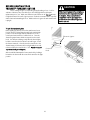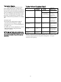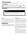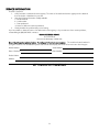
1
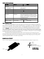
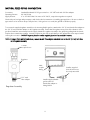
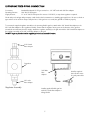
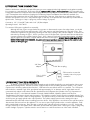
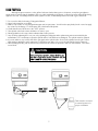
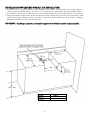
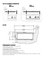
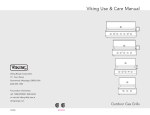
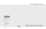
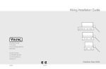
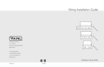
Viking Use/Installation Guide
Outdoor Built-In
TruSearTM Infrared Griller
Viking Range Corporation
111 Front Street
Greenwood, Mississippi 38930 USA
IMPORTANT:
PLEASE READ AND FOLLOW
DANGER
* Before beginning, please read these instructions
completely and carefully.
• Do not remove permanently affixed labels, warnings, or
plates from product. This may void the warranty
• Please observe all local and national codes and
ordinances.
• The installer should leave these instructions with the
consumer who should retain for local inspector’s use and
for future reference
If you smell gas:
1. Shut off gas to the appliance.
2. Extinguish any open flame.
3. Open lid.
4. If odor continues, keep away from the appliance
and immediately call your gas supplier or your
fire department.
WARNING
Installation must conform with local codes or in the
absence of codes, the National Fuel Gas Code, ANSI
Z223.1. In Canada: Installation must be in accordance
with the current CAN/CGA-B149.1, Natural Gas and
Propane Installation Code or CAN/CGA-B149.2, Propane
Storage and Handling Code and/or local codes.
1. Do not store or use gasoline or other
flammable vapors and liquids in the vicinity of
this or any other appliance.
2. Any LP cylinder not connected for use shall
not be stored in the vicinity of this or any
other appliance.
WARNING
GENERAL INFORMATION
WARNING: This outdoor gas side burner is not
intended to be installed in or on recreational vehicles
and/or boats.
• Keep area clear and free from combustible materials,
gasoline, and other flammable vapors.
• When the outdoor gas grill is not in use, the gas supply
must be turned off at the LP gas supply cylinder.
• The pressure regulator and hose assembly supplied with
the unit must be used. Replacement pressure
regulators and hose assemblies must be those specified
by the manufacturer.
• Finding a leak is not a “do-it-yourself” procedure.
Some leaks can only be found with the burner control in
the on position and this must be done by a qualified
technician.
• The LP supply cylinder to be used must be constructed
and marked in accordance with the specifications for LPgas cylinders of the U.S. Department of Transportation
(DOT) or the National Standard of Canada, CAN/CSAB339, Cylinders, Spheres, and Tubes for the
Transportation of Dangerous Goods.
• Gas Manifold Pressure Natural gas - 4.0” W.C.P.
LP/Propane - 10.0” W.C.P.
• If the following instructions are not followed exactly, a
fire causing death or serious injury may occur:
-Do not store a spare LP gas cylinder under or near
this appliance.
-Never fill the cylinder beyond 80 percent full.
2
If not installed, operated and maintained in
accordance with the manufacturer’s instructions,
this product could expose you to substances in
fuel or fuel combustion which can cause death
or serious illness and which are known to cause
cancer, birth defects or other reproductive harm.
For example, benzene is a chemical which is
part of the gas supplied to the cooking
product. It is consumed in the flame during
combustion. However, exposure to a small
amount of benzene is possible if a gas leak
occurs. Formaldehyde and soot are byproducts of incomplete combustion. Properly
adjusted burners with a bluish rather than
yellow flame minimize incomplete combustion.
SAFETY TIPS
•Keep outdoor cooking appliance area free from
combustible materials, gasoline and other
flammable vapors and liquids.
•Keep ventilation openings at the rear of the cart
and cylinder free and clear to allow proper air
flow. Do not obstruct the flow of combustion and
ventilation air.
•Spiders and insects can nest in the burners of the
grill and block the gas and air flow tothe burner
ports. This may cause a fire from behind the
manifold cover. Inspect and clean burners
periodically.
BASIC SPECIFICATIONS
Description
Overall Width
Overall Depth
To end of landing ledge
To end of knobs
Overall Height
Cutout Width
Cutout Depth
Cutout Height
Gas
Requirements
Infrared Burner
Rating
Approximate Shipping
Weight
VGIB242T
26 1/4” (66.7 cm)
VGIB151T
15-5/16” (38.9 cm)
31-9/16” (80.2 cm)
32-5/8” (82.9 cm)
10 1/2” (26.3 cm)
14” (35.6 cm)
Natural:
LP/Propane:
55 lbs. (24.8 kg)
24 3/4” (62.9 cm)
27-1/2” (69.9 cm)
10-1/4” (26.0 cm)
standard residential 1/2” (1.3 cm) ID gas service line.
equipped with high capacity hose/regulator assembly for
connection to standard 5gal, 20 lb. LP/Propane gas cylinder
with Type 1, QCC-1 connection or standard residential 1/2”
(1.3 cm) ID gas service line.
21,500 BTU Nat./20,000 BTU LP
(6.3 kW Nat./5.9 kW LP)
160 lbs. (72.0 kg)
GAS CONNECTION
Verify the type of gas supply to be used, either natural or LP, and make sure the marking on the rating plate
agrees with that of the supply. Never connect an unregulated gas line to the appliance. An installer supplied gas shutoff valve must be installed in an easily accessible location. All installer supplied parts must conform to local codes, or
in the absence of local codes, with the National electrical Code, ANSI/NFPA 70 and the National Fuel Code, ANSI
Z223.1. In Canada: Installation must be in accordance with the current CAN/CGA-B149.1, Natural Gas Installation
Code or CAN/CGA-B149.2, Propane Installation Code and/or local codes. All pipe sealants must be an approved type
and resistant to the actions of LP gas. Never use pipe sealant on flare fittings. All gas connections should be made by
a competent technician and in accordance with local codes and or ordinances. In the absence of codes, the installation
must comply with the National Fuel Gas Code ANSI Z223.1.
The gas burner and its individual shut-off valve must be disconnected from the gas supply piping system
during any pressure testing of that system at test pressures in excess of 1/2 PSIG (3.5 kPa). The unit must be isolated
from the gas supply piping system by closing its individual manual shut-off valve during any pressure testing of that
system at test pressures equal to or less than 1/2 psi (3.5 kPa).
BURNER ADJUSTMENT
There is no burner adjustment for the infrared burner. Once heated, the flames should glow a bright red color.
1/4”
(.64 cm)
FLAME HEIGHT
TruSear BURNER
Orifice
3
NATURAL FIXED PIPING CONNECTION
Connection:
Operating Pressure:
Supply Pressure:
Standard Residential 1/2” ID gas service line - 1/2” NPT male with 1/2” flare adapter.
4.0” W.C.P. Nat.
6” to 14” W.C.P. Nat. If in excess of 14” W.C.P., a step-down regulator is required.
Check with your local gas utility company or with local codes for instructions on installing gas supply lines. Be sure to check on
type and size of run and how deep to bury the lines. If the gas line is too small, the grill will not function properly.
To connect the supplied regulator assembly to the incoming flexible gas line, attach with a 1/2” (1.3 cm) female flare adapter to
the 1/2” (1.3 cm) male flare adapter on the regulator assembly. Ensure that the regulator arrow points in the direction of the
gas flow towards the unit and away from the supply. Attach the regulator assembly to the grill unit by pulling back the female
coupler sleeve towards the regulator. Insert the coupler into the male coupler fitting on the grill until the sleeve snaps forward
securing the connection. DO NOT forget to place the installer supplied gas valve in an accessible location.
NOTE: If using a Viking GSH12 flexible hose, remove the 3/8” flare adapter and attach hose to the 1/2” (1.3 cm) male flare
on the regulator assembly.
Female
coupler sleeve
Regulator
Male
coupler
fitting
1/2” male
flare adapter
Regulator Assembly
Installer supplied
shut-off valve must
be easily accessible
Installer supplied flexible
gas line with 1/2”
female flare adapter or
Viking GHS12
4
LP/PROPANE FIXED PIPING CONNECTION
Connection:
Operating Pressure:
Supply Pressure:
Standard Residential 1/2” ID gas service line - 1/2” NPT male with 3/8” flare adapter.
10.0” W.C.P. LP/Propane
11” to 14” W.C.P. LP/Propane If in excess of 14” W.C.P., a step-down regulator is required.
Check with your local gas utility company or with local codes for instructions on installing gas supply lines. Be sure to check on
type and size of run and how deep to bury the lines. If the gas line is too small, the grill will not function properly.
To connect the supplied regulator assembly to the incoming flexible gas line, attach with a 3/8” female flare adapter to the
3/8” male flare adapter to the regulator assembly. Ensure that the regulator arrow points in the direction of the gas flow
towards the unit and away from the supply. Attach the regulator assembly to the grill unit with the 3/8” female flare adapter on
the regulator assembly to the 3/8” male flare adapter on the grill.
DO NOT forget to place the installer supplied gas valve in an accessible location.
3/8” female
flare adapter
Regulator
3/8” Male
flare
adapter
3/8” male
flare adapter
Regulator Assembly
Installer supplied flexible gas line
with 3/8” female flare adapter or
Viking GHS12
5
Installer supplied
shut-off valve must
be easily accessible
LP/PROPANE TANK CONNECTION
Outdoor side burners orificed for use with LP/Propane gas come equipped with a high capacity hose/regulator assembly
for connection to a standard 20 lb. LP/Propane cylinder equipped with a Type 1, QCC-1 connector. Hose assembly must
comply with Elastomeric Composite Hose and Couplings for Conducting Propane and Natural Gas, CAN/CGA-8.1 standard
or the Theromplastic Hose and Hose Couplings for Conducting Propane and Natural Gas CAN1-8.3 standard (See
LP/Propane tank requirements below). Each tank is supplied with a dust cap. Place dust cap on cylinder valve outlet
whenever the cylinder is not in use. Only install the type of dust cap on the cylinder valve outlet that is provided with the
cylinder valve. Other types of caps or plugs may result in leakage of propane.
Connection: 1/2” (1.3 cm) NPT male with a 3/8” (.95) flare adapter
Operating Pressure: 10.0” W.C.P.
To connect to LP/Propane regulator/hose assembly:
Although the flow of gas is stopped when the connector is disconnected as part of its safety feature, you should
always turn the LP/Propane tank main valve “OFF” after each use and during transport of the tank or unit. First
connect the regulator to the grill unit by screwing the 3/8” flare coupling to the 3/8” flare adapter. Connect to the
tank valve by screwing the Type 1, QCC-1 connector to the LP/Propane tank. Open the tank valve and check the
connection between the regulator and the Type 1, QCC-1 fitting for leaks with a soapy water solution. If bubbles
appear, tighten the connection. Repeat until all leaks have been stopped. ALWAYS CHECK FOR LEAKS AFTER
EVERY LP/PROPANE TANK CHANGE. Any joint sealant used must be an approved type and be resistive to the
actions of LP/Propane gas
3/8” flare
adapter
3/8” flare coupling
Type 1, QCC-1
connector
*Tank must be mounted in
vertical position for proper
ventilation
LP/PROPANE TANK REQUIREMENTS
A dented or rusty LP/Propane tank may be hazardous and should be checked by your tank supplier. Never use a
cylinder with a damaged valve. All tanks should be equipped with an OPD (overfilling protection device). This is a DOT
requirement for all tanks purchased after October 1, 1998 and will ensure that the tank is not overfilled. The LP/Propane
tank should be a standard 5-gal, 20 lb. gas cylinder tank approximately 12” in diameter and 18” high which must be
constructed and marked in accordance with the Specifications for LP/Propane Gas Cylinders of the U.S. Department of
Transportation (D.O.T.) or the National Standard of Canada, CAN/CSA-B339, Cylinders, Spheres and Tubes for
Transportation of Dangerous Goods; and Commission. The cylinder connection device must be compatible with the Type
1, QCC-1 connector on the outdoor cooking appliance. The cylinder must be provided with a shut-off valve terminating in
an LP/Propane gas supply cylinder valve outlet specified. The cylinder supply system must be arranged for vapor
withdrawal and provided with a listed overfilling prevention device. If the appliance is stored indoors the cylinder must be
disconnected and removed from the appliance. Do not store a spare LP-gas cylinder under or near this appliance. Each
tank is supplied with a dust cap. Place dust cap on cylinder valve outlet whenever the cylinder is not in use. Only install
the type of dust cap on the cylinder valve outlet that is provided with the cylinder valve. Other types of caps or plugs may
result in leakage of propane. Cylinders must be stored outdoors in a well-vented area out of the reach of children.
6
LEAK TESTING
Although all gas connections on the grill are leak tested at the factory prior to shipment, a complete gas tightness
check must be performed at the installation due to possible mishandling in shipment or excessive pressure unknowingly being
applied to the unit. Periodically check the whole system for leaks, or immediately check if the smell of gas is detected.
1. Do not smoke while leak testing. Extinguish all flames.
2. Never leak test with an open flame.
3. Make a soap solution of one part liquid detergent and one part water. You will need a spray bottle, brush or towel to apply
the solution to the fittings. For LP/Propane units, check with a full cylinder.
4. Check that all control knobs are in the “OFF” position.
5. Turn cylinder valve knob counter clockwise one turn to open.
6. Blowing bubbles in the soap solution indicates that a leak is present.
7. Stop a leak by tightening the loose joint or by replacing the faulty part with a replacement part recommended by the
manufacturer. Do not attempt to repair the cylinder valve if it should become damaged. The cylinder must be replaced.
8. If you are unable to stop a leak, shut off the gas supply at the cylinder valve. Remove the cylinder from the grill. Call an
authorized gas appliance service technician or LP/Propane gas dealer. Do not use the grill until the leak is corrected.
9. After checking for leaks, push in and turn any control knob to release the pressure in the hose and manifold. Turn off the
control knob.
CAUTION
Before placing into operation, always check for gas
leaks with a soapy water solution. DO NOT USE AN
OPEN FLAME TO CHECK FOR LEAKS!
LEAK TEST
POINTS
*Tank must be mounted
in vertical position for
proper ventilation
7
INSTALLATION PROCEDURES FOR BUILT-IN INSTALLATION
1. A minimum of 6” (15.2 cm) from the sides must be maintained from the side of the burner above the cooking surface to
adjacent vertical combustible surfaces. The unit is not to be located under overhead unprotected combustible surfaces.
2. It is desirable to allow at least 6” side clearance to non-combustible surfaces above the cooking surface for counter space.
3. When determining a suitable location for the unit, take into account concerns such as exposure to wind, proximity to traffic
paths and keeping gas supply lines as short as possible. Locate only in a well-ventilated area. Never locate in a building,
garage, breezeway, shed or other such enclosed areas.
IMPORTANT: Gas fittings, regulator, and installer supplied shut-off valve must be easily accessible.
A
MODEL
VGIB151T
VGIB242T
DIM A.
14” (35.6 cm)
24 3/4” (62.9 cm)
8
BUILT-IN CLEARANCE DIMENSIONS
15” W.
FRONT VIEW
24” W.
FRONT VIEW
Min. 6”
Min. 6”
(15.2 cm)
to combustible
surfaces
(15.2 cm)
to combustible
surfaces
15 5/16”
(38.9 cm)
26 1/4””
(66.7 cm)
SIDE VIEW
11 3/8”
(28.9 cm)
PERFORMANCE CHECKLIST
A qualified installer should carry out the following checks:
• All internal packaging removed.
• Specified clearances maintained to combustible materials.
• Pressure regulator connected and set.
• Manual shut-off valve installed and accessible.
• Check air shutter adjustment - sharp blue flame, no yellow tipping.
• Check for gas leaks (odors) at all gas connections.
• Each burner lights satisfactory, individually or with adjacent burners lit.
Any adjustments necessary that are the result of the installer not following instructions will be responsibility of the installer,
dealer or the end user of the product.
9
BEFORE LIGHTING YOUR
TRUSEARTM INFRARED GRILLER
CAUTION
Prior to turning the gas on, inspect the gas supply tubing or hose. Look for
evidence of abrasion, cuts, wear and tear, or other damage which could require
replacement prior to use. Make sure all burner control knobs are off. Do not attempt
to light the burner if the smell of gas is present. Check the connection with a soap and
water solution after attaching the hose. Make sure there is gas in the tank and the tank
is upright.
To light TruSear infrared griller:
Before lighting the burner, remove the stainless steel cover.
Push in, turn the TruSear infrared control knob until the High
position on the knob aligns with the indicator line on the
control panel and continue to hold the knob in. Press the
electronic ignition button which corresponds to the control
knob. You will hear a clicking sound. After the burner lights,
hold the control knob in for about 5 seconds longer or until
the burner remains lit. Once lit, turn the control knob to the
desired setting. If the burner does not light within 4 seconds,
release and turn the control knob to “off”. Wait 5 minutes for
any accumulated gas to dissipate.
Wait at least 5 minutes before relighting a
hot burner to allow any accumulated gas
to dissipate. Keep a spray bottle of
soapy water near the gas supply valve
and check the connections for gas leaks
before each use.
Electronic Ignitor
Control
Knob
After several failed attempts the burner can be lit by holding a
lit match to the burner with the control knob turned to the light
position.
10
TruSear Infrared Grilling tips
Infrared grilling produces intense heat
which quickly sears the meat. Searing locks in
flavor and juices while allowing the outer surface to
absorb smoke and food aroma that is produced as
grease and drippings are vaporized by the burner.
The result is a crisp, flavorful outside with a tender,
juicy inside. As a general rule, foods will cook in
about 1/2 the time they would take on an ordinary
grill.
•Preheat the grill.
•Ensure that meat is fully thawed and that all
excess fat is trimmed away prior to grilling.
•Leave the burner set on “HI” when placing food
on the grill to sear.
•For thicker cuts of meats, adjust burner to a lower
setting and continue cooking until desired
doneness is reached.
NOTE: When the TruSear infrared griller is not in
use, it must be covered with the provided stainless
steel cover for protection from outside elements
such as rain.
TruSear Infrared Cooking Chart*
FOOD
WEIGHT OR
THICKNESS
Chicken Breast, Bnls
CONTROL
SETTING
SUGGESTED
COOKING TIME
HI
2 - 3 mins each
side.
Cook 8 - 10 mins.
total. Turn
occasionally to
prevent burning
outside.
Reduce to medium
setting halfway
between Hi and LO
Hamburger
1/2 - 3/4” thick
HI
2 mins each side to
sear. Cook 6 - 8
mins. total. Turn
occasionally to
prevent burning.
Steaks, Ribeye
1 1/2 ” thick
HI
3 mins each side for
Rare.
4 mins each side for
medium.
Steaks, Filet
1” thick
HI
3 mins each side for
rare to med. rare
3 1/2 mins each side
for medium
Pork Chops
3/4” thick
HI
4 mins each side
*NOTE: These times are recommendations only. Variations in cuts
of meats and personal taste may alter cooking times. Use your
discretion when grilling.
11
CLEANING AND MAINTENANCE
Any piece of equipment works better and lasts longer when maintained properly and kept clean. Grilling equipment is no
exception. Your TruSearTM Infrared Burner must be kept clean and maintained properly.
TruSear Infrared Grill Burner
When finished cooking, turn the control knob to the “HI” setting and allow the burner to burn for Five
Minutes. This helps to eliminate any drippings or debris that would otherwise remain on the burner, degrading the
performance and reducing burner life. After the five minute burn-off time, turn the grill OFF and allow to cool
completely before attempting to clean or move. Wipe excess grease and food from grill surfaces.
NOTE: When the TruSear infrared griller is not use, it must be covered with the provided stainless steel cover for protection from
outside elements such as rain.
CAUTION
•Do not use a metal knife or any other metal tool to scrape stainless steel parts.
•Do not permit citrus or tomato juice to remain on stainless steel surfaces, as citric acid will
permanently discolor stainless steel. Wipe up any spills immediately.
•Do not use abrasive cleaners, steel wool pads, or abrasive cloths on stainless steel, painted parts or
brass parts.
•Do not use brass cleaners on the brass option parts. They are coated with an epoxy coating.
Drip Tray
The drip tray pans should be removed and cleaned
after each use. Allow the drippings in the the drip tray
pans to cool completely before removing. To remove the
drip tray pans, simply remove the pans from the tray. Place
the trays in hot, soapy water to clean. Wipe up any debris
that may have collected in the drip tray with a hot, soapy
towel. Dry and replace drip tray pans before next use.
REPLACEMENT PARTS
Only authorized replacement parts may be used in performing
service on the side burners. Do not repair or replace any part of
the outdoor grill unless specifically recommended in the manual.
All other servicing should be referred to a qualified technician.
Stainless Steel* Parts
Some stainless steel parts may have a plastic
protective wrap which must be peeled off. Do not expose
protective plastic film on the stainless steel to heat or direct
sunlight. It could melt onto the stainless steel parts and
become difficult to remove. The interior should be washed
thoroughly with hot, soapy water to remove film residues and
any dust or debris before being used, then rinsed and wiped
dry. Solutions stronger than soap and water are rarely
needed.
All stainless steel body parts should be wiped with
hot, soapy water and with a liquid cleaner designed for this
material. If buildup occurs, do not use steel wool, abrasive
cloths, cleansers, or powders! If it is necessary to scrape
stainless steel to remove encrusted materials, soak with hot,
wet cloths to loosen the material, then use a wool or nylon
scraper. Do not use a metal knife, spatula, or any other
material tool to scrape stainless steel! Scratches are almost
impossible to remove.
*Under rare conditions, such as an extremely salty
environment, small amounts of rust may accumulate on
stainless steel parts. These small amounts of surface
rust can easily be removed by applying Soft Scrub®
Gel to a damp sponge and wiping with the stainless
steel grain. It is important to make sure you wipe with
the grain for the most efficient removal of surface rust.
12
SERVICE INFORMATION
If service is required:
1. Call your dealer or authorized service agency. The name of the authorized service agency can be obtained
from the dealer or distributor in your area.
2. Have the following information readily available:
a. Model number
b. Serial number
c. Date purchased
d. Name of dealer from whom purchased
3. Clearly describe the problem that you are having.
If you are unable to obtain the name of an authorized service agency, or if you continue to have service problems,
contact Viking at (888) 845-4641 or write to:
VIKING PREFERRED SERVICE
111 Front Street
Greenwood, Mississippi 38930 USA
Record the information indicated below. You will need it if service is ever required. The model and serial number for
your grill is located on an identification plate located under the drip tray in the rear left corner next to the inlet pipe.
Model Number
Serial Number
Date of Purchase
Date Installed
Dealer’s Name
Address
KEEP THIS MANUAL FOR FUTURE REFERENCE
13
PROFESSIONAL SERIES
OUTDOOR BUILT-IN TruSearTM INFRARED GRILLER WARRANTY
ONE YEAR FULL WARRANTY
Built-in outdoor TruSear Infrared Grillers and all of their component parts, except as detailed below*, are warranted to be free from defective materials or
workmanship in normal household use for a period of twelve (12) months from the date of original retail purchase. Viking Range Corporation, warrantor,
agrees to repair or replace, at its option, any part which fails or is found to be defective during the warranty period.
*Painted, porcelain, and decorative items are warranted to be free from defective materials or workmanship for a period of ninety (90) days from the date
of original retail purchase. ANY DEFECTS MUST BE REPORTED TO THE SELLING DEALER WITHIN NINETY (90) DAYS FROM DATE OF ORIGINAL
RETAIL PURCHASE.
Viking Range Corporation uses the most up-to-date processes and best materials available to produce all color finishes. However, slight color variation
may be noticed because of the inherent differences in painted parts and porcelain parts as well as differences in kitchen lighting, product locations, and
other factors.
FIVE YEAR LIMITED WARRANTY
Any TruSear infrared burner which fails due to defective materials or workmanship in normal household use during the second through fifth year from the
date of original retail purchase will be repaired or replaced, free of charge for the part itself, with the owner paying all other costs, including labor.
LIFETIME LIMITED WARRANTY
Any stainless steel part (see 90-day porcelain provision above*), which rusts through due to defective materials or workmanship in normal household use
during the second through the useful lifetime of the unit from the date of original retail purchase will be repaired or replaced, free of charge for the part
itself, with the owner paying all other costs, including labor.
NINETY (90) DAY RESIDENTIAL PLUS WARRANTY This warranty applies to applications where use of the product extends beyond normal
residential use. Examples are, but not limited to, bed and breakfasts, fire stations, private clubs, churches, etc. This warranty excludes all
commercial locations such as restaurants, food service locations and institutional food service locations.
This warranty extends to the original purchaser of the product warranted hereunder and to each transferee owner of the product during the term of the
warranty.
This warranty shall apply to products purchased and located in the United States and Canada. Products must be purchased in the country where service
is requested. Warranty labor shall be performed by an authorized Viking Range Corporation service agency or representative. Warranty shall not apply to
damage resulting from abuse, accident, natural disaster, loss of electrical power to the product for any reason, alteration, improper installation, improper
operation, or repair or service of the product by anyone other than an authorized Viking Range Corporation service agency or representative. This
warranty does not apply to commercial usage. Warrantor is not responsible for consequential or incidental damage whether arising out of breach of
warranty, breach of contract, or otherwise. Some jurisdictions do not allow the exclusion or limitation of incidental or consequential damages, so the
above limitation or exclusion may not apply to you.
Owner shall be responsible for proper installation, providing normal care and maintenance, providing proof of purchase upon request, and making the
appliance reasonably accessible for service. If the product or one of its component parts contains a defect or malfunction during the warranty period,
after a reasonable number of attempts by the warrantor to remedy the defects or malfunctions, the owner is entitled to either a refund or replacement of
the product or its component part or parts. Warrantor’s liability on any claim of any kind, with respect to the goods or services covered hereunder, shall in
no case exceed the price of the goods or service or part thereof which gives rise to the claim.
WARRANTY SERVICE: Under the terms of this warranty, service must be performed by a factory authorized Viking Range Corporation service agent or
representative. Service will be provided during normal business hours, and labor performed at overtime or premium rates shall not be covered by this
warranty. To obtain warranty service, contact the dealer from whom the product was purchased, an authorized Viking Range Corporation service agent, or
Viking Range Corporation. Provide model and serial number and date of original purchase. For the name of your nearest authorized Viking Range
Corporation service agency, call the dealer from whom the product was purchased or Viking Range Corporation. IMPORTANT: Retain proof of original
purchase to establish warranty period.
The return of the Owner Registration Card is not a condition of warranty coverage. You should, however, return the Owner Registration Card so that
Viking Range Corporation can contact you should any question of safety arise which could affect you.
Any implied warranties of merchantability and fitness applicable to the above described TruSear infrared burner and stainless steel parts are limited in
duration to the period of coverage of the applicable express written limited warranties set forth above. Some jurisdictions do not allow limitations on how
long an implied warranty lasts, so the above limitation may not apply to you. This warranty gives you specific legal rights, and you may also have other
rights which may vary from jurisdiction to jurisdiction.
Specifications subject to change without notice
14
15
VIKING RANGE CORPORATION
111 Front Street
Greenwood, Mississippi 38930 USA
(662) 455-1200
For more product information,
call 1-888-VIKING1 (845-4641)
or visit the Viking Web site at
vikingrange.com
F20330D
(PS0606VR)