1
OWNER'S MANUAL
VESTAX CORPORATION
VESTAX EUROPE
CONGRATULATIONS !
Thank you for purchasing the Vestax CDX-16 CD Mixing Console. We
suggest that you read through this owner's manual thoroughly so that you
may enjoy the full use of this product safely and in the knowledge of all its
special features and suitable applications.
C A U T I O N
IMPORTANT SAFEGUARDS
F E AT U R E S
BEFORE USE
F U N C T I O N
CD SECTION
MIXER SECTION
F R O N T PA N E L
R E A R PA N E L
CONNECTION EXAMPLE
GETTING THE MOST OUT OF THE CDX-16
SPECIFICATIONS
2
4
5
6
6
7
11
11
12
12
13
14
CAUTION
RISK OF ELECTRIC SHOCK DO NOT OPEN
CAUTl0N:TO REDUCE THE RlSK OF ELECTRlC SHOCK
DO NOT REMOVE COVER(OR BACK)
NO USER-SERVICEABLE PARTS INSIDE
REFER SERVlCING T0 QUALIFIED SERVlCE PERSONNEL
The lightning flash with arrowhead symbol,within an equilateral triangle,is intended to
alert the user to the presence of uninsulated“dangerous voltage”within the product's
enclosure that may be of sufficient magnitude to consitute a risk of electric shock to persons.
The exclamation point within an equilateral triangle is intended to alert the user to the presence
of important operating and maintenance(servicing)instructions in the literature accompanying
the appliance.
T0 REDUCE THE RISK 0F FIRE 0R ELECTRlC SHOCK,DO NOT
EXPOSE THIS APPLIANCE T0 RAIN 0R M0ISTURE.
C A U T I O N : TO
PREVENT ELECTRIC SHOCK,MATCH BLADE OF PLUG TO
WIDE SLOT,FULLY INSERT
ATTENTION:P0UR
EVITER LES CH0CS ELECTRIQUES,INTRODUIRE LA
LAME LA PLUS LARGE DE LA FICHE DANS LA BORNE
CORRESP0NDANTE DE LA PRISE ET P0USSER JUSQU’AU
F0ND
2
NOTE
This equipment has been tested and found to comply with the limits for a Class B
digital device, pursuant to Part 15 of the FCC Rules. These limits are designed to
provide reasonable protection against harmful interference in a residential
installation. This equipment generates, uses and can radiate radio frequeney energy
and, If not installed and used in accordance with the lnstructions, may cause harmful
interference to radio communications. However, there is no guarantee that
interference will not occur in a particular installation. If this equipment dose cause
harmful interference to radio or television reception, which can be determined by
turning the equipment off and on, the user is encouraged to try to correct the
interference by one or more of the following measures.
●Reorient
or relocate the recelving antenna.
the separation between the equipment and receiver.
●Connect the equipment into an outlet on a circuit different from that to which the
receiver is connected.
●Consult the dealer or an experiencced radio/TV technician for help.
●Increase
NOTE
Changes or modifications may cause this unit to fail to comply wiht Part 15 of the
FCC Rules and may void the user's authority to operate the equipment.
This Class B digital apparatus meets all requirements of the Canadian Interference-Causing Equipment
Regulations.
Cet appareil numérique de la Classe B respecte toutesles exigences du Réglement sur le matérier brouilleur du
Canada.
HOW TO CONNECT A PLUG
IMPORTANT
The wires in the mains lead are coloured in
accordance with the following code:
BLUE-"NEUTRAL"("N")
BROWN-"LIVE"(L")
1.The BLUE wire must be connected to the terminal
which is marked with the letter "N" or coloured
BLACK.
2.The BROWN wire must be connected to the
terminal which is marked with the letter "L" or
coloured RED.
3.Do not connect either wires to the earth terminal in
the plug which is marked by the letter "E" or by the
safely earth symbol ↓or coloured green or greenand-yellow.
This apparatus is fitted with an approved moulded 13
Amp plug.To change a fuse in this type of plug
proceed as follows:
1.Remove fuse cover and fuse.
2.Fix new fuse which should be a BS1362 5A.
A.S.T.A. or BSI approved type.
3.Refit the fuse cover.
If the fitted plug is not suitable for your socket
outlets, It should be cut off and an appropriate plug
fitted in its place. It the mains plug conlains a fuse.
this should have a value of 5A. If a plug without a
fuse is used, the fuse at the distribution board
should not be greater than 5A.
NOTE
Betore replacing the plug cover, make cenain that the
cord grip is clamped over the sheath of the lead-not
simply over the two wires.
The severed plug must be destroyed to
avoid a possible shock hazard it be
inserted into a 13A socket elsewhere.
CLASS 1 LASEN PNOOCUT
LUOKAN 1 LASENLAITE KLASS 1
LASENAPPANAT
3
IMPORTANT SAFEGUARDS
READ BEFORE OPERATING EQUIPMENT
This product was designed and manufactured to meet strict quality and
safety standards. There are, however, some installation and operation
p r e c a ut ion s wh i ch yo u sh o u l d b e p a r t i c u l a r l y a w a r e o f .
1. Read instructions-All the safety and operating 10. Power sources-This product should be operated only
instructions should be read before the appliance is
from the type of power source indicated on the
operated.
marking label. If you are not sure of the type of
power supply to your home, consult your appliance
2. Retain instructions-The safety and operating
dealer or local power company.
instructions should be retained for future reference.
3. Heed Warnings-All warnings on the appliance and 11. Grounding or Polarization-This product is equipped
with a polarized alternating-current line plug (a plug
in the operating instructions should be adhered to.
having one blade wider than the other). This piug
4. Follow Instructions-All operating and use
will fit into the power outlet only one way. This is
instructions should be followed.
safety feature. If you are unable to insert the plug
5. Cleaning-Unplug this product from the wall outlet
fully into the outlet, try reversing the plug. If this
before cleaning. Do not use liquid cleaners or
should still fail to fit, contact your electrician to
aerosol cleaners. Use a damp cloth for cleaning.
replace your obsolete outlet. Do not defeat the safety
purpose of the polarized plug.
6. Attachments-Do not use attachments not
recommended by the product manufacturer as they 12. Power-Cord Protection-Power supply cords should
may cause hazards.
be routed so that they are not likely to be walked on
or pinched by intems placed upon or against them,
7. Water and Moisture-Do not use this product near
paying particular attention to cords at plugs,
water-for example, near a dath tub, wash bowl,
convenience receptacles, and the point where they
kitchen sink, or laundry tub, in a wet basement, or
exit from the appliance.
near a swimming pool, and the like.
8. Accessories-Do not place this product on an 13. Protective Attachment Plug-The appliance is
equipped with an attachment plug having overload
unstable cart, stand, tripod, or table. The product
protection. This is a safety feature. See Instruction
may fall, causing serious injury to a child or adult,
Manual for replacement or resetting of protective
and serious damage to the appliance. Use only with
device. If replacement of the plug is required, be
a cart,. stand, tripod, bracket, or table recommended
sure the service technician has used a replacement
by the manufacturer, or sold with product. Any
plug specified by the manufacturer that has the same
mounting of the appliance should follow the
overload protection as the original plug.
manufacturer's instructions, and sholud use a
mounting accessory recommended by the 14. Lightning-For added protection for this product
manufacturer.
during lightning storm, or when it is left unattended
and unused for long periods of time, unplug it from
9. Ventilation-Slots and openings in the cabinet are
the wall outlet. This will prevent damage to the
provided for ventilation and to ensure reliable
product due to lightning and power-line surges.
operation of the product and to protect it from
overheating, and these openings must not be blocked 15. Overloading-Do not overload wall outlets and
or covered. The openings should never be blocked by
extension cords as this can result in a risk of fire or
placting the product on a bed, sofa, rug, or other
electric shock.
similar surface. This product should never be placed 16. Object and Liquid Entry-Never push objects of any
near or over a radiator or heat register. This product
kind into this product through openings as they may
should not be placed in a built-in installation such as
touch dangerous voltage points or short-out parts
a bookcase or rack unless proper ventilation is
that could result in a fire or electric shock. Never
provided or the manufacturer's instructions have been
spill liquid of any kind on the product.
adhered to.
4
17. Servicing-Do not attempt to service product 19. Replacement Parts-When replacement parts are
required, be sure the service technician has used
yourself as opening or removing covers may expose
replacement parts specified by the manufacturer or have
you to dangerrous voltage or other hazards. Refer
the same characterristics as the original parts.
all servicing to qualified sersonnel.
Unauthorized substitutions may result in fire, electric
18. Damage Requiring Service-Unplug this product
shock or other hazards.
from the wall outlet and refer servicing to qualified
20. Safety Check-Upon completion of any service or
repairs to product, ask the service technician to
perfrom sefety checks to determine that the product is
in proper operating condition.
service personnel under the following conditions:
a. When the power-supply cord or plug is damage.
b. If liquid has been spilled or objects have fallen
into the product.
21. Carts and Stands-The appliance should be used only
c. If the product has been exposed to rain or water.
with a cart stand that is recommended by
d. If the product dose not operate normally by
manufacturer.
following the operating instructions. Adjust only
those controls that are coverd by the operating 22. An appliance and cart combination should be moved
instructions as an improper adjustment of other,
with care. Quick stops, excessive force, and uneven
controls may result in damage and will often
surfaces may cause the appliance and cart
require extensive work by a qualified technician
combination to overturn.
to restore the product to its normal operation.
e. If the product has been dropped or cabinet has
been damaged.
f. When the product exhibits a distinct change in
perfromance-this indicates need for service.
FEATURES
● Dual Top loading CD player. For quick loading of
CDs top loading systems offer unparalleled ease.
Further, the opaque plastic cover allows you to
visualize the current playing status of the unit unlike
front-loading players.
● Auto Smoothing. Between each track on any CD is
usually a few seconds of no signal. The CDX-16
incorporates technology that eliminates this
“blankness”with the result being a smooth blend
from the previous track to the current track playing.
● Inbuilt mixer. The CDX-16's inbuilt mixer allows
you to mix CD, phono, and line sources without the
connection of an external mixing console. To choose
the input source or CD which will be mixed, simply
switch to the desired input using the input assign
switch.
● Anti Skip & Anti Jump. The buffer memory on the
CDX-16 is sufficient to eliminate any skipping from
vibrations or pressure. The suspension system also
prevents low frequency sounds from causing similar
skips or jumps whilst the CD is playing.
● Cue Point. This function allows you to set a cue
point on a given CD and to access this point quickly
and easily.
● Pitch Control. The playing pitch of either CD can be
adjusted with the use of the pitch control fader or the
pitch may be bent with the pitch bend joystick. The
pitch range can be set to two levels, +/-8 or +/-16.
Pitch range is most useful when attempting to best
match the playing pitch of one track with another for
smooth beat mixing.
● Standby Mode. If the CD is left unattended or on
pause mode for an extended period (approximately
10 minutes) the unit will go into sleep/auto standby
mode. This feature has been included to promote the
life of each mechanism as constant playing will wear
down the quality of the laser and reduce the amount
of enjoyment that you may have with the CDX-16.
● Joystick. The two (2) joysticks on the CDX-16
allow users to quick scan the CD, search easily for a
known track and to pitch bend the track playing.
Pitch bend allows you to adjust to pitch momentarily
in order to fine tune your mix.
5
BEFORE USE
Using CDs.
A conventional CD consists of two (2) sides. Typically one side bears a label stating the name of the CD and artist
whilst the front side, rainbow like in its color, contains the information that makes this technology work. There are
approximately six (6) million data items stored on any one given CD front surface. Please make sure to load the
CD into the playing mechanism correctly, so that the front side (rainbow) is unable to be seen once the lid is
closed.
Unlike conventional analog turntables, CD technology uses a fine laser beam instead of a stylus to read the
contents of the disc. As a result of there being little physical contact, a CD will take infinitely longer to degrade.
Repeated use of a CD, even playing over the same track again and again will likely have very little effect on the
audible quality of the discs data.
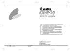
However, the front surface of a CD is brittle and may be scratched or damaged if you are careless in its handling.
Thus, please take care to load you CDs correctly and ensure that you store them in a safe place. Furthermore,
avoid leaving CDs in direct sunlight or in close proximity to a heating device or hot object, in the rain or in water,
or on surfaces that have excessive moisture or surface dirt/grime. Also take care when cleaning any CD by using a
recommended or special purpose cleaning cloth, cleaning spray or product and always wipe in the direction
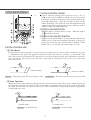
illustrated below.
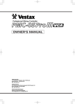
●Wipe from the inside out.
●Do not wipe in a circular fashion.
●Never use record cleaner designed for conventional analog disks, this will degrade the CD disc surface.
■Always store disc properly in the case.
Warning
・Please do not inhibit access to this unit's main switch by operating it in a confined area.
・Do not expose to water, moist environments or operate this device in an area likely to be effected by liquid
spillage or dripping.
FUNCTIONS
■TOP
6
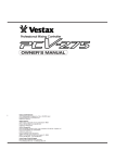
CD SECTION
①PITCH CONTROL FADER
Used to adjust the playing pitch (speed) by up to +/- 8%, +/16%. As this fader is 100mm in length you are able to make
both major and subtle adjustments in the playing pitch of any
given CD sound source. Typically, this fader is used to make
subtle adjustments that allow for beat matching/mixing that
results in you ultimately being able to move from one track to
another without an audible difference.
②PITCH LOCK INDICATOR
When the light is on Pitch Lock is active. When the light is
off Pitch Lock is inactive.
③PITCH LOCK ON/OFF SWITCH
When selected, and the light is on, the pitch of the CD playing
will be set to a pitch neutral position regardless of the pre-set
pitch level or how the pitch control fader is adjusted. When
Pitch Lock is set to off, the pitch control fader is active.
④STICK CONTROLLER
[1] Pitch Bend
By pressing the stick towards the rear panel (up) of the console you are able to make a momentary negative
(-) adjustment in the pitch. The opposite movement (down) will result in a positive (+) adjustment in the
pitch. The joystick will automatically spring back to a neutral position and any pitch adjustments will hence
stop. You can use this feature to give the track a little push or a little pull or you can use it to create some
interesting effects.
(→FRONT PANEL)
(→FRONT PANEL)
stick up → The pitch (speed) decreases by up to -20%
stick down → The pitch (speed) increases by up to +20%
[2] Scan Function
Whilst the CD is in play mode pressing the joystick to the left will scan the CD in reverse whilst pressing the
joystick to the right will scan forward. This speed setting is dependent on the angle of the joystick. The flatter
the angle the faster the scan speed and vice versa. The scan function is easily used to find an approximate
starting point on a track
↓
(FRONT SIDE)
↓
(FRONT SIDE)
stick left → Scans backward.
stick right → Scans forward.
7
[3] Search Function
Whilst pause is activated, the joystick when moved from left to right will do so in 1-75 frame units for the
purpose of aiding track or point search. This is especially useful when recalling an exact start point far from
the start or end point or a particular track.
stick left → Scans backward.
■
stick right → Scans forward.
The information (data) on a CD is written at approximately 75 frames per second.
⑤PREVIOUS BUTTON
Used for skipping backwards to the starting point of the current track (when pressed once). If pressed twice, the
return point is the starting point of the previous track. The number of times this button is pressed (after the first
time) corresponds to the number of tracks back the starting point returns to.
⑥NEXT BUTTON
Used for skipping forward to the starting point of the next track. The number of times pressed determines the
number of tracks skipped ahead.
⑦PLAY/PAUSE BUTTON
Press this button to play a given track on the CD or to pause at any point on any track. Whilst in pause mode,
the CD will continue to spin but the point at which you pressed pause will be the starting point for when you
choose to push play.
⑧PLAY/PAUSE INDICATOR
This light indicates whether or not the unit is in play or in pause mode. When the light is on, the CD is in play
mode. If the indicator light is flashing then the CD is in pause mode.
⑨CUE BUTTON
The last pause point is always memorized and can be cued up by pressing the cue button. This function is
useful for instant cueing as the same position (pause point) can be recalled and played back with one easy
action.
A Cue Point will be lost when,
■ The unit is turned off.
■ The CD is played or the pause point is shifted. The new cue point will always be the point at which pause
was last set.
■ The stop button is pressed.
■ The applicable CD is ejected.
(A) Using the Cue function.
To set a cue point is simple and easy. Once you have found the section or point, which you want to cue
press the pause button. To check if your cue point is OK, hold down the cue button and the track will play
past this point. Release the cue button and the initial point from which you just played will be recalled.
When it comes time to play from the cue point first press the cue button to make sure that the point is
recalled and set and then press the play/pause button. Please note that unless you press pause again, the cue
point will remain at the first point set.
8
⑩CUE INDICATOR
When the cue point is set the LED will be on.
⑪SINGLE / CONTINUE BUTTON
This button is used to switch between single play, single repeat and all repeat modes.
When the unit is first switched on this mode will be set to OFF, meaning that at the end of the CD's final track
the CD will stop. Press the single/continue button once and the AUTO CUE SINGLE mode will be selected. Set
to this mode the current track will be repeated until it is stopped. Press the single/continue button twice (once
more) and the CONTINUE mode will be selected. In this mode the entire CD will be repeated upon the
conclusion of the final track until it is stopped.
REPEAT OFF
AUTO CUE SINGLE
CONTINUE
⑫DISPLAY / STOP BUTTON
When pressed the time indicated on the display will change to display;
■ Single remain (time remaining until conclusion of the current track).
■ Single elapse (time elapsed on the current track).
■ Total remain (time remaining until the conclusion of the final track of the CD).
***If the Display / Stop button is held for more than three (3) seconds the player will go into sleep mode. This
is especially useful in preventing the premature degradation of the units laser. The unit will automatically go
into sleep mode after approximately 10 minutes of inactive use.
Single remain
Single elapse
Total remain
⑬PITCH RANGE ASSIGN SWITCH
This switch changes the pitch range from +/- 8% to +/- 16%.
⑭PITCH RANGE INDICATOR
Indicates the current pitch range selection.
⑮OPEN BUTTON
Used to open the unit for easy access to the CD. As an inbuilt safety mechanism for top loading drives, a CD
can not be ejected until the mechanism has been stopped.
9
⑯DISPLAY
[1] Indication of motion status
Display
Status
Open
The top loading CD tray is open.
Read
No Disc
The CD mechanism is reading the TOC data from the CD.
The CD tray is closed and there is no disc or the disc has a
reading error.
Sleep
The CD mechanism/motor has been stopped.
[2] DISPLAY
aPLAY
cCONTINUE
bPAUSE
eTIME BAR
dAUTO CUE SINGLE
fPITCH DISPLAY
CONTINUE
AUTO CUE SINGLE
REMAIN
gTRACK No. hMINUTES iSECONDS jFRAMES
kREMAIN
(a) PLAY
The CD is in play mode.
(b) PAUSE
The CD is in pause mode.
(c) CONTINUE
The entire CD will be repeated upon the conclusion of the
final track.
(d) AUTO CUE SINGLE
The current track will be repeated.
(e) TIME BAR
This bar indicates the time remaining or elapsed (depending
on the display mode setting).
(f) PITCH DISPLAY
Displays the current pitch setting.
(g) TRACK No.
Current track number playing or on pause.
(h) MINUTES
Shows minute(s) respective to the display mode setting.
(i) SECONDS
Shows second(s) respective to the display mode setting.
(j) FRAMES
Shows the frame(s) respective to the display mode setting.
(k) REMAIN
Displays the current setting for the Display/Stop button.
10
MIXER SECTION
⑰ INPUT SELECT SWITCH
Used to select the input source (Phono, Line, CD) sent to the
designated PGM (A,B).
⑱ MONITOR SELECT SWITCH
Used to select the signal for monitoring (headphone). Selection is
made irrespective of the position of the crossfader and can be set to
either PGM A, B or to Mix. The selected PGM monitor signal can
be heard through the left (side) headphone whilst the main output
signal is heard in the right headphone. When set to MIX the master
signal can be monitored through both headphones in stereo.
⑲ INPUT LEVEL METER
This LED indicates the current level of each input signal for both
PGM A and PGM B.
⑳ PGM EQ VOLUME
Used to adjust the EQ, Hi (high) Lo (low) frequencies for each
PGM.
21 PGM VOLUME LEVEL
⃝
Used to control and adjust the input level of each PGM.
22 CROSS FADER
⃝
With the cross fader to the left, the output signal is PGM A.
Therefore, when the cross fader is to the right the output signal is
PGM B. As the cross fader is moved from one side to the other
there is a blend of the respective signals. This is such that when the
fader is in the neutral (center) position both signals can be heard.
The cross fader on the CDX-16 is user replaceable. When the cross
fader is worn out the fader may be easily removed and subsequently
replaced with the optional replacement fader CF-R3 Likewise,
preventative maintenance & cleaning of the fader may be
accomplished through such easy removal.
■
To replace the crossfader please follow the below instructions carefully.
( i ) Carefully remove the four (4) screws that fix the crossfader to the faceplate.
(ii) Gently remove the crossfader, making sure to disconnect all cables carefully.
(iii) Replace the crossfader unit, making sure to carefully connect all cables to their proper points.
(iv) Affix the crossfader unit to the faceplate with the previously removed four (4) screws.
FRONT PANEL
23 MIC INPUT JACK
⃝
25 HEADPHONE JACK
⃝
Input jack for MIC.
24 MIC VOLUME LEVEL
⃝
Input jack for MIC.
26 MONITOR VOLUME LEVEL
⃝
Used to control and adjust the level of the MIC input.
Used to control and adjust the volume level of the
monitor (headphones).
11
REAR PANEL
POWER
27 GROUND (GND) TERMINAL
⃝
30 MIX OUTPUT JACK
⃝
Connection of this terminal to the grounding out lead
of a turntable will reduce unnecessary hum and noise.
Used for the connection to a power amplifier.
31 CD OUTPUT JACK
⃝
28 PHONO INPUT JACK
⃝
Used to connect a turntable (MM moving magnet
type) to the CDX-16 unit. The signal from the
turntable is sent to the PGM channels when the phono
input is selected.
Each connection allows the output signal of each CD
player to be sent to an external unit. None of the
mixer features will affect the output signal when this
connection is used.
32 AC POWER CORD
⃝
29 LINE INPUT JACK
⃝
33
CD, MD, DAT, TAPE or other like playing ⃝POWER ON/OFF SWITCH
Please check that the volume level of a connected
equipment (-10dB - 0dB play levels) may be
power amplifier is at its minimum position prior to
connected through the line jacks. The respective
turning the CDX-16 unit either on or off.
signal is then sent through to either PGM when the
line input is selected.
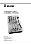
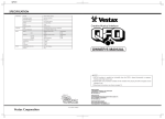
CONNECTION EXAMPLE
MIXER
[ex : VESTAX PMC-37PRO]
PROFESSIONAL MIXING CONTROLLER
INPUT SELECTOR
INPUT 1
MIC
PHONO 1
MAIN MIC
INPUT 2
LINE 1
PHONO 2
INPUT 3
LINE 2
PGM 1
MIN
MAX
BAL
LEVEL
LINE 4
PGM 3
+8
+5
+3
2
3
4
+1
3
4
GAIN
→ AMP
INPUT 4
PHONO 4
INPUT
ASSIGN
1
2
3
GAIN
MAX
LINE 3
INPUT
ASSIGN
1
2
MIN
PHONO 3
PGM 2
INPUT
ASSIGN
1
SUB MIC
BAL
4
GAIN
BAL
+0
-1
EQ
-3
HI
-5
MIN
MAX
MIN
MAX
L
ISOLATOR
LOW
MIN
MIN
R
MAX
L
ISOLATOR
ON
R
MIN
MAX
L
-7
R
-10
ISOLATOR
ON
ON
OFF
OFF
MAX
-15
OFF
CUE
OFF
MIC SEND
SPEAKER
SPEAKER
POWER AMP
[ex : VESTAX DA-X1000]
LOW
MID
LOW
HI
MID
SEND
-OOdB
LINE 1
FILTER
DJ/PHONO
PHONO
LINE 2
CD(R/RW)
LINE 3
LINE 4
MD
LINE 5
TAPE
LINE 6
LINE 7
GAIN
GAIN
LOW
MID LOW
MID
FILTER
MIN
MAX
FILTER
AUX 2
AUX 1
HI
MIN
AUX 1
MAX
FILTER
EQ
MIN
AUX 1
R
MAX
OFF
ON
CUE
B
MASTER
MIN
MAX
SUB MASTER LEVEL
OFF
POST
C.F. ASSIGN
A
AUX 2
PRE
OFF
POST
CUE
B
C.F. ASSIGN
A
OFF
ON
CUE
MIN
B
MASTER
OFF
MAX
ON
MAX
C.F. MODE
ON
0
AUX 2
PRE
POST
MAX
C.F. ASSIGN
MIN
MID HI
SWEEP
DRY
MASTER LEVEL
5 BAND MASTER EQ
LINE 8
+12dB
GAIN
SWEEP
DRY
L
MAX
OFF
GAIN
MASTER
-OOdB
FILTER
SWEEP
DRY
MAX
AUX 2
MIN
RCV
MASTER
MIC/AUX
R
POWER
BAL
FILTER
MIN
MIN
PRE
MIC
L
HI
RCV
SEND
A
GAIN
MID
+6dB
AUX 2
AUX 1
FRONT PANEL
POWER
LOW
HI
+6dB
AUX 1
PGM 1
PGM 2
PGM 3
LEVEL
LEVEL
LEVEL
MONITOR
MONITOR
SELECT
CUE
MASTER
MAIN VOLUME
OFF
-12dB
L
AUX 1 AUX 2
R
SPLIT
STEREO
BALANCE
MIN
MAX
SIGNAL/PEAK
LEVEL
MIN
MAX
SIGNAL/PEAK
LEVEL
MIN
MAX
SIGNAL/PEAK
LEVEL
MIN
MAX
SIGNAL/PEAK
LEVEL
MIN
MAX
MONITOR LEVEL
SIGNAL/PEAK
LEVEL
MIN
MAX
PHONES
MIC
MIC/AUX IN
CROSS FADER
LINE 1
MONITOR
REC OUT
MASTER
MIC/AUX
DJ/PHONO
PGM2
LINE IN
CD(R/RW)
CDR/RW 1
L
MD
TAPE
R
SELECT
MIN
MAX
LEVEL
PHONES
LINE IN
MIX OUT
CD/B OUT
A
B
PHONES
PGM1
LINE IN
CD/A OUT
POWER
GND
PHONO IN LINE IN
OUTPUT
GND
OUTPUT
TURN TABLE
〔ex:VESTAX PDX-2000〕
CD PLAYER
〔ex:VESTAX CDX-35〕
12
GETTING THE MOST OUT OF THE CDX-16
1.Switch your CDX-16 on, you'll find the on/off switch on the left side of the
rear panel.
2.Open the CD tray(s) and put in your CD. Make sure that the CD has been
placed flat and in the tray with the front side facing the mechanism (so that
you can see the label side through the tray's window. Close the tray
3.Press the PLAY button.
4.The CD will now be playing and you will be able to fully control the CDís
status through all the various controls. For example if you want to skip
ahead to track number 5 and to cue up to start at 01.30.00, use the NEXT
button to first get you to track number 5. Set the CD to PAUSE and then use
the joystick controller to search ahead to the 01.30.00 mark. Press the PLAY
button to start playing from that point. Alternatively, once you have gotten to
track number 5 simply use the joystick to scan through to approximately
01.25.00 and then release the joystick. If you press the PAUSE button at
precisely 01.30.00 you will have set yourself a CUE point that you can recall
at anytime, regardless of the tracks playing status. From this CUE point
simply press the PLAY button to continue.
5.Now that you have mastered the playing functions you may wish to turn your
attention to improving your DJ mixing skills. With both CD units active you
can easily mix between either CD 1 or CD 2. Depending on your monitoring
setting is what you will hear. Please play around with this feature until you
have confidently become accustomed to cuing you tracks up with another
playing. To mix between the CDs playing is simple with the crossfader. Of
course, with great input options you can also cue up an external source.
6.When you have finished your session be sure to turn your CDX-16 off in
order to prevent unnecessary degradation to your CD mechanisms. To do this
just hold down the STOP button for longer than three seconds. Please check
that you have stopped both CD1 and CD2 before turning your CDX-16 off at
the power switch.
13
S P E C I F I C AT I O N S
Total Power requirement
Weight
Dimensions (W×H×D)
CD SECTION
Quantization
Sampling Frequency
Digital Filter
Shock Proof Memory
Error Correcting System
Harmonic Distortion
Frequency response
Signal To Noise Ratio
Channel Separation
CD OUT
Mechanism Mount
MIXER SECTION
Frequency Response
Cross Talk
Signal To Noise Ratio
Headphone Level
115V/230V AC, 35W
6.8kg
441×321×126 (mm)
16bit liner
44.1kHz
8 times over sampling
16Mbit, 10sec
CIRC
Less than 0.03%
20Hz∼20kHz ±2dB
More than 85dB
More than 80dB
2Vrms
Magnetic chucking top mount
CD mechanism
20Hz∼20kHz ±2dB (MIX OUT)
60dB
75dB
1.4Vrms (32ohm Load)
14
Vestax Corporation
DEC.2002.CDX16E①