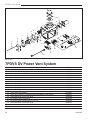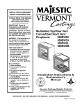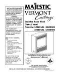
1
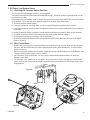
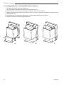
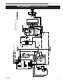
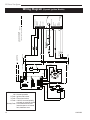
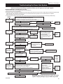
DV Power Vent System
Model 7PDVS
WARNING!
IF THE INFORMATION IN THIS MANUAL IS
NOT FOLLOWED EXACTLY, A FIRE OR
EXPLOSION MAY RESULT CAUSING
PROPERTY DAMAGE,PERSONAL INJURY
OR LOSS OF LIFE.
FOR YOUR SAFETY
WHAT TO DO IF YOU SMELL GAS:
• Do not try to light any appliance.
• Do not touch any electric switch; do not use
any phone in your building.
• Extinguish all flames.
• Immediately call your gas supplier from
•
your neighbours phone. Follow the gas
suppliers instructions.
If you cannot reach your gas supplier call
the fire department.
FOR YOUR SAFETY
DO NOT STORE OR USE GASOLINE OR
OTHER FLAMMABLE VAPOURS AND
LIQUIDS IN THE VICINITY OF THIS OR
ANY OTHER APPLIANCE.
Homeowner’s Installation and
Operating Manual
• Installation and service must be performed
by a qualified installer, service agency or
your gas supplier.
DE S I GN
CE
C E RT I F I E D
RTIFI E D
INSTALLER: Leave this manual with the appliance.
CONSUMER: Retain this manual for future reference.
10003262 8/06 Rev. 3
DV Power Vent System
Table of Contents
General Information .................................................................................................... 3
Power System Parts and Description ......................................................................... 4
Clearance to Combustibles ........................................................................................ 5
Restrictor Plate Orifice Size and Models Chart .......................................................... 6
Installing the DV Power Vent System ......................................................................... 7
Changing the Restrictor Orifice Plate ............................................................. 7
Install the Vent Pipes and the DV Power Vent System Box ........................... 8
Venting Up ...................................................................................................... 9
Venting Down ................................................................................................ 10
DV Power Vent System Setup .................................................................................. 11
Checking the Pressure Switch Position ........................................................ 11
Wire Connections ......................................................................................... 11
Adding Deflectors to Vent Termination .......................................................... 12
Wiring Diagram (Honeywell Ignition Module) ................................................ 13
Wiring Diagram (Synetek Igntion Module) .................................................... 14
Operation Instructions .............................................................................................. 15
Maintenance ............................................................................................................. 15
Changing the Restrictor Plate Orifice After System is Installed ................................ 16
Troubleshooting (Honeywell Electronic Ignitor) ........................................................ 18
Troubleshooting (Synetek Electronic Ignitor) ............................................................ 19
Replacement Parts ................................................................................................... 20
2
10003262
DV Power Vent System
General Information and Instructions for
the DV-Power Vent System Model 7PDVS
• This DV Power Vent System was designed to be
used only on units with electronic ignition (EN or EP).
• This DV Power Vent System was certified by CSA
to be used only with CFM Corporation Direct Vent
models, as listed in this manual.
• This DV Power Vent System can be used with any
CFM Corporation side wall vent termination kits,
vertical vent termination kits or snorkel kits (rear vent
termination not to be used).
• This DV Power Vent System must be installed by a
qualified professional according to these instructions.
• Plan the venting layout before starting the installation.
• Maximum TOTAL allowable system length is 40FT
of straight pipe, plus up to five 90 degree elbows.
Any combination of 45 and 90 degree elbows up to a
maximum of 450 degrees is allowed. It is NOT permissible to substitute elbows for length of horizontal
or vertical straight pipe.
• Can be vented down to a maximum of 12FT, measured from the center line of the highest section to the
centre line of the lowest section between the fireplace
and the DV Power Vent box.
• Minimum vent length of straight pipe between fireplace and the DV Power Vent box is:
10 feet for units with input up to 33,000BTU/h;
15 feet for units with inputs from 33,000BTU/h
to 40,000BTU/h.
• Maximum vent length of straight pipe between the
DV Power Vent System box and the vent termination
is 6 FT.
10003262
• Only vent components manufactured by CFM Corporation are approved for use with this DV Power Vent
System.
• All 4” and 7” venting connections (twist-lock or
crimped ends) to be sealed with high temperature
silicone.
• The 4” and 7” pipes connected to the inlet side of the
DV Power Vent System box to be fitted inside the 4”
pipe and the 7” collar.
• Leave a permanent access for inspection and service
of the DV Power Vent System box.
• Confined area definition: when the distance of the
four walls around the sides of the Power Vent Box to
the stand-offs is 3” or less in average.
• When the DV Power Vent box is installed in a confined area, the access door needs to have a minimum size of 12” X 12” and it must be ventilated with
a minimum of 10% open area. In a confined area
installation a minimum distance of 12” (1FT), needs
to be left between the Power Vent Box and the fifth
wall. (Refer to Figures on Page 5).
• When the DV Power Vent box is installed in an unconfined area, the access door doesn’t need to be
ventilated.
• The power vent motor shaft MUST ALWAYS BE oriented horizontally for proper operation.
• The pressure switch diaphragm MUST ALWAYS BE,
in a vertical position and the hose connection pointing down, NEVER up.
• Disconnect power supply when installing or servicing
the fireplace or the power vent system.
3
DV Power Vent System
DV Power Vent System Parts and Description:
1. DV POWER VENT box assembled with a 6FT power cord.
2. Two deflectors to be added to the side wall vent termination.
3. Assorted restrictor orifice plates to be used according to the instructions for specific models.
4. Installation and Operating Instruction Manual.
1
4
3
2
4
10003262
DV Power Vent System
Clearance to Combustible Materials and Access Door
•
The DV Power Vent System box needs a minimum 1” clearance all around the box.
The DV Power Vent System box already has a 1” stand-off on all sides.
•
Pipes from the fireplace to the DV Power Vent System box and from the box to the vent termination need:
• Clearance to combustible materials of 1” all around the pipe on vertical sections.
• Clearance to combustible materials of 1” on sides and bottom, and 2” on the top of horizontal sections.
12"
Min.
12"
Min.
Confined Area Access Door Suggestions
CFM501
Power vent
min. clearance
10/02
10003262
5
DV Power Vent System
Restrictor Orifice Sizes and Models
After you plan the venting lay-out and before the installation of the power vent box, check the following chart to make
sure the correct orifice is installed.
The power vent box is shipped with the 29/32” restrictor plate orifice in place, used for 36LDVT or 36LDVR models.
For all other models, replace the restrictor plate orifice with the correct size according to the following chart:
Models
6
Input (BTU/h)
Restrictor Orifice Size
33BDVT or 33BDVR
15,000
23/32”
36BDVT or 36BDVR
18,000
29/32”
DVR33
20,000
31/32”
39BDVT or 39BDVR
22,000
31/32”
43BDVT or 43BDVR
25,000
1”
DVRT36
25,000
1”
DV360
30,000
1¹⁄₃₂”
DVRT39
30,000
1¹⁄₃₂”
DVRT43
33,000
1¹⁄₁₆”
360DVS2 or 360DVS3 or 360DVSL or 360DVSR
38,000
1¹⁄₄”
DV580
38,000
1¹⁄₄”
33LDVR or 33LDVT
16,000
29/32”
36LDVR or 36LDVT
19,500
29/32”
39LDVR or 39LDVT (NG)
23,000
31/32”
39LDVR or 39LDVT (LP)
22,500
31/32”
43LDVR or 43LDVT (NG)
26,000
1”
43LDVR or 43LDVT (LP)
24,000
1”
33XDVR
21,500
31/32”
33XDV
21,500
31/32”
36XDV
27,500
1³⁄₈”
39XDV
31,000
1¹⁄₃₂”
10003262
DV Power Vent System
Installing the DV Power Vent System
1-Changing the Restrictor Orifice Plate:
Before installation of the power vent box (RECOMMENDED):
A. From the inlet side, remove the two 3/8” nuts holding the orifice plate.
B. Remove the orifice plate.
C. Install the correct restrictor orifice plate according to the chart above.
D. Place back the two nuts to hold the restrictor orifice plate and tighten.
Outlet
(To vent termination)
Inlet
(From fireplace)
10003262
7
DV Power Vent System
2-Install the Vent Pipes and the DV Power Vent System Box:
Install pipes and elbows according to the lay-out from
the unit to the Power Vent System Box and from it to
the vent termination. Follow the vent installation according to the fireplace manual recommendations.
Remember that the blower shaft MUST ALWAYS BE in
a horizontal plane and the pressure switch diaphragm
MUST ALWAYS BE in a vertical plane with the hose
connections pointing down.
Four different ways to install the Power Vent System Box.
Outlet
Inlet
Inlet
Outlet
Outlet
Outlet
Inlet
Inlet
8
10003262
DV Power Vent System
Venting Up:
L6
L7
L5
L4
A - Maximum 40FT of straight pipe.
B - Minimum 10FT of straight pipe for units up to 33,000BTU/h,
Minimum 15FT of straight pipe for units from 33,000BTU/h
to 40,000BTU/h.
L3
C - Maximum 6FT of straight pipe.
L2
L1
A = L1+L2+L3+L4+L5+L6+L7
B = L1+L2+L3+L4+L5
C = L6+L7
In the above example there are:
4 times 90 degrees elbows = 360 degrees
2 times 45 degrees elbows = 90 degrees
Total elbow degrees = 450 degrees
Installation is OK
10003262
9
DV Power Vent System
Venting Down:
A - Maximum 40FT of straight pipe.
B-Minimum 10FT of straight pipe for units up to 33,000BTU/h,
Minimum 15FT of straight pipe for units from 33,000BTU/h
to 40,000BTU/h.
C-Maximum 6FT of straight pipe.
L1
D-Maximum 12FT down.
A = L1+L 2+L3+L4+L5+L6
B = L1+L2+L3+L4
C = L 5+L6
D = L1+L 2
L5
L6
L2
L4
L3
In the above example there are:
4 times 90 degrees elbows = 360 degrees
2 times 45 degrees elbows = 90 degreees
Total elbow degrees = 450 degrees
Installation is OK
10
10003262
DV Power Vent System
3- DV Power Vent System Setup:
3.1 - Checking the Pressure Switch Position:
The pressure switch diaphragm must be in a vertical plane.
The pressure switch hose connections should NEVER point up. The BEST position is pointing down, but can
be pointed to the sides.
Depending on the final location of the DV Power Vent System box, the pressure switch hose connection needs
to be checked. If the hose connection position needs to be adjusted, follow these steps:
1. Check the pressure switch location;
2. If the hose connection is pointing down, you do not need to change the pressure switch position;
3. If the hose connection location needs to be adjusted, remove the two screws holding the pressure switch to
the bracket.
4. Rotate the pressure switch clockwise or counterclockwise (whichever is better to reach the new position);
5. Re-attach the pressure switch to the bracket with the same screws removed in Step 4.
6. Check all wire connections according to the wiring diagram.
7. Check hose connections between the pressure switch and the blower. Make sure the hose is not kinked.
(Refer to Figure A)
3.2 - Wire Connections:
• Remove one screw and one nut that are holding the circuit board cover in place. (Refer to Figure B) Bring
•
•
•
the cover, with the circuit board, the power cord and all the existing wires attached to it, to a rest position.
(Refer to Figure C)
Make all connections between the DV Power System box and the unit according to the wiring diagram. Use
18 gauge AWS wire with minimum 2/64” insulation.
For connections to the circuit board, use 3/16” Quick Connect female spade terminals, all others are
screwed connections.
The DV Power Vent System can be hard wired. To hard wire the DV Power Vent System, disconnect the
power cord from the circuit board and replace it with hard wiring according to the connections shown in the
wiring diagram.
Figure A
Nut
Screw
������
����
����
Figure C
Figure B
10003262
11
DV Power Vent System
3.3 - Adding Deflectors to the Side Wall Vent Termination:
1. Open the plastic bag and check all components.
(One Top Deflector, one Bottom Deflector, four self-tapping screws)
2. Install the bottom deflector using two screws provided with the kit. Refer to Figure A.
3. Open the top screen and install the top deflector. Refer to Figure B. Attach the top deflector using two screws
provided with the kit.
4. After installing the top and bottom deflectors the vent termination should look like Figure C.
5. Close the top screen to the same way it was before.
A
12
CFM514
CFM513
CFM512
B
C
10003262
DV Power Vent System
Wiring Diagram (Honeywell Ignition Module)
PILOT
12 3 4 5 6 8 9
Fireplace
120 VAC HOT
GREEN
TO WALL THERMOSTAT
OR ON/OFF SWITCH
Fireplace
1/4" QC TERMINAL
90fl FEMALE
24 VAC RET
BLACK
40VA TRANSFORMER
1/4" QC TERMINAL
90fl FEMALE
24 VAC HOT
120 VAC RTN
YELLOW
BLACK
GREEN
ORANGE
ORANGE
& INSTALLED WIRES
BLACK
BLACK
BLUE
NOVA SIT 822 VALVE
WHITE
BLACK
18 AWS SOLID, LOW VOLTAGE
MINIMUM INSULATION 2/64"
FIELD SUPPLIED
WIRE SPEC.:
RED
24V SENSE SPARK
24V
GND
GND
MV/VP PV
MV
Power Vent Kit
WHITE
Power Vent Kit
WHITE
BUSHING
BLACK
HOT
RTN
Hose
COM
NO NC
BLUE
YELLOW
13
10003262
HONEYWELL IGNITION MODULE
LO
HI
GREEN
DV Power Vent System
Wiring Diagram (Synetek Ignition Module)
120Vac Hot
Fan Rtn
120Vac Rtn
Key
Fan Hot
Flame Sense
Chasis / Burner Ground
LED
1/4” Male Tab
24Vac Hot (R)
Key
Thermostat (W)
Pilot Valve Hot
Main Valve Hot
Pilot / Main Valve Rtn.
J1
J2
Ignitor
Burner Ground
Pilot Valve
Main Valve
Power Vent Kit
Power Vent Kit
WHITE
BUSHING
WHITE
Fireplace
L1
120/220 Vac (Hot)
L2
120/220 Vac (Rtn)
Sensor
Fireplace
TO WALL THERMOSTAT
OR ON/OFF SWITCH
BLACK
HOT
RTN
Hose
COM
NO NC
BLUE
YELLOW
10003262
14
FIELD SUPPLIED & INSTALLED WIRES
WIRE SPEC.:
18 AWS SOLID, LOW VOLTAGE
MINIMUM INSULATION 2/64"
Normal operation
Ignition trial lockout
Flame loss lockout
120V AC reversed polarity
or board not sensing ground
Steady Flash Flame detected out of allowed sequence or internal
fault, hardware error
LED Codes
ON
2 Flash
3 Flash
5 Flash
Synetek
Ignition Module
CFM 10007939
GREEN
DV Power Vent System
Operation of the DV Power Vent System
Turn the switch ON/OFF or the wall thermostat, to the ON position.
Blower will start immediately and will purge the unit and the vent system for 45 seconds. At that point, the pilot will light
and the main burner(s) will follow.
When the switch ON/OFF or the wall thermostat, is turned to OFF, the main burner and the pilot will shut-down immediately and the blower will run for 45 seconds to clear the flue gases before turning OFF.
If the unit is ON but the flame is unstable (ON and OFF continuously), turn the switch to the OFF position and call a
serviceman to check the installation.
Maintenance
The DV Power Vent System box is a maintenance free system. The motor bearings are pre-lubricated for extended life
and no further lubrication is required.
It is recommended however to have the system checked once a year by a qualified professional.
10003262
15
DV Power Vent System
Changing the Orifice Plate After the DV Power Vent Box is Installed
If there is a need to change the restrictor plate orifice on the DV Power Vent System box, follow the steps below:
A. Turn the power OFF to fireplace and power vent.
B. Remove the blower’s cover (two parts):
•
•
•
•
•
•
Remove the hose attached to the blower casing.
Remove two screws. Refer to Figure A.
Remove two nuts from the right side cover.
Remove the right side cover by pulling it out. Refer to Figure B.
Remove two nuts from the left side cover.
Remove the left side cover by pulling it out. Refer to Figure C.
C. Remove the two nuts that hold the pressure switch bracket. Do not disconnect any wire or the hose. Just bring the
pressure switch still attached to the bracket to a rest position, to give you access to the screws that hold the blower
bracket. Refer to Figure D.
D. Disconnect the wires from the blower.
E. Remove the four screws that hold the blower bracket. Be careful not to drop the blower.
F. Slide down the blower to release it from the top extrusion and carefully bring the sub-assembly (blower with the bracket
and the gasket) to the outside of the box to replace the orifice; Be careful not to damage the gasket, otherwise you
will have to replace it. Refer to Figure E.
G. Remove the two 3/8” nuts holding the orifice plate. Refer to Figure F.
H. Get from the orifice plate kit the correct restrictor orifice size for the unit you are installing (check chart for restrictor
orifice size X unit model).
I. Install the correct orifice plate into the same location as the previous one.
J. Place back the two nuts.
K. Reinstall the blower. Make sure the exhaust of the blower is properly inserted into the opening.
L. Re-attach the blower bracket with the four screws removed in step “C”.
M. Connect the wires to the blower (see wiring diagram).
N. Re-attach the pressure switch to the original position and secure the two nuts removed in step “B”.
O. Re-install both covers to the blower:
•
•
•
•
Install the left side and secure it with the nuts.
Install the right side and secure it with the nuts.
Re-attach the two screws.
Re-attach the hose to the blower connection.
P. Check all wires according to the wiring diagram and the hose connections to make sure everything is properly
in place.
16
10003262
DV Power Vent System
Screws
Figure A
Figure D
Figure E
Figure B
Figure C
Figure F
10003262
17
DV Power Vent System
Troubleshooting the Power Vent System
SIT 822 Valve with Honeywell Electronic Ignitor and Synetek Power Vent Board
Service must be performed by a qualified installer, service agency or your gas supplier.
BEFORE COMMENCING TO TROUBLE SHOOT THE UNIT:
1. Check if there is power to the unit (fireplace) and to the power vent box.
2. Check if there is gas to the unit (fireplace).
3. The ignition control in the fireplace is equipped with a lockout device which will put the unit into a lockout condition after three attempts to ignite the pilot.
Follow the steps in the chart below to reset the control: Turn the On/Off switch to the off position, or turn the thermostat to the off position.
Wait 10 seconds and then turn to the “on” position.
4. If this is the first time that the unit has been fired, check the wiring of the unit against the wiring diagram before commencing troubleshooting.
START
Power vent motor
is working?
NO
ON/OFF switch or wall thermostat “ON”?
Is there 120V power to the fireplace and power vent?
Are all wiring connections tight? (Turn off Power before checking)
YES
YES
Is there 24V at the power vent circuit
board at the 24VAC Hot Terminal?
NO
Is there 24V from the transformer?
YES
Is there 120V Power to the motor?
YES
Replace
Blower
NO
Replace Power Vent Circuit Board
YES
Check Wiring
NO
Replace Transformer
Does the Pilot
Spark?
NO
Is there 24V power at terminal
six (24V) at the ignition board?
NO
YES
YES
Is the Pressure
Switch Closed?
NO
YES
Is the lead to the spark electrode
attached or arcing to ground?
Is the electrode cracked?
Replace Power
Vent Circuit Board
Is there a blockage in the vent?
Is there water/dirt in the hose from
NO
blower to the pressure switch?
Are hose connections loose?
Is the hose cracked?
Replace
Pressure
Switch
NO
Replace Ignition Module
Pilot Burner
Lights?
NO
Replace Ignition Module
NO
YES
NO
Is there 24V power at terminal
1 (MV) during spark cycle?
Is pilot gas line blocked?
Is pilot orifice blocked?
Are wires to valve loose
or corroded?
YES
NO
Are wires to valve
loose or corroded?
NO
Replace Gas Valve
Replace Ignition Module
Is there manifold pressure? YES
NO
NO
Replace Gas Valve
Check
position
of pilot.
Is orifice
blocked?
Replace Ignition Module
NO
Is the correct size of orifice restrictor installed in the power vent?
Does the pilot flame covers the flame rod?
Is the flame rod wire in good condition?
Is there continuity to ground from the pilot burner?
YES
Does pressure switch open during operation?
YES
NO
YES
Does 24V power get interupted at terminal six (24V) at the ignition module?
NO
Replace ignition module
18
NO
Is flame rod corroded?
Is pilot hood corroded?
Is flame rod insulator cracked?
Is wire to flame rod damaged?
Check Pilot for obstruction
Check Gas Pressure
Adjust Pilot Flame
YES
System Runs
Continuously
Until Switched
Off?
Does pilot flame cover
the flame rod?
NO
YES
Does Main
Burner Light?
YES
NO
YES
Does Spark
Stop When
Pilot Lights?
Is there 24V power at terminal
3 (PV) during spark cycle?
Is vent partially blocked?
Is there water/dirt in hose to
pressure switch?
Are hose connections loose?
Is the hose cracked?
NO
Replace
Pressure
Switch
Replace power vent circuit board
WARNING: Never jump the pressure switch out of this
system. Property damage, injury or death may result.
10003262
DV Power Vent System
Troubleshooting the Power Vent System
SIT 822 Valve with Synetek Electronic Ignitor and Synetek Power Vent Board
Service must be performed by a qualified installer, service agency or your gas supplier.
BEFORE COMMENCING TO TROUBLE SHOOT THE UNIT:
1. Check if there is power to the unit (fireplace) and to the power vent box.
2. Check if there is gas to the unit (fireplace).
3. The ignition control in the fireplace is equipped with a lockout device which will put the unit into a lockout condition after three attempts to ignite the pilot.
Follow the steps in the chart below to reset the control: Turn the On/Off switch to the off position, or turn the thermostat to the off position.
Wait 10 seconds and then turn to the “on” position.
4. If this is the first time that the unit has been fired, check the wiring of the unit against the wiring diagram before commencing troubleshooting.
START
Power vent motor NO
is working?
YES
ON/OFF switch or wall thermostat “ON”?
Is there 120V power to the fireplace and power vent?
Are all wiring connections tight? (Turn off Power before checking)
Is the LED light on the ignition control board giving an error code? (Refer to Page 14)
YES
YES
Is there 120V Power to the motor?
Is there 24V at the power vent circuit
board at the 24VAC Hot Terminal?
YES
Replace
Blower
NO
Replace Power Vent Circuit Board
NO
Check R & W from ignition control board are not crossed between power
vent circuit board and ignition control board. (R) 24V AC Hot must conReplace ignition control board
nect to 24V AC Hot at power vent circuit board. (W) Thermostat must
connect to ignition control Hot at power vent circuit board.
Does the Pilot
Spark?
NO
Is there 24V power at terminal
7 (24V) at the ignition board?
NO
YES
YES
Is the Pressure
Switch Closed?
NO
YES
Is the lead to the spark electrode
attached or arcing to ground?
Is the electrode cracked?
Replace Power
Vent Circuit Board
Is there a blockage in the vent?
Is there water/dirt in the hose from
blower to the pressure switch?
NO
Are hose connections loose?
Is the hose cracked?
Is the hose connected to the low
pressure side of the pressure
switch?
Replace
Pressure
Switch
NO
Replace Ignition Module
Pilot Burner
Lights?
NO
Replace Ignition Module
NO
YES
NO
Is there 24V power at terminal
2 main valve hot during spark
cycle?
NO
Is pilot gas line blocked?
Is pilot orifice blocked?
Are wires to valve loose
or corroded?
YES
NO
Are wires to valve
loose or corroded?
NO
Replace Gas Valve
Replace Ignition Module
Is there manifold pressure? YES
NO
Replace Gas Valve
Check
position
of pilot.
Is orifice
blocked?
Replace Ignition Module
NO
Is the correct size of orifice restrictor installed in the power vent?
Does the pilot flame covers the flame rod?
Is the flame rod wire in good condition?
Is there continuity to ground from the pilot burner?
YES
Does pressure switch open during operation?
YES
NO
YES
Does 24V power get interupted at terminal 7 (24V) at the ignition module?
NO
Replace ignition module
10003262
NO
Is flame rod corroded?
Is pilot hood corroded?
Is flame rod insulator cracked?
Is wire to flame rod damaged?
Check Pilot for obstruction
Check Gas Pressure
Adjust Pilot Flame
YES
System Runs
Continuously
Until Switched
Off?
Does pilot flame cover
the flame rod?
NO
YES
Does Main
Burner Light?
YES
NO
YES
Does Spark
Stop When
Pilot Lights?
Is there 24V power at terminal
3 (PV) during spark cycle?
Is vent partially blocked?
Is there water/dirt in hose to
pressure switch?
Are hose connections loose?
Is the hose cracked?
Is the hose connected to the
low pressure side of the pressure switch?
NO
Replace
Pressure
Switch
Replace power vent circuit board
WARNING: Never jump the pressure switch out of this
system. Property damage, injury or death may result.
19
DV Power Vent System
11
14
7
4
5
6
3
2
1
8
15
16
10
9
CFM Corporation reserves the right to make changes in design, materials, specifications, prices and discontinue colors and products at any time,
without notice.
7PDVS DV Power Vent System
Ref.
1.
2.
3.
4.
5.
6.
7.
8.
9.
10.
11.
12.
13.
14.
15.
16.
17.
18.
19.
20
Description
Hose High Temperature
Shield Heat Blower Right Assy
Shield Heat Blower Left Assy
Blower
Gasket Blower
Gasket Blower Plate
Pressure Switch
Circuit Board
Cover Circuit Board
Power Cord
Gasket Flue Pipe
Hose Clamp (Not Shown)
Wires (Circuit Board To Pressure Switch And Blower) (Not Shown)
Plate Restriction Orifice Size 29/32”
Kit Deflector Vent Termination
Kit Orifice Plates (Includes Items 17 To 25)
Plate Restriction Orifice Size 23/32”
Plate Restriction Orifice Size 25/32”
Plate Restriction Orifice Size 27/32”
7PDVS
10003405
10003673
10003672
10003214
10003066
10002280
10003213
10003230
10003610
10003095
10002237
10003267
10003317
10003260
10003315
10003258
10002274
10004194
10004195
10003262
DV Power Vent System
7PDVS DV Power Vent System
Ref.
20.
21.
22.
23.
24.
25.
Description
Plate Restriction Orifice Size 31/32”
Plate Restriction Orifice Size 1”
Plate Restriction Orifice Size 1¹⁄₃₂”
Plate Restriction Orifice Size 1¹⁄₁₆”
Plate Restriction Orifice Size 1¹⁄₄”
Plate Restriction Orifice Size 1³⁄₈”
10003262
(continued)
7PDVS
10003261
10003277
10003328
10003329
10003499
10009616
21
DV Power Vent System
22
10003262
DV Power Vent System
10003262
23
CFM Corporation
2695 Meadowvale Blvd. • Mississauga, Ontario, Canada L5N 8A3
800-668-5323 • www.cfmcorp.com