1
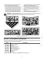
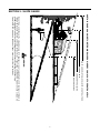
Operator’s Manual
Automatic Garden Tractor
IMPORTANT: READ SAFETY
RULES AND INSTRUCTIONS
CAREFULLY.
P. O. BOX 1386, KITCHENER, ONTARIO CANADA N2G 4J1
PRINTED IN UNITED-STATES
772C0748
(01/05)
TABLE OF CONTENTS
Content
Finding Your Model Number
Calling Customer Support
Important Safe Operation Practices
Safety Labels Found On Your Unit
Attachments and Accessories
Slope Gauge
Tractor Set-Up
Controls
Operation
Page
2
2
3
6
6
7
8
11
14
Content
Adjustments
Maintenance
Lubrication
Service
Off-Season Storage
Troubleshooting
Parts List/Pièces détachées
Warranty
Page
18
20
21
22
26
27
28
45
FINDING MODEL NUMBER
This Operator’s Manual is an important part of your new lawn tractor. It will help you assemble, prepare and
maintain the unit for best performance. Please read and understand what it says.
Before you start assembling your new equipment, please locate the model plate on the
equipment and copy the information from it in the space provided below. This information will be
necessary to use the manufacturer’s web site and/or help from the Customer Support Department
or an authorized service dealer.
•
You can locate the model number by looking beneath the seat. A sample model plate is explained below.
Model Number
Numéro de modèle
XXX-XXXXXX
Serial Number
Numéro de série
Copy the model number here:
XXXXXXXXXXX
TROYBILT - CANADA
KITCHENER, ON N2G 4J1
Copy the serial number here:
ENGINE INFORMATION
The engine manufacturer is responsible for all engine-related issues with regards to performance, power-rating,
specifications, warranty and service. Please refer to the engine manufacturer’s Owner’s/Operator’s Manual packed
separately with your unit for more information.
CALLING CUSTOMER SUPPORT
Please do NOT return the unit to the retailer from which it was purchased, without first contacting Customer Support.
If you have difficulty assembling this product or have any questions regarding the controls, operation
or maintenance of this unit, please call a Customer Support Representative 1-800-668-1238
Please have your unit’s model number and serial number ready when you call. See previous section
to locate this information. You will be asked to enter the serial number in order to process your call.
HOW TO OBTAIN SERVICE
Warranty service is available, WITH PROOF OF PURCHASE, through your local authorized service dealer. To
locate the dealer in your area;
Contact P.O. Box 1386, Kitchener, ON N2G 4J1, or call 1-800-668-1238 or log on to our Web site at
www.mtdcanada.com.
2
SECTION 1: IMPORTANT SAFE OPERATION PRACTICES
WARNING: This symbol points out important safety instructions which, if not followed, could endanger
the personal safety and/or property of yourself and others. Read and follow all instructions in this manual
before attempting to operate this machine. Failure to comply with these instructions may result in personal
injury. When you see this symbol—heed its warning.
DANGER: This machine was built to be operated according to the rules for safe operation in this manual. As with any type of power equipment, carelessness or error on the part of the operator can result in
serious injury. This machine is capable of amputating hands and feet and throwing objects. Failure to
observe the following safety instructions could result in serious injury or death.
GENERAL OPERATION
11. Do not put hands or feet near rotating parts or
under the cutting deck. Contact with the blade(s)
can amputate hands and feet.
12. A missing or damaged discharge cover can cause
blade contact or thrown object injuries.
13. Stop the blade(s) when crossing gravel drives,
walks, or roads and while not cutting grass.
14. Watch for traffic when operating near or crossing
roadways. This machine is not intended for use on
any public roadway.
15. Do not operate the machine while under the
influence of alcohol or drugs.
16. Mow only in daylight or good artificial light.
17. Never carry passengers.
18. Disengage blade(s) before shifting into reverse.
Back up slowly. Always look down and behind
before and while backing to avoid a back-over
accident.
19. Slow down before turning. Operate the machine
smoothly. Avoid erratic operation and excessive
speed.
20. Disengage blade(s), set parking brake, stop engine
and wait until the blade(s) come to a complete stop
before removing grass catcher, emptying grass,
unclogging chute, removing any grass or debris, or
making any adjustments.
21. Never leave a running machine unattended. Always
turn off blade(s), place transmission in neutral, set
parking brake, stop engine and remove key before
dismounting.
22. Use extra care when loading or unloading the
machine into a trailer or truck. This unit should not
be driven up or down ramp(s), because the unit
could tip over, causing serious personal injury. The
unit must be pushed manually on ramp(s) to load or
unload properly.
23. Muffler and engine become hot and can cause a
burn. Do not touch.
24. Check overhead clearances carefully before driving
under low hanging tree branches, wires, door
openings etc., where the operator may be struck or
pulled from the unit, which could result in serious
injury.
1. Read, understand, and follow all instructions on the
machine and in the manual(s) before attempting to
assemble and operate. Keep this manual in a safe
place for future and regular reference and for
ordering replacement parts.
2. Be familiar with all controls and their proper
operation. Know how to stop the machine and
disengage them quickly.
3. Never allow children under 14 years old to operate
this machine. Children 14 years old and over
should read and understand the operation
instructions and safety rules in this manual and
should be trained and supervised by a parent.
4. Never allow adults to operate this machine without
proper instruction.
5. To help avoid blade contact or a thrown object
injury, keep bystanders, helpers, children and pets
at least 75 feet from the machine while it is in
operation. Stop machine if anyone enters the area.
6. Thoroughly inspect the area where the equipment
is to be used. Remove all stones, sticks, wire,
bones, toys, and other foreign objects which could
be picked up and thrown by the blade(s). Thrown
objects can cause serious personal injury.
7. Plan your mowing pattern to avoid discharge of
material toward roads, sidewalks, bystanders and
the like. Also, avoid discharging material against a
wall or obstruction which may cause discharged
material to ricochet back toward the operator.
8. Always wear safety glasses or safety goggles
during operation and while performing an
adjustment or repair to protect your eyes. Thrown
objects which ricochet can cause serious injury to
the eyes.
9. Wear sturdy, rough-soled work shoes and closefitting slacks and shirts. Loose fitting clothes and
jewelry can be caught in movable parts. Never
operate this machine in bare feet or sandals.
10. Be aware of the mower and attachment discharge
direction and do not point it at anyone. Do not
operate the mower without the discharge cover or
entire grass catcher in its proper place.
3
6. Keep all movement on the slopes slow and gradual.
Do not make sudden changes in speed or direction.
Rapid engagement or braking could cause the front
of the machine to lift and rapidly flip over backwards
which could cause serious injury.
7. Avoid starting or stopping on a slope. If tires lose
traction, disengage the blade(s) and proceed
slowly straight down the slope.
25. Disengage all attachment clutches, depress the
brake pedal completely and shift into neutral before
attempting to start engine.
26. Your machine is designed to cut normal residential
grass of a height no more than 10”. Do not attempt
to mow through unusually tall, dry grass (e.g.,
pasture) or piles of dry leaves. Dry grass or leaves
may contact the engine exhaust and/or build up on
the mower deck presenting a potential fire hazard.
27. Use only accessories and attachments approved
for this machine by the machine manufacturer.
Read, understand and follow all instructions
provided with the approved accessory or
attachment.
28. Data indicates that operators, age 60 years and
above, are involved in a large percentage of riding
mower-related injuries. These operators should
evaluate their ability to operate the riding mower
safely enough to protect themselves and others
from serious injury.
29. If situations occur which are not covered in this
manual, use care and good judgment. Contact your
authorized dealer for assistance.
DO NOT:
1. Do not turn on slopes unless necessary; then, turn
slowly and gradually downhill, if possible.
2. Do not mow near drop-offs, ditches or
embankments. The mower could suddenly turn
over if a wheel is over the edge of a cliff, ditch, or if
an edge caves in.
3. Do not try to stabilize the machine by putting your
foot on the ground.
4. Do not use a grass catcher on steep slopes.
5. Do not mow on wet grass. Reduced traction could
cause sliding.
6. Do not shift to neutral and coast downhill. Overspeeding may cause the operator to lose control of
the machine resulting in serious injury or death.
7. Do not tow heavy pull behind attachments (e.g.
loaded dump cart, lawn roller, etc.) on slopes
greater than 5 degrees. When going down hill, the
extra weight tends to push the tractor and may
cause you to loose control. (e.g. tractor may speed
up, braking and steering ability are reduced,
attachment may jack-knife and cause tractor to
overturn).
SLOPE OPERATION
Slopes are a major factor related to loss of control and
tip-over accidents which can result in severe injury or
death. All slopes require extra caution. If you cannot
back up the slope or if you feel uneasy on it, do not mow
it.
For your safety, use the slope gauge included as part of
this manual to measure slopes before operating this
unit on a sloped or hilly area. If the slope is greater than
15 degrees as shown on the slope gauge, do not
operate this unit on that area or serious injury could
result.
CHILDREN
1. Tragic accidents can occur if the operator is not
alert to the presence of children. Children are often
attracted to the machine and the mowing activity.
They do not understand the dangers. Never
assume that children will remain where you last
saw them.
a. Keep children out of the mowing area and in
watchful care of a responsible adult other
than the operator.
b. Be alert and turn machine off if a child enters
the area.
c. Before and while backing, look behind and
down for small children.
d. Never carry children, even with the blade(s)
shut off. They may fall off and be seriously
injured or interfere with safe machine
operation.
e. Use extreme care when approaching blind
corners, doorways, shrubs, trees or other
objects that may block your vision of a child
who may run into the machine.
f. To avoid back-over accidents, always
disengage the cutting blade(s) before
DO:
1. Mow up and down slopes, not across. Exercise
extreme caution when changing direction on
slopes.
2. Watch for holes, ruts, bumps, rocks, or other
hidden objects. Uneven terrain could overturn the
machine. Tall grass can hide obstacles.
3. Use slow speed. Choose a low enough speed
setting so that you will not have to stop or shift while
on the slope. Tires may lose traction on slopes
even though the brakes are functioning properly.
Always keep machine in gear when going down
slopes to take advantage of engine braking action.
4. Follow the manufacturer’s recommendations for
wheel weights or counterweights to improve
stability.
5. Use extra care with grass catchers or other
attachments. These can change the stability of the
machine.
4
h. Never over fill fuel tank. Fill tank to no more
than ½ inch below bottom of filler neck to
allow space for fuel expansion.
i. Replace gasoline cap and tighten securely.
j. If gasoline is spilled, wipe it off the engine and
equipment. Move unit to another area. Wait 5
minutes before starting the engine.
k. To reduce fire hazards, keep machine free of
grass, leaves, or other debris build-up. Clean
up oil or fuel spillage and remove any fuel
soaked debris.
l. Never store the machine or fuel container
inside where there is an open flame, spark or
pilot light as on a water heater, space heater,
furnace, clothes dryer or other gas
appliances.
m. Allow a machine to cool at least 5 minutes
before storing.
shifting into reverse. The “Reverse
Caution Mode” should not be used when
children or others are around.
g. Keep children away from hot or running
engines. They can suffer burns from a hot
muffler.
h. Remove key when machine is unattended to
prevent unauthorized operation.
2. Never allow children under 14 years old to operate
the machine. Children 14 years old and over should
read and understand the operation instructions and
safety rules in this manual and should be trained
and supervised by a parent.
TOWING
1. Tow only with a machine that has a hitch designed
for towing. Do not attach towed equipment except at
the hitch point.
2. Follow the manufacturers recommendation for
weight limits for towed equipment and towing on
slopes.
3. Never allow children or others in or on towed
equipment.
4. On slopes, the weight of the towed equipment may
cause loss of traction and loss of control.
5. Travel slowly and allow extra distance to stop.
6. Do not shift to neutral and coast downhill.
GENERAL SERVICE:
1. Never run an engine indoors or in a poorly
ventilated area. Engine exhaust contains carbon
monoxide, an odorless, and deadly gas.
2. Before cleaning, repairing, or inspecting, make
certain the blade(s) and all moving parts have
stopped. Disconnect the spark plug wire and ground
against the engine to prevent unintended starting.
3. Periodically check to make sure the blades come to
complete stop within approximately (5) five seconds
after operating the blade disengagement control. If
the blades do not stop within the this time frame,
your unit should be serviced professionally by an
authorized dealer.
4. Check brake operation frequently as it is subjected
to wear during normal operation. Adjust and service
as required.
5. Check the blade(s) and engine mounting bolts at
frequent intervals for proper tightness. Also, visually
inspect blade(s) for damage (e.g., excessive wear,
bent, cracked).
Replace the blade(s) with the original equipment
manufacturer’s (O.E.M.) blade(s) only, listed in this
manual. “Use of parts which do not meet the original
equipment specifications may lead to improper
performance and compromise safety!”
6. Mower blades are sharp. Wrap the blade or wear
gloves, and use extra caution when servicing them.
7. Keep all nuts, bolts, and screws tight to be sure the
equipment is in safe working condition.
8. Never tamper with the safety interlock system or
other safety devices. Check their proper operation
regularly.
9. After striking a foreign object, stop the engine,
disconnect the spark plug wire(s) and ground
against the engine. Thoroughly inspect the machine
for any damage. Repair the damage before starting
and operating.
SERVICE
SAFE HANDLING OF GASOLINE:
1. To avoid personal injury or property damage
use extreme care in handling gasoline. Gasoline is
extremely flammable and the vapors are explosive.
Serious personal injury can occur when gasoline is
spilled on yourself or your clothes which can ignite.
Wash your skin and change clothes immediately.
a. Use only an approved gasoline container.
b. Never fill containers inside a vehicle or on a
truck or trailer bed with a plastic liner. Always
place containers on the ground away from
your vehicle before filling.
c. When practical, remove gas-powered
equipment from the truck or trailer and refuel
it on the ground. If this is not possible, then
refuel such equipment on a trailer with a
portable container, rather than from a
gasoline dispenser nozzle.
d. Keep the nozzle in contact with the rim of the
fuel tank or container opening at all times until
fueling is complete. Do not use a nozzle lockopen device.
e. Extinguish all cigarettes, cigars, pipes and
other sources of ignition.
f. Never fuel machine indoors.
g. Never remove gas cap or add fuel while the
engine is hot or running. Allow engine to cool
at least two minutes before refueling.
5
nal equipment specifications may lead to improper
performance and compromise safety!”
12. Do not change the engine governor settings or
over-speed the engine. The governor controls the
maximum safe operating speed of the engine.
13. Maintain or replace safety and instruction labels, as
necessary.
14. Observe proper disposal laws and regulations for
gas, oil, etc. to protect the environment.
10. Never attempt to make adjustments or repairs to
the machine while the engine is running.
11. Grass catcher components and the discharge
cover are subject to wear and damage which could
expose moving parts or allow objects to be thrown.
For safety protection, frequently check components
and replace immediately with original equipment
manufacturer’s (O.E.M.) parts only, listed in this
manual. “Use of parts which do not meet the origi-
WARNING: YOUR RESPONSIBILITY Restrict the use of this power machine to persons who read,
understand and follow the warnings and instructions in this manual and on the machine.
MAX 20%
S30544
S30011
Safety Labels found on your unit
SECTION 2: ATTACHMENTS & ACCESSORIES
The following attachments and accessories are compatible for your Garden Tractor. See the retailer from which you
purchased your tractor, an Authorized Service Dealer.
MODEL
OEM-190-604
OEM-190-607
OEM-190-603
OEM-190-608
OEM-190-842
OEM-190-822
OEM-190-823
OEM-190-824
OEM-190-825
OEM-190-841
490-900-0025
DESCRIPTION
Yard-Mate™ Storage Container/Toolbox (mounts on rear of tractor)
Deluxe Tractor Sunshade
Bumper Kit
Sleeve Hitch, Manual Lift
Triple Bagger Grass Collector
46-inch Front Dozer Blade
42-inch Two-stage Snow Thrower
Sleeve Hitch with Electric Lift
30-inch Hydraulic Tiller†
Mulch Kit
Deck Wash Kit
† 190-824 is required for use of this attachment. 190-608 cannot be used in its place.
6
SECTION 3: SLOPE GAUGE
D
R
EPR
E
S
ENT
ING
A
1
5
° SL
OPE
OR A FENCE POST
A CORNER OF A BUILDING
A POWER POLE
SIGHT AND HOLD THIS LEVEL WITH A VERTICAL TREE
USE THIS PAGE AS A GUIDE TO DETERMINE SLOPES WHERE YOU MAY NOT OPERATE SAFELY.
FOL
D ON
O
T
T
ED L
INE,
15°
WARNING
Do not mow on inclines with a slope in excess of 15 degrees (a rise of approximately 2-1/2 feet every 10 feet). A
riding mower could overturn and cause serious injury. If operating a walk-behind mower on such a slope, it is
extremely difficult to maintain your footing and you could slip, resulting in serious injury.
Operate RIDING mowers up and down slopes, never across the face of slopes.
7
SECTION 4: TRACTOR SET-UP
NOTE: Reference to RIGHT or LEFT side of the
tractor in this manual is observed from operator’s
position.
WARNING: Do NOT operate the tractor
without first attaching both the steering
wheel AND the seat. Doing so could result
in serious injury to the operator.
ATTACHING THE BATTERY CABLES
NOTE: There are two different styles of steering
NOTE: The battery cables may or may not be
wheel cap. See Figure 2. Styles vary by model.
attached on your unit. If the cables are not attached,
please follow the instructions below.
•
NOTE: The positive battery terminal is marked Pos.
•
(+). The negative battery terminal is marked Neg. (–).
•
•
•
•
The positive cable (heavy red wire) is secured to
the positive battery terminal (+) with a hex bolt and
hex nut at the factory. Make certain that the rubber
boot covers the terminal to help protect it from
corrosion.
Remove the hex bolt and wing nut from the
negative cable.
Remove the black plastic cover, if present, from the
negative battery terminal and attach the negative
cable (heavy black wire) to the negative battery
terminal (–) with the bolt and wing nut.
Make certain the battery retainer rod is in position
over the battery, securing it in place. See Figure 1.
Rubber
Boot
•
•
•
•
Steering
Wheel Cap
Hex Bolt
& Washer
Battery
Positive
Terminal
Steering
Shaft
Wing
Nut
Negative
Terminal
Using your hands, place the tractor’s front tires in
position for straight-ahead travel.
Remove the steering wheel cap from the center of
the steering wheel. Be careful not to lose the hex
screw and cupped washer found beneath it.
Place the steering wheel (in position for straightahead travel) directly onto the steering shaft found
in the center of the tractor’s dash.
Place the cupped washer (cupped side DOWN)
over the steering shaft.
Thread the hex screw into the steering shaft and
tighten securely.
Reinsert the steering wheel cap in the center of the
steering wheel. Refer to Figure 2.
Shoulder Bolt
Battery
Retainer Rod
Figure 2
Figure 1
ATTACHING THE SEAT
NOTE: If the battery is put into service after the date
NOTE: For shipping reasons, seats are either
fastened to the tractor seat’s pivot bracket with a plastic
tie, or mounted backward to the pivot bracket. In either
case, free the seat from its shipping position and
remove the two hex screws (or knobs, on models so
equipped) from the bottom of seat before proceeding
with applicable instructions below.
shown on top of battery, charge the battery as
instructed on page 23 of this manual prior to operating
the tractor.
ATTACHING THE STEERING WHEEL
In the event your tractor was crated with the steering
wheel and the seat removed for shipping reasons, use
the following instructions to properly assemble the
parts.
8
Quick Adjustment Seat
TIRE PRESSURE
NOTE: If your seat was shipped mounted backwards
on the seat pivot bracket, pull out the tab found on the
seat stop and hold it open while sliding the seat off the
seat pivot bracket. See Figure 3 .
WARNING: Maximum tire pressure under
any circumstances is 30 p.s.i. Equal tire
pressure should be maintained at all times.
The tires on your unit may be over-inflated for shipping
purposes. Reduce the tire pressure before operating
the tractor. Recommended operating tire pressure is
approximately 10 p.s.i for the rear tires & 14 p.s.i. for
the front tires. Check the sidewall of tire for maximum
p.s.i.
1. Line up the plastic seat spacers with the slots in
seat pivot bracket.
2. Slide seat in until front seat spacer engages the
seat stop.See Figure 3 .
WARNING: Before operating this machine,
make sure the seat is engaged in the seat
stop, stand behind the machine and pull back
on seat until fully engaged into stop.
ATTACHING THE CUTTING DECK 54”
DECK
WARNING: Before attaching the cutting
Quick Adjustment
deck, engage the parking brake, turn the
ignition key to the OFF position and remove
the key from the switch to avoid accidental
starting.
Seat Stop
•
Tab
Pivot Bracket
•
Figure 3
•
GAS AND OIL FILL-UP
•
The gasoline tank is located under the hood and has a
capacity of either two or three gallons. Do not overfill.
WARNING: Use extreme care when
Adjust the deck roller height so that the clevis pins
are inserted in the second hole (from the top) of
both the left-hand deck roller bracket and the righthand deck roller bracket. See Figure 4 or refer to
Deck Roller Height Adjustment .
Raise the deck lift arms up and out of the way by
placing the deck lift lever in the top notch on the
right fender.
Gently slide the cutting deck beneath the tractor
from the right side.
Move the cutting deck into position so that the
hooks found on the front end of the deck fit snugly
around the deck stabilizer rod as shown in Figure 4.
NOTE: The stabilizer rod may be secured to the
tractor frame with a plastic cable tie for shipping
reasons. If so, carefully cut the cable tie before
mounting the front of the cutting deck.
handling gasoline. Gasoline is extremely
flammable and the vapors are explosive.
Never fuel machine indoors or while the
engine is hot or running. Extinguish
cigarettes, cigars, pipes, and other sources of
ignition.
•
•
Service the engine with gasoline and oil as
instructed in the separate engine manual packed
with your tractor. Read instructions carefully.
IMPORTANT: Your tractor is shipped with oil;
however, you MUST check the oil level before
operating. Be careful not to overfill. Overfilling with oil
may cause the engine to smoke. This will result in poor
engine performance and could cause permanent
engine damage.
Lower the deck lift arms by placing the lift lever in
the bottom notch on the right fender.
Pull the deck support pin (on the left side of the
deck) outward and align it with the hole on the rear
of the left deck lift arm before releasing the pin to
lock it in place as shown in Figure 4. Repeat on the
right side.
INSTALLING THE PTO/DECK BELT
•
•
WARNING: The mowing deck is capable of
throwing objects. Failure to operate the riding
mower without the discharge cover in the
proper operating position could result in
serious personal injury and/or property
damage.
9
Make certain that the PTO/Deck belt is routed
around the spindle pulleys (found beneath the belt
guards) and both idler pulleys as illustrated in inset
in Figure 4 before proceeding.
Insert a 3/8” drive ratchet wrench (set to “loosen”)
into the hole on the idler bracket and pivot the
wrench handle clockwise. This will relieve the
tension on the deck idler.
IMPORTANT: Be certain that the FLAT side of the
IMPORTANT: After mounting the cutting deck, refer
PTO/Deck belt is the side coming in contact with the
deck idler pulleys.
to Leveling the Deck in the ADJUSTMENTS section of
this manual. Perform any adjustments, if necessary,
prior to operating the tractor.
•
With the tension relieved, carefully route the belt
around the electric PTO clutch as shown in Figure
4.
Idler Pulley
Deck Lift Assembly
Notches
Lift Cables
Deck Lift
Arms
Left-Hand
Idler Brkt.
3/8" Sq.
Hole
Belt Guard
Spring
Deck Idler Pulleys
Fender
Belt Guard
Lift Lever
PTO / Deck Belt
Deck Support Pins
Belt Guard
Deck Roller Bracket
Spindle Pulleys
Deck
Stabilizer
Bracket
Front of Tractor
Discharge Chute
Electric PTO Clutch
Deck Stabilizer Rod
NOTE: Many tractor components not shown for clarity.
Figure 4
10
SECTION 5: CONTROLS
F
A*
G
H
B
I
A* PTO lever
J
K
C
L
M
D
E
NOTE: Steering Wheel not shown for clarity.
A* PTO (Power Take-off) Lever (Models with manual PTO)
PTO (Power Take-off) Knob (Models with electric PTO)
B Choke Control
C Parking Brake Button
D Shift Lever
E Cup Holder
F Systems Indicator Monitor/Hour Meter
G
H
I
J
K
L
M
Throttle Control Lever
Ignition Switch
Brake Pedal
Drive Pedal
Cruise Control Button
Seat Adjustment Lever
Deck Lift Lever
NOTE: Any reference in this manual to the RIGHT or LEFT side of the tractor is observed from operator’s position.
* Tractors vary by model and are equipped with either a PTO lever or a PTO knob, NEVER both.
11
THROTTLE CONTROL LEVER
IGNITION SWITCH
The throttle control lever is located on the right side of
the tractor’s dash panel. This lever controls the speed
of the engine and, on some models, when pushed all
the way forward, the choke control also. When set in a
given position, the throttle will maintain a uniform
engine speed. See Figure 5.
Choke
Position
WARNING: Never leave a running machine
unattended. Always disengage PTO, move
shift lever into neutral position, set parking
brake, stop engine and remove key to prevent
unintended starting.
To start the engine, insert the key into the ignition
switch and turn clockwise to the START position.
Release the key into the NORMAL MOWING MODE
position once the engine has fired.
Fast
Position
To stop the engine, turn the ignition key
counterclockwise to the STOP position. See Figure 6.
Fast
Position
Normal
Driving
Mode
Stop
Position
Slow
Position
Slow
Position
Start
Position
Figure 5
IMPORTANT: When operating the tractor with the
cutting deck engaged, be certain that the throttle lever
is always in the FAST (rabbit) position.
CHOKE CONTROL
Figure 6
The choke control can be found
on the left side of the dash panel
and is activated by pulling the
knob outward. Activating the
choke control closes the choke
plate on the carburetor and aids
in starting the engine. Refer to
STARTING THE ENGINE in the
OPERATION section of this
manual for detailed starting
instructions.
IMPORTANT: Prior to operating the tractor, refer to both
Safety Interlock Switches, page 14 and Starting The Engine, page
15 of this manual for detailed instructions regarding the
Ignition Switch Module and operating the tractor in
REVERSE CAUTION MODE.
DRIVE PEDAL
The drive pedal is located
below the brake pedal on the
right front side of the tractor
along the running board.
Depress the drive pedal with
your right foot when the
tractor shift lever is in either
FORWARD or REVERSE to
cause the tractor to move.
Ground speed is also
controlled with the drive
pedal. The further down the pedal is depressed, the
faster the tractor will travel. The pedal will return to its
original position when it’s not depressed.
BRAKE PEDAL
The brake pedal is located on the
right front side of the tractor
above the drive pedal along the
running board. The brake pedal
can be used for sudden stops or
setting the parking brake.
NOTE: The brake pedal must
be fully depressed to activate the
safety interlock switch when
starting the tractor.
IMPORTANT: Always set the parking brake when
leaving the tractor unattended.
12
SYSTEMS INDICATOR MONITOR / HOUR
METER
ELECTRIC PTO (POWER
TAKE-OFF) KNOB
Your tractor is equipped with either an hour meter or an
ammeter as part of two available system indicator
monitors. Locate the monitor on the left side of your
dash panel and compare it to both shown in Figure 7.
To engage the power to the
cutting deck or other (separately
available) attachments on models
so equipped with an electric PTO,
pull outward on the PTO knob.
Push the PTO knob inward to
disengage the power to the cutting deck.
AMPS
Oil
NOTE: The PTO knob must be in the disengaged
Brake
Ammeter
Battery
(Blade Stop) position when starting the engine.
PTO
PTO (POWER TAKE-OFF) LEVER
Oil
+
Hour Meter
1/10
PTO
P
Brake
Brake —
Engage the parking brake.
On models equipped with a manual PTO, the PTO lever
is located on the left side of the dashboard next to the
steering wheel. Move the PTO lever forward to engage
the power to the cutting deck or other (separately
available) attachments; move the PTO lever rearward to
disengage the power.
PTO —
Move the PTO lever into the disengaged
(Blade Stop) position.
NOTE: The PTO lever must be in the disengaged
(Blade Stop) position when starting the engine.
Figure 7
If the Brake light or PTO light illuminates when
attempting to start the unit, proceed as follows:
It is normal for the Oil light and the Battery light to
illuminate while the engine is cranking, but if either
illuminates while the engine is running, proceed as
follows:
Oil—
SEAT ADJUSTMENT LEVER
To adjust the seat forward or backward on units
equipped with a quick-adjust seat, slide the seat
adjustment lever to the left and reposition the seat to the
desired position. Once a comfortable position is found,
release the seat adjustment lever to lock the seat in
place. Refer to SEAT ADJUSTMENTS in the MAKING
ADJUSTMENTS section of this manual for more
detailed instructions.
Stop the tractor immediately and check the
crankcase oil level as instructed in the
Engine Owner’s Manual included with
your unit. Add oil as required.
Battery— If this light illuminate’s while the engine is
running, it indicates that the battery is in
need of a charge OR that the engine’s
charging system is not generating
sufficient amperage. Refer to the
MAINTENANCE section of this manual
for the proper battery charging procedure
or have the engine’s charging system
checked by a authorized dealer.
DECK LIFT LEVER
Found on your tractor’s right fender, the deck lift lever is
used to change the height of the cutting deck. To use,
move the lever to the left, then place in the notch best
suited for your application.
On units so equipped, the ammeter measures the
electrical output of the engine’s charging system. Under
normal operating conditions, with the engine at full
throttle, the ammeter’s needle should measure a
positive charge.
CUP HOLDER
The tractor’s cup holder is located on the fender to the
left of the seat, just to the rear of the parking brake lever.
The hour meter, on units so equipped, operates
whenever the engine is running and records the actual
hours of tractor operation.
13
CRUISE CONTROL
BUTTON
PARKING BRAKE
BUTTON
The cruise control button is
located on the tractor dash panel
to the left of the ignition switch.
Push the cruise control button
while traveling forward at a
desired speed. While holding the
button in, release pressure from
the drive pedal. This will engage
the cruise control and allow the
tractor to remain at that speed without applying
pressure to the drive pedal. Depress the brake pedal or
the drive pedal to deactivate cruise control. Refer to
OPERATION SECTION of this manual for detailed
instructions regarding the cruise control feature.
To set the parking brake, fully
depress the brake pedal and
push the parking brake button in.
Hold the button in while taking
your foot off the brake pedal. Both
the parking button and the brake
pedal will then stay depressed.
To release the parking brake,
depress the brake pedal slightly.
The parking brake button will then return to its original
position.
P
NOTE: The parking brake must be set if the operator
leaves the seat with the engine running or the engine
will automatically shut off.
NOTE: Cruise control can NOT be engaged at the
tractor’s fastest ground speed. If the operator should
attempt to do so, the tractor will automatically
decelerate to the fastest optimal mowing ground speed.
IMPORTANT: Always set the parking brake when
leaving the tractor unattended.
SECTION 6: OPERATING YOUR GARDEN TRACTOR
WARNING: Read, understand, and follow
WARNING
all instructions and warnings on the machine
and in this manual before operating.
AVOID SERIOUS INJURY OR DEATH
SAFETY INTERLOCK SWITCHES
•
•
•
•
This tractor is equipped with a safety interlock system
for the protection of the operator. If the interlock system
should ever malfunction, do not operate the tractor.
Contact an authorized service dealer.
•
•
•
•
•
•
The safety interlock system prevents the engine
from cranking or starting unless the parking brake is
engaged, and the PTO (Blade Engage) knob (or
lever) is in the disengaged (Blade Stop) position.
The engine will automatically shut off if the operator
leaves the seat before engaging the parking brake.
•
•
•
•
Models with Manual PTO (Blade Engage)
•
•
READ OPERATOR’S MANUAL
The engine will automatically shut off if the operator
leaves the tractor’s seat with the PTO (Blade
Engage) lever in the engaged (ON) position,
regardless of whether the parking brake is
engaged.
With the ignition key in the NORMAL MOWING
position, the engine will automatically shut off if the
PTO (Blade Engage) lever is moved into the
engaged (ON) position with the shift lever in
Reverse.
•
With the ignition key in the NORMAL MOWING
position, the electric PTO (Blade Engage) clutch will
automatically shut off if the PTO (Blade Engage)
knob is moved into the engaged (ON) position with
the shift lever in Reverse.
WARNING: Do not operate the tractor if the
interlock system is malfunctioning. This
system was designed for your safety and
protection.
Models with Electric PTO (Blade Engage)
•
GO UP AND DOWN SLOPES, NOT ACROSS.
AVOID SUDDEN TURNS.
DO NOT OPERATE THE UNIT WHERE IT COULD SLIP OR TIP.
IF MACHINE STOPS GOING UPHILL, STOP BLADE(S) AND BACK
DOWNHILL SLOWLY.
DO NOT MOW WHEN CHILDREN OR OTHERS ARE AROUND.
NEVER CARRY CHILDREN, EVEN WITH BLADES OFF.
LOOK DOWN AND BEHIND BEFORE AND WHILE BACKING.
KEEP SAFETY DEVICES (GUARDS, SHIELDS, AND SWITCHES) IN
PLACE AND WORKING.
REMOVE OBJECTS THAT COULD BE THROWN BY THE BLADE(S).
KNOW LOCATION AND FUNCTION OF ALL CONTROLS.
BE SURE BLADE(S) AND ENGINE ARE STOPPED BEFORE PLACING HANDS OR FEET NEAR BLADE(S).
BEFORE LEAVING OPERATOR’S POSITION, DISENGAGE
BLADE(S), PLACE THE SHIFT LEVER IN NEUTRAL, ENGAGE
BRAKE LOCK, SHUT ENGINE OFF AND REMOVE KEY.
The electric PTO (Blade Engage) clutch will
automatically shut off if the operator leaves the
tractor’s seat with the PTO (Blade Engage) knob in
the engaged (ON) position, regardless of whether
the parking brake is engaged.
REVERSE CAUTION MODE
The REVERSE CAUTION MODE position of the key
switch module allows the tractor to be operated in
reverse with the blades (PTO) engaged.
14
IMPORTANT: Mowing in reverse is not recommended.
WARNING: Use extreme caution while
operating the tractor in the REVERSE
CAUTION MODE. Always look down and
behind before and while backing. Do not
operate the tractor when children or others are
around. Stop the tractor immediately if
someone enters the area.
Reverse
Push
Button
Indicator
Light
Reverse
Caution Mode
Position
Stop
Position
Start
Position
To use the REVERSE CAUTION MODE:
IMPORTANT:The operator MUST be seated in the
tractor seat.
1. Start the engine as previously instructed in this
Operator’s Manual.
2. Turn the key from the NORMAL MOWING (Green)
position to the REVERSE CAUTION MODE
(Yellow) position of the key switch module. See
Figure 8.
3. Depress the REVERSE PUSH BUTTON (Orange,
Triangular Button) at the top, right corner of the key
switch module. The red indicator light at the top, left
corner of the key switch module will be ON while
activated. See Figure 8.
4. Once activated (indicator light ON), the tractor can
be driven in reverse with the cutting blades (PTO)
engaged.
5. Always look down and behind before and while
backing to make sure no children are around.
6. After resuming forward motion, return the key to the
NORMAL MOWING position.
Figure 8
NOTE: The deck wheels are an anti-scalp feature of
the deck and are not designed to support the weight of
the cutting deck.
Refer to the ADJUSTMENTS section of this manual for
more detailed instructions regarding various deck
adjustments.
STARTING THE ENGINE
WARNING: Do not operate the tractor if
the interlock system is malfunctioning. This
system was designed for your safety and
protection.
IMPORTANT: The REVERSE CAUTION MODE will
NOTE: Refer to the TRACTOR SET-UP section of this
remain activated until:
manual for Gasoline and Oil fill-up instructions.
•
•
a. The key is placed in either the NORMAL
MOWING position or STOP position.
b. The operator leaves the seat (Models with
Electric PTO ONLY).
c. The operator engages the parking brake by
fully depressing the brake pedal and holding
it down while gently pushing the parking
brake button inward (Models with Manual
PTO ONLY).
•
•
•
•
Insert the tractor key into the ignition switch.
Place the PTO knob (or lever) in the disengaged
(Blade Stop) position.
Engage the tractor’s parking brake.
Place the throttle control in the FAST (rabbit)
position.
Pull the choke control outward.
Turn the ignition key clockwise to the START
position. After the engine starts, release the key. It
will return to the NORMAL MOWING position.
SETTING THE CUTTING HEIGHT
IMPORTANT: Do NOT hold the key in the START
Select the height position of the cutting deck by placing
the deck lift lever in any of the six different cutting height
notches on the right side of the fender. Then adjust the
deck wheels so that they are between ¼-inch and ½inch above the ground when the tractor is on a smooth,
flat surface such as a driveway.
position for longer than ten seconds at a time. Doing so
may cause damage to your engine’s electric starter.
NOTE: If starting problems are encountered, refer to
the TROUBLESHOOTING section of this manual.
•
WARNING: Keep hands and feet away
from the discharge opening of the cutting
deck.
After the engine starts, deactivate the choke
control.
NOTE: Do NOT leave the choke control on while
operating the tractor. Doing so will result in a "rich" fuel
mixture and cause the engine to run poorly.
15
STOPPING THE ENGINE
Always use the brake pedal to bring the tractor to a
complete stop before shifting.
WARNING: If you strike a foreign object,
stop the engine, disconnect the spark plug
wire(s) and ground against the engine.
Thoroughly inspect the machine for any
damage. Repair the damage before restarting
and operating
•
•
•
DRIVING ON SLOPES
Refer to the SLOPE GAUGE on page 7 to help
determine slopes where you may not operate safely.
WARNING: Do not mow on inclines with a
slope in excess of 15 degrees (a rise of
approximately 2-1/2 feet every 10 feet). The
tractor could overturn and cause serious
injury.
If the blades are engaged, place the PTO/Blade
Engage knob (or lever) in the disengaged (Blade
Stop) position.
Turn the ignition key counterclockwise to the STOP
position.
Remove the key from the ignition switch to prevent
unintended starting.
•
•
•
ENGAGING THE PARKING BRAKE
To engage the parking brake:
•
•
•
•
Fully depress the brake pedal and hold it there
while gently pushing the parking brake button
inward.
Hold the parking brake button in while removing
your foot from the brake pedal.
Once engaged, the parking brake button and the
brake pedal will lock in the “down” position.
•
To disengage the parking brake:
•
SETTING THE CRUISE CONTROL
Slightly depress the brake pedal.
NOTE: The cruise control feature should only be
NOTE: The parking brake must be engaged if the
utilized while traveling in the forward direction.
operator leaves the seat with the engine running or the
engine will automatically shut off.
•
DRIVING THE TRACTOR
•
•
WARNING: Avoid sudden starts, excessive speed and sudden stops.
•
•
•
•
Mow up and down slopes, NEVER across.
Exercise extreme caution when changing direction
on slopes.
Watch for holes, ruts, bumps, rocks, or other hidden
objects. Uneven terrain could overturn the machine.
Tall grass can hide obstacles.
Avoid turns when driving on a slope. If a turn must
be made, turn down the slope. Turning up a slope
greatly increases the chance of a roll over.
Avoid stopping when driving up a slope. If it is
necessary to stop while driving up a slope, start up
smoothly and carefully to reduce the possibility of
flipping the tractor over backward.
Place the shift lever in the FORWARD position,
then slowly depress the drive pedal until the desired
speed is achieved.
Lightly depress the cruise control button.
While continuing to hold the cruise button in, lift
your foot from the drive pedal (you should feel the
cruise latch engage).
Once engaged, the cruise control button and the
drive pedal will lock in the “down” position, and the
tractor will maintain the same forward speed.
WARNING: Do not leave the seat of the
•
tractor without first placing the PTO knob (or
lever) in the disengaged (Blade Stop) position,
depressing the brake pedal and engaging the
parking brake. If leaving the tractor
unattended, also turn the ignition key off and
remove the key.
NOTE:
Cruise control cannot be engaged at the
tractor’s fastest ground speed. If the operator should
attempt to do so, the tractor will automatically
decelerate to the fastest optimal mowing ground speed.
Depress the brake pedal to release the parking
brake and let the pedal up.
Move the throttle lever into the FAST (rabbit)
position.
To move forward, place the shift lever in the
FORWARD position, then slowly depress the drive
pedal until the desired speed is achieved.
To move in reverse, place the shift lever in the
REVERSE position, check that the area behind is
clear then slowly depress the drive pedal.
Disengage the cruise control using one of the following
methods:
•
Depress the brake pedal to disengage the cruise
control and stop the tractor.
• Lightly depress the drive pedal.
To change the direction of travel to reverse when
operating with cruise control, depress the brake pedal
to disengage the cruise control and bring the tractor to a
complete stop. Place the shift lever in the REVERSE
position, check that the area behind is clear then slowly
depress the drive pedal.
IMPORTANT: Do NOT use the shift lever to change
the direction of travel when the tractor is in motion.
16
Front View
Pull Out
ON
WARNING: Plan your mowing pattern to
Push In
avoid discharge of materials toward roads,
sidewalks, bystanders and the like. Also,
avoid discharging material against a wall or
obstruction which may cause discharged
material to ricochet back toward the operator.
OFF
•
Figure 9
ENGAGING THE PTO
•
Engaging the PTO transfers power to the cutting deck
or other (separately available) attachments. To engage
the PTO, proceed as follows:
•
•
Move the throttle control lever to the FAST (rabbit)
position.
•
Models with manual PTO
•
•
Grasp the PTO lever and pivot it all the way forward
into the engaged (ON) position.
Models with electric PTO
•
•
Pull the PTO knob outward into the engaged (ON)
position. See Figure 9.
NOTE: Keep the throttle lever in the FAST (rabbit)
For best results it is recommended that the first two
laps be cut with the discharge thrown towards the
center. After the first two laps, reverse the direction
to throw the discharge to the outside for the balance
of cutting. This will give a better appearance to the
lawn.
Do not cut the grass too short. Short grass invites
weed growth and yellows quickly in dry weather.
Mowing should always be done with the engine at
full throttle.
Under heavier conditions it may be necessary to go
back over the cut area a second time to get a clean
cut.
Do NOT attempt to mow heavy brush and weeds
and extremely tall grass. Your tractor is designed to
mow lawns, NOT clear brush.
Keep the blades sharp and replace the blades
when worn. Refer to the SERVICE section of this
manual for proper blade sharpening instructions.
MULCHING
position for the most efficient use of the cutting deck or
other (separately available) attachments.
IMPORTANT: The engine or electric PTO clutch will
automatically shut off if the PTO is engaged with the
drive pedal in position for reverse travel. Refer to
SAFETY INTERLOCK SWITCHES earlier in this
section.
Tractors come equipped with a mulch kit which
incorporates special blades, already standard on your
tractor, in a process of recirculating grass clippings
repeatedly beneath the cutting deck. The ultra-fine
clippings are then forced back into the lawn where they
act as a natural fertilizer. Observe the following
recommendations for the best results when mulching.
•
•
To disengage the PTO , push the PTO knob in, or
move the PTO lever to the “Blade Stop” position.
This will cut off power to deck or other attachments.
•
USING THE LIFT LEVER
To raise the cutting deck, move the lift lever to the left,
then place it in the notch best suited for your
application. Refer to SETTING THE CUTTING
HEIGHT earlier in this section.
•
•
MOWING
WARNING: To help avoid blade contact or
a thrown object injury, keep bystanders,
helpers, children and pets at least 75 feet from
the machine while it is in operation. Stop
machine if anyone enters the area.
NOTE: It is not necessary to remove the discharge
chute to operate the mower with the mulch kit installed.
The mulch kit is packed separately (with an instruction
sheet) within the tractor’s crate. Observe the instructions included with the mulch kit for the best results
when mulching.
This tractor is equipped with a high quality cutting deck.
The following information will be helpful when using the
cutting deck with your tractor.
•
Never attempt to mulch if the lawn is damp. Wet
grass tends to stick to the underside of the cutting
deck preventing proper mulching of the clippings.
Do NOT attempt to mulch more than 1/3 the total
height of the grass or approximately 1-1/2 inches.
Doing so will cause the clippings to clump up
beneath the deck and not be mulched effectively.
Maintain a slow ground speed to allow the grass
clippings more time to effectively be mulched.
Always position the throttle control lever in the
FAST (rabbit) position and allow it to remain there
while mowing. Failing to keep the engine at full
throttle places strain on the tractor’s engine and
does not allow the blades to properly mulch grass.
Do not mow at high ground speed, especially if a
mulch kit or grass collector is installed.
17
HEADLIGHTS
On all models, the lamps turn OFF when the ignition key
is moved to the STOP position.
On some models, the lamps are ON whenever the
tractor’s engine is running. On other models, the lamps
are ON whenever the ignition key is moved out of the
STOP position.
NOTE: Never move the key into the Start position
while the engine is running. Doing so may cause
damage to your engine’s electric starter.
SECTION 7: MAKING ADJUSTMENTS
WARNING: Never attempt to make any
•
adjustments while the engine is running,
except where specified in the operator’s
manual.
•
WARNING: Disconnect the spark plug
wire(s) and ground against the engine before
performing any adjustments, repairs or
maintenance.
•
•
LEVELING THE DECK
NOTE: Check the tractor’s tire pressure before
performing any deck leveling adjustments. Refer to
TIRES in the maintenance section of this manual for
further information regarding tire pressure.
•
•
Front To Rear
The front of the cutting deck is supported by a stabilizer
bar that can adjusted to level the deck from front to rear.
The front of the deck should be between 1/4-inch and
3/8-inch lower than the rear of the deck. Adjust if
necessary as follows:
Lock
Nuts
A
•
With the tractor parked on a firm, level surface,
place the deck lift lever in the top notch (highest
position) and rotate the blade nearest the discharge
chute so that it is parallel with the tractor.
Measure the distance from the front of the blade tip
to the ground and the rear of the blade tip to the
ground.
The first measurement taken should be between
1/4" and 3/8" less than the second measurement.
Determine the approximate distance necessary for
proper adjustment and proceed, if necessary, to the
next step.
Loosen the jam nuts on the rear side of the deck
stabilizer bracket. See Figure 10A.
Locate the lock nuts on the opposite side of the
stabilizer bracket. See Figure 10A. Tighten the lock
nuts to raise the front of the deck; loosen the lock
nuts to lower the front of the deck.
Retighten the jam nuts loosened earlier when
proper adjustment is achieved.
Side to Side
If the cutting deck appears to be mowing unevenly, a
side to side adjustment can be performed. Adjust if
necessary as follows:
B
Deck
Stabilizer
Bracket
Deck
Jam
Nuts
Adjustment Gear
FRONT TO REAR
46-inch deck support rod shown. SIDE TO SIDE
Hex Cap Screw
Figure 10
•
•
With the tractor parked on a firm, level surface,
place the deck lift lever in the top notch (highest
position) and rotate both blades so that they are
perpendicular with the tractor.
18
Measure the distance from the outside of the left
blade tip to the ground and the distance from the
outside of the right blade tip to the ground. Both
•
•
•
•
measurements taken should be equal. If they’re
not, proceed to the next step.
Loosen, but do NOT remove, the hex cap screw on
the left deck hanger bracket. See Figure 10B.
Balance the deck by using a wrench to turn the
adjustment gear (found immediately behind the hex
cap screw just loosened) clockwise/up or
counterclockwise/down.
The deck is properly balanced when both blade tip
measurements taken earlier are equal.
Retighten the hex cap screw on the left deck hanger
bracket when proper adjustment is achieved.
Seat
Seat Adjustment Lever
DECK ROLLER HEIGHT ADJUSTMENT
Figure 12
To adjust the height of the rollers on the rear of the
mowing deck, proceed as follows:
•
•
PARKING BRAKE ADJUSTMENT
Place the deck lift lever in the bottom notch (lowest
position).
Remove the clevis pins and hairpin clips from the
deck roller brackets on the left and right sides of the
cutting deck. See Figure 11.
Never attempt to adjust the brakes while the
engine is running. Always disengage PTO,
move shift lever into neutral position, stop
engine and remove key to prevent unintended
starting.
If the tractor does not come to a complete stop when the
brake pedal is completely depressed, or if the tractor’s
rear wheels can roll with the parking brake applied, the
brake is in need of adjustment. The brake disc can be
found on the right side of the transmission in the rear of
the tractor. Adjust if necessary as follows:
Deck Roller Bracket
•
•
•
Hairpin Clip
Clevis pin
•
Looking at the transmission from the right side of
the tractor, locate the compression spring and
brake disc.
Loosen, but do NOT remove, the hex nut found on
the right side of the brake assembly.
Using a feeler gauge, set the gap between the
brake disc and the brake puck at 0.011inches.
Re-tighten the hex nut loosened earlier.
Figure 11
•
STEERING ADJUSTMENT
Position the deck roller brackets up or down
through the slots on the rear of the deck until
desired position is reached, then re-attach with the
clevis pins and hairpin clips just removed. See
Figure 11.
If the tractor turns tighter in one direction than the other,
or if the ball joints are being replaced due to damage or
wear, the steering drag links may need to be adjusted.
Adjust the drag links so that equal lengths are threaded
into the ball joint on the left side and the ball joint on the
right side:
NOTE: Be certain that the left roller bracket and the
right roller bracket are set in the same position.
•
SEAT ADJUSTMENT
•
WARNING: Before operating this machine,
•
make sure the seat is engaged in the seat
stop, stand behind the machine and pull back
on seat until fully engaged into stop.
•
Quick-Adjust Seat
To adjust the position of the seat, move the seat
adjustment lever to the left and slide the seat forward or
rearward. Make sure seat is locked into position before
operating the tractor. See Figure 12.
Loosen the jam nut found on the drag link at the
rear of the ball joint. See Figure 13.
Remove the hex nut and lock washer on the top of
ball joint. See Figure 13.
Thread the ball joint toward the jam nut to shorten
the drag link. Thread the ball joint away from the
jam nut to lengthen the drag link.
Replace hex nut and lock washer and retighten the
jam nut after proper adjustment is achieved.
NOTE: Threading the ball joints too far onto the drag
links will cause the front tires to "toe-in" too far. Proper
toe-in is between 1/16" and 5/16".
19
Hex Nut and
Lock Washer
Front tire toe-in can be measured as follows:
Zerk Fitting
(if so equipped)
•
Pivot Bar
•
Axle
•
•
•
Drag Link
Ball Joint
Place the steering wheel in position for straight
ahead travel.
In front of the axle, measure the distance
horizontally from the inside of the left rim to the
inside of the right rim. Note the distance.
Behind the axle, measure the distance horizontally
from the inside of the left rim to the inside of the
right rim. Note the distance.
The measurement taken in front of the axle should
be between 1/16" and 5/16" less than the
measurement taken behind the axle.
Adjust if necessary.
Jam Nut
Figure 13
SECTION 8: MAINTENANCE
WARNING: Before performing any
maintenance or repairs, disengage PTO,
move shift lever into neutral position, set
parking brake, stop engine and remove key to
prevent unintended starting.
Use the Deck Wash System to rinse grass clippings
from the deck’s underside and prevent build-up of
corrosive chemicals.Refer to page 6 for information
regarding this and other separately-available attachments & accessories for your tractor. Complete the
following steps after each mowing:
CLEANING THE ENGINE AND DECK
1. Drive the tractor to a level, clear spot on your lawn,
near enough to a water sillcock (spigot) for your
garden hose to reach.
Any fuel or oil spilled on the machine should be wiped
off promptly.
Do NOT allow debris to accumulate around the cooling
fins of the engine or on any other part of the machine,
especially the belts and pulleys.
IMPORTANT: The use of a pressure washer or
garden hose to clean your tractor is NOT
recommended. It may cause damage to electrical
components, spindles, pulleys, bearings or the engine.
The use of water will result in a shortened life of the
tractor and reduce its serviceability.
Deck Wash System™ (Optional)
A hex plug can be found on your tractor’s deck surface.
Water Port (optional)
Hose Coupler
(Shown without
Hose Attached)
(optional)
Figure 14
IMPORTANT: Make certain the tractor’s discharge
chute is directed away from your house, parked cars,
etc.
2. Disengage PTO, move shift lever into the neutral
position, set the parking brake, and stop engine.
3. Thread the hose coupler (packaged with this
manual) onto the end of your garden hose.
4. Attach the hose coupler to the water port on your
deck’s surface. See Figure 14.
5. Turn the water on.
6. While sitting in the operator’s position on the
tractor, re-start the engine and place the throttle
lever in the FAST (rabbit) position.
Hex Plug
This plug can be replaced with a water port to be used
as part of a separately-available deck wash system.
20
NOTE: Depending on the engine model found on your
tractor, it may be necessary to remove the tractor’s side
panel in order to replace the oil filter (if so equipped).
7. Engage the tractor’s PTO.
8. Remain in the operator’s position with the cutting
deck engaged for a minimum of two minutes,
allowing the underside of the cutting deck to
throughly rinse.
9. Disengage the tractor’s PTO.
10. Turn the ignition key to the STOP position to turn
the tractor’s engine off.
11. Turn the water off and detach the hose coupler from
the water port on your decks surface. Repeat step
4-11 on the opposite side of the cutting deck.
•
•
•
ENGINE
•
Refer to the separate engine manual for engine
maintenance instructions.
•
Check engine oil level before each use as instructed in
the separate engine manual packed with your unit.
Read and follow instructions carefully.
Perform the above steps in the opposite order after oil
has finished draining.
CHANGING ENGINE OIL
•
Oil Fill Cap
Unscrew oil fill cap and remove dipstick from the oil
fill tube. See Figure 15.
Pop open the protective cap on the end of the oil
drain valve to expose the oil drain port. See Figure
15.
Push oil drain hose (packed with unit) onto the oil
drain port. Route the opposite end of the hose into
an appropriate oil collection container with a
capacity great enough to collect the used oil.
Push the oil drain valve in slightly, then rotate
counterclockwise and pull outward to begin draining
oil. See Figure 15.
Service the oil filter (if so equipped) as instructed in
the separate engine manual packed with your unit.
Protective Cap
Refill the engine with new motor oil.
IMPORTANT: Refill the engine with the proper
Oil Drain Hose
capacity and weight of motor oil as instructed in the
separate engine manual.
Service air cleaner every 25 hours under normal
conditions. Clean every few hours under extremely
dusty condition. To service the air cleaner, refer to the
separate engine manual packed with your unit.
The spark plug(s) should be cleaned and the gap reset
once a season. Spark plug replacement is
recommended at the start of each mowing season;
check engine manual for correct plug type and gap
specifications.
Oil Drain Valve
Oil Fill Tube
Oil Drain Port
NOTE: Single-cylinder engine shown.
Valve location will vary with engine style.
Figure 15
SECTION 9: LUBRICATION
WARNING: Before lubricating, repairing, or
inspecting, always disengage PTO, move
shift lever into neutral position, set parking
brake, stop engine and remove key to prevent
unintended starting.
Front Wheels
Each of the front wheel axles is equipped with a grease
fitting. Lubricate with a grease gun after every 25 hours
of tractor operation.
Rear Wheels
Engine
The rear wheels should be removed from the axles
once a season. Lubricate the axles and the rims well
with an all-purpose grease before re-installing them.
Lubricate the engine with motor oil as instructed in the
Engine Owner’s Manual packed with your unit.
Pivot Points & Linkage
Lubricate all the pivot points on the drive system,
parking brake and lift linkage at least once a season
with light oil.
21
SECTION 10: SERVICE
TIRES
Hex Flange Nut
Wood Block
WARNING: Never exceed the maximum
inflation pressure shown on the sidewall of
the tire.
The recommended operating tire pressure is 10 psi for
the rear tires and 14 psi for the front tires. Refer to the
tire sidewall for exact tire manufacturer’s recommended
or maximum psi. Do not overinflate. Uneven tire
pressure could cause the cutting deck to mow
unevenly.
CUTTING BLADES
WARNING: Be sure to shut the engine off,
Spindle Assembly
remove ignition key, disconnect the spark
plug wire(s) and ground against the engine to
prevent unintended starting before removing
the cutting blade(s) for sharpening or
replacement. Protect your hands by using
heavy gloves or a rag to grasp the cutting
blade.
Figure 16
Blade Separation
WARNING: Periodically inspect the blade
Worn Blade Edge
adapter and/or spindle for cracks or damage,
especially if you strike a foreign object.
Replace immediately if damaged.
Wind Wing
The blades may be removed as follows.
•
•
•
5/8"
minim
um
Remove the deck from beneath the tractor, (refer to
DECK REMOVAL) then gently flip the deck over to
expose its underside.
Place a block of wood between the center deck
housing baffle and the cutting blade to act as a
stabilizer. See Figure 16.
Use a 15/16" wrench to remove the hex flange nut
that secures the blade to the spindle assembly. See
Figure 16.
Sharpen Edge Evenly
Figure 17
IMPORTANT: When replacing the blade, be sure to
install the blade with the side of the blade marked
‘‘Bottom’’ (or with a part number stamped in it) facing
the ground when the mower is in the operating position.
IMPORTANT: Use a torque wrenchto tighten blade
To properly sharpen the cutting blades, remove equal
amounts of metal from both ends of the blades along
the cutting edges, parallel to the trailing edge, at a 25°
to 30° angle. See Figure 17.
spindle hex flange nut to between 70 ft-lbs and 90 ft-lbs
BATTERY
The battery is sealed and is maintenance-free. Acid
levels cannot be checked.
IMPORTANT: If the cutting edge of the blade has
already been sharpened to within 5/8" of the wind wing
radius, or if any metal separation is present, replace the
blades with new ones. See Figure 17.
WARNING: Shield eyes (e.g. goggles, face
shield) and protect skin and clothing when
handling battery acid or a battery containing
acid.
It is important that each cutting blade edge be ground
equally to maintain proper blade balance.
•
A poorly balanced blade will cause excessive vibration
and may cause damage to the tractor and result in
personal injury.
•
The blade can be tested by balancing it on a round
shaft screwdriver. Grind metal from the heavy side until
it balances evenly.
•
22
Always keep the battery cables and terminals clean
and free of corrosive build-up.
After cleaning the battery and terminals, apply a
light coat of petroleum jelly or grease to both
terminals.
Always keep the rubber boot positioned over the
positive terminal to prevent shorting.
IMPORTANT: If removing the battery for any reason,
CAUTION: Do not allow any cleaning solution to get
disconnect the NEGATIVE (Black) wire from it’s terminal
first, followed by the POSITIVE (Red) wire. When reinstalling the battery, always connect the POSITIVE
(Red) wire its terminal first, followed by the NEGATIVE
(Black) wire. Be certain that the wires are connected to
the correct terminals; reversing them could change the
polarity and cause damage to your engine’s alternating
system.
inside the battery.
BATTERY FAILURES
Some common causes for battery failure are:
•
•
•
•
•
IMPORTANT:
incorrect initial activation
undercharging
overcharging
corroded connections
freezing
These failures are NOT covered by your tractor’s
warranty.
1. Battery wires must be connected to the correct
terminals. Reversing them could change the polarity
and damage engine’s alternating system.
2. Do not jump-start a damaged battery.
3. When storing the battery, disconnect the negative
terminal and store with full charge.
FUSES
Two fuses are installed in your tractor’s wiring harness
to protect the tractor’s electrical system from damage
caused by excessive amperage.
CHARGING
If the electrical system does not function, or your
tractor’s engine will not crank, first check to be certain
that the fuse has not blown. See Figure 18.
If the unit has not been put into use for an extended
period of time, charge the battery with an automotivetype 12-volt charger for a minimum of one hour at six
amps.
WARNING: Batteries give off an explosive
gas while charging. Charge battery in a well
ventilated area and keep away from an open
flame or pilot light as on a water heater, space
heater, furnace, clothes dryer or other gas
appliances.
GOOD
BAD
Figure 18
battery, follow these instructions to prevent the
screwdriver from shorting against the frame.
One can be found under the hood mounted behind the
top of the dash panel on the support bar.
The other can be found under the seat mounted to the
inside of the tractor frame next to the battery tray. Pull
the fuse out and inspect it to determine if it is good or
blown.
IMPORTANT: Never jump your tractor’s dead battery
WARNING: Always use a fuse with the
with the battery of a running vehicle.
same amperage capacity for replacement.
JUMP STARTING
WARNING: When removing or installing the
•
•
Connect end of one jumper cable to the positive
terminal of the good battery, then the other end to
the positive terminal of the dead battery.
Connect the other jumper cable to the negative
terminal of the good battery, then to the frame of the
unit with the dead battery.
CUTTING DECK REMOVAL
To properly remove the cutting deck, proceed as
follows:
•
WARNING: Failure to use this procedure
could cause sparking, and the gas in either
battery could explode.
•
WARNING: Do not use the tractor battery to
•
start other vehicles.
Place the PTO/Blade Engage knob (or lever) in the
disengaged (Blade Stop) position and engage the
parking brake.
Lower the deck by moving the deck lift lever into the
bottom notch on the right fender.
Remove the PTO belt from around the electric PTO
clutch and from around the PTO idler pulley(s).
NOTE: The deck belt on the deck does NOT need to
be removed in order to remove the deck.
Cleaning the battery
•
Keep the terminals and the top of the battery clean and
free from corrosion. Clean the battery with baking soda
and water or a commercial battery cleaner. If necessary, scrape the battery terminals with a wire brush to
remove deposits. Coat terminals and exposed wiring
with grease or petroleum jelly to prevent corrosion.
•
23
Looking at the cutting deck from the left side of the
tractor, locate the deck support pin on the rear left
side of the deck.
Pull the deck support pin outward to release the
deck from the deck lift arm. See Figure 19.
WARNING: Be sure to shut the engine off,
Support Pin
remove ignition key, disconnect the spark
plug wire(s) and ground against the engine to
prevent unintended starting before removing
the belt(s). All belts on your tractor are subject
to wear and should be replaced if any signs of
wear are present.
WARNING: Avoid the possibility of a
pinching injury. Do not place your fingers on
the idler spring or between the belt and the
pulley while removing the belt.
To change or replace the deck belts on your tractor,
proceed as follows:
Figure 19
•
Lower the deck by moving the deck lift lever into the
bottom notch on the right fender.
Remove the belt guards by removing the selftapping screws that fasten them to the deck.
To ease in removing the belt in later steps, loosen,
but do not remove, the bolt which secures the
pivoting idler pulley to the idler bracket.
Insert a 3/8”-drive ratchet wrench (set to loosen)
into the square hole found in the idler bracket on the
left side of the deck’s surface. See Figure 20.
IMPORTANT: Rotate the pin slightly toward the rear
•
of the tractor and release the pin into the hole provided.
•
•
•
•
Repeat the above steps on the right side of the
tractor.
Move the deck lift lever into the top notch on the
right fender to raise the lift arms out of the way.
Gently slide the cutting deck toward the front of the
tractor allowing the hooks on the deck to release
themselves from the deck stabilizer rod.
Gently slide the cutting deck (from the right side)
out from underneath the tractor.
•
•
Idler Pulley
Left-hand
Idler Bracket
CHANGING THE DECK BELT & PTO BELT
Belt Guard
IMPORTANT: The V-belts found on your tractor are
specially designed to engage and disengage safely. A
substitute (non-OEM) V-belt can be dangerous by not
disengaging completely. For a proper working machine,
use factory approved belts.
3/8” Square
Hole
Spring
Figure 20
Deck Idler Pulleys
Electric PTO Clutch
Deck / PTO Belt
Right Hand
Pulley
Center Pulley
Left Hand
Pulley
NOTE: Belt covers not shown for clarity.
Figure 21
24
•
•
To change or replace the drive belt on your tractor,
proceed as follows:
Grasp the ratchet’s handle and pivot it toward the
front of the tractor to relieve tension on the belt.
With belt tension relieved, carefully remove the
belt from around the left-hand spindle pulley.
•
Remove the cutting deck as instructed earlier in this
section.
After disconnecting the battery cables, remove the
battery and battery tray from beneath the seat.
•
IMPORTANT: Carefully allow the ratchet to pivot
rearward before removing it from the square hole.
•
•
•
NOTE: When removing the battery, disconnect the
Remove the deck belt from around all pulleys,
including the deck idler pulley.
Route the new belts (deck belt first). See Figure
21IMPORTANT:.
Remount the belt guards removed earlier.
NEGATIVE (Black) wire from it’s terminal first, followed
by the POSITIVE (Red) wire. Re-install in reverse
order. Proper removal of the drive belt requires the
removal of several tractor components. Read through
the following procedure prior to attempting it to
determine if you feel you could successfully complete it.
If you don’t, see your authorized dealer to have the belt
changed.
CHANGING THE TRANSMISSION DRIVE
BELTS
WARNING: Be sure to shut the engine off,
IMPORTANT: Note the routing of the lower drive belt
around all the pulleys and the belt keepers (if present)
BEFORE performing the following steps.
remove ignition key, disconnect the spark
plug wire(s) and ground against the engine to
prevent unintended starting before removing
the belt(s). All belts on your tractor are subject
to wear and should be replaced if any signs of
wear are present.
Upper Drive Belt
Locate the transmission idler pulley on the upper drive
belt by looking through the battery tray opening. See
Figure 22.
All belts on your tractor are subject to wear and should
be replaced if any signs of wear are present.
•
Grasp the bracket and pivot the transmission idler
pulley toward the rear of the tractor to release
tension on the upper drive belt.
Remove the belt from around the transmission idler
pulley.
Remove the upper drive belt from around the
transmission pulley and the variable-speed pulley.
NOTE: It is recommended that both drive belts be
replaced at the same time.
•
IMPORTANT: The V-belts found on your tractor are
specially designed to engage and disengage safely. A
substitute (non-OEM) V-belt can be dangerous by not
disengaging completely. For a proper working machine,
use factory approved belts.
Variable-speed
Pulley
Battery Tray
Opening
•
Drive belt (Lower)
Shift Lever
Rear Idler Pulley
Belt Keeper
Drive belt (Upper)
Electric PTO Clutch
(if so equipped)
Front Idler Pulley
Idler Bracket
Belt Keeper
to AutoDrive pedal
™
Double-Idler Bracket
Transmission Idler Pulley
Single-speed
Transmission
NOTE:
Transmission Pulley
Front of Tractor
View shown from above tractor.
Figure 22
25
Engine Pulley
(Upper Portion)
NOTE: Slowly rotate the pulley counterclockwise to roll
the belt off of it.
•
•
in the double-idler bracket has approximately
1-3/8" of travel with ten pounds of pressure applied to
the drive pedal. See Figure 23.
Remove the upper drive belt by pulling it up through
the battery tray opening.
Reroute the new upper drive belt as shown in Figure
22.
Double-idler Bracket
Hole
Idler
Adjuster Rod
Lower Drive Belt
IMPORTANT: Proper removal of the lower drive belt
requires the removal of several tractor components.
Read through the following procedure prior to attempting
it to determine if you feel you could successfully
complete it. If you don’t, see an authorized service
dealer to have the belt changed.
1-3
/8”
Front of Tractor
NOTE: View shown from above tractor.
Figure 23
IMPORTANT: Note the routing of the lower drive belt
Adjust the drive pedal after replacing the drive belts on
your tractor, if necessary, as follows:
around both the pulleys and the belt keepers BEFORE
performing the following steps.
•
•
•
•
•
•
Locate the variable-speed pulley through the battery
tray opening. See Figure 22.
Remove the variable-speed pulley by loosening the
hex bolt that secures it to the transmission. Use a
second wrench to hold the hex nut on the bottom
side of the pulley.
Slide the belt off the variable-speed pulley as you lift
the pulley up and out through the battery tray
opening.
Remove rear idler pulley from the double- idler
bracket while loosening the belt from around both
the rear and the front idler pulleys. See Figure 22.
Remove the hex bolt from the center of the engine
pulley or the electric PTO clutch and gently lower it
off the engine crankshaft. Be careful not to lose any
washers or which may be found on top of the PTO
clutch.
•
•
•
•
•
Locate the speed control assembly on the underside
of the steering support bracket. See Figure 24.
Remove both hairpin clips from the pin which is
fastened to the speed control assembly (be careful
not to lose the small flat washers found on the pin).
See Figure 24.
Remove the drive pedal return spring.
Using two 9/16" wrenches, remove the pin from the
speed control assembly. See Figure 24.
Thread the idler adjustment rod inward or outward to
lengthen or shorten the travel of the double-idler
bracket until proper adjustment is achieved.
Reassemble by following the above steps in reverse
order.
Idler Adj. Rod
Place wrenches here
Neutral
Return
Bracket
IMPORTANT: When remounting the PTO clutch,
torque the center hex bolt to between 38 foot-pounds
and 50 foot-pounds.
Hairpin
Clips
•
Remove the drive belt by feeding it from both ends
toward the front idler pulley on the double-idler
bracket. See Figure 24.
• Reassemble by following the above steps in reverse
order.
• Reroute the new belt around the pulleys, belt
keepers and keeper pins exactly as the old one was
routed. Refer to Figure 22.
The drive pedal is properly adjusted when the hole found
Drive Pedal
Return Spring
Pin
Speed Control
Assembly
Figure 24
SECTION 11: OFF-SEASON STORAGE
WARNING: Never store the machine or fuel
container indoors where there is an open
flame, spark or pilot light such as on water
heater, furnace, clothes dryer or other gas
appliance.
WARNING: Use a fuel stabilizer additive or
drain the fuel into an approved container
outdoors, away from an open flame. Allow
engine to cool. Extinguish cigarettes, cigars,
pipes and other sources of ignition prior to
draining fuel.
26
If the machine is to be inoperative for a period longer
than 30 days, prepare for storage as follows.
•
•
•
•
•
Clean the engine and the entire unit thoroughly.
Lubricate all lubrication points. Wipe the entire
machine with an oiled rag to protect the painted
metal surfaces.
Refer to the engine manual for correct engine
storage instructions. The engine must be
completely drained of fuel to prevent gum deposits
from forming on essential carburetor parts, fuel
lines and fuel tanks.
It is not necessary to remove the battery from the
tractor for storage. However, clean the top of the
battery and make sure it has full charge.
Disconnect the negative terminal of the battery
before storing the tractor.
Store unit in a clean, dry area.
NOTE: When storing any type of power equipment in
an unventilated or metal storage shed, care should be
taken to rustproof the equipment. Using a light oil or
silicone, coat the equipment, especially any chains,
springs, bearings and cables.
NOTE: Recharge the battery before returning it to
service after storage. Even if the tractors starts, the
engine charging system may not bring the battery upto
a full charge, unless it is recharged.
SECTION 12: TROUBLESHOOTING
Trouble
Possible Cause(s)
Corrective Action
Engine fails to start
PTO lever engaged.
Parking brake not engaged.
Spark plug wire(s) disconnected.
Throttle control not in correct position
Choke not activated.
Fuel tank empty, or stale fuel.
Blocked fuel line.
Faulty spark plug.
Engine flooded.
Place PTO lever in disengaged (Blade Stop) position.
Engage parking brake.
Connect wire(s) to spark plug.
Place throttle lever to fast or choke (if so equipped).
Activate choke.
Fill tank with clean, fresh (less than 30 days old) gas.
Clean fuel line or replace fuel filter, if so equipped.
Clean, adjust gap or replace plug.
Crank engine with throttle in FAST position.
Engine runs erratic
Unit running with CHOKE applied.
Spark plug wire loose.
Blocked fuel line or stale fuel.
Place throttle lever in FAST position.
Connect and tighten spark plug wire.
Clean fuel line; fill tank with clean, fresh (less than 30 days old)
gasoline. Replace fuel filter, if so equipped.
Clear vent or replace cap if damaged.
Drain fuel tank. Refill with clean, fresh (less than 30 days old)
gasoline.
Replace air cleaner cartridge/element or clean pre-cleaner, if
so equipped.
Vent in gas cap plugged.
Water or dirt in fuel system.
Dirty air cleaner.
Engine overheats
Engine oil level low.
Air flow restricted.
Fill crankcase with proper capacity and weight of oil.
Clean grass clippings and debris from around the engine’s
cooling fins and blower housing.
Engine hesitates at high Spark plug gap too close.
RPM
Remove spark plug and reset the gap to .030”.
Idles poorly
Replace spark plug. Set plug gap to .030”.
Spark plug fouled, faulty or gap too
wide.
Dirty air cleaner.
Replace air cleaner cartridge/element or clean pre-cleaner, if
so equipped.
Excessive vibration
Cutting blade loose or unbalanced or Tighten blade and spindle. Balance blade.
damaged.
Replace blade.
Mower will not mulch
grass
Engine speed low.
Wet grass.
Excessively high grass.
Dull blade.
Place throttle in FAST position.
Do not mow when grass is wet; wait until later to cut.
Mow once at a higher cutting height, then mow again at desired
height or make a narrower cutting swath.
Sharpen or replace blade.
Uneven cut
Deck not balanced properly.
Dull blade.
Uneven tire pressure.
Perform side-to-side deck adjustment.
Sharpen or replace blade.
Check tire pressure in all four tires.
27