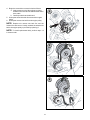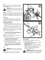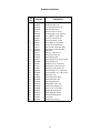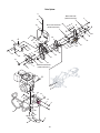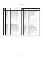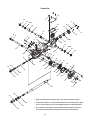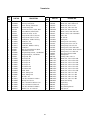
1
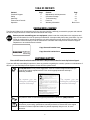
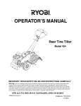
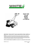
Operator’s Manual
Rear-tine Tiller
654J—Thoroughbred™
D077
49
AC
IMPORTANT: READ SAFETY RULES AND INSTRUCTIONS CAREFULLY
WARNING: This unit is equipped with an internal combustion engine and should not be used on or near any unimproved forest-covered, brush-covered or
grass-covered land unless the engine’s exhaust system is equipped with a spark arrester meeting applicable local or state laws (if any). If a spark arrester is used, it
should be maintained in effective working order by the operator. In the State of California the above is required by law (Section 4442 of the California Public
Resources Code). Other states may have similar laws. Federal laws apply on federal lands. A spark arrester for the muffler is available through your nearest engine
authorized service dealer or contact the service department, P.O. Box 361131 Cleveland, Ohio 44136-0019.
TROY-BILT LLC, P.O. BOX 361131 CLEVELAND, OHIO 44136-0019
PRINTED IN U.S.A.
FORM NO. 769-01146.fm
(3/17/2004)
TABLE OF CONTENTS
Content
Customer Support
Safety
Assembly
Features and Controls
Operation
Page
2
3
6
9
11
Content
Maintenance and Adjustments
Off-season Storage
Troubleshooting
Parts List
Warranty Information
Page
15
21
22
23
Back Cover
FINDING MODEL NUMBER
This Operator’s Manual is an important part of your new rear-tine tiller. It will help you assemble, prepare and maintain
the unit for best performance. Please read and understand what it says.
Before you start assembling your new equipment, please locate the model plate on the equipment and
copy the information from it in the space provided below. A sample model plate is also given below. You can
locate the model plate by standing behind the unit and looking down at rear surface of the tine shield. This
information will be necessary to use the manufacturer’s web site and/or help from the Customer Support
Department or an authorized service dealer.
Copy the model number here:
www.troybilt.com
Copy the serial number here:
TROY-BILT LLC
P. O. BOX 3 6 1 1 3 1
CLEVELAND, OH 44136
330-558-7220
1-800-520-5520
CUSTOMER SUPPORT
Please do NOT return the unit to the retailer from where it was purchased, without first contacting Customer Support.
If you have difficulty assembling this product or have any questions regarding the controls, operation or maintenance of
this unit, you can seek help from the experts. Choose from the options below:
Visit troy-bilt.com for many useful suggestions. Click on Customer Support button and you
will get the four options reproduced here. Click on the appropriate button and help is
immediately available.
The answer you are
looking for could be just
a mouse click away!
The answer you are
looking for could be just
a mouse click away!
If you prefer to reach a Customer Support Representative, please call 1(800) 520-5520.
Engine
Manual
The engine manufacturer is responsible for all engine-related issues with regards to
performance, power-rating, specifications, warranty and service. Please refer to the engine
manufacturer’s Owner’s/Operator’s Manual, packed separately with your unit, for more
information.
2
SECTION 1: IMPORTANT SAFE OPERATION PRACTICES
WARNING: This symbol points out important safety instructions which, if not followed, could endanger
the personal safety and/or property of yourself and others. Read and follow all instructions in this manual
before attempting to operate this machine. Failure to comply with these instructions may result in personal
injury. When you see this symbol—heed its warning.
DANGER: This machine was built to be operated according to the rules for safe operation in this manual. As with any type of power equipment, carelessness or error on the part of the operator can result in
serious injury. This machine is capable of amputating hands and feet and throwing objects. Failure to
observe the following safety instructions could result in serious injury or death.
California Proposition 65 Warning:
WARNING: Engine exhaust, some of its constituents, and certain vehicle components contain
or emit chemicals known to the State of California to cause cancer and birth defects or other
reproductive harm.
Training
b. The gas cap shall never be removed or fuel
added while the engine is running. Allow the
engine to cool for several minutes before
adding fuel.
c. Keep matches, cigarettes, cigars, pipes,
open flames, and sparks away from the fuel
tank and fuel container.
d. Fill fuel tank outdoors with extreme care.
Never fill fuel tank indoors. Use a funnel or
spout to prevent spillage.
e. Replace all fuel tank and container caps
securely.
f. If fuel is spilled, do not attempt to start the
engine, but move the machine away from the
area of spillage and avoid creating any
source of ignition until fuel vapors have
dissipated.
1. Carefully read this Operator’s Manual, the separate
Engine Owner/Operator’s Manual, and any other
literature you may receive. Be thoroughly familiar
with the controls and the proper use of the tiller and
its engine. Know how to stop the unit and
disengage the controls quickly.
2. Never allow children to operate the tiller. Never
allow adults to operate the tiller without proper
instruction.
3. Keep the area of operation clear of all persons,
particularly children and pets.
4. Keep in mind that the operator or user is
responsible for accidents or hazards occurring to
other people, their property, and themselves.
Preparation
1. Thoroughly inspect the area where the tiller is to be
used and remove all foreign objects.
2. Be sure all control levers are released before
starting the engine.
3. Do not operate the tiller without wearing adequate
outer garments. Avoid loose garments or jewelry
that could get caught in moving parts.
4. Do not operate the tiller when barefoot or wearing
sandals, sneakers, or light footwear. Wear
protective footwear that will improve footing on
slippery surfaces.
5. Do not till near underground electric cables,
telephone lines, pipes or hoses. If in doubt, contact
your telephone or utility company.
6. Never make adjustments when engine is running
(unless recommended by the Engine
manufacturer).
Operation
1. Do not put hands or feet near or under rotating
parts.
2. Exercise extreme caution when on or crossing
gravel drives, walks, or roads. Stay alert for hidden
hazards or traffic. Do not carry passengers.
3. After striking a foreign object, stop the engine,
thoroughly inspect the machine for any damage,
and repair the damage before restarting and
operating the machine.
4. Exercise caution to avoid slipping or falling.
5. If the unit should start to vibrate abnormally, stop the
engine and check immediately for the cause. Vibration
is generally a warning of trouble.
6. Stop the engine before unclogging the tines, or
when making any repairs, adjustments or
inspections.
7. Take all possible precautions when leaving the
machine unattended. Stop the engine and move
the Wheel Shift Lever to FORWARD.
WARNING: Handle fuel with care; it is highly flammable
and its vapors are explosive. Take the following precautions:
a. Store fuel in containers specifically designed
for this purpose.
3
20. Never operate the tiller without good visibility or
light.
21. Never operate the tiller if you are tired, or under the
influence of alcohol, drugs or medication.
22. Operators shall not tamper with the enginegovernor settings on the machine; the governor
controls the maximum safe operating speed to
protect the engine and all moving parts from
damage caused by overspeed. Authorized service
shall be sought if a problem exists.
23. Do not touch engine parts which may be hot from
operation. Let parts cool down
24. Please remember: You can always stop the tines
and wheels by releasing the Wheel Engagement
Handle.
25. Use extreme caution when reversing or pulling the
machine towards you.
26. Start the engine carefully according to instructions
and with feet well away from the tines.
27. Never pick up or carry a machine while the engine
is running.
8. Before cleaning, repairing, or inspecting, stop the
engine and make certain all moving parts have
stopped.
9. Always keep the tiller’s rear tine shield down.
10. Never use the tiller unless proper guards, plates, or
other safety protective devices are in place.
11. Do not run engine in an enclosed area. Engine
exhaust contains carbon monoxide gas, a deadly
poison that is odorless, colorless, and tasteless.
12. Keep children and pets away.
13. Be aware that the tiller may unexpectedly bounce
upward or jump backward if the tines should strike
extremely hard packed soil, frozen ground, or
buried obstacles like large stones, roots, or stumps.
If in doubt about the tilling conditions, always use
the following operating precautions to assist you in
maintaining control of the tiller:
a. Walk behind and to one side of the tiller,
using one hand on the handlebars. Relax
your arm, but use a secure hand grip.
b. Use slower engine speeds.
c. Clear the tilling area of all large stones, roots
and other debris.
d. Avoid using downward pressure on
handlebars. If need be, use slight upward
pressure to keep the tines from digging too
deeply.
e. Before contacting hard packed soil at the end
of a row, reduce engine speed and lift
handlebars to raise tines out of the soil.
f. In an emergency, stop tines and wheels by
releasing the Wheel Engagement Handle.
Do not attempt to restrain the tiller.
15. Do not overload the tiller’s capacity by attempting to
till too deeply at too fast a rate.
16. Never operate the tiller at high transport speeds on
slippery surfaces. Look behind and use care when
backing up.
17. Do not operate the tiller on a slope that is too steep
for safety. When on slopes, slow down and make
sure you have good footing. Never permit the tiller
to freewheel down slopes.
18. Never allow bystanders near the unit.
19. Only use attachments and accessories that are
approved by Troy-Bilt LLC.
Maintenance and Storage
1. Keep the tiller, attachments and accessories in safe
working condition.
2. Check all nuts, bolts, and screws at frequent
intervals for proper tightness to be sure the
equipment is in safe working condition.
3. Never store the tiller with fuel in the fuel tank inside
a building where ignition sources are present such
as hot water and space heaters, furnaces, clothes
dryers, stoves, electric motors, etc.). Allow engine
to cool before storing in any enclosure.
4. To reduce the chances of a fire hazard, keep the
engine free of grass, leaves, or excessive grease.
5. Store gasoline in a cool, well-ventilated area, safely
away from any spark- or flame-producing
equipment. Store gasoline in an approved
container, safely away from the reach of children.
6. Refer to the storage instructions in the
Maintenance section of this Manual and the
separate Engine Owner’s Manual for instructions if
the tiller is to be stored for an extended period.
7. If the fuel tank has to be drained, do this outdoors.
WARNING: YOUR RESPONSIBILITY Restrict the use of this power machine to persons who read,
understand and follow the warnings and instructions in this manual and on the machine.
4
SAFETY LABELS FOUND ON YOUR TILLER
WARNING
CAUTION: WATCH OUT FOR HANDS.
SLOWLY PULL STARTER ROPE BEYOND
BUMPER BEFORE STARTING.
Hot surfaces can
cause severe burns.
Do not touch
muffler or
adjacent areas.
S30647
I20943
WARNING
DEPTH
STAKE
WARNING
TO AVOID SERIOUS INJURY
1. READ THE OPERATOR'S MANUAL.
2. KNOW LOCATION AND FUNCTIONS
OF ALL CONTROLS.
3. KEEP ALL SAFETY DEVICES AND
SHIELDS IN PLACE AND WORKING.
4. NEVER ALLOW CHILDREN OR
UNINSTRUCTED ADULTS TO
OPERATE TILLER.
5. SHUT OFF ENGINE BEFORE
UNCLOGGING TINES OR MAKING
REPAIRS.
6. KEEP BYSTANDERS AWAY FROM
MACHINE.
7. KEEP AWAY FROM ROTATING
PARTS.
8. USE EXTREME CAUTION WHEN
REVERSING OR PULLING THE
MACHINE TOWARDS YOU.
SHALLOW /
TRANSPORT
POSITION
KEEP AWAY FROM
ROTATING TINES.
ROTATING TINES
WILL CAUSE INJURY.
DEEP /
FINAL TILLING
POSITION
5
SECTION 2: ASSEMBLING THE TILLER
1
2
NOTE: All references to the RIGHT or LEFT side of the
tiller are observed from operator’s position.
Tools Needed for Assembly
•
•
•
•
9/16” Wrench
7/16” Wrench or Nutdriver
Two 1/2” Wrenches
Phillips Screwdriver
(Handle Mount Bracket)
(Control Box)
(Threaded Cable Adjuster)
(Control Box)
3
Attaching the Handle
NOTE: Before beginning assembly, unfasten the cables
and lay them across the back of the tiller. Having an
assistant will ease completion of the following steps.
1. Remove the lower handle hardware (two hex screws,
two lock washers, one carriage screw & one handle
crank) from the tiller’s frame.
2. Position the handle mount bracket over the tiller
frame.
3. Align the handle mount bracket’s rear holes (either
upper or lower, depending on the operator’s height)
with the holes in the tiller frame. Insert the carriage
bolt through the holes from right to left and secure it
with the handle crank.
4. Align the handle mount bracket’s front holes with the
holes in the tiller frame. Using a 9/16” wrench, secure
the handle mount bracket to the tiller frame with the
hex screws and lock washers removed earlier.
4
6
5
6
Attaching the Control Box
5. Remove the four Phillips screws and lock nuts from
the control box plate.
6. Insert the ends of the two springs into the holes found
in the control levers located on the underside of the
handle panel.
7. Using a Phillips screwdriver and a 7/16” wrench,
secure the control box to the underside of the handle
panel with the four screws and lock nuts removed
earlier.
7
7
8
9
Attaching the Shift Cable
8. Place the shift lever in the forward position. Insert the
end of the shift cable into the hole in shift lever
located on the underside the handle panel.
9. Position the shift cable’s threaded adjuster in the slot
found on the shift lever mount bracket. (one nut below
the mount bracket and the flat washer, lock washer
and second nut above the mount bracket. See Inset).
10. Adjust the shift cable as follows:
a. Using a ½” wrench, thread the bottom nut
upward until the cable is taut.
b. Using a ½” wrench, thread the top nut
downward to secure the adjuster to the mount
bracket.
Position the shift cable (and three other cables)
against the left handle tube. Secure them to the
handle with the cable tie provided as shown in the
illustration at the top of the page.
10
B
A
Gas and Oil Fill-up
Gasoline
Service the engine with gasoline as instructed in the
separate Briggs & Stratton Operator/Owner Manual
packed with your tiller. Read instructions carefully.
Oil
IMPORTANT: Pour the entire contents of the provided oil
bottle into the engine’s oil fill.
8
SECTION 3: KNOW YOUR TILLER
Wheel Engagement Handle
Wheel Shift Lever
Tine Engagement Lever
Tine Direction Selector
Depth Regulator Lever
(Depth Stake)
Engine
Starter Handle
Handle Height Adjuster
Wheel Engagement Handle
Read this operator’s manual and safety rules before
operating your tiller. Compare the illustrations above with
your unit to familiarize yourself with the location of various
controls. Save this manual for future reference.
The wheel engagement handle
is located below the tiller’s
upper handle.
Engine
Closing the wheel engagement
handle with the wheel shift
lever in either FORWARD or
REVERSE will cause the tiller’s
wheels to drive.
See the Briggs & Stratton Owner/Operator manual
packed with your unit for the location and function of the
controls on the engine.
Starter Handle
The starter handle is located on the engine. Pull the
starter handle to start engine.
Releasing/Opening the wheel
engagement handle
automatically stops the tiller’s
wheels from driving
Wheel Shift Lever
The shift lever is located on the
right side of the handle panel
and has three positions,
FORWARD, NEUTRAL and
REVERSE. Place the wheel
shift lever in either FORWARD
or REVERSE before engaging
the drive handle. Always bring
the tiller to a complete stop
prior to moving the shift lever
from FORWARD to REVERSE
or vice-versa.
IMPORTANT: Never force the
shift lever. Doing so may result
in serious damage to the tiller’s
transmission.
NOTE: If the tiller’s tines and
wheels are engaged, releasing/
opening the wheel engagement
handle automatically stops
BOTH the tiller’s tines and the
tiller’s wheels from driving.
WHEEL DRIVE
F
N
R
I22311 AC
9
Tine Direction Selector
Tine Engagement Lever
The tine engagement lever is
located on the left side of the
handle panel and has two
positions, ON and OFF. To
engage the tines and begin
tilling, place the lever in the ON
position. To disengage the
tines, move the lever into the
OFF position.
The tine direction selector (found in the lower left area the
handle panel) is used to alternate tine rotation between
FRT mode (Forward Rotating Tines) to CRT mode
(Counter Rotating Tines).
•
Operate the tiller in CRT mode when tilling virgin
ground, sod or hard soil.
•
Operate the tiller in FRT mode when cultivating or
tilling soft ground or previously tilled soil.
NOTE: The tIne engagement
lever cannot be placed in the
ON position without first closing
the wheel engagement handle.
Also, the tIne engagement
lever cannot be placed in the
ON position unless the wheel
shift lever is in the FORWARD
position. Refer to Safety Interlock
System on Page 11.
IMPORTANT: When operating the tiller in FRT mode,
always lower the depth regulator lever (for a shallower
tilling depth).
ON
TINES
Depth Regulator Lever
The highest notch (lever all the
way down) raises the tines
approximately 1/2-inch off the
ground. This “travel” position
allows the tiller to be moved
without the tines digging into
the ground.
OFF
SHALLOW /
Handle Height Adjuster
TRANSPORT
The handle mount bracket can be adjusted downward (for
shorter operators) or upward (for taller operators) using
the handle height adjuster. Align the handle mount
bracket’s rear holes with the holes in the tiller frame. Insert
the carriage bolt through the holes from right to left and
secure it with the handle crank.
POSITION
Moving the lever up increases
the tilling depth. The lowest
notch allows a tilling depth of
approximately six to eight
inches, depending on soil
conditions.
DEEP /
FINAL TILLING
POSITION
10
SECTION 4: OPERATING YOUR TILLER
WARNING: Read, understand, and follow all
7. Set the tilling depth by moving the depth regulator
lever rearward, then either up or down into the
desired depth setting. Refer to Depth Regulator Lever on
Page 10.
instructions and warnings on the machine, in
this manual and the Briggs & Stratton Owner/
Operator manual packed with your unit before
operating the tiler.
NOTE: Move the Depth Regulator Lever into the “travel”
position (lever all the way down) so that the tines clear the
ground. Use this position when practicing with or
transporting the tiller. When you are ready to begin tilling,
move the Depth Regulator Lever into the desired depth
setting. Refer to Depth Regulator Lever on Page 10.
Safety Interlock System
IMPORTANT:Your tiller is equipped with an interlock
system for the protection of the operator. If the interlock
system should ever malfunction, do not operate the tiller.
Contact an authorized service dealer.
•
•
•
•
•
Starting Engine
The Wheel Engagement Handle must be in the closed
position in order to engage the tines
The Wheel Shift Lever must be in the FORWARD
position in order to engage the tines.
The Wheel Shift Lever cannot be moved out of the
FORWARD position unless the Tine Engagement
Lever is in the OFF position.
The tines will automatically stop if the operator
releases the Wheel Engagement Handle.
The wheels will automatically stop if the operator
releases the Wheel Engagement Handle.
•
Move choke control lever to CHOKE position.
WARNING: Do not operate the tiller if the
NOTE: A warm engine may not require choking.
interlock system is malfunctioning. This system
was designed for your safety and protection.
•
Move throttle control lever to FAST (rabbit) position.
•
Grasp the starter handle and pull the rope out slowly
until resistance is felt. When it becomes slightly
harder to pull the rope, slowly allow the rope to recoil.
Then pull rope with a rapid, continuous, full arm
stroke. Keep a firm grip on starter handle.
Maintain a grip on the starter handle and allow the
rope to recoil slowly.
Repeat the previous steps until engine starts. When
engine starts, move choke control gradually toward
the RUN position until the engine is running smoothly.
Pre-Start Checklist
Do the following before starting the engine.
1. Check unit for loose or missing hardware. Service as
required.
2. Check motor oil level. Refer to separate Briggs &
Stratton Operator/Owner Manual.
3. Check that all safety guards and covers are in place.
4. Check air cleaner and engine cooling system. Refer
to separate Briggs & Stratton Operator/Owner
Manual.
5. Select a tine direction (Refer to Tine Direction Selector
on page 10).
6. Fill the fuel tank with gasoline as instructed in the
separate Briggs & Stratton Operator/Owner Manual
packed with your tiller. Read instructions carefully.
•
•
WARNING: Gasoline is highly flammable and
its vapors are explosive. Follow gasoline safety
rules found on Page 3 in this manual, and in the
separate Briggs & Stratton Operator/Owner
Manual. Failure to follow gasoline safety
instructions can result in serious personal injury
and property damage.
WARNING: Never run the engine indoors or
in a poorly ventilated area. Engine exhaust
contains carbon monoxide, an odorless and
deadly gas.
11
Stopping Engine
•
4. For forward motion of the wheels and power to the
tines:
a. Place the tine direction selector in either the
CRT position or FRT position.
Move throttle control lever to STOP position. See
Figure 1.
NOTE: Operate the tiller in CRT mode when tilling virgin
ground, sod or hard soil. Operate the tiller in FRT mode
when cultivating or tilling soft ground or previously tilled
soil.
b. Place the wheel shift lever in the FORWARD
position.
c. Close the wheel engagement handle against
the handlebar to cause the wheels to drive.
d. Place the tine engagement lever in the ON
position to begin tilling.
Figure 1
CAUTION: Never stop the engine by moving
the choke lever into the CHOKE position.
Backfire, fire or engine damage could result.
IMPORTANT: To stop the wheels and tines, release the
wheel engagement handle.
WARNING: Do not push down on the
handlebar to try to make the tiller till more
deeply. Doing so prevents the wheels from
holding the tiller back and can allow the tines (in
CRT mode) to rapidly propel the tiller backward
toward the operator, which could result in loss of
control, property damage, or personal injury.
Operating the Tiller
WARNING: Before tilling new ground,
contact your telephone and utilities company to
inquire if underground lines are on the property.
The following pages provide guidelines to using your tiller
effectively and safely in various gardening applications.
Be sure to read Tilling Tips & Techniques in this Section
before you actually put the tines into the soil.
•
1. Follow the Pre-Start Checklist on page 11. Be sure that
the wheel shift lever is in the NEUTRAL position.
2. Start the engine and allow it to warm up for a few
minutes. Move the throttle control into the FAST
speed setting.
•
•
•
IMPORTANT: Always operate the tiller with the throttle in
the FAST (rabbit) position.
3. For forward or reverse motion of the wheels and no
power to the tines:
a. Place the tine engagement lever in the OFF
position.
b. Place the wheel shift lever in either the
FORWARD position or REVERSE position.
As the tiller moves forward, relax and let the wheels
pull the unit along while the tines dig.
Walk behind, and a little to one side of the tiller.
Use a light but secure grip with one hand on the
handlebars, but keep your arm loose.
Let the tiller move ahead at its own pace. Do not push
down on the handlebar in an attempt to force the tiller
to dig deeper. If necessary, stop the tiller, turn off the
engine and reposition the depth regulator lever to
adjust tilling depth before restarting and operating the
tiller.
5. To turn the tiller around:
a. Practice turning in a level, open area with the
tines not engaged.
b. To start a turn, carefully raise the handlebar
until the engine and tines are balanced over the
wheels.
c. With the tiller balanced, push sideways on the
handlebar to move the tiller in the direction of
the turn. After completing the turn, slowly lower
the tines into the soil.
NOTE: If you encounter difficulty repositioning the
wheel shift lever from FORWARD or REVERSE into
NEUTRAL or vice-versa, gently rock the tiller (slightly
push-and-pull the handlebar forward and backward) prior
to moving the wheel shift lever. Doing so will help fully
disengage the transmission’s internal drive clutch.
Stopping the Tiller and Engine
1. To stop the wheels and tines, release /open the wheel
engagement handle.
2. To stop the engine, move the engine throttle lever to
STOP. Refer to Figure 1.
c. Close the wheel engagement handle against
the handlebar to cause the wheels to drive. To
stop the wheels, release the wheel
engagement handle.
12
TILLING TIPS & TECHNIQUES
Tilling Depths
• This tiller can be operated in CRT (counter-rotating tine) mode. As the wheels pull forward,
the tines rotate backward. This creates an “uppercut” tine action which digs deeply, uprooting
soil and weeds. Don’t overload the engine when operating in CRT mode, but dig as deeply as
possible on each pass. On later passes, the wheels may tend to spin in the soft dirt. Help them
along by lifting up slightly on the handlebar (or simply switch to operating in FRT mode).
WARNING: Before
tilling, contact your
telephone or utilities
company and inquire if
• Avoid the temptation to push down on the handlebar in an attempt to force the tiller to dig
underground equipment or
deeper. Doing so takes the weight off the powered wheels, causing them to lose traction.
lines are used on your
Without the wheels to hold the tiller back, the tines will attempt to propel the tiller backward,
property. Do not till near
towards the operator. (Sometimes, slight downward pressure on the handlebar will help get
buried electric cables,
through a particularly tough section of sod or unbroken ground, but in most cases this won’t
telephone lines, pipes or
be necessary.)
hoses.
• When cultivating (breaking up surface soil around plants to destroy weeds), adjust the tines to dig only 1" to 2" deep. Using shallow tilling
depths helps prevent injury to plants whose roots often grow close to the surface. If needed, lift up on the handlebar slightly to prevent
the tines from digging too deeply. (Cultivating on a regular basis not only eliminates weeds, it also loosens and aerates the soil for better
moisture absorption and faster plant growth.) Watering the garden area a few days prior to tilling will make tilling easier, as will letting
the newly worked soil set for a day or two before making a final, deep tilling pass.
Choosing Correct Tine Depth & Rotation
With experience, you will find the “just right” tilling depth and tine rotation combination
that is best for your garden under specific conditions.
• Operate the tiller in CRT mode when tilling virgin ground, sod or hard soil.
• Operate the tiller in FRT mode when cultivating or tilling soft ground or previously tilled soil.
IMPORTANT: When operating the tiller in FRT mode, always lower the depth regulator lever (for a shallower tilling depth).
Let the Tiller Do the Work
Avoid Making Footprints
While tilling, relax and let the wheels pull the
tiller along while the tines do the digging.
Walk on the side that is not yet finished (to
avoid making footprints in the freshly tilled
soil) and lightly, but securely grip the handlebar with just one hand. Always operate
the tiller with the throttle in the FAST (rabbit) position.
Avoid Tilling Soggy, Wet Soil
Whenever possible, walk on the untilled
side of the unit to avoid making footprints in
your freshly tilled or cultivated soil. Footprints cause soil compaction that can hamper root penetration and contribute to soil
erosion. They can also “plant” unwanted
weed seeds back into the freshly tilled
ground.
Tilling wet soil often results in large, hard
clumps of soil that can interfere with planting. If time permits, wait a day or two after
heavy rains to allow the soil to dry before
tilling. Test soil by squeezing it into a ball. If
it compresses too easily, it is too wet to till.
Preparing Seedbeds
• When preparing a seedbed, go over the same path twice in the first row, then overlap one-half the tiller width on the rest of the passes (see Seedbed 1). When finished in one direction, make a second pass at a right angle (Seedbed 2). Overlap
each pass for best results (in very hard ground, it may take three or four passes to
thoroughly pulverize the soil.)
Seedbed 1
Cultivating
• If the garden size will not permit lengthwise and then crosswise tilling, then overlap the first passes by one-half a tiller
width, followed by successive passes
1
at one-quarter width (see Seedbed
2
3).
3
Seedbed 3
13
With planning, you can
allow enough room
between rows to cultivate.
Leave room for the hood
width, plus enough extra
room for future plant
growth.
Seedbed 2
TILLING TIPS & TECHNIQUES (CON’T)
Tilling On Slopes
Read the following recommendations before tilling on slopes:
If you must garden on a moderate slope, please follow two very important guidelines:
1. Till only on moderate slopes, never on steep ground where footing is difficult (review safety rules in Section 1: Safety of this manual).
2. We recommend tilling up and down slopes rather than terracing. Tilling vertically on a
slope allows maximum planting area and also leaves room for cultivating.
IMPORTANT: When tilling on slopes, be sure the correct oil level is maintained in the engine
(check every one-half hour of operation). The incline of the slope will cause the oil to gravitate
away from its normal level and this can starve engine parts of required lubrication. Keep the
motor oil level at the full point at all times!
WARNING: Do not
operate tiller on a slope too
steep for safe operation. Till
slowly and be sure you have
good footing. Never permit
tiller to freewheel down
slopes. Failure to follow this
warning could result in
personal injury.
Tilling Up and Down Slopes (Vertical Tilling)
• To keep soil erosion to a minimum, be sure to add enough organic matter to the soil so that it has good moisture-holding texture and try
to avoid leaving footprints or wheel marks.
• When tilling vertically, try to make the first pass uphill as the tiller digs more deeply going uphill than it does downhill. In soft soil or weeds,
you may have to lift the handlebars slightly while going uphill. When going downhill, overlap the first pass by about one-half the width of
the tiller.
Clearing the Tines
The tines have a self-clearing action which eliminates most tangling of debris in the
tines. However, occasionally dry grass, stringy stalks or tough vines may become tangled. Follow these procedures to help avoid tangling and to clean the tines, if necessary.
• To reduce tangling, set the depth regulator deep enough to get maximum “chopping”
action as the tines chop the material against the ground. Also, try to till under crop
residues or cover crops while they are green, moist and tender.
• While tilling, try swaying the handlebars from side to side (about 6" to 12"). This
“fishtailing” action often clears the tines of debris.
• If tangling occurs, lift the tines out of the soil and run the tiller in reverse for a few
feet. This reversing action should unwind a good deal of debris.
Loading and Unloading the Tiller
WARNING: Loading and
unloading the tiller into a vehicle is
potentially hazardous. Doing so is
NOT recommend unless
absolutely necessary, as this could
result in personal injury or
property damage. However, if you
must load or unload the tiller,
follow the guidelines given next.
• Before loading or unloading, stop the engine,
wait for all parts to stop moving and allow the
engine and muffler cool.
• The tiller is too heavy and bulky to lift safely
by one person. Two or more people should
share the load.
• It may be necessary to remove the debris by hand (a
pocket knife will help you to cut away the material).
• Use sturdy ramps and manually (engine shut
off) roll the tiller into and out of the vehicle.
Two or more people are needed to do this.
• The ramps must be strong enough to support
the combined weight of the tiller and any handlers. The ramps should provide good traction
to prevent slipping; they should have side rails
to guide the tiller along the ramps; and they
should have a locking device to secure them to
the vehicle.
• The handlers should wear sturdy footwear that
will help to prevent slipping.
• Position the loading vehicle so that the ramp
angle is as flat as possible (the less incline to
the ramp, the better). Turn the vehicle’s engine
off and apply its parking brake.
• When going up ramps, stand in the normal
operating position and push the tiller ahead of
you. Have a person at each side to turn the
wheels.
14
WARNING: Before clearing the
tines by hand, stop the engine, allow all
moving parts to stop. Failure to follow
this warning could result in personal
injury.
• When going down ramps, walk backward
with the tiller following you. Keep alert for any
obstacles behind you. Position a person at
each wheel to control the speed of the tiller.
Never go down ramps tiller-first, as the tiller
could tip forward.
• Place wooden blocks on the downhill side of
the wheels if you need to stop the tiller from
rolling down the ramp. Also, use the blocks to
temporarily keep the tiller in place on the
ramps (if necessary), and to chock the wheels
in place after the tiller is in the vehicle.
• After loading the tiller, prevent it from rolling
by placing the wheel shift lever in the FORWARD position. Chock the wheels with blocks
and securely tie the tiller down.
SECTION 5: MAINTENANCE AND ADJUSTMENTS
Cleaning the Tiller
WARNING:
Before
performing
any
maintenance, or repairs, turn the engine off and
allow it to cool, move the tiller to a level surface,
place the wheel shift lever in the FORWARD
position and chock the tiller’s wheels.
Any fuel or oil spilled on the machine should be wiped off
promptly. Do NOT allow mud and debris to accumulate
around the cooling fins of the engine or on any other part
of the machine, especially around the bottom frame
cover, under the belt cover, around the belts, pulleys,
shifter linkage and other moving parts.
MAINTENANCE SCHEDULE
PROCEDURE
Check motor oil level
Clean engine
Check drive belt tension
Check nuts and bolts
Change motor oil
Lubricate tiller
Service foam pre-cleaner air filter
Service paper air filter
Check gear oil level in transmission
Check tines for wear
Check air pressure in tires
Service spark plug
Clean tiller
NOTES
2, 3
2, 7
1, 4
1, 4
1, 4, 6
4, 8
7
7
1, 5
5
5
7
8
•
•
Remove the belt cover at least once a season and
clean any debris away from belts and pulleys
Clean around the bottom frame cover and the
underside of the tine shield and with a garden hose
after each use.
IMPORTANT:Thoroughly dry the tine shield and entire
machine after each cleaning. Lubricate any pivot points
and all axles to inhibit rust from forming and metal parts
from corroding and seizing over time.
Lubrication
WARNING:
Before
performing
any
maintenance or repairs, turn the engine off and
allow it to cool, move the tiller to a level surface,
place the wheel shift lever in the FORWARD
position and chock the tiller’s wheels.
NOTES
1.
2.
3.
4.
5.
6.
7.
After first 2 hours of break-in operation.
Before each use.
Every 5 operating hours.
Every 10 operating hours.
Every 30 operating hours.
Change more frequently in dusty or dirty conditions.
See Engine Owner’s Manual for service
recommendations.
8. After each use.
Engine
Lubricate the engine with motor oil as instructed in the
Briggs & Stratton Operator/Owner Manual packed with
your unit.
Pivot Points & Linkage
Lubricate all the pivot points on the depth regulator lever,
handle height adjuster and levers (found on underside of
the handle panel) at least once a season with light oil.
Remove the belt cover at least once a season and clean
any debris away from belts and pulleys before lubricating
pivot points on pulley brackets with a light oil.
Engine
Check engine oil level before each use as instructed in
the Briggs & Stratton Operator/Owner Manual packed
with your unit. Follow the instructions carefully.
Engine Oil
Axles (Wheel & Tine)
Refer to the Briggs & Stratton Operator/Owner Manual
packed with your unit for instruction on changing the
engine oil and for information regarding the quantity and
proper weight of motor oil.
Remove each wheel and tine holder from its axle at least
once a season and before extended storage. Clean each
axle and lubricate with an all-purpose grease before
reinstalling each wheel and tine holder.
Air Cleaner
Service the pre-cleaner, if so equipped, and cartridge/air
cleaner element as instructed in the Briggs & Stratton
Operator/Owner Manual packed with your unit.
Transmission
Spark Plugs
Before each use, check your tiller for signs of an oil leak—
usually a dirty, oily accumulation either on the unit or on
the floor where it has been parked.
Checking for Oil Leaks
The spark plug should be cleaned and the gap reset once
a season. Refer to the Briggs & Stratton Operator/Owner
Manual for correct plug type and gap specifications.
A little seepage around a cover or oil seal is usually not a
cause for alarm. If a small puddle forms below the tiller
within hours, however, then service is required.
15
Ignoring a leak can result in severe transmission damage.
If a cover leaks, try tightening any loose screws or bolts. If
the fasteners are tight, a new gasket or oil seal may be
required. If the leak is from around a shaft and oil seal, the
oil seal probably needs to be replaced. See an authorized
service dealer.
Changing Oil
Oil level should be visually checked if evidence of a leak
is present. Oil should be added in such cases, but
changing the transmission oil as part of general
maintenance is unnecessary
Checking Oil Level
Check the oil level after every 30 hours of operation and
whenever there is any oil leakage.
IMPORTANT:Never operate the tiller if the transmission is
Figure 3
low on oil.
IMPORTANT: If loosened or removed, a sealant (Loctite
1. Position the tiller on a level surface.
2. Remove the fill plug found on the front of the
transmission. See Figure 2.
Ultra Black™ Silicone 5900) must be applied to these
screws before they can be reused without risking the loss
of transmission oil.
Adjustments
WARNING:
Before
performing
any
maintenance or repairs, turn the engine off and
allow it to cool, move the tiller to a level surface,
place the wheel shift lever in the FORWARD
position and chock the tiller’s wheels.
Handle Height
The handle mount bracket can be adjusted downward (for
shorter operators) or upward (for taller operators) using
the handle height adjuster.
•
Figure 2
•
3. The drive shaft (visible through the transmission plug
opening) should be half-submerged. If necessary,
slowly add SAE 85W140 oil until the drive shaft is
approximately half-submerged.
•
IMPORTANT: Do NOT add oil to the top of the
Unthread the handle crank and remove the carriage
bolt which secures handle mount bracket to the tiller
frame. See Figure 4.
Pivot the handlebar upward or downward to align the
handle mount bracket’s rear holes (either upper or
lower) with the holes in the tiller frame.
Re-insert the carriage bolt through the holes from
right to left and secure it with the handle crank.
transmission housing. Do NOT fully submerge the drive
shaft with oil. Doing so will not allow for oil expansion and
may result in serious damage to the transmission .
Checking Hardware
Check the unit for loose or missing hardware after every
10 operating hours. Loose or missing hardware can lead
to equipment failure, poor performance, or oil leaks.
Be sure to check the three mounting screws located on
each of two end caps found at the rear of the transmission
(See Figure 3). Lift the tine flap to service those screws.
Figure 4
16
Shift Cable
If the tiller’s wheels do not “freewheel” when the wheel
shift lever is in the NEUTRAL position, the shift cable is in
need of adjustment. Refer to Step 10 on Page 8 for
detailed instructions.
1
Tine Engagement Cables
If the tines fail to drive when the tine engagement lever is
placed in the ON position, or if the tines fail to stop when
the tine engagement lever is placed in the OFF position,
DO NOT OPERATE THE TILLER. The tine engagement
c able is in need of adjustment.
1. Remove the belt cover by removing the top screw and
washer (and loosening the side screws) which secure
it.
2. To adjust the cable:
a. Loosen the inside hex nut found on the cable
adjuster.
b. Loosen the outside hex nut found on the cable
adjuster.
c. Grasp the metal cable housing and gently pull
outward to take up slack (usually no more than
1/4-inch) in the cable before retightening both
hex nuts loosened earlier.
2
b
a
c
Wheel Engagement Cable
1. Adjust the wheel engagement cable as follows:
a. Using a ½” wrench, loosen the upper hex nut
found on the cable adjuster.
b. Loosen the lower hex nut found on the cable
adjuster.
c. Grasp the metal cable housing and gently pull
outward to take up slack (usually no more than
1/4-inch) in the cable before retightening both
hex nuts loosened earlier.
a
1
a
b
c
17
b
SECTION 6: SERVICE
1
2
Changing the Belts
WARNING: Position the tiller on flat, level
surface, chock the wheels, shut the engine off
and allow it to cool before removing the belt(s).
All belts on your tiller are subject to wear and should be
replaced if any signs of wear are present.
IMPORTANT:The belts found on your tiller are specially
designed to engage and disengage safely. A substitute
(non-OEM) belt can be dangerous by not disengaging
completely. For a proper working machine, always use
factory approved belts.
a
3
To replace the belts on your tiller, proceed as follows:
Tine Drive Belts
c
1. Remove the belt cover by removing the top screw and
washer (and loosening the side screws) which secure
it.
2. Remove the belt keeper rod by removing the screw
and washers which secure it.
3. Remove the forward tine belt as follows:
a. Loosen, but do not remove, the hex nuts which
secure the two idler pulleys.
b. Unloop the belt from around the bottom pulley.
c. Unloop the belt from around the two idler
pulleys.
a
b
18
4. Begin the removal the reverse tine belt as follows:
a. Apply pressure on the idler pulleys to relieve
tension on the reverse tine cable and the wheel
drive cable.
b. Carefully unhook each cable-end.
5. Unloop the wheel drive belt from around the engine
pulley.
6. Unloop the reverse tine belt from the engine pulley.
4
NOTE: Replace the reverse tine belt first and the
forward tine belt second. Lastly, reattach the wheel drive
belt to the engine pulley or proceed by replacing it.
a
b
NOTE: To install replacement belts, perform steps 1-6
in reverse order.
5
6
19
1
2
Wheel Drive Belt
3
NOTE: The wheel drive belt is under the least amount of
a
Front View
load and will wear at a slower rate. It may not be
necessary to replace the wheel drive belt as often as the
tine belts. Inspect the belt and read the following steps
before proceeding.
b
Rear View
1. Remove the left wheel by removing the cotter pin and
clevis pin which secure it. Use a jack stand or wood
blocks to secure the left wheel axle and stabilize the
tiller.
2. Remove the upper two screws which secure the
bottom frame cover and pivot it downward.
3. Remove the wheel drive belt from around the lower
idler pulley as follows:
a. Loosen, but do not remove, the hex bolt which
secures the lower idler pulley.
b. Unloop the belt from around the lower idler
pulley and transmission pulley.
4. Remove the wheel drive belt from around the upper
idler pulley as follows:
a. Carefully remove the small spring from the
upper pulley’s idler bracket.
b. Gently pry the belt keeper tab upward with a
flathead screwdriver.
c. Carefully unloop the wheel drive belt from
around the upper idler pulley.
a
b
NOTE: To install a replacement belt, perform steps 1-4
in reverse order.
4
c
a
20
b
Tines
The tines will wear with use and should be inspected at
the beginning of each tilling season and after every 30
operating hours.
1-2
WARNING: Position the tiller on flat, level
surface, chock the wheels, shut the engine off
and allow it to cool before inspecting or
removing the tines.
NOTE: The tine shield end-covers (left side and right
side) must be removed in order to take off either a single
tine holder or individual tines. The end-covers are
secured to the tine shield housing with three hex nuts
each.
Tine Inspection
With use, the tines will become shorter, narrower and
pointed. Badly worn tines will result in a loss of tilling
depth and reduced effectiveness when chopping up and
turning under organic matter.
Removing and Installing Tines
3-6
1. Use a pair of pliers to remove the internal cotter pin
and clevis pin that secures each tine holder to the tine
shaft.
2. Use a rubber mallet to tap the tine holder free of the
tine axle and slide the tine assembly off the tine axle.
NOTE: The tine shield and handlebar are not shown for
clarity. It is NOT necessary to remove the tine shield and
handlebar to service the tiller tines.
3. Use a 9/16" socket wrench, and a 9/16" box wrench
to remove the hex nuts, washer(s) and bolts that
secure each tine to the tine holder.
NOTE: It is recommended that tines be changed one at
a time for ease in reassembling
4. Install a replacement tine in the exact orientation as
the tine just removed. Note the location and
orientation of washers were applicable.
5. Repeat Steps 1-through-4 above to remove the other
tine assembly and individual tines.
6. When reinstalling the tine assemblies onto the tine
axles, be sure to first remove any rust, uneven spots
or burrs from the tine axle, using fine sandpaper.
Then grease the tine axle before reinstalling the tine
assemblies.
Off-season Storage
When the tiller won’t be used for extended periods,
prepare it for storage as follows:
•
•
•
Tires
WARNING: Never exceed the maximum
•
inflation pressure shown on the sidewall of the
tire.
Clean and lubricate the tiller as instructed in Section 7:
MAINTAINING YOUR TILLER on page 15.
Check for loose parts and hardware (see Checking
Hardware on page 16).
Protect the engine by performing the engine storage
instructions in the separate Briggs & Stratton
Operator/Owner Manual packed with your tiller.
Store unit in a clean, dry area.
WARNING: Never store the machine or fuel
container indoors where there is an open flame,
spark or pilot light such as on water heater,
furnace, clothes dryer or other gas appliance.
Refer to the tire sidewall for exact tire manufacturer’s
recommended or maximum psi. Do not overinflate.
21
TROUBLESHOOTING
PROBLEM
Engine does not start
POSSIBLE CAUSE
CORRECTION
1.
Spark plug wire disconnected.
1.
Reconnect wire. (See Engine Owner’s Manual)
2.
Engine Throttle Control Lever incorrectly set.
2.
Put lever in START position.
3.
Fuel tank empty.
3.
Add fuel.
4.
Choke control in incorrect position.
4.
See Page 11, Starting the Engine.
5.
Stale gasoline.
5.
Drain fuel and add fresh fuel.
6.
Dirty air filter.
6.
Clean or replace filter.
7.
Fouled or incorrectly gapped spark plug.
7.
Inspect spark plug (see Engine Owner’s Manual)
8.
Carburetor out of adjustment.
8.
See Engine Service Dealer.
9.
Misadjusted throttle control.
9.
See Engine Service Dealer
10. Dirt or water in fuel tank.
10. See Engine Service Dealer.
1.
Fouled or incorrectly gapped spark plug.
1.
Inspect spark plug (see Engine Owner’s Manual).
2.
Dirty air filter(s).
2.
Clean or replace (see Engine Owner’s Manual).
3.
Carburetor out of adjustment.
3.
See Engine Service Dealer.
4.
Stale gasoline.
4.
Replace with fresh gasoline.
5.
Dirt or water in fuel tank.
5.
See Engine Service Dealer.
6.
Engine cooling system clogged.
6.
Clean air cooling system (see Engine Owner’s Manual).
1.
Engine cooling system clogged.
1.
Clean air cooling area (see Engine Owner’s Manual).
2.
Carburetor out of adjustment.
2.
See Engine Service Dealer.
3.
Oil level is low.
3.
Check oil level (see Engine Owner’s Manual).
Engine does not shut off
1.
Misadjusted throttle control.
1.
See Engine Owner’s Manual or Engine Service Dealer.
Wheels and Tines will not turn
1.
Improper use of controls.
1.
Review Section 3 and Section 4.
2.
Worn, Broken or misadjusted belt(s).
2.
Review Section 5 to adjust or replace belt.
3.
Internal transmission wear or damage.
3.
Contact local dealer or the factory.
4.
Bolt and key loose in transmission pulley.
4.
Tighten bolt. Check that key is in place.
1.
Wheel Drive Pins not in axle.
1.
Replace Wheel Drive Pins
2.
Internal transmission wear or damage.
2.
Contact authorized service dealer
3.
Wheel drive belt slipping
3.
Review Section 5 to adjust wheel drive cable
4.
Worn, Broken or misadjusted belt.
4.
Review Section 5 to adjust or replace belt.
5.
Wheel drive cable broken
5.
Contact authorized service dealer.
1.
Tine holder mounting hardware missing.
1.
Replace hardware.
2.
Internal transmission wear or damage.
2.
Contact local Dealer or the Factory.
1.
Worn tines.
1.
See “Tines” (Section 5).
2.
Improper Depth Regulator setting.
2.
See “Tilling Tips & Techniques,” Section 4.
3.
Belt(s) slipping.
3.
See Section 5 to adjust tine cable(s) or replace belt.
Engine runs poorly.
Engine overheats.
Tines turn, but wheels don’t.
Wheels Turn, but Tines Don’t.
Poor tilling performance.
22
SECTION 7: MODEL 654J PARTS LIST
Wheels and Tines
7
8
12
16
15
6
5
3
2
4
17
18
11
10
1
13
9
14
REF
NO.
1
2
3
4
5
6
7
8
9
PART NO.
642-04015
712-3054
736-0169
736-0208
736-0253
738-0688
738-0689
742-0305
618-04120
REF
NO.
DESCRIPTION
Adapter Assembly, Tine
Nut, 3/8-24, Hex, Lock
Washer, Lock, 3/8, Regular Duty
Washer, Flat, .51 x 1.5 x .07
Washer, Bell, .525 x 1.00 x.050
Screw, Shoulder 1/2 Dia x .325
Screw, Shoulder 1/2 Dia x .180, 3/8-2
Tine, Articulating
Transmission Assembly, Dual Direction
10
11
12
13
14
15
16
17
18
23
PART NO.
710-1194
712-0161
746-04150
634-0240
634-0241
711-1017
714-0104
714-0149B
711-0415
DESCRIPTION
Screw, Machine, #10-24, 1.00, Gr5
Nut, Hex Lock, #10-24, Gr2, Nylon
Cable, Shift, Wheel
Wheel, Complete, 14 x 4.5 x 6, RH, Gray
Wheel, Complete, 14 x 4.5 x 6, LH, Gray
Pin, Clevis, .250 x 1.53
Pin, Cotter, .072 Dia. x 1.13 Lg
Internal Cotter Pin
Pin, Clevis, 3/8, 1.75
Handlebar and Controls
22
3
26
25
C
12
2
36
B
22
1
13
38
A
13
11
23
13
B
22
2
A
18
8
10
D
17
10
C
37
14
20
D
17
9
26
13
30
22
27
32 31
34
16
19
15
14
4
6
13
29
28
20
5
35
24
13
13
Handlebar and Controls
REF
NO.
1
2
3
4
5
6
7
8
9
10
11
12
13
14
15
16
17
18
19
20
22
23
25
26
27
28
29
30
31
32
33
34
35
36
37
38
PART NO.
647-04026
649-04014
686-04038
686-04040
710-3119
710-04198
710-04202
710-0501
710-0539
710-0946
710-1656
712-0116
712-0324
720-04039
725-0157
731-04616
731-04644
732-0193
732-0590A
736-0105
736-3012
736-3052
738-04072
738-04088
741-0862
746-04098
746-04099
746-04100
746-04107
746-04108
750-04226
786-04162
786-04199
786-04212
786-04213
786-04214
DESCRIPTION
Bail Assembly, Control, Wheel
Handle Assembly, Loop
Lever Assembly, Control, Tine
Lever Assembly, Pivot
Hex Screw, 3/8-16, .75, Gr5
Screw, Carriage, 3/8-16, 6.00, Gr5
Screw, Machine, 1/4-20, 2.500
Hex Screw, 1/4-20, 2.0, Gr5
Hex Screw, 3/8-24, 1.75, Gr5
Screw, Machine, 1/4-20, 0.625
Hex Screw, 1/4-20, 6.00, Gr5
Nut, Jam Lock, 3/8-24, Gr5, Nylon
Nut, Hex Lock, 1/4-20, Gr8, Nylon
Knob, Shift
Cable, Tie, 3/16 x .05 x 7.4
Box, Control, Select, Tine
Block, Mounting, Bail
Spring, Compression, .39x.60 x .88 Lg
Spring, Compression
Washer, Bell, .375 x .870 x .063
Washer, Wave, .390 x .625 x .016
Washer, Flat, .406 x 1.00 x .105
Screw, Shoulder, .373 x .830, 1/4-20
Screw, Shoulder, .373 x .180 x 1/4-20
Ball, Detent, .250
Cable, Clutch, Drive, Wheel
Cable, Clutch, Drive, Tine
Cable, Engagement, Tine
Block, Control, Select, Tine
Block, Control, Engage, Tine
Spacer, .270 x .375 x 5.00 Lg
Bracket, Mounting, Control
Crank, Adjustment, Handle
Bracket, Mounting, Control
Lever, Shift
Bracket, Pivot, Interlock
25
Drive System
6
Wheel Clutch Cable
(Shown for Reference)
8
23
25
15
Reverse Tine Clutch Cable
(Shown for Reference)
23
6
20
22
11
G
42
E
A
46
38
11
27
18
C
11
2
18
10
38
5
3
40
28
38
31
34
12
Forward Tine Clutch Cable
(Shown for Reference)
1
7
14
B
G
F
48
9
43
11
17
18
51
18
49
9
D
C
50
24
29
11
B
21
32
44
30
36
41
16
F
D
19
23
E
26
35
4
A
37
7
47
4
45
26
18
44
21
39
13
33
21
Drive System
REF
NO.
1
2
3
4
5
6
7
8
9
10
11
12
13
14
15
16
17
18
19
20
21
22
23
24
25
26
PART NO.
686-04034
710-0117
710-0378
710-0599
710-0624
710-0642
710-0723
710-0902
710-3008
710-3144
712-0266
712-0700
712-0702
714-04032
731-04590
732-0320
732-0545
736-0119
736-0185
736-0329
736-0362
736-0452
736-3090
1918749
747-04191
750-04221
REF
NO.
DESCRIPTION
Bracket Assembly, Clutch
Hex Screw, 5/16-24, 1.00, Gr5
Hex Screw, 5/16-18, 2.50, Gr5
Screw, Self-tapping, 1/4-20, 0.500
Hex Screw, 5/16-24, 1.50, Gr5
Screw, Self-tapping, 1/4-20, 0.750
Hex Screw, 3/8-16, 1.25, Gr5
Hex Screw, 3/8-24, 3.75, Gr5
Hex Screw, 5/16-18, .75, Gr5
Hex Screw, 3/8-16, 2.00, Gr5
Nut, Jam Lock, 3/8-16, Gr2
Nut, Flange, 9/16-18, Gr2
Nut, Flange, 7/16-20, Gr2
Key, Square, .1875 x 3.625
Cover, Belt
Spring, Extension, .38 x 3.25
Extension Spring .35 x 1.14
Washer, Lock, 5/16, Regular Duty
Washer, Flat, .375 x .738 x .063
Washer, Lock, 1/4, Regular Duty
Washer, Flat, .330 x 1.25 x .06, Ht
Washer, Bell, .396 x 1.140 x .095
Washer, Flat, .260 x .720 x .060
Bumper
Keeper, Belt
Spacer, .330 x 1.25 x 1.605
27
28
29
30
31
32
33
34
35
36
37
38
39
40
41
42
43
44
45
46
47
48
49
50
51
27
PART NO.
750-04223
750-04225
750-04258
750-04259
750-04261
750-0943
754-0346
754-04036
754-04056
756-0137
756-0313
756-0399
756-04081
756-04082
756-04090
786-0149
786-04177
786-04178
786-04180
786-04182
710-3056
712-0429
726-0201
736-0451
786-04223
DESCRIPTION
Spacer, .390 x .750 x .812
Spacer, 1.030 x 1.375 x .830 Lg
Hub, Pulley, Input, 5/8
Hub, Pulley, Input, 1/2
Spacer, .330 x 1.250 x .845
Spacer .33 x 1.0 OD
V-belt
Belt
Belt
Pulley, Idler, Flat w/ Flange 2.25 OD
Pulley, Idler, Flat 1.88 OD
Pulley, Idler, V-type 3.5 Dia
Pulley, 3l, 3.088 Eff Dia
Pulley, 4l, 5.0 Eff Dia
Pulley, Engine, 3 Belt
Keeper, Belt, Idler
Frame, Engine
Bracket, Clutch, Forward
Cover, Bottom, Frame, Engine
Bracket, Mounting, Cover, Belt
Hex Screw, 5/16-18, 3.25, Gr5
Nut, Hex Lock, 5/16-18, Gr5, Nylon
Nut, Speed, .3125 ID
Saddle Washer, 320 x .93 x .060
Weight
Transmission
55
8
36
54
9**
59-63*
41***
68
56
28
57
24
11
31
5**
38
53
5
38
2
64-67*
4
69
72
70
56
6
15
10
59-63*
27
54
7**
36
51
30
13
57
51
16
23
19
52
47
49
37
39
40
48
18
25
22
33
17
20
12
17
43
50
1
26
42
58*
37
21
35
39*
3
53
31
14
7**
70
71
*
44
Shims used "As Required" to obtain between .005" and .015" allowable end-play
** If loosened or removed, a sealant (Loctite Ultra Black™ Silicone 5900) must be applied
to these screws before they can be reused without risking the loss of transmission oil.
69
34
*** These washers are found only on replacement transmissions. Remove and discard
the washers when mounting the transmission to the tiller's tine shield bracket.
28
Transmission
REF
NO.
1
2
3
4
5
6
7
8
9
10
11
12
13
14
15
16
17
18
19
20
21
22
23
24
25
26
27
28
30
31
33
34
35
36
37
PART NO.
611-04033
619-04069
619-04070
686-04039A
710-1880
710-0425
710-3015
710-04049
710-04048
711-04261
711-04263
711-04178
711-04177
711-04168
712-0161
715-0221
716-04026
716-04027
716-0865
717-04088
717-04084
717-04083
717-04087
717-04093
717-04090
718-04074
718-04065
718-04008
721-0212
721-04073
721-04069
721-04065
721-04064
721-04036
736-04153
REF
NO.
DESCRIPTION
Shaft Assembly, Detent
Housing, Transmission
Cover, Housing, Transmission
Link Assembly, Shift
Hex Screw, 5/16-18, .75, Gr5, Patch
Screw, Machine, #10-24, 0.625
Hex Screw, 1/4-20, .75, Gr5
Flange Screw, 5/16-18, .625, Gr5
Flange Screw, 5/16-18, 1.0, Gr5
Shaft, Wheel, .750 Dia x 15.46 Lg
Shaft, Tiller, Tine
Shaft, Worm, Drive
Shaft, Idler, .500 Dia x 1.823 Lg
Shaft, Drive
Nut, Hex Lock, #10-24, Gr2, Nylon
Pin, Dowel, 3/16 x 3/4
Ring, Retaining, External, 1.188 Dia Shaft
Ring, Retaining, Int, 1.25 Dia Bore
Ring, Snap, .500
Gear, Spur, 30t
Gear, Spur, 34t
Gear, Spur, 10t
Gear, Spur, 13t
Gear, Worm, 30t
Gear, Worm, 40t
Collar, Clutch
Cover, Bearing, Rear
Cover, Bearing, Rear
Oil Seal x .375
Seal, Oil, .750 Shaft x 1.125 Bore
O-Ring, 1/4 x 3/8 x .07
Seal, .750 Shaft x1.783 Bore x .375
Seal, .563 Shaft x 1.25 Bore x.25
Seal, Oil, 1.00 Shaft x 1.500 Bore
Washer, Flat, .751 x .975 x.01
38
39
40
41
42
43
44
45
46
47
48
49
50
51
52
53
54
55
56
57
58
59
60
61
62
63
64
65
66
67
68
69
70
71
72
29
PART NO.
736-0119
736-0492
736-0419
736-3008
736-04102
736-0495
736-0617
737-0356
737-0353
741-04077
741-04075
741-0973
741-0336
741-0678
741-0469
741-0340
1909950
1918377
GW-1086
GW-1132-2
GW-1132-3
GW-1166-1
GW-1166-2
GW-1166-3
GW-1166-4
GW-1166-5
GW-1224-1
GW-1224-2
GW-1224-3
GW-1224-4
GW-50032
GW-9400
GW-9401
GW-9517
GW-9727
DESCRIPTION
Washer, Lock, 5/16, Regular Duty
Washer, Flat, .760 x 1.500 x .010
Washer, Flat, .62 x 1.12 x .03
Washer, Flat, .344 x .750 x .120
Washer, Flat, .5685 x .875 x .04
Washer, Thrust, 1.00 x .632 x .025
Washer, Thrust, .750 x 1.250 x.0615
Grease, Seal
Oil, 85w 140
Bearing, Hub
Bearing, 9/16 x 1.25 x .650 Lg
Bearing, Sleeve, .627 x .81 x .80
Bearing, Flange, 5/8 x 3/4 x 3/4
Bearing, Sleeve, .503 x .626 x .600
Bearing, Thrust, Roller .625x1.125x.078
Bearing, Sleeve, .75 x 1.00 x 1.00
Ring, Heavy, External, .984 ID
Housing, Cover
Bushing, 1.005 x 1.25 x 1.5
Washer, Flat, 1.015 x 1.234 x .062
Washer, Flat, 1.015 x 1.234 x .010
Washer, Flat, 1.015 x 1.375 x .062
Washer, Flat, 1.015 x 1.375 x .030
Washer, Flat, 1.015 x 1.375 x .015
Washer, Flat, 1.015 x 1.375 x .010
Washer, Flat, 1.015 x 1.375 x .005
Washer, Flat, 1.50 x 1.75 x .010
Washer, Flat, 1.50 x 1.75 x .030
Washer, Flat, 1.50 x 1.75 x .005
Washer, Flat, 1.50 x 1.75 x .062
Gasket, Gear Housing
Cup, Bearing
Bearing, Cone
Ring, Retaining, Internal
Plug, Pipe, 3/8
Tine Shield
13
3
9
16
A
7
4
12
10
13
7
10
A
7
2
5
8
1
18
21
7
22
19
14
6
4
20
4
15
20
7
7
REF
NO.
1
2
3
4
5
6
7
8
9
10
11
PART NO.
686-0044A
710-0597
710-0604
710-0874
710-3039
712-0324
712-0429
715-0108
726-0106
736-3089
738-0849
REF
NO.
Description
Cover Assembly, End
Hex Screw, 1/4-20, 1.00, Gr5
Screw, Self-tapping, 5/16-18, 0.625,
Hex Screw, 5/16-18, 1.25, Gr5
Hex Screw, 5/16-18, .50, Gr5
Nut, Hex Lock, 1/4-20, Gr8, Nylon
Nut, Hex Lock, 5/16-18, Gr5, Nylon
Pin, Spring, 1/4 Dia x 1.00 Lg
Nut, Speed, Cap 1/4 Rod
Washer, Flat, .345 x 1.00 x .100
Screw, Hex, 5/16-18 x .75
12
13
14
15
16
17
18
19
20
21
22
30
PART NO.
747-0432
786-0113
786-04171
786-04172
786-04179
786-04184
786-04215
786-04216
GW-55088
GW-9384
GW-9534
Description
Rod, Tiller Flap
Shield, Tine, Rear
Bar, Depth
Bar, Drag, Depth
Shield, Tine
Bracket, Shield, Tine
Bracket, Mounting, Bar, Depth, LH
Bracket, Mounting, Bar, Depth, RH
Bush, .438 x .323 x .400
Spring Torsion
Spacer, .350 x .268 x .375
NOTES
31
TROY-BILT TILLER LIFETIME LIMITED WARRANTY
WHAT PRODUCT
IS COVERED
All Troy-Bilt branded rear tine walk-behind tillers with gear drive transmissions.
This warranty begins on the date of purchase and is warranted by Troy-Bilt LLC for the life of the
tiller, to the original purchaser only.
WHAT IS COVERED
BY THIS WARRANTY
Troy-Bilt LLC will, at its option, repair or replace any part found to be defective in material or
workmanship without charge for parts and labor
This limited lifetime warranty also applies to non-powered attachments and accessories.
Powered attachments and accessories are warranted separately by their manufacturers. Refer
to the applicable manufacturer’s warranty on these items for terms and conditions.
WHAT IS NOT
COVERED BY THIS
WARRANTY
This warranty does not apply to parts that have been damaged by accident, alteration, misuse,
abuse, neglect, improper maintenance, vandalism, theft, fire, water, or damage because of peril
or other natural disaster.
The following items are not covered after the first year of this residential use limited warranty:
belts, batteries, bushings, seals, tines, tires, wheels, paint, appearance items, and similar items
that are normally replaced through periodic maintenance.
Charges for pick-up, delivery, and service calls are not covered by this warranty.
Service completed by someone other than an authorized service dealer is not covered by this
warranty.
Parts that are not genuine Troy-Bilt LLC service parts are not covered by this warranty.
The engine is warranted separately by the engine manufacturer. Refer to the engine
manufacturer’s warranty for terms and conditions.
LIMITED
COMMERCIAL
USE WARRANTY
If used for commercial, institutional, industrial, rental, or demonstrator purposes, the warranty
on the tiller is limited in duration to 90 days from the date of purchase.
This warranty does not apply to parts that have been damaged by accident, alteration, misuse,
abuse, neglect, improper maintenance, vandalism, theft, fire, water, or damage because of
peril or other natural disaster.
HOW TO OBTAIN
SERVICE
Warranty service is available, with proof of purchase, through your local authorized service
dealer. To locate a dealer in your area, consult your Yellow Pages, or contact Troy-Bilt LLC at
P.O. Box 361131, Cleveland, Ohio 44136-0019, 1-866-840-6483, or log on to our Web site at
www.troybilt.com.
The provisions set forth in this warranty provide the sole and exclusive remedy arising from the sale. Troy-Bilt LLC shall
not be liable for any incidental or consequential damage or expense of any kind, including but not limited to cost of
equipment rental, loss of profits, or costs of hiring services to perform tasks normally performed by the equipment.
Any implied warranties, including any implied warranty of merchantability or fitness for a particular purpose, shall be limited
in duration to the period of ownership by the original purchaser (and a maximum of 90 days from the date of sale if the tiller is
purchased for commercial or other non-residential use).
Some states do not allow the exclusion or limitation of incidental or consequential damages, or limitations on how long an
implied warranty lasts, so the above exclusions or limitations may not apply to you.
This limited warranty gives you specific legal rights, and you may also have other rights which vary from state to state.
For customer assistance, contact your nearest authorized dealer, or contact us at:
TROY-BILT LLC, P.O. Box 361131, Cleveland, Ohio 44136-0019, 1-866-840-6483
32