1
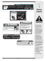
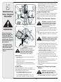
Safety • Assembly • Operation • Tips & Techniques • Maintenance • Troubleshooting • Parts Lists • Warranty
OPERATOR’S MANUAL
Model 24A-424G766 Shown
Chipper Shredder — Models 414 & 424
IMPORTANT
READ SAFETY RULES AND INSTRUCTIONS CAREFULLY BEFORE OPERATION
Warning: This unit is equipped with an internal combustion engine and should not be used on or near any unimproved forest-covered, brushcovered or grass-covered land unless the engine’s exhaust system is equipped with a spark arrester meeting applicable local or state laws (if any).
If a spark arrester is used, it should be maintained in effective working order by the operator. In the State of California the above is required by law
(Section 4442 of the California Public Resources Code). Other states may have similar laws. Federal laws apply on federal lands. A spark arrester
for the muffler is available through your nearest engine authorized service dealer or contact the service department, P.O. Box 361131 Cleveland,
Ohio 44136-0019.
PRINTED IN U.S.A.
TROY BILT LLC, P.O. BOX 361131 CLEVELAND, OHIO 44136-0019
FORM NO. 769-00830B
6/01/2005
This Operator’s Manual is an important part of your new chipper shredder. It will help you assemble, prepare and maintain the unit for best performance. Please read and understand what it says.
Table of Contents
Customer Support .............................................. 2
Safety Labels ...................................................... 3
Safe Operation Practices ................................... 4
Setting Up Your Chipper Shredder .................... 6
Operating Your Chipper Shredder ..................... 8
Maintaining Your Chipper Shredder ................ 10
Troubleshooting................................................ 12
Parts List ........................................................... 14
Warranty ............................................ Back Cover
Finding and Recording Model Number
BEFORE YOU START ASSEMBLING
YOUR NEW EQUIPMENT,
please locate the model plate on the equipment and copy
the information to the sample model plate provided to the
right. You can locate the model plate by standing behind the
unit and looking down at the frame below the engine. This
information will be necessary to use the manufacturer’s web
site and/or obtain assistance from the Customer Support
Department or an authorized service dealer.
www.troybilt.com
TROY-BILT LLC
P. O. BOX 3 6 1 1 3 1
CLEVELAND, OH 44136
330-558-7220
1-800-520-5520
Customer Support
Please do NOT return the unit to the retailer from which it was
purchased, without first contacting Customer Support.
If you have difficulty assembling this product or have any questions regarding the controls, operation, or maintenance of this
unit, you can seek help from the experts. Choose from the options below:
1. Visit mtdproducts.com. Click on the Service & Support menu option.
2. Phone a Customer Support Representative at 1 (800) 520-5520.
3. The engine manufacturer is responsible for all engine-related issues with regards to performance, power-rating, specifications, warranty and service. Please refer to the engine manufacturer’s Owner’s/Operator’s Manual, packed separately with
your unit, for more information.
2
������
��� ���� ������ ��������� ����� ����
����� ��������� ����� ���� ��� ���
��������� �������� ��������� ����� ����
�������������������������������������
������������������������
��������� ����� ����� �������
������� ��� �������� ���
����������� ��� �����������
�������������������������
����
���������������������������������������������������������������
�������������������������������������������������������������
�����������������������������������������������������������������
���������������������������������������������������������������
����������������������������������������������������������������������
���������������������������������������������������������������������
�������������������������������������������������������������������������
�������������������������������������������������������������������
���������
������
������������������������
�����������������������
�������������������������
�����������
������������������������������������������������������������������������
��������������������������������
������������������������������������������������������������������������
��������������������������������������������������������������������������
���������
������������������������������������������������������������������������
������������������������������������������������������������������
���������������������������������������������������������
�������������������������������������������������������������������������������
���������������������������������������������������������������������
���������������������
������������������������������������������������������������
�����������������������������������������������
��������������������������������������������������������
���������������������������������������������������������
�������������������������������������������������������
����������������������������������������������������������
���������������������������
�������� �� ��� ����� ������� ������ ���� ���
����������������������������������������������
1
Safety
Labels
���������� �� ������ ����� ��� ��� ���� �������� ����
��������������������������
����������������������������
�������������������
������������
������������������
������
������
���������������������������� ����������
� ������������������������������
� ��������������������
�������������������������������������
� �����������������������������
� ����������������������������� � � � � � �
� � � � � � � � � � � � � � � ������
������������������������
�����������������������
�������������������������
�����������
�������
���������������������������������
���������������������
��������������������������������������
����������������������������������
�������������������������������������
����������������������������������������
������������
�����������������������������������������
����������������������������������������
�������������������������������������������
������
����������������������������
���������������������������
����������������������������
3
WARNING
This symbol points
out important safety
instructions which, if
not followed, could
endanger the personal
safety and/or property
of yourself and others.
Read and follow all
instructions in this
manual before attempting to operate
this machine. Failure
to comply with these
instructions may result
in personal injury. When
you see this symbol.
HEED ITS WARNING!
Your Responsibility
Restrict the use
of this power machine
to persons who read,
understand
and follow the warnings
and instructions
in this manual
and on the machine.
2
Safe
Operation
Practices
WARNING
This symbol points
out important safety
instructions which, if
not followed, could
endanger the personal
safety and/or property
of yourself and others.
Read and follow all
instructions in this
manual before attempting to operate
this machine. Failure
to comply with these
instructions may result
in personal injury. When
you see this symbol.
WARNING: Engine Exhaust, some of its constituents, and certain vehicle components contain or emit chemicals known to State of California to cause cancer and
birth defects or other reproductive harm.
DANGER: This machine was built to be operated according to the rules for safe operation in this
manual. As with any type of power equipment, carelessness or error on the part of the operator can
result in serious injury. This machine is capable of amputating hands and feet and throwing objects.
Failure to observe the following safety instructions could result in serious injury or death.
Training
Preparation
1. Read, understand, and follow all instructions on the
machine and in the manual(s) before attempting to
assemble and operate. Keep this manual in a safe place for
future and regular reference and for ordering replacement
parts.
2. Be familiar with all controls and their proper operation.
Know how to stop the machine and disengage them quickly.
3. Never allow children under 16 years old to operate this
machine. Children 16 years old and over should read and
understand the operation instructions and safety rules in
this manual and should be trained and supervised by a
parent.
4. Never allow adults to operate this machine without proper
instruction.
5. Keep bystanders, helpers, pets, and children at least 75
feet from the machine while it is in operation. Stop machine
if anyone enters the area.
6. Never run an engine indoors or in a poorly ventilated area.
Engine exhaust contains carbon monoxide, an odorless
and deadly gas.
7. Do not put hands and feet near rotating parts or in the
feeding chambers and discharge opening. Contact with the
rotating impeller can amputate fingers, hands, and feet.
8. Never attempt to unclog either the feed intake or discharge
opening, remove or empty bag, or inspect and repair the
machine while the engine is running. Shut the engine off
and wait until all moving parts have come to a complete
stop. Disconnect the spark plug wire and ground it against
the engine.
1. Thoroughly inspect the area where the equipment is to
be used. Remove all rocks, bottles, cans, or other foreign
objects which could be picked up or thrown and cause
personal injury or damage to the machine.
2. Always wear safety glasses or safety goggles during operation or while performing an adjustment or repair, to protect
eyes. Thrown objects which ricochet can cause serious
injury to the eyes.
3. Wear sturdy, rough-soled work shoes and close-fitting
slacks and shirts. Loose fitting clothes or jewelry can be
caught in movable parts. Never operate this machine
in bare feet or sandals. Wear leather work gloves when
feeding material in the chipper chute.
4. Before starting, check all bolts and screws for proper tightness to be sure the machine is in safe working condition.
Also, visually inspect machine for any damage at frequent
intervals.
5. Maintain or replace safety and instructions labels, as
necessary.
6. To avoid personal injury or property damage use extreme
care in handling gasoline. Gasoline is extremely flammable
and the vapors are explosive. Serious personal injury can
occur when gasoline is spilled on yourself or your clothes
which can ignite. Wash your skin and change clothes
immediately.
a. Use only an approved gasoline container.
b. Extinguish all cigarettes, cigars, pipes, and other
sources of ignition.
c. Never fuel machine indoors.
d. Never remove gas cap or add fuel while the engine is hot
or running.
e. Allow engine to cool at least two minutes before refueling.
f. Never over fill fuel tank. Fill tank to no more than 1/2
inch below bottom of filler neck to provide space for fuel
expansion.
g. Replace gasoline cap and tighten securely.
h. If gasoline is spilled, wipe it off the engine and equipment. Move machine to another area. Wait 5 minutes
before starting the engine.
i. Never store the machine or fuel container inside where
there is an open flame, spark, or pilot light (e.g. furnace,
water heater, space heater, clothes dryer, etc.)
j. To reduce a fire hazard, keep machine free of grass,
leaves, or other debris build-up. Clean up oil or fuel
spillage and remove any fuel soaked debris.
k. Allow machine to cool at least 5 minutes before storing.
HEED ITS WARNING!
Your Responsibility
Restrict the use
of this power machine
to persons who read,
understand
and follow the warnings
and instructions
in this manual
and on the machine.
4
Operation
Maintenance & Storage
1. Do not put hands and feet near rotating parts or in the
feeding chambers and discharge opening. Contact with the
rotating impeller can amputate fingers, hands, and feet.
2. Before starting the machine, make sure the chipper chute,
feed intake, and cutting chamber are empty and free of all
debris.
3. Thoroughly inspect all material to be shredded and remove
any metal, rocks, bottles, cans, or other foreign objects
which could cause personal injury or damage to the
machine.
I4. f it becomes necessary to push material through the
shredder hopper, use a small diameter stick. Do not use
your hands or feet.
I5. f the impeller strikes a foreign object or if your machine
should start making an unusual noise or vibration,
immediately shut the engine off. Allow the impeller to come
to a complete stop. Disconnect the spark plug wire, ground
it against the engine and perform the following steps:
a. Inspect for damage.
b. Repair or replace any damaged parts.
c. Check for any loose parts and tighten to assure
continued safe operation.
6. Do not allow an accumulation of processed material to build
up in the discharge area. This can prevent proper discharge
and result in kickback of material through the feed opening.
7. Do not attempt to shred or chip material larger than
specified on the machine or in this manual. Personal injury
or machine damage could result.
8. Never attempt to unclog either the feed intake or discharge
opening while the engine is running. Shut the engine off,
wait until all moving parts have stopped, disconnect the
spark plug wire and ground it against the engine before
clearing debris.
9. Never operate without the shredder hopper, chipper chute,
or chute deflector properly attached to the machine. Never
empty or change discharge bag while the engine is running.
10. Keep all guards, deflectors and safety devices in place and
operating properly.
11. Keep your face and body back and to the side of the chipper
chute while feeding material into the machine to avoid
accidental kickback injuries.
12. Never operate this machine without good visibility or light.
13. Do not operate this machine on a paved, gravel or non-level
surface.
14. Do not operate this machine while under the influence of
alcohol or drugs.
15. Muffler and engine become hot and can cause a burn. Do
not touch.
16. Never pick up or carry machine while the engine is running.
1. Never tamper with safety devices. Check their proper
operation regularly.
2. Check bolts and screws for proper tightness at frequent
intervals to keep the machine in safe working condition.
Also, visually inspect machine for any damage and repair, if
needed.
3. Before cleaning, repairing, or inspecting, stop the engine
and make certain the impeller and all moving parts have
stopped. Disconnect the spark plug wire and ground it
against the engine to prevent unintended starting.
4. Do not change the engine governor settings or overspeed
the engine. The governor controls the maximum safe
operating speed of the engine.
5. Maintain or replace safety and instruction labels, as necessary.
6. Follow this manual for safe loading, unloading, transporting,
and storage of this machine.
7. Never store the machine or fuel container inside where
there is an open flame, spark or pilot light such as a water
heater, furnace, clothes dryer, etc.
8. Always refer to the operator’s manual for proper instructions
on off-season storage.
9. If the fuel tank has to be drained, do this outdoors.
10. Observe proper disposal laws and regulations for gas, oil,
etc. to protect the environment.
Do not modify engine
To avoid serious injury or death, do not modify engine in any
way. Tampering with the governor setting can lead to a runaway
engine and cause it to operate at unsafe speeds. Never tamper
with factory setting of engine governor.
Notice regarding Emissions
Engines which are certified to comply with California and federal
EPA emission regulations for SORE (Small Off Road Equipment)
are certified to operate on regular unleaded gasoline, and may
include the following emission control systems: Engine Modification (EM) and Three Way Catalyst (TWC) if so equipped.
Your Responsibility
Restrict the use of this power machine to persons who read, understand and follow the warnings and instructions in this manual
and on the machine.
2
Safe
Operation
Practices
WARNING
This symbol points
out important safety
instructions, which if
not followed, could
endanger the personal
safety and/or property
of yourself and others.
Read and follow all
instructions in this manual before attempting to
operate this machine.
Failure to comply with
these instructions may
result in personal injury.
When you see this
symbol.
HEED IT’S WARNING!
Your Responsibility
Restrict the use
of this power machine
to persons who read,
understand
and follow the warnings
and instructions
in this manual
and on the machine.
5
3
IMPORTANT: This unit is shipped without gasoline or oil
in the engine. Be certain to service engine with gasoline
and oil as instructed in the separate engine manual
before operating your machine.
�
Loose Parts In Carton
a. Debris Collection Bag
Setting Up
Your Chipper
Shredder
b. Tow Bar
c. Safety Glasses
�
d. Engine Oil
Lowering The Chipper Chute
(Model 24A-424G766 Only)
1. For shipping reasons, the unit is crated with its chipper
chute in a raised position. To pivot it downward,
proceed as follows:
a. Pull the spring latch upward.
b. Gently pivot the chipper chute down until it clicks
into the lock rod. See Figure 1.
WARNING
Figure 1
Never operate the
chipper shredder with
the chipper chute in the
raised position. Doing
so may result in property damage or serious
injury to the operator
or bystanders.
WARNING: Never operate the chipper
shredder with the chipper chute in the
raised position. Doing so may result in
property damage or serious injury to
the operator or bystanders.
Attaching The Debris
Collection Bag
2. To attach the bag:
a. Place the opening of the bag completely over the
chute deflector.
b. Position the bag so that the wing knobs which
secure the chute deflector to the impeller housing
are completely covered.
IMPORTANT
This unit is shipped
without gasoline or
oil in the engine. Be
certain to service
engine with gasoline
and oil as instructed
in the separate engine
manual before operating your machine.
NOTE: All references in
this manual to the left
or right side of the chipper shredder is from
the operating position
only. Exceptions, if any,
will be specified.
c. Pull on the drawstrap until the bag is tight around
chute deflector opening. See Figure 2.
Figure 2
Attaching The Tow Bar
3. To attach the tow bar:
a. Remove the spring pin and clevis pin from the end
of the tongue. See Figure 3.
b. Insert the tongue into the base.
c. Reinsert the clevis pin through aligning holes in
both the tongue and the base. Fasten with the
spring pin to secure. See Figure 3.
�
�
�
Figure 3
6
Know Your Chipper Shredder
������
������
������������
3
Setting Up
Your Chipper
Shredder
�������������
�����
���������
��������������
�������
��������
Model 24A-424G766 Shown
WARNING
Never operate the
chipper shredder with
the chipper chute in the
raised position. Use the
spring latch to lower
the chipper chute into
the operating position
before starting the
engine.
Figure 4
WARNING: Never operate the chipper
shredder with the chipper chute in the
raised position. Use the spring latch
to lower the chipper chute into the
operating position before starting the
engine.
Now that you have set up your chipper shredder for
operation, get aquainted with its controls and features. These are described below and illustrated on
this page. This knowledge will allow you to use your
new equipment to its fullest potential.
Chipper Chute
Branches up to 3” in diameter may be fed into the
chipper chute for chipping. See Figure 4.
Hopper
Leaves, twigs and branches up to 1/2-inch in diameter may be placed into the hopper for shredding.
See Figure 4.
IMPORTANT: Never place branches with a diameter
greater than 1/2-inch in the hopper. Doing so can result
in serious damage to your unit’s shredder blade, flails or
impeller.
Spring Latch
The spring latch is located on the top of the hopper.
It is used to release or lock the chipper chute in a
raised position for storage or for transporting. See
Figure 4.
Lock Rod
The lock rod is located on the chipper chute support. It is used to release or lock the chipper chute
in a lowered position for operation. See Figure 4.
Tow Bar
Use the tow bar to tow the chipper shredder behind
a tractor to a job site. See Figure 4.
Handle
Use the handle when manually transporting the
chipper shredder. See Figure 4.
Starter Handle
The starter handle is located on the engine. Pull the
starter handle to start engine. See Figure 4.
Engine Controls
See the Briggs & Stratton Owner/Operator manual
packed with your unit for the location and function
of the controls on the engine.
7
IMPORTANT
Never place branches
with a diameter greater
than 1/2-inch in the
hopper. Doing so
can result in serious
damage to your unit’s
shredder blade, flails or
impeller.
4
Operating
Your Chipper
Shredder
WARNING: The operation of any
chipper shredder can result in
foreign objects being thrown into the
eyes, which can damage your eyes
severely. Always wear the safety
glasses provided with this unit or eye
shields before chipping or shredding
and while performing any adjustments
or repairs.
Gas and Oil Fill-Up
Service the engine with gasoline and oil as instructed in
the separate engine manual packed with your chipper
shredder. Read instructions carefully.
WARNING
The operation of any
chipper shredder
can result in foreign
objects being thrown.
Always wear the safety
glasses provided with
this unit or eye shields
before chipping or
shredding and while
performing any adjustments or repairs.
Never fill fuel tank
indoors with engine
running or until the
engine has been
allowed to cool for
at least two minutes
after running.
Never run the engine
indoors or in a poorly
ventilated area. Engine exhaust contains
carbon monoxide, an
odorless and deadly
gas.
Never stop the engine
by moving the choke
lever into the CHOKE
position. Backfire,
fire or engine damage
could result.
����
WARNING: Never fill fuel tank indoors
with engine running or until the engine
has been allowed to cool for at least
two minutes after running.
Starting Engine
Figure 5
1. Attach spark plug wire to spark plug. Make certain
the metal cap on the end of the spark plug is
fastened securely over metal tip on the spark plug.
2. Open fuel shut-off valve ( Model
424).
����
3. Move choke control lever to
CHOKE position. See Figure 5.
NOTE: A warm engine may not require choking.
4. Move throttle control lever to FAST (rabbit) position
(Model 414) or push rocker switch to ON (Model
424). See Figure 5.
5. Grasp starter handle and pull rope out slowly until
engine reaches start of compression cycle (rope will
pull slightly harder at this point).
NOTE: A “clanking” noise may be heard when pulling
the starter rope. It is completely normal and does NOT
indicate a malfunction of any kind.
Figure 6
6. Pull rope with a rapid, continuous, full arm stroke.
Keep a firm grip on starter handle. Let rope rewind
slowly.
Stopping Engine
1. Move throttle control lever to STOP position (Model
414) or push rocker switch to OFF (Model 424). See
Figure 6.
7. Repeat the previous steps until engine starts. When
engine starts, move choke control gradually to RUN
position until the engine is running smoothly.
NOTE: See your engine manual packed with your unit for
more detailed instructions.
WARNING: Never run the engine
indoors or in a poorly ventilated area.
Engine exhaust contains carbon
monoxide, an odorless and deadly
gas.
CAUTION: Never stop the engine by
moving the choke lever into the CHOKE
position. Backfire, fire or engine damage
could result.
8
4
Operating The Chipper Shredder
Shredding
Yard waste such as leaves and pine needles can be
placed in the hopper for shredding. After material has
been processed by the shredder blade and flails, it will be
forced out of the chute deflector, and, if attached, into a
debris collection bag.
Observe the following guidelines when shredding yard
debris:
1. Never attempt to shred material other than normal
yard debris (leaves, twigs, pine cones, etc.).
Operating
Your Chipper
Shredder
2. Avoid shredding fibrous plants such as tomato vines
until they are thoroughly dried out. Fresh vines do not
shred well and tend to wrap themselves around the
impeller and flails.
3. Place reasonable amounts of debris into the hopper at
a time. Do not overload the hopper.
4. Allow the material in the hopper to be drawn into
the blades and shredded before adding additional
debris to the hopper. Failure to due so may result in a
clogged hopper, clogged chute deflector or a stalled
engine.
5. Avoid placing twigs longer than 24 inches into the
hopper. Twigs longer than 24 inches may result in a
clogged hopper.
6. Never place branches with a diameter greater than
1/2-inch in the hopper. Doing so can result in serious
damage to the unit’s shredder blade, flails or impeller.
Clearing the Hopper
Should the hopper become clogged with debris during
operation, proceed as follows:
1. Grasp the handle with both hands and gently agitate
the chipper shredder to help loosen debris, drawing it
into the impeller.
If the clog does not clear, proceed as follows:
1. Stop engine.
Figure 7
Chipping
WARNING
WARNING: Never operate the chipper shredder without chipper chute
lowered into the operating position.
Branches up to 3” in diameter can be fed into the
chipper chute. Observe the following guidelines when
chipping branches:
1. Keep both hands firmly on the branch as you feed it
into the chipper chute.
2. Never feed more than one branch into the chipper
chute at a time.
3. Never feed anything other than branches (or wood)
into the chipper chute.
4. Apply intermittent pressure (force, in short pulses)
while feeding larger (2- 3-inch diameter) branches
into the chipper chute, to avoid bogging or stalling
the engine.
2. Use your hands to remove any debris found near the
top of the hopper.
IMPORTANT: Never feed branches with a diameter
greater than three (3) inches into the chipper chute.
3. Use a branch (or other available device, i.e. broomDoing so can result in serious damage to your unit’s
stick) to dislodge debris located toward the base of the chipper blades, flails or impeller.
hopper.
NOTE: For best performance, always operate the
4. Restart engine.
unit with sharp chipper blades. If a noticeable loss in
performance is encountered while chipping branches,
NOTE: If you’re unable to pull the starter rope as a
the chipper blades should be replaced.
result of accumulated debris near the impeller, follow
instructions under the heading Cleaning the Reduction
Chamber in the “Maintaining Your Chipper Shredder”
section of this manual.
Emptying the Debris Collection Bag
1. Stop engine.
2. Squeeze the locking buckle release the bag’s
drawstrap before loosening it from the chute deflector. See Figure 7.
3. Empty the bag and reattach to the chute deflector
opening. Refer to Figure 2.
9
Never operate the chipper shredder without
chipper chute lowered
into the operating
position.
IMPORTANT
Never place branches
with a diameter greater
than 1/2-inch in the hopper. Doing so can result
in serious damage to your
unit’s shredder blade,
flails or impeller.
IMPORTANT
Never feed branches with
a diameter greater than
three (3) inches into the
chipper chute. Doing so
can result in serious damage to your unit’s chipper
blades, flails or impeller.
5
Maintaining
Your Chipper
Shredder
under extremely dusty conditions. Replace the air
cleaner cartridge once a season. To service the air
cleaner, refer to the separate engine manual.
�
3. The spark plug should be cleaned and the gap reset
once a season. Refer to the separate engine manual
for correct plug type and gap specifications.
Chipper Shredder Care
�
�
Before each use, visually inspect your chipper shredder
for loose (or missing) nuts and bolts. Securely tighten
(or replace) all hardware before operating the chipper
shredder.
Cleaning The Reduction Chamber
Figure 8
WARNING
Always stop engine,
disconnect spark plug,
and ground against
engine before cleaning,
lubricating or doing any
kind of maintenance on
your machine.
The impeller’s chipper blades are sharp.
Wear leather work
gloves to protect your
hands.
�
WARNING: The impeller’s shredder
blade and chipper blades are sharp.
Wear leather work gloves to protect
your hands when cleaning out the
reduction chamber.
If the reduction chamber becomes clogged with debris,
the shredder screen can be pivoted upward so that you
can clean the surrounding area. To do so, proceed as
follows:
1. Stop engine, disconnect spark plug, and make certain
the chipper shredder has come to a complete stop.
WARNING: The muffler and surrounding
area will be hot if the engine has been
running. Use caution and protect your
hands if working near the muffler.
�
�
Model 24A-424G766 Shown
Figure 9
WARNING: Always stop engine,
disconnect spark plug, and ground
against engine before cleaning,
lubricating or doing any kind of
maintenance on your machine.
Lubrication
1. Lubricate the chipper chute hinge a with light oil
once a season.
2. Lubricate the pivot points on the chute deflector with
light oil once a season.
3. Refer to the Briggs & Stratton Owner/Operator
manual packed with your unit for engine lubrication
instructions.
Engine Care
Refer to the Maintenance section of the Briggs &
Stratton Owner/Operator manual packed with your unit.
Read and follow instructions carefully.
1. Check engine oil level before each use as
instructed in the separate engine manual.
2. Clean air cleaner’s precleaner every 25 hours
under normal conditions. Clean every few hours
2. a. If attached, remove debris bag. Remove the two
wing knobs on either side of the chute deflector and
pivot the chute deflector upward. See Figure 8.
b. Remove the hairpin clip from the clevis pin which
extends through the housing and shredder screen.
See Figure 8. Remove clevis pin.
c. Pivot the shredder screen upward and clean the
surrounding area by scraping away debris.
3. Confirm that the spark plug wire is disconnected
and away from spark plug. Pull on the starter rope
two-to-three times to purge any remaining debris from
the reduction chamber
4. When the area is cleaned, pivot the shredder screen
downward and re-secure with the clevis pin and
hairpin clip removed earlier.
5. Reattach the debris collection bag to the chute deflector, if desired.
Sharpening Or Replacing Chipper
Blades
WARNING: The impeller’s chipper
blades are sharp. Wear leather work
gloves to protect your hands.
1. Stop engine, disconnect spark plug, and make certain
the chipper shredder has come to a complete stop.
10
5
2. Pivot the shredder screen upward as instructed under
the heading Cleaning the Reduction Chamber.
3. a. Remove the chipper chute support brace from the
frame by removing the two hex bolts and saddle
washers which secure it. See Figure 9.
b. Remove the chipper chute by removing three hex
nuts and washers which secure it to the impeller
housing. See Figure 9.
• Rotate the impeller by hand until one of the two
chipper blades is visible through the impeller
housing opening.
c. Remove the blade by removing the internal hex
screws, lock washers and hex nuts which secure it
to the impeller. Retain the hardware.
Maintaining
Your Chipper
Shredder
Figure 10
NOTE: Use a 3/16” hex key (Allen) wrench on the outside
of the blade and a 1/2” box (or socket) wrench on the
inside of the impeller. Hold the Allen wrench stationary
and rotate the box (or socket) wrench to loosen the nut.
4. Install a replacement blade (Part No. 742-0544) with
the hardware removed earlier or sharpen.
WARNING
IMPORTANT: When sharpening the blade, protect hands
by using gloves. Follow the original angle of grind and
make sure to remove an equal amount from each blade.
5. To replace the other blade, rotate the impeller to
expose the second blade and repeat the steps above.
�
�
�
NOTE: Make certain blades are reassembled with the
sharp edge outward (toward the chipper chute). Torque
hardware to between 20 ft.-lbs and 25 ft.-lbs.
The shredder blade is
sharp. Wear leather
work gloves to
protect your hands.
Figure 11
NOTE: Use a 3/16” hex key (Allen) wrench on the
outside of the shredder blade and a 1/2” box (or socket)
wrench on the inside of the shredder blade. Hold the
Allen wrench stationary and rotate the box (or socket)
WARNING: The shredder blade is sharp. wrench to loosen the nut.
Wear leather work gloves to protect
c. Remove the hex bolt, lock washer, and flat washer
your hands.
to completely free shredder blade. See Figure 11.
Sharpening Or Replacing The
Shredder Blade
1. Stop engine,disconnect spark plug, and make certain
that all moving parts have come to a complete stop.
2. Remove the two flange nuts (and hex bolts) which
secure the hopper support bracket to the impeller
housing. Retain the hardware. See Figure 10.
3. Pivot the shredder screen upward as instructed under
the heading Cleaning the Reduction Chamber.
4. a. Remove six flange nuts which secure hopper inlet
guide to impeller housing. See Figure 11.
• Carefully separate the hopper assembly from the
impeller housing and set it aside.
• Insert a piece of wood into the chute deflector
opening to stabilize the impeller and prevent it from
rotating when removing the shredder blade.
b. Remove the two internal hex screws, hex lock nuts,
and lock washers which secure the shredder blade
to the impeller. See Figure 11.
IMPORTANT: If sharpening the blade for reuse, follow
the original angle of grind as a guide. Make certain each
cutting edge receives an equal amount of grinding to
prevent an unbalanced blade. Remove metal from the
heavy side until it is balanced evenly.
IMPORTANT: When reassembling the blade, tighten
center bolt to between 45 ft.-lbs and 60 ft.-lbs and the
two out bolts to between 20 ft.-lbs and 25 ft.-lbs.
Storing Your Chipper Shredder
1. Clean the equipment thoroughly.
2. Wipe equipment with an oiled rag to prevent rust.
3. Refer to engine manual for correct engine storage
instructions
4. Store unit in a clean, dry area. Do not store next to
corrosive materials such as fertilizer.
11
IMPORTANT
Make certain chipper
blades are reassembled with the sharp
edge outward (toward
the chipper chute).
Torque hardware to
between 20 ft.-lbs and
25 ft.-lbs.
IMPORTANT
When reassembling the
shredder blade, tighten
center bolt to between
45 ft.-lbs and 60 ft.-lbs
and the two out bolts to
between 20 ft.-lbs and
25 ft.-lbs.
6
Problem
Engine fails to start
Trouble
Shooting
Engine runs erratic
For repairs beyond
the minor adjustments
listed here, contact
an authorized service
dealer.
Engine overheats
Occasional skips
(hesitates) at
high speed
Excessive
Vibration
Unit does not
discharge
Rate of discharge
slows considerably
or composition of
discharged material
changes
Cause
Remedy
1. Throttle lever not in correct starting
position (if equipped).
1. Move throttle lever to FAST or
START position.
2. Spark plug wire disconnected.
2. Connect wire to spark plug.
3. Choke not in CHOKE position (if
equipped).
3. Move choke lever to CHOKE
position.
4. Fuel tank empty or stale fuel.
4. Fill tank with clean, fresh gasoline.
5. Engine not primed (if equipped).
5. Prime engine as instructed in
Engine Manual.
6. Faulty spark plug.
6. Clean, adjust gap, or replace.
7. Blocked fuel line.
7. Clean fuel line.
8. Engine flooded.
8. Wait a few minutes to restart, but
do not prime.
1. Spark plug wire loose.
1. Connect and tighten spark
plug wire.
2. Unit running on CHOKE (if equipped).
2. Move choke lever to OFF position.
3. Blocked fuel line or stale fuel.
3. Clean fuel line; fill tank with clean,
fresh gasoline.
4. Vent in gas cap plugged.
4. Clear vent.
5. Water or dirt in fuel system.
5. Drain fuel tank. Refill with
fresh fuel.
6. Dirty air cleaner.
6. Refer to engine manual.
7. Carburetor out of adjustment.
7. See authorized service dealer.
1. Engine oil level low.
1. Fill crankcase with proper oil.
2. Dirty air cleaner.
2. Refer to engine manual.
3. Carburetor not adjusted properly.
3. See authorized service dealer.
1. Spark plug gap too close.
1. Adjust gap to .030”.
2. Carburetor idle mixture adjustment
improperly set.
2. See authorized service dealer.
1. Loose parts or damaged impeller.
1. See authorized service dealer.
1. Chute deflector clogged.
1. Stop engine immediately and
disconnect spark plug wire. Clean
flail screen and inside of discharge
opening.
2. Foreign object lodged in impeller.
2. Stop engine and disconnect spark
plug wire. Remove lodged object.
3. Low engine RPM.
3. Always run engine at full throttle.
1. Low engine RPM.
1. Always run engine at full throttle.
2. Chipper blade dull.
2. Replace chipper blade or see your
authorized service dealer.
12
7
Models 414 & 424
�
1
681-04009
Impeller Assembly Complete
2
710-1054
Machine Screw, 5/16-24 x 1.0
3
711-0833B
Clevis Pin,.496
4
712-0411
Hex Lock Nut, 5/16-24
5
715-0166
Spiral Pin,.156 x 1.0
6
719-0329
Flail
7
736-0119
Lock Washer, 5/16
8
742-04050
Shredder Blade
9
742-0544
Chipper Blade
10
781-0735
Retainer Clip
�
�
�
�
��
�
�
�
�
�
To order replacement
parts, contact
1-800-520-5520,
1-330-558-7220
or visit
www.troybilt.com.
�
�
�
�
�
�
�
1
681-0133
Tongue Hitch Mount
2
681-0134A
Base Hitch Mount
3
710-3001
Hex Cap Screw, 3/8-16 x.88
4
711-0299
Clevis Pin,.625 x 2.4
5
711-0835
Clevis Pin,.50 x 4.62
6
712-3017
Hex Nut, 3/8-16
7
732-0194
Spring Pin
8
736-0133
Flat Washer,.411 x 1.25 x 1.0
9
736-0169
Lock Washer, 3/8
�
�
13
Parts List
�
Models 414 & 424
���
���
���
��
���
���
�
���
��
���
��
�
���
�
��
��
��
��
�
�
�
��
���
�
��
��
��
���
��
���
���
���
���
�
��
��
��
��
��
��
�
���
��
���
��
��
��
��
�� ��
�
��
��
���
��
��
��
��
��
��
��
��
�
��
��
��
��
��
��
��
��
��
��
��
��
��
��
��
��
��
��
��
��
��
��
��
��
† Model 424 Only
‡ Model 414 Only
14
1
681-04006† Upper Chipper Chute Assembly
34 681-04002
Outer Flail Housing Assembly
2
681-04007† Lower Chipper Chute Assembly
35 710-0157
Hex Cap Screw, 5/16-24 x.75
3
710-0106†
Hex Cap Screw, 1/4-20 x 1.25
36 710-0502A
Hex Sems Screw, 3/8-16 x 1.25
4
710-3013
Hex Cap Screw, 1/4-20 x.5
37 710-0825
Hex Cap Screw, 1/4-20 x 3.75
5
712-3010
Hex Nut, 5/16-18
38 710-3025
Hex Cap Screw, 5/16-18 x.625
6
712-3027
Hex Lock Nut 1/4-20
39 726-0211
U-Nut, 5/16-18
7
714-0104†
Cotter Pin
40 736-0119
Lock Washer, 5/16
8
728-0175†
Pop Rivet
41 736-0170
Special Lock Washer, 5/16
9
732-0306A† Compression Spring,.531 x 1.75
42 750-0793
Hinge Spacer,.265 x.380 x 1.66
43 681-0048
Knob Assembly (Incl. ref.# 12 & 61)
10 735-0249A† Chute Flap
11 736-0140†
Flat Washer
12 736-0242
Bell Washer.340 ID x.872 OD
720-0170
44 681-0094
Chute Deflector Assembly
13 736-0451
Washer,.320 ID x.93 OD
45 711-0835
Clevis Pin,.50 x 4.62
Lock Rod
46 714-0149B
Internal Cotter Pin
15 749-1004†
Chipper Chute Support
47 719-04070
Shredder Screen
16 781-04032† Chipper Chute Hinge
48 726-0214
Push Cap, 5/8
17 781-0633†
Chute Flap Strip
49 734-1845
Wheel, 10 x 4 x 4
18 681-04011
Shredder Hopper Assembly
50 736-0366
Flat Washer,.625 x 1.0
19 710-0809
Hex Cap Screw, 1/4-20 x 1.250
51 738-0813
Axle, 22.47”
20 710-0805
Hex Cap Screw, 5/16-18 x 1.50
52 737-0195‡
Elbow Fitting
21 712-04065† Flange Lock Nut, 3/8-16
53 737-0132†
Oil Drain End Cap
22 712-3004A
54 737-0298†
Oil Drain Pipe
23 732-04167† Torsion Spring
55 710-1254
Hex Cap Screw, 3/8-24 x 2.2
24 736-0182†
Spring Washer,.50 x 1.0 x.022
56 736-0217
Lock Washer, 3/8
25 736-0326†
Flat Washer,.50 x 1.0 x.0125
57 736-0247
Flat Washer,.406 x 1.25
26 738-0430†
Shoulder Screw, 3/8-16,.50 x.685
58 681-04009
Impeller Assembly
27 749-04103
Hopper Handle
28 749-04104
Tube Support
(See page 13 for Impeller Parts)
59 736-0173
Flat Washer,.28 x.74 x.063
29 781-04007
Shredder Plate
60 726-0233†
Push Nut,.25ID x.50OD
30 781-04027
Hopper Support Bracket
61 726-0201
Speed Nut,.3125ID
31 781-04033
Inlet Guide
62 681-0095‡
Chipper Chute
32 681-0117
Inner Flail Housing Assembly
— 664-04023
Debris Collection Bag (Not Shown)
— 723-0400
Safety Glasses
33 681-0183A† Frame Assembly
681-0184A‡ Frame Assembly
† Model 424 Only
‡ Model 414 Only
15
Parts List
Knob Only, 5/16-18
14 747-04163†
Flange Lock Nut, 5/16-18
7
To order replacement
parts, contact
1-800-520-5520,
1-330-558-7220
or visit
www.troybilt.com.
MANUFACTURER’S LIMITED WARRANTY FOR
The limited warranty set forth below is given by Troy-Bilt LLC with respect
to new merchandise purchased and used in the United States and/or its
territories and possessions, and by MTD Products Limited with respect to
new merchandise purchased and used in Canada and/or its territories and
possessions (either entity respectively, “Troy-Bilt”).
“Troy-Bilt” warrants this product (excluding its normal wear parts as
described below) against defects in material and workmanship for a period
of two (2) years commencing on the date of original purchase and will, at
its option, repair or replace, free of charge, any part found to be defective
in materials or workmanship. This limited warranty shall only apply if
this product has been operated and maintained in accordance with the
Operator’s Manual furnished with the product, and has not been subject to
misuse, abuse, commercial use, neglect, accident, improper maintenance,
alteration, vandalism, theft, fire, water, or damage because of other peril
or natural disaster. Damage resulting from the installation or use of any
part, accessory or attachment not approved by Troy-Bilt for use with
the product(s) covered by this manual will void your warranty as to any
resulting damage.
Normal wear parts are warranted to be free from defects in material and
workmanship for a period of thirty (30) days from the date of purchase.
Normal wear parts include, but are not limited to items such as: batteries,
belts, blades, blade adapters, grass bags, rider deck wheels, seats, snow
thrower skid shoes, friction wheels, shave plates, auger spiral rubber and
tires.
HOW TO OBTAIN SERVICE: Warranty service is available, WITH
PROOF OF PURCHASE, through your local authorized service dealer. To
locate the dealer in your area:
In the U.S.A.
Check your Yellow Pages, or contact Troy-Bilt LLC at P.O. Box 361131,
Cleveland, Ohio 44136-0019, or call 1-866-840-6483 or 1-330-558-7220,
or log on to our Web site at www.troybilt.com.
In Canada
Contact MTD Products Limited, Kitchener, ON N2G 4J1, or call 1-800-6681238 or log on to our Web site at www.mtdcanada.com.
This limited warranty does not provide coverage in the following cases:
a.
b.
c.
The engine or component parts thereof. These items may
carry a separate manufacturer’s warranty. Refer to applicable
manufacturer’s warranty for terms and conditions.
Log splitter pumps, valves, and cylinders have a separate
one- year warranty.
Routine maintenance items such as lubricants, filters, blade
sharpening, tune-ups, brake adjustments, clutch adjustments,
d.
e.
f.
g.
h.
deck adjustments, and normal deterioration of the exterior finish
due to use or exposure.
Service completed by someone other than an authorized service
dealer.
Troy-Bilt does not extend any warranty for products sold or
exported outside of the United States and/or Canada, and
their respective possessions and territories, except those sold
through Troy-Bilt’s authorized channels of export distribution.
Replacement parts that are not genuine Troy-Bilt parts.
Transportation charges and service calls.
If Products are used commercially. (Troy-Bilt may separately
offer Limited Commercial Warranties on certain select products.
Ask your dealer or retailer for details or contact Troy-Bilt Service
for more information).
No implied warranty, including any implied warranty of merchantability of fitness for a particular purpose, applies after the applicable
period of express written warranty above as to the parts as identified. No other express warranty, whether written or oral, except as
mentioned above, given by any person or entity, including a dealer or
retailer, with respect to any product, shall bind Troy-Bilt. During the
period of the warranty, the exclusive remedy is repair or replacement
of the product as set forth above.
The provisions as set forth in this warranty provide the sole and
exclusive remedy arising from the sale. Troy-Bilt shall not be liable
for incidental or consequential loss or damage including, without
limitation, expenses incurred for substitute or replacement lawn care
services or for rental expenses to temporarily replace a warranted
product.
Some states do not allow the exclusion or limitation of incidental or
consequential damages, or limitations on how long an implied warranty
lasts, so the above exclusions or limitations may not apply to you.
In no event shall recovery of any kind be greater than the amount of the
purchase price of the product sold. Alteration of safety features of the
product shall void this warranty. You assume the risk and liability for
loss, damage, or injury to you and your property and/or to others and their
property arising out of the misuse or inability to use the product.
This limited warranty shall not extend to anyone other than the original
purchaser or to the person for whom it was purchased as a gift.
HOW STATE LAW RELATES TO THIS WARRANTY: This limited warranty gives you specific legal rights, and you may also have other rights
which vary from state to state.
IMPORTANT: Owner must present Original Proof of Purchase to obtain
warranty coverage.
Troy-Bilt LLC, P.O. BOX 361131 CLEVELAND, OHIO 44136-0019; Phone: 1-866-840-6483, 1-330-558-7220
MTD Canada Limited - KITCHENER, ON N2G 4J1; Phone 1-800-668-1238