1
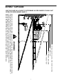
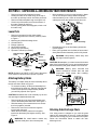
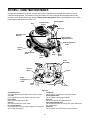
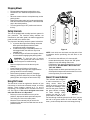
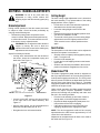
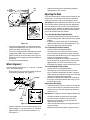
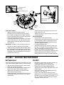
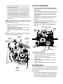
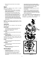
Operator’s Manual
Riding Mower
Internal Bagging System
Model
13A-344-563
LR927
IMPORTANT:
Read safety rules and
instructions carefully
before operating equipment.
60 OTTAWA STREET, KITCHENER, ONTARIO N2G 3S7
PRINTED IN CANADA
OGRM-4004
TABLE OF CONTENTS
Content
Page
Warranty........................................................................................................... 2
Important Safe Operation Practices .................................................................. 4
Slope Gauge..................................................................................................... 7
Assembling Your Riding Mower ........................................................................ 8
Know Your Riding Mower.................................................................................. 10
Operating Your Riding Mower........................................................................... 12
Making Adjustments ......................................................................................... 14
Servicing Your Rider Mower ............................................................................. 16
Maintaining Your Riding Mower ........................................................................ 18
Off-Season Storage .......................................................................................... 20
Troubleshooting ................................................................................................ 20
Parts List........................................................................................................... 22
FINDING MODEL NUMBER
This Operator’s Manual is an important part of your new riding mower. It will help you assemble, prepare
and maintain the unit for best performance. Please read and understand what it says.
Before you start assembling your new equipment, please locate the model plate on the
equipment and copy the information from it in the space provided below. The information on
the model plate is very important if you need help from our Customer Support Department or
an authorized dealer.
•
You can locate the model plate by pivoting the cover upward and looking under the frame. A sample
model plate is explained below. For future reference, please copy the model number and the serial
number of the equipment in the space below.
Model Number
Numéro de modèle
XXX-XXXXXX
Serial Number
Numéro de série
XXXXXXXXXXX
Copy the model number here:
Copy the serial number here:
TROYBILT - CANADA
KITCHENER, ON N2G 4J1
CALLING CUSTOMER SUPPORT
If you have difficulty assembling this product or have any questions regarding the controls, operation or
maintenance of this unit, please call your service dealer.
Before you call, make sure that you have your model and serial numbers ready. By having
the model and serial numbers ready, you help the Customer Support Representative give
you faster service.
2
THREE (3) YEAR LIMITED WARRANTY
For three (3) years from the date of original purchase of our products, we will either repair or replace, at its
option, free of charge, F.O.B. Factory or authorized service firm, any part found to be DEFECTIVE IN
MATERIAL and WORKMANSHIP for the original purchaser. all transportation charges on parts submitted
for replacement under this warranty must be paid by the purchaser unless return is requested by the
manufacturer.
This warranty DOES NOT apply to any part which has become inoperative through misuse, excessive use,
accident, neglect, improper maintenance or alterations by unauthorized persons.
The limited warranty does not extend to the replacement of parts which are not defective, but where regular
usage has exhausted the life of the part.
ENGINES, ELECTRIC START KITS, PEERLESS TRANSMISSIONS AND PEERLESS TRANSAXLES ARE
WARRANTED BY THEIR RESPECTIVE MANUFACTURER. ALL CLAIMS AGAINST THESE COMPONENTS
MUST BE HANDLED THROUGH THE RESPECTIVE MANUFACTURER’S SERVICE DEALERS.
Belts, light bulbs, clutch parts (friction wheels), grass bags, tires, seats, rider deck wheels and cutting
blades are covered by a 60 day limited warranty.
Batteries are covered by a 90 day limited warranty.
Fuses, shear bolts and blade adapters are considered consumable items and as such are not warranted.
NOTE: Regular maintenance replacement parts and related inspections and adjustments are excluded
from coverage when made as part of normal maintenance service.
TRACTOR ATTACHMENT WARRANTY
Mower decks included with your product, or sold separately, as an attachment for your garden tractors
will be warranted according to the above terms of the manufacturer three (3) year limited consumer
warranty.
ALL OTHER ATTACHMENTS will be sold under the same condition as above except the warranty will be
ONE YEAR FROM DATE OF ORIGINAL PURCHASE.
PERSONAL USE
THE FOREGOING PARAGRAPHS CONSTITUTE THE MANUFACTURER’S ENTIRE WARRANTY WITH
RESPECT TO ANY PRODUCT PURCHASED AND USED FOR PERSONAL FAMILY,
HOUSEHOLD/RESIDENTIAL PURPOSES, AS DISTINGUISHED FROM COMMERCIAL USAGE.
COMMERCIAL USE
ALL APPLICATIONS OTHER THAN PERSONAL USE AS OUTLINED ABOVE, ARE CONSIDERED
COMMERCIAL USAGE.
New products purchased for commercial usage are warranted in the same manner and to the same extend
EXCEPT the term of warranty will be 60 DAYS from date of purchase.
WARRANTY SERVICE CAN ONLY BE PERFORMED BY AN AUTHORIZED SERVICE DEALER. ANY
NON-ORIGINAL EQUIPMENT REPLACEMENT PART USED ON OR IN A PRODUCT UNDER WARRANTY
WILL BE EXCLUDED FROM THAT WARRANTY COVERAGE, AS WILL BE ANY RELATED DAMAGED
COMPONENTS RESULTING FROM THE INSTALLATION OF A REPLACEMENT PART FROM ANOTHER
SOURCE OTHER THAN THE MANUFACTURER.
3
SECTION 1: IMPORTANT SAFE OPERATION PRACTICES
This symbol points out important safety instructions which, if not followed, could endanger the
personal safety and/or property of yourself and others. Read and follow all instructions in this manual
before attempting to operate your rider mower. Failure to comply with these instructions may result in
personal injury. When you see this symbol—heed its warning.
Your rider mower was built to be operated according to the rules for safe operation in this manual. As with any type
of power equipment, carelessness or error on the part of the operator can result in serious injury. If you violate any
of these rules, you may cause serious injury to yourself or others.
General Operation
•
•
•
•
•
•
•
•
•
•
•
•
•
•
Read, understand, and follow all instructions in the
manual and on the machine before starting. Keep
this manual in a safe place for future and regular
reference and for ordering replacement parts.
Only allow responsible individuals familiar with the
instructions to operate the machine. Know controls
and how to stop the machine quickly.
Do not put hands or feet under cutting deck or near
rotating parts.
Clear the area of objects such as rocks, toys, wire,
etc., which could be picked up and thrown by the
blade. A small object may have been overlooked
and could be accidentally thrown by the mower in
any direction and cause injury to you or a
bystander. To help avoid a thrown objects injury,
keep children, bystanders and helpers at least 75
feet from the mower while it is in operation. Always
wear safety glasses or safety goggles during
operation or while performing an adjustment or
repair, to protect eyes from foreign objects. Stop
the blade(s) when crossing gravel drives, walks or
roads.
Be sure the area is clear of other people before
mowing. Stop machine if anyone enters the area.
Never carry passengers.
Disengage blade(s) before shifting into reverse and
backing up. Always look down and behind before
and while backing.
Be aware of the mower and attachment discharge
direction and do not point it at anyone. Do not
operate the mower without either the entire grass
catcher or the chute guard in place.
Slow down before turning. Operate the machine
smoothly. Avoid erratic operation and excessive
speed.
Never leave a running machine unattended.
Always turn off blade(s), place transmission in
neutral, set park brake, stop engine and remove
key before dismounting.
Turn off blade(s) when not mowing.
Stop engine and wait until blade(s) comes to a
complete stop before (a) removing grass catcher or
unclogging chute, or (b) making any repairs,
adjusting or removing any grass or debris.
Mow only in daylight or good artificial light.
•
•
•
•
•
•
Do not operate the machine while under the
influence of alcohol or drugs.Watch for traffic when
operating near or crossing roadways.
Use extra care when loading or unloading the
machine into a trailer or truck. This unit should not
be driven up or down a ramp onto a trailer or truck
under power, because the unit could tip over,
causing serious personal injury. The unit must be
pushed manually on a ramp to load or unload
properly.
Never make cutting height adjustment while engine
is running, if operator must dismount to do so.
Wear sturdy, rough-soled work shoes and closefitting slacks and shirts. Do not wear loose fitting
clothes or jewelry. They can be caught in moving
parts. Never operate a unit in bare feet, sandals, or
sneakers.
Check overhead clearance carefully before driving
under power lines, wires, bridges or low hanging
tree branches, before entering or leaving buildings,
or in any other situation where the operator may be
struck or pulled from the unit, which could result in
serious injury.
Disengage all attachment clutches, thoroughly
depress the brake pedal, and shift into neutral
before attempting to start engine.
Your mower is designed to cut normal residential
grass of a height no more than 10". Do not attempt
to mow through unusually tall, dry grass (e.g.,
pasture) or piles of dry leaves. Debris may build up
on the mower deck or contact the engine exhaust
presenting a potential fire hazard.
Slope Operation
•
•
4
Slopes are a major factor related to loss of control
and tip-over accidents which can result in severe
injury or death. All slopes require extra caution. If
you cannot back up the slope or if you feel uneasy
on it, do not mow it.
For your safety, use the slope gauge included as
part of this manual to measure slopes before
operating this unit on a sloped or hilly area. If the
slope is greater than 15° as shown on the slope
gauge, do not operate this unit in that area or
serious injury could result.
Do:
•
•
•
•
•
•
•
•
•
Mow up and down slopes, not across.
Remove obstacles such as rocks, limbs, etc.
Watch for holes, ruts or bumps. Uneven terrain
could overturn the machine. Tall grass can hide
obstacles.
Use slow speed. Choose a low enough gear so that
you will not have to stop or shift while on the slope.
Always keep machine in gear when going down
slopes to take advantage of engine braking action.
Follow the manufacturer’s recommendations for
wheel weights or counterweights to improve
stability.
Use extra care with grass catchers or other
attachments. These can change the stability of the
machine.
Keep all movement on the slopes slow and gradual.
Do not make sudden changes in speed or direction.
Rapid engagement or braking could cause the front
of the machine to lift and rapidly flip over backwards
which could cause serious injury.
Avoid starting or stopping on a slope. If tires lose
traction, disengage the blade(s) and proceed slowly
straight down the slope.
•
Service
•
•
•
Do Not:
•
•
•
•
•
Do not turn on slopes unless necessary; then, turn
slowly and gradually downhill, if possible.
Do not mow near drop-offs, ditches or
embankments.The mower could suddenly turn over
if a wheel is over the edge of a cliff or ditch, or if an
edge caves in.
Do not mow on wet grass. Reduced traction could
cause sliding.
Do not try to stabilize the machine by putting your
foot on the ground.
Do not use grass catcher on steep slopes.
•
•
Children
•
•
•
•
•
•
Use extra care when approaching blind corners,
shrubs, trees or other objects that may obscure
your vision of a child or other hazard.
Remove key when machine is unattended to
prevent unauthorized operation.
Tragic accidents can occur if the operator is not
alert to the presence of children. Children are often
attracted to the machine and the mowing activity.
Never assume that children will remain where you
last saw them.
Keep children out of the mowing area and in
watchful care of an adult other than the operator.
Be alert and turn machine off if children enter the
area.
Before and when backing, look behind and down
for small children.
Never carry children. They may fall off and be
seriously injured or interfere with the safe machine
operation.
Never allow children under 14 years old to operate
the machine. Children 14 years and over should
only operate machine under close parental
supervision and proper instruction.
•
•
•
•
•
5
Use extreme care in handling gasoline and other
fuels. They are extremely flammable and the
vapors are explosive.
a. Use only an approved container.
b. Never remove fuel cap or add fuel with the
engine running. Allow engine to cool at least
two minutes before refueling.
c. Replace fuel cap securely and wipe off any
spilled fuel before starting the engine as it may
cause a fire or explosion.
d. Extinguish all cigarettes, cigars, pipes and
other sources of ignition.
e. Never refuel the machine indoors because fuel
vapors will accumulate in the area.
f. Never store the fuel container or machine
inside where there is an open flame or spark,
such as a gas hot water heater, space heater
or furnace.
Never run a machine inside a closed area.
To reduce fire hazard, keep the machine free of
grass, leaves or other debris build-up. Clean up oil
or fuel spillage. Allow machine to cool at least 5
minutes before storing.
Before cleaning, repairing or inspecting, make
certain the blade and all moving parts have
stopped. Disconnect the spark plug wire, and keep
the wire away from the spark plug to prevent
accidental starting.
Check the blade and engine mounting bolts at
frequent intervals for proper tightness. Also,
visually inspect blade for damage (e.g., excessive
wear, bent, cracked). Replace with blade which
meets original equipment specifications.
Keep all nuts, bolts and screws tight to be sure the
equipment is in safe working condition.
Never tamper with safety devices. Check their
proper operation regularly. Use all guards as
instructed in this manual.
After striking a foreign object, stop the engine,
remove the wire from the spark plug and thoroughly
inspect the mower for any damage. Repair the
damage before restarting and operating the mower.
Grass catcher components are subject to wear,
damage and deterioration, which could expose
moving parts or allow objects to be thrown. For your
safety protection, frequently check components
and replace with manufacturer’s recommended
parts when necessary.
Mower blades are sharp and can cut. Wrap the
blade(s) or wear gloves and use extra caution when
servicing blade(s).
•
•
•
•
a. Prior to disposal, determine the proper method
to dispose of waste from your local office of
Environmental Protection Agency. Recycling
centers are established to properly dispose of
materials in an environmentally safe fashion.
b. Use proper containers when draining fluids. Do
not use food or beverage containers that may
mislead someone into drinking from them.
Properly dispose of the containers immediately
following the draining of fluids.
c. DO NOT pour oil or other fluids into the ground,
down a drain or into a stream, pond, lake or
other body of water. Observe Environmental
Protection Agency regulations when disposing
of oil, fuel, coolant, brake fluid, filters, batteries,
tires and other harmful waste.
Check brake operation frequently. Adjust and
service as required.
Muffler, engine and belt guards become hot during
operation and can cause a burn. Allow to cool down
before touching.
Do not change the engine governor settings or
overspeed the engine. Excessive engine speeds
are dangerous.
Observe proper disposal laws and regulations.
Improper disposal of fluids and materials can harm
the environment and the ecology.
6
SECTION 2: SLOPE GUAGE
USE THIS PAGE AS A GUIDE TO DETERMINE SLOPES WHERE YOU MAY NOT
OPERATE RIDER MOWER SAFELY:
FOL
DO
ND
O
T
T
ED L
I
15°
A1
5
°
S
LOP
E
OR A FENCE POST
A CORNER OF A BUILDING
A POWER POLE
SIGHT AND HOLD THIS LEVEL WITH A VERTICAL TREE
NE
, RE
PRE
S
E
NTIN
G
WARNING
Do not mow on inclines with a slope in excess of 15 degrees (a rise of approximately 2-1/2 feet every 10 feet).
A riding mower could overturn and cause serious injury. If operating a walk-behind mower on such a slope, it
is extremely difficult to maintain your footing and you could slip, resulting in serious injury.
Operate RIDING mowers up and down slopes, never across the face of slopes.
Operate WALK-BEHIND mowers across the face of slopes, never up and down slopes.
7
SECTION 3: UNPACKING & ASSEMBLING YOUR RIDER MOWER
•
•
•
•
•
•
Remove all screws and staples from crate.
Holding the sides of the crate firmly, lift the top of
the crate up and keep it aside. Avoid tire punctures.
Remove and discard plastic bag covering the unit.
Lift the rear of the mower and clear the bottom of
the crate. Repeat for the front.
Be sure parking brake is disengaged; roll unit out of
the crate’s way.
Move the battery cover to its original position. Make
sure to tuck away the battery cables completely
under the battery cover. Check to ensure that the
cables pass easily through the slots in the cover.
Vent
Opening
Loose Parts
•
1.
2.
3.
4.
5.
6.
Remove loose parts from the grass catcher ,
literature bag and/or the crate very carefully. Refer
to Figure 1.
Mulching plug & side-discharge chute
Oil drain sleeve
Bumper (optional)
Hitch Plate (optional)
Ignition keys (not shown)
Operator’s manual (not shown)
Side-Discharge
Chute
Hood Assembly
Figure 2
•
•
Oil Drain
Sleeve
Reinstall wing nut on the front battery hold-down
rod and tighten.
Place your right hand on the left side of the seat and
slowly lower the hood assembly until it is fully closed.
WARNING: Keep battery cables away from
the engine exhaust system.
Hitch Plate
CAUTION: Do not place your hand around the bottom
edge of the hood assembly; it may get pinched between
the hood assembly and grass catcher or the frame rail.
Bumper
Mulching
Plug
WARNING: Battery posts, terminals and
related accessories contain lead and lead
compounds. Wash hands after handling.
Figure 1
NOTE: Reference to RIGHT or LEFT side of the tractor
in this manual is observed from operator’s position.
Wing Nut
Attaching Battery Cables
The battery is located under the hood assembly above
the left rear wheel. Refer to Figure 3 .
•
Cover
To access the battery, lift the hood assembly from
the left side of the hood only. Stand on the right side
of the unit and pivot the hood assembly towards
you until fully opened. See Figure 2 .
Screw
Hold-Down
Rod
CAUTION: Do not lift the hood assembly by the two
vent openings located behind the seat.
•
•
•
•
Remove both wing nuts securing the battery and
cover to the battery hold-down rods. See Figure 3 .
Slide the battery cover towards the rear to access
the front (negative) terminal.
Remove the screw and nut from the negative
terminal with a wrench.
Attach the black battery cable to this negative
terminal on the battery and tighten securely. See
Figure 3 .
Cable
Figure 3
Attaching Side-Discharge Chute
Your riding mower is shipped to you with the grass
catcher fully assembled on the unit. A side-discharge
chute and a mulching plug are included as loose parts.
Follow the instructions below to attach the sidedischarge chute.
WARNING: Be careful not to contact any
adjacent metal part or short across posts.
8
WARNING: Do not operate the mower if any
one of the grass catcher, discharge chute or
mulching plug is not firmly installed on the
mower.
•
•
Side Discharge Chute
Wing Nut
Pivot the hood assembly up and lower the cutting
height adjustment lever to the lowest position.
Remove the two wing nuts (A and B in Figure 4 )
from two ends of the grasscatcher chute.
B
A
Speed
Nut
Grass Catcher
Chute
Mulching
Plug
Longer Hex Bolt
Figure 5
•
SideDischarge Wing
Nut B
Chute
•
Wing
Nut D
Align the two holes on the bumper tube with the
corresponding holes on the rider frame (from where
you removed the hardware). See Figure 6.
Re-insert the two hex bolts through the bumper and
the rider frame and secure with the two lock nuts.
See Figure 6 .
Lock
Nut
Bumper
Wing
Nut A
•
•
•
Rider Frame
Rail
Figure 4
Loosen the wing nut (D in Figure 4 ) in front at the
middle of the chute. Do not remove. All three wing
nuts hold the chute to the deck frame.
Slide the grasscatcher chute to the right and out of
the deck frame. Slide the side-discharge chute in
and place it on the deck so that the three wing nut
positions align with those on the deck.
Reinsert wing nuts A and B. Tighten to secure.
Tighten the wing nut D.
Hex Bolt
Figure 6
Attaching Hitch Plate (Optional)
The hitch plate, if equipped, can be located with the
loose parts. See Figure 1 .
• Remove the hex nuts, lock washers and the hex
bolt “B” from the rear frame. Do not remove the
hex bolt “A” and speed nut.
Attaching Mulch Plug
While operating your rider mower, you have three
options: (i) to collect grass clippings in the grass
catcher, (ii) to discharge grass clippings on the side, or
(iii) to mulch grass and recirculate clippings back to the
lawn. For the third option, attach the mulching plug to
the side-discharge chute and then to the deck.
• Put two hex bolts through the mulching plug at the
respective openings. See Figure 5 .
• Place speed nuts over the hex bolts.
• Insert the plug into the side-discharge chute
aligning the two slots on two sides of the sidedischarge chute with those on the mulching plug.
• To attach the mulching plug now to the unit, follow
instructions on previous page to attach sidedischarge chute to the deck.
• Place wing nut on each of the hex bolts and thread
a few turns. See Figure 5 . Check that the mulch
plug is aligned correctly within the discharge
chute.Tighten both wing nuts
Hex Nut
Hitch Plate
Emboss Rib
Speed Nut
Rear Frame
Hex Bolt “A”
Hex Bolt “B”
Figure 7
•
•
•
Attaching Bumper (Optional)
•
•
Lock
Washer
•
Remove bumper from the grass catcher.
Loosen and remove the two hex bolts and lock nuts
from the front rail on the rider mower. See Figure 6 .
9
Position the hitch plate so that the two smaller
holes will fit over the hex bolts with the emboss rib
on top of plate.
Place the hitch plate over the hex bolt “A”.
Pivot hitch plate, align the hole on the hitch plate
with the right hand hole on rear frame and insert
hex bolt “B”. See Figure 7 .
Secure the hitch plate with the lock washers and
hex nuts previously removed. Tighten both hex nuts
securely.
SECTION 4: KNOW YOUR RIDER MOWER
Compare the illustrations in Figure 8 with your rider mower to familiarize yourself with the location of various
controls and adjustments. The operation of any rider mower can result in foreign objects being thrown into the
operator’s eyes, causing severe eye damage. Always wear safety glasses before operating the mower, or while
performing any adjustments or repairs on it.
Seat
Throttle/Choke
Control
Steering Wheel
Shift Lever
Grass Fill Level
Indicator
Cutting Height
Adjustment Lever
Blade Engagement
Pedal
Ignition
Switch
Side Discharge
Chute
“Go”
Pedal
Cutting
Deck
Brake
Pedal
Hood
Assembly
Parking
Brake
Grass
Catcher
Engine
Blade
Engagement
Pedal
Blade
Lock
Battery
Figure 8
Throttle/Choke Control
Use to regulate the engine speed and to start the engine.
“Go” Pedal
Use to regulate the ground speed of the rider mower.
Ignition Switch
Use to turn the engine ON or OFF.
Shift Lever
Use to change direction of the mower.
Grass Fill Level Indicator
Use to determine the level of grass clipping in the bag and
when to stop and empty it.
Parking Brake
Use to stop the mower from moving while parked.
Blade Engagement Pedal
Use to engage or disengage the blade.
Blade Lock
Use to lock blade at the engaged position.
Cutting Height Adjustment Lever
Use to raise and lower the cutting deck which determines
the cutting height.
Brake Pedal
Use to stop the mower’s forward or reverse motion.
10
Stopping Mower
•
•
•
•
•
Release blade engagement pedal all the way.
Release the "Go" Pedal and depress the brake
pedal.
When the mower comes to a complete stop, set the
parking brake.
Depress the brake pedal, pull up the parking brake
knob and release the brake pedal. The knob should
stay in the raised position.
Turn the ignition key to OFF position and remove
the key.
CHOKE
Safety Interlock
This unit is equipped with a safety interlock system for
your protection. The interlock safety switches are
connected to the brake pedal, the blade engagement
pedal, the shift lever, and the seat.
Cutting
Height
The purpose of the safety interlock system is threefold:
Shift
Lever
a. to prevent the engine from starting unless the
brake pedal is depressed and the blade
engagement pedal is disengaged;
b. to shut off the engine if the blade pedal is not
disengaged when the shift lever is put into
reverse; and
c. to shut the engine off when the operator leaves
the seat without engaging the parking brake.
Figure 9
NOTE: Look at the rear and make sure the path is free
of obstacles before positioning the shift lever to the
reverse.
WARNING: To avoid the risk of serious
injury, do not operate the rider mower if the
interlock system is malfunctioning.
•
•
•
•
•
Remove objects that could be thrown by the
blade(s).
Know location and function of all controls.
Be sure blade(s) and engine are stopped before
placing hands or feet near blade(s).
Before leaving operator's position, disengage
blade(s), place the shift lever in neutral, engage
parking brake, shut engine off and remove key.
•
Grass Fill Level Indicator
This indicator was designed
to add convenience to your
riding mower. While the
mower is running, air will flow
through the discharge chute
and into the grass catcher. If
the grass catcher is empty,
air flows through easily
Grass Fill Level
pushing the ball up. If the
Indicator
grass catcher is full, air does
not flow through it allowing the ball to fall. So if you see
the ball in the grass catcher fill level indicator falling
down, you should stop the mower and empty the bag.
Using Shift Lever
The shift lever is used to regulate the direction of your
rider mower. It can be set at forward, neutral, or reverse
settings. These settings, marked as F, N, and R
respectively, are located next to the shift lever on the
unit. See Figure 9. This unit is designed not to mow
when the shift lever is in R position.
•
•
Do not force the shift lever. If it does not shift,
release the brake pedal. Step on the “GO” pedal
lightly to line up the shifting collar in the
transmission, then apply the brake and try to move
the shift lever. DO NOT SHIFT WITH FOOT ON
THE “GO” PEDAL.
Slowly release the brake pedal and take your foot
off the pedal. Always make sure that there is no one
in the way when you run the mower.
Before you move the shift lever to any of the
positions, depress the brake pedal and stop the
unit. Keep your foot on the brake pedal.
Move the lever outwards (left) to remove the
locking pin from the lever and slide the lever to the
position desired.
11
SECTION 5: OPERATING YOUR RIDER MOWER
Using Throttle/Choke Control
The battery is located under the hood assembly above
the left rear wheel. Refer to Figure 3 .
The throttle/choke control is used to increase or
decrease the speed of the engine.The FAST and the
SLOW positions are marked with illustrations of a rabbit
and a turtle respectively. See Figure 9.
•
•
•
Starting Engine
•
•
•
For normal operation and when using a grass
catcher, move the throttle/choke control to the
FAST position.
For maximum charging of the battery and also for a
cooler engine while running, move the throttle/
choke control to the FAST position.
For transport and to tow pull-behind attachments,
move the throttle/choke control to the SLOW
position.
•
•
•
Attach the wire to the spark plug.
Depress the brake pedal with your right foot.
Set throttle/choke control in the CHOKE position (all
the way forward).
Place the shift lever in the NEUTRAL position.
Turn the ignition key to the START position. As
soon as the engine starts, let the key return to the
ON position.
Move throttle/choke control out of CHOKE position
and into FAST throttle position.
NOTE: Do not adjust the governor to increase or
decrease the engine speed. The governor is set at the
factory for maximum engine performance, and should
not be altered.
NOTE: If engine floods, set choke to OPEN/RUN
position, place throttle in FAST and crank until engine
starts.
Using Parking Brake
•
To engage parking brake
•
•
•
•
•
Starting Mower
Completely push the brake pedal down and stop the
unit.
With your right foot on the brake pedal, move the
shift lever to the neutral position.
Continuing to hold down the brake pedal with your
right foot, pull up the parking brake knob. Make sure
the parking brake holds the unit.
Release the brake pedal. Stop the engine and
remove the ignition key. Now your rider mower is
parked.
•
•
•
•
To release the parking brake
•
•
Depress the brake pedal. The parking brake will be
automatically disengaged.
Before Starting
Depress the brake pedal so that the parking brake
is disengaged.
Move the throttle control lever to the FAST (rabbit)
position. Keep the throttle in the FAST position for
optimal use of the riding mower and blade
engagement.
Place the shift lever in either the FORWARD or the
REVERSE position as you desire. Look to the rear
and check before backing up.
Release the brake pedal.
Depress the "Go" Pedal.
To stop, release the "Go" Pedal and depress the
brake pedal.
Press the blade engagement pedal downward until
the blade is turning.The blade can be engaged
either while the mower is in motion or while it is
standing.
NOTE: Your rider mower is equipped with a blade lock
to keep the blade engaged without the operator having
to depress the blade pedal continuously. See Figure 8.
Service the engine with oil and gasoline as described in
the engine manual. Check the oil level.
•
WARNING: Never fill fuel tank indoors, or
when engine is running or hot. Do not
smoke while filling up the gasoline tank.
Battery
Ordinarily the battery is charged and ready for use; so
you will not have to charge it before starting. However, if
the battery is put into service for the first time after the
date shown on the side of the battery, you will have to
charge it for a minimum of one hour at 4-6 amps. Refer
to the battery supplement sheet for instructions on
charging the battery.
To engage the blade lock: While pressing down
on the blade pedal, push the blade lock down with
your heel. It should click into the “blade engaged”
position. To disengage the blade lock, simply push
down on the blade pedal and the lock will release
itself.
WARNING: When the blades are engaged,
keep feet and hands away from the discharge
opening, the blades or any part of the deck.
12
Stopping Mower
Using The Mower
•
•
Observe safety rules listed on pages 3-5 of this manual
for safe operation of your mower.
•
•
•
Release blade engagement pedal all the way.
Release the "Go" Pedal and depress the brake
pedal.
When the mower comes to a complete stop, place
the shift lever in neutral.
Engage the parking brake by pulling up on the
parking brake knob.
Turn ignition key to OFF position and remove key.
•
•
•
NOTE: Do not leave the key in the ON position when
you are not operating the mower. Such action will drain
the battery dead.
To Empty Grass Catcher
•
•
•
•
•
•
Stop the mower completely, pull up on the
parking brake knob and take the ignition key out.
Get off the operator’s seat.
Pivot the hood assembly up. Pull up the
grasscatcher bag by the handle and take it to the
proper disposal site. See Figure 10 .
Hold the bag away from your body. Push down
on the bag lever and let the bottom section of
the bag fall downwards. The grass clippings
will be disposed of from the bottom. See Figure
10 .
Tap the bag on the ground so that the three legs
of the bag press against the ground. The bag
lever should snap close while you push the bag
downwards.
Replace the bag on to the mower making sure
the bag is placed on the flange on top of the
discharge chute. Pivot the hood assembly down.
•
•
•
•
Bag Handle
Before mowing, make sure that the cutting deck is
leveled. For deck adjustment, refer to page 16.
You can engage the blade by pressing on the blade
engagement pedal with your left foot while sitting
on the operator’s seat.
When mowing an area for the first time, watch out
for objects lying on the grass. If you strike a foreign
object, stop the engine. Remove wire from spark
plug and thoroughly inspect the mower for any
damage. Repair the damage before operating it
again.
Avoid scalping the lawn by adjusting the cutting
height upwards and/or sharpening the blades.
Mow at full throttle. Learn the terrain on which you
are mowing. For best mowing results, mow only
when the grass is dry.
The recommended mowing pattern is given below:
Mow grass often and in regular intervals so that you
can cut only 1/3 of the grass blade in one mowing.
To empty grass bag, stop the mower completely,
engage the parking brake, and turn the ignition off.
This will prevent the hot engine exhaust gas from
browning the grass.
Mulching
•
Grass Catcher
Bag
Push
here
•
Hood
Assembly
•
•
Figure 10
13
Many communities no longer haul grass clippings
to landfills. Composting the clippings from your
grass catcher is a viable solution. For this you will
have to empty the grass catcher at the designated
composting site.
Your rider mower is equipped with a mulching plug
to mulch the grass and recycle into the lawn instead
of collecting in the grasscatcher bag.
Mulch only when the grass is dry. Mulching wet
grass may damage the underside of the deck
because wet grass tends to stick to it. Clean deck
thoroughly if you mulch wet grass.
For effective mulching, overlap mowing paths so
that the clippings are distributed evenly.
SECTION 6: MAKING ADJUSTMENTS
Cutting Height
WARNING: Do not at any time make any
adjustment to riding mower without first
stopping engine and disconnecting spark plug
wire.
The deck cutting height adjustment lever is located on
the hood assembly. For a representation of the cutting
height positions, refer to Figure 9 .
Brake Adjustment
•
During normal operation of the rider mower, the brake
is subject to wear. Check the brake periodically by
carrying out the following test:
•
•
•
Release the parking brake and place the rider
mower in neutral. Depress the brake pedal and try
to roll the rider mower. The tractor should not move.
If the tractor moves, adjust the brake.
•
WARNING: Do not adjust the brake while the
engine is running. Be sure to block the
wheels of the rider mower before making any
adjustments on the brake cable.
Pull the lever out of the slot and slide it upward or
downward to the desired cutting height.
Lower the cutting height to mow close to the
ground.
Raise the deck height to the highest position when
you ride on a sidewalk or a road.
To mow tall or thick grass, move the cutting height
adjustment lever to the highest position and cut.
Then move the lever to a lower position and cut
again.
Seat Position
The seat position on the rider mower can be adjusted to
maximize the operator’s convenience.
Adjust if necessary as follows:
•
• Looking at the transmission from the left side of
the tractor, locate the compression spring and
brake disc. See Figure 11.
•
•
Hex Nut
•
Stop the mower completely and engage the parking
brake. Turn ignition off.
Pivot the hood assembly up.
Loosen the four self-tapping screws on the bottom
of the seat.
Slide the seat forward or backward in the slot, and
position it as desired. Retighten the four screws.
Blade Brake/PTO
The blade engagement pedal should be adjusted so
that if you depress it about 3/4” from the front of the slot,
it should start engaging the deck belt. The PTO (power
take off) switch is located in the blade brake slot on the
left side of the upper frame. See Figure 12 . The brake
engagement pedal needs to make contact with the PTO
switch for the engine to start.
Set Gap
at .011"
Brake Disc
Compression
Spring
NOTE: View shown from beneath tractor.
Under normal operation, the blade engagement pedal
should not require frequent adjustment. However,
perform the following test periodically and make sure
that it is in fine working condition.
Transmission
Figure 11
•
• Loosen, but do NOT remove, the hex nut found
on the right side of the brake assembly. See
Figure 12.
•
Pivot the hood assembly up and check if there is
enough slack on the deck engagement cable.
Depress the blade engagement pedal (about 3/4
inch) and check if the belt is engaging.
If the cable is tight or too loose or the belt is not
engaging, adjust the deck engagement cable.
• Using a feeler gauge, set the gap between the
brake disc and the brake puck at .011".
•
• Re-tighten the hex nut loosened earlier.
NOTE: The deck engagement cable will be correctly
adjusted when the cable moves approximately 1/2” off
center line in both directions.
Adjustment to the blade brake will have to be made at
the cable end. See Figure 12.
14
Hex
Nut
Deck
Engagement
Cable
•
Replace the ball joint into the steering segment,
and replace the 3/8’’ hex nut.
Adjusting the Deck
There are three tests for checking deck levelling on the
riding mower. The results of each test will determine
what kind of levelling, if at all, the equipment needs.
IMPORTANT: Perform adjustments to the deck on a flat,
Blade Engagement
Pedal
level surface. Before continuing with deck adjustment,
check air pressure in all four tires. Recommended air
pressure is 12 psi. Please note that the valve stems on
this riding mower are on the inside of the front wheels
and on the outside of the rear wheels.
Test 1: Checking Rear Deck Height Adjustment
PTO
Switch
•
•
Figure 12
•
•
•
•
If the belt is slipping when you depress the blade
engagement pedal about 3/4”, loosen the two hex
nuts on the cable. See Figure 12.
If the belt is engaging sooner than when the blade
engagement pedal is 3/4” from the PTO switch,
tighten both hex nuts on the cable. See Figure 12.
Repeat the blade engagement test and readjust if
necessary.
Pivot the hood assembly back.
Lift the hood assembly and remove grass catcher
from the riding mower. Place the deck in the highest
position.
Inspect rear of deck. If the deck is contacting the
cable bracket on the front of the transmission, you
will have to adjust the rear deck height.
Test 2: Checking Front to Rear Levelling
•
•
•
Place the deck in the highest position.
Wearing a pair of heavy work gloves to prevent
injury, rotate the cutting blade so that it is pointed
front to back and parallel to the rider. Depress and
lock the deck engagement pedal.
Measure the distance from the front and the rear
tips of the blade to the ground.The front should be
approximately 1/4” to 3/8” lower than the rear.
If the distance is higher, level the deck front to rear.
Wheel Alignment
•
The front wheels should toe-in 0 - 1/16 inch. To adjust
toe-in, follow these steps:
Test 3: Checking Side to Side Levelling
•
Remove the 3/8’’ hex nut which holds the ball joint
to the steering segment. See Figure 13.
Hex Nut
•
•
•
Place the deck in the highest position.
Wearing a pair of heavy work gloves to prevent
injury, rotate the cutting blade so that it is pointed
side to side and perpendicular to the rider. Depress
and lock the deck engagement pedal.
Measure the distance from the tips of the blade to
the ground. If the two distances are unequal, level
the deck side to side.
Adjusting Rear Deck Height
Steering
Segment
•
Lock
Washer
A
IMPORTANT: Do not try to loosen or tighten bottom nut.
Tie
Rod
Ball
Joint
front
•
•
B
0 - 1/16’’ less than A
Figure 13
•
Completely loosen, but do not remove, the top hex
nut out of the three hex nuts that hold the hex bolt
and the ferrule on the deck hanger link assembly.
See Figure 14 .
Adjust the ball joint in or out until the wheels toe-in
approximately 0 - 1/16" (Dimension ‘‘B’’ should be
approximately 0-1/16" less than dimension ‘‘A’’).
See Figure 13.
•
•
15
Thread the middle nut as far down as possible.
Locate the lower links at the rear of the deck.
Working on one side at a time, disconnect the
helper springs from them.
Remove each lower link by removing both hair pin
clip and washers.
Reattach lower links as shown in Figure 14 inset.
Helper
Spring
Loosen hex nuts
to adjust
Do not adjust hex nut
Remove Hairpin Clips
and Washers
Deck
Lower
Link
Height
Lever
Ferrule
Hanger
Link
Figure 14
Front to Rear Levelling
•
•
•
•
•
Place the deck in the highest position.
Wearing a pair of heavy work gloves to prevent
injury, rotate the cutting blade so that it is pointed
front to back and parallel to the rider. Depress and
lock the deck engagement pedal.
Completely loosen, but do not remove, the top hex
nut out of the three hex nuts that hold the hex bolt
and the ferrule on the deck hanger link assembly.
See Figure 14 .
Side to Side Levelling
•
•
•
•
IMPORTANT: Do not try to loosen/ tighten bottom nut.
•
•
Thread the middle nut up against the base of the
ferrule. See Figure 14 .
Tighten the upper nut against the top of the ferrule
to lock adjustment.
Thread the middle nut as far down as possible.
Keeping an equal number of threads above each of
the nuts, thread the upper nut down until the front
tip of the blade is 1/4” to 3/8” lower than the rear tip
of the blade. Note that threading this nut down will
raise the front of the deck.
•
Place the deck in the highest position.
Wearing heavy work gloves to prevent injury, rotate
the cutting blade so that it is pointed side to side
and perpendicular to the rider. Depress and lock
the deck engagement pedal.
Loosen the middle hex nut.
Thread the top hex nut up or down in order to set
both tips of the blade at an equal height from the
ground. Remember to thread the nut down to raise
the deck, and thread up to lower the deck.
Once the deck is level, thread the middle hex nut to
tighten against the ferrule. Make sure the cut is
even and the lift lever moves to all cutting heights.
SECTION 7: SERVICING YOUR RIDER MOWER
Belt Replacement
Deck Belt
There are two drive belts and one deck belt in your rider
mower; follow the description below to identify the belts.
•
1. The lower drive belt goes from the variable speed
pulley to the transmission pulley.
2. The upper drive belt goes from the variable speed
pulley to the upper sheave of engine pulley.
3. The deck belt goes from the deck pulley to the
lower sheave in engine pulley.
• Periodically check to see if these belts are too loose
or damaged through wear and tear. If so, replace
with new belt.
•
•
•
16
Engage the parking brake and turn the ignition off.
Pivot the seat frame up and remove the
grasscatcher. Remove the spark plug wire.
Put the deck at the lowest cutting height by
adjusting the cutting height adjustment lever to the
lowest position.
Using a 9/16” wrench, loosen the hex nut on the
idler pulley. See Figure 15.
Using a 1/2” socket wrench, remove two selftapping screws, lock washer and hex nut that hold
the deck belt cover to the deck. See Figure 15 . For
this, you will have to work from the top left side of
the mower. Remove the cover.
•
•
•
Lower Variable Speed Belt
Remove belt from around deck pulley, idler pulley,
and the engine pulley.
Place the new belt around the deck pulley and the
engine pulley making sure that the belt is routed
inside the belt keepers. There are two belt keepers
under the grasscatcher, one on the idler and the
other under the deck belt cover. See Figure 15 .
Reinstall the deck belt cover and secure with the
two self-tapping screws and the lock washer and
hex nut. Make certain the belt keeper “B” is outside
of the belt.
•
•
•
NOTE: Belt keeper “A” must be mounted on the inside
of the belt. There should be a 1/8” clearance between
the belt and the belt keeper.
•
•
•
•
•
•
Make sure to align the belt keeper in line with the
frame. See Figure 15 .
Again working from under the rear of the mower,
reinstall the rear deck belt guard.
Replace the grasscatcher and pivot the seat frame
back.
Remove the rear deck belt guard following first five
steps for deck belt removal. Remove belt from the
engine pulley.
Push the spring loaded idler, located on the left side
of the transmission, to the right. Remove belt from
around the idler and then the transmission pulley.
See Figure 15 .
Using a 9/16” socket, remove bolt, spacer and the
flat washer from the variable speed pulley. See
Figure 16 .
Drop the pulley down and remove the belt.
Replace new belt and reassemble following above
instructions in reverse order.
Make sure that the belt is routed inside of belt
keeper.
Variable Speed Pulley
Spring
Loaded
Idler
Spring
Loaded
Idler
NOTE: An imaginary line between the belt keeper and
idler pulley should be parallel to frame.
Belt
Keeper “B”
Imaginary
Line
Deck Belt
Cover
Belt
Keeper “A”
Hex
Nut
Transmission
Pulley
Engine Pulley
Deck Belt
Lock Washer
& Hex Nut
Figure 16
Upper Variable Speed Belt
• Remove the engine pulley using a 9/16” socket
wrench with a 6” extension. The engine pulley is
located in front of the transmission.
• Drop the engine pulley down and remove the belt
from around it.
• Push the idler bracket to the right and remove the
belt. See Figure 16 .
• Replace belt and reassemble in reverse order.
Self-Tapping
Screw
Fuse Replacement
Deck
Pulley
Idler
Pulley
The fuse is located on the left frame support bracket.
Fuses seldom fail without a reason. If the fuse blows,
the source problem must be corrected or the new fuse
will blow again.
Figure 15
•
17
Check for loose connections in the fuse holder and
replace holder if necessary. A dead short may be in
the cranking or charging circuit where insulation
may have rubbed through and exposed bare wire.
•
•
•
Replace the wire or repair with electrician’s tape if
the wire strands have not been damaged. Also look
for a wire pinched between body panels, burned by
the exhaust pipe or muffler, or rubbed against a
moving part.
Stop the rider mower and engage the parking
brake. Remove ignition key.
•
•
•
Pivot the hood assembly up. Disconnect the spark
plug wire and ground it.
Pull the fuse out of the lead wire.
Replace with new automotive fuse.
Make sure to reconnect the spark plug wire before
pivoting the hood assembly back.
SECTION 8: MAINTAINING YOUR RIDER MOWER
General Recommendations
•
•
•
Deck
Always observe safety rules when performing any
maintenance.
The warranty on this rider mower does not cover
items that have been subjected to operator abuse
or negligence. To receive full value from the
warranty, operator must maintain the rider mower
as instructed in this manual.
We do not recommend the use of pressure washers
or garden hose to clean your unit. These may
cause damage to electrical components, spindles,
pulleys, bearings or the engine. The use of water
may shorten life of your rider mower and reduce its
serviceability.
Spindle
Blade
WARNING: Always stop engine and
disconnect spark plug wire before any
maintenance or adjustments.
Flange Nut
Figure 17
•
Cutting Blade
Removal
WARNING: Protect your hands by wearing
heavy gloves or using a rag to grasp the
cutting blade.
•
•
•
When replacing the blade, be sure to install the
blade with the side of the blade marked “Bottom” (or
with part number) facing the ground when the
mower is in the operating position.
Blade Mounting Torque: 70/90 foot-pounds
maximum.
NOTE: To ensure safe operation, all nuts and bolts
must be checked periodically for correct tightness.
Remove the 5/8’’ hex flange nut which holds the
blade to the blade spindle.
Remove blade from the spindle. See Figure 17.
Sharpening
•
•
When sharpening the blade, follow the original
angle of grind as a guide. It is extremely important
that each cutting edge receives an equal amount of
grinding to prevent an unbalanced blade. An
unbalanced blade will cause excessive vibration
when rotating at high speeds, may cause damage
to the mower and/or cause personal injury.
The blade can be tested for balance by balancing it
on a round shaft screwdriver. Remove metal from
the heavy side until it balances evenly.
Oil Drain
Sleeve
Figure 18
Oil Drain Sleeve
Reassembly
•
•
Before reassembling the blade to the unit, lubricate
the spindle with light oil (or engine oil).
Be sure to properly align “star” fitting on blade with
“star” on spindle.
Your rider mower has a plastic oil drain sleeve, packed
with the loose parts, for draining oil from the crankcase.
•
18
To drain the oil, snap small end of the oil drain
sleeve onto oil sump. See Figure 18.
•
•
Using a brush or cloth, remove grass, chaff or
debris from the finger guard on the engine daily to
prevent overheating of the engine. Do not clean
with a forceful spray of water since water
contaminates the fuel system.
• Keep the governor linkage, springs and controls
free of debris.
• If engine muffler is equipped with spark arrester
screen, remove and clean the screen regularly.
Replace if damaged or plugged with debris.Clean
muffler area and remove any grass or other debris
before operating the unit.
Your unit is equipped with a replaceable in-line fuel
filter. Replace filter whenever contamination or
discoloration is noticed. Order replacement filter
through your engine authorized service dealer.
Remove drain plug and drain oil into a suitable
container.
Engine
Refer to the separate engine manual for engine
maintenance instructions.
• Maintain engine oil as instructed in the separate
engine manual packed with your unit. Read and
follow instructions carefully.
• Poor engine performance and flooding usually
indicates that the air cleaner should be serviced.
Service air cleaner as per the engine manual.
Clean frequently under extremely dusty conditions.
• The spark plug should be cleaned and the gap
reset once a season. Spark plug replacement is
recommended at the start of each mowing season.
Check engine manual for correct plug type and gap
specifications.
Lube
NOTE: Your rider engine is equipped with a resistor
spark plug, When replacing plug, make sure to use
resistor type.
Lubrication
See Figure 19 for an illustration of the lube points
described below.
Blade Assembly
•
Lubricate blade assembly and deck spindle only
while reassembling the blade either after
sharpening or replacement.
Lube
Pivot Points
•
Lubricate all pivot points with light oil at least once a
season.
Lube
Steering Shaft and Gear
Lube
•
Lubricate steering shaft and spline at least once a
season with light oil.
Lubricate teeth of the external steering gears with
automotive multi-purpose grease every 25 hours of
operation or once a season.
Lube
Linkage
•
Lubricate all deck linkage and height adjustment
linkage with a light oil.
Front Wheels
•
Lubricate at least once a season with automotive
multi-purpose grease.
Engine
•
Maintain the engine as recommended in the
separate engine manual.
Cleaning Engine
•
•
Lube
(before
reassembly)
Promptly wipe off any fuel or oil spilled on the
machine with clean cloth.
Clean the underside of the blade housing after
each mowing. Do not let clippings or debris
accumulate around the blade which may cause rust
on the deck.
Viewed from the bottom
Figure 19
19
SECTION 9: OFF-SEASON STORAGE
Battery
•
Charge battery fully. The battery loses some of its
charge each day when the unit is not used.
NEVER store battery without a full charge.
Recharge battery before returning to service or
every two months, whichever occurs first.
•
When storing unit for extended periods,
disconnect battery cables and remove the battery
from the unit.
•
Clean dirt and chaff from cylinder, cylinder head
fins, blower housing, rotating screen and muffler
area.
If the machine is to be inoperative for a period longer
than 30 days, prepare for storage as follows.
Rider Mower
•
Clean the engine and the entire unit thoroughly.
•
Lubricate all pivot points. Wipe the entire
machine with an oiled rag to protect the surfaces.
•
Store unit in a clean, dry area. Do not store next
to corrosive materials, such as fertilizer.
•
When storing any type of power equipment in an
unventilated or metal storage shed, care should
be taken to rustproof the equipment. Using a light
oil or silicone, coat the equipment, especially any
chains, springs, bearings and cables.
Engine
•
Refer to the engine manual for storage
instructions. Make sure to store the engine
properly so that your equipment can work
smoothly afterwards.
SECTION 10: TROUBLE-SHOOTING
Trouble
Excessive vibration
Mower will not
discharge grass or
leaves uncut strips
Broken Belt
Belt comes off
Possible Cause
Remedial Action
1.
Bent or damaged blade
1.
2.
Bent blade.
2.
1.
2.
Engine speed low.
Speed selection.
1.
2.
3.
4.
Cutting height set too low.
Blades short or dull.
3.
4.
1.
Sudden stop or shock load to belt
1.
2.
Incorrect belt used
2.
3.
Belt engaged abruptly
3.
4.
Defective or damaged belt
4.
1.
Belt too loose; stretched
1.
2.
Broken or weak idler spring
2. Replace. Order with correct part
number from Parts List in this manual.
20
Stop engine immediately. Check all
pulleys, blade adapters, keys and bolts for
tightness and spindle damage. Tighten or
replace any damaged parts.
Stop engine immediately. Replace
damaged blade. Only use original
equipment blades.
Throttle must be set at full throttle.
Use lower ground speed. Slower the
ground speed, better the quality of cut.
Raise the deck.
Sharpen or replace blades (uncut strip
problem only).
Inspect rider for cause such as foreign
objects stuck in between deck and frame or
belt path. Remove obstruction and check
for damage. Replace belt if needed.
Replace with proper belt. Check Parts list
in this manual for correct part number.
Engage belt slowly by depressing the
blade engagement pedal slowly.
Replace with proper belt. Follow
instructions in chapter “Servicing Your
Riding Mower”.
Readjust belt. Replace if needed. Follow
instructions for belt replacement in chapter
“ Servicing Your Riding Mower”.
Trouble
Belt shreds
Engine will not crank
Engine cranks but will
not start
Engine smokes
Possible Cause
Remedial Action
1.
Belt guides or guards incorrectly adjusted
1.
2.
Pulleys not aligned
2.
3.
Pulley rusted or in otherwise bad condition;
frozen bearing
3.
1. Safety switch button not depressed
1.
2.
Battery installed incorrectly
2.
3.
Battery dead or weak.
3.
4.
Blown fuse or circuit breaker
4.
5.
Engine ground wire loose.
5.
1.
Throttle/choke not in starting position.
1.
2.
3.
No fuel to the carburetor
Fuel line or in-line fuel filter plugged
2.
3.
4.
No spark to spark plug
4.
5.
Faulty spark plug
5.
6.
Dirty air cleaner
6.
1.
2.
3.
Engine oil has been overfilled
Dipstick not seated or broken
Engine loses crankcase vacuum
1.
2.
3.
21
Adjust belt guides and guards so that these
are approximately 1/16 to 1/8 inch from belt
when engaged.
Realign pulleys to be within approximately
1/16 inch of each other. Check with straight
edge. Make sure fastening hardware is
tight.
Replace pulleys. Order with correct part
number from the Parts List in this manual.
Adjust new pulleys to 1/16 inch.
There are two switches in the starting
circuit of your unit. Make sure that the
actuator is fully depressing both switch
buttons. Brake pedal must be depressed
and blade engagement pedal disengaged.
Install the battery with negative terminal
attached to the black ground wire. Attach
the positive terminal to the red wire which
goes to the solenoid. Charge the battery
fully before installation.
Check fluid level in battery. If fluid level is
low, fill to just below split rings with water.
Charge with 6 Amp. charger until fully
charged. If this does not work, replace
battery.
Replace fuse following instructions on
page 17.
Make sure the black ground wire runs from
engine to frame or mounting bolt.
Check owner's guide for correct position
for throttle control/choke for starting.
Gasoline tank empty. Fill with gasoline.
Remove and clean fuel line. Replace filter if
necessary.
Spark plug lead disconnected. Connect
lead. Hold spark plug lead away from
engine block about 1/8". Crank engine.
There should be a spark. If not, have
engine repaired at authorized engine
service dealer.
To test, remove spark plug. Attach spark
plug lead to spark plug. Ground the spark
plug body against the engine block. Crank
the engine. The spark plug should fire at
the electrode. Replace if it does not.
If the air cleaner is dirty, the engine may
not start. Clean or replace as per engine
manufacturer.
Check oil level.
Replace defective part.
Engine breather defective. Replace.