1
STE 58762
INSTRUCTION MANUAL
INDUSTRIAL ROBOT SR SERIES
ROBOT LANGUAGE MANUAL
Notice
1. Make sure that this Instruction Manual is delivered to the final user
of the Toshiba Industrial Robot.
2. Please read this manual before using the Toshiba Industrial
Robot.
3. Please read the “Safety Manual” also.
4. Keep the manual nearby for further reference during use of the
robot.
TOSHIBA MACHINE CO.,LTD.
1998- 3
STE 58762
Copyright 1997 by Toshiba Machine Co., Ltd.
All rights reserved.
No part of this document may be reproduced in any form without obtaining prior written permission
from the Toshiba Machine Co., Ltd.
The information contained in this manual is subject to change without notice.
- i -
STE 58762
PREFACE
This manual explains the SCOL robot language, commands and programming procedures as they
apply to Toshiba SR Series industrial robots.
SCOL stands for "Symbolic Code Language for Robots" and is a robot language made up of various
commands used to control the robot. By using these commands, it is possible to create programs
to make the robot do what you want.
This manual is directed at those who have never written a robot program, and at those who have
much programming experience. However, this manual only covers SCOL robot language. For
information on Toshiba SR Series industrial robots themselves, please refer to the following
manuals:
-
Introductory Manual
Start-up Manual
Operating Manual
This Manual is organized as follows:
[1. An Outline of Robot Language]
This chapter explains the connection between robot language and robot movement, and presents a
rough outline of commands used in robot language. Be sure to read this chapter in order to get a
grasp of the fundamentals of robot language.
[2. Writing Programs in Robot Language]
This chapters describes various rules for writing a program with robot language. Be sure to read
this chapter before starting to write your own programs.
[3. Explanation of Robot Commands]
Here we describe in detail what each command means and does. These commands are listed in
alphabetical order for your convenience. This chapter will come in useful when you write programs
on your own.
[4. Program Examples]
In this chapter, we explain various programming examples. Be sure to use this chapter for
reference when writing your own programs.
- ii -
STE 58762
[5. Programming Hints and Warnings]
This chapter explains timing considerations, things not to do, and things to watch out for when
writing a program. Be sure to read it before beginning work on your own program. Also, be sure
to look this chapter over should your program not be working the way you intended.
- iii -
STE 58762
TABLE OF CONTENTS
CHAPTER 1
AN OUTLINE OF ROBOT LANGUAGE
1.1
ROBOT MOVEMENT ・・・・・・・・・・・・・・・・・・・・・
1-1
1.2
ROBOT LANGUAGE ・・・・・・・・・・・・・・・・・・・・・
1-3
1.3
TYPES OF COMMANDS ・・・・・・・・・・・・・・・・・・・
1-5
CHAPTER 2 WRITING PROGRAMS IN ROBOT LANGUAGE
2.1
PROGRAM CONFIGURATION ・・・・・・・・・・・・・・・・
2.1.1
2.1.2
2.1.3
2-1
2-1
Files ・・・・・・・・・・・・・・・・・・・・・・・・・・
Program ・・・・・・・・・・・・・・・・・・・・・・・・・ 2-1
Positional Data ・・・・・・・・・・・・・・・・・・・・・・ 2-2
2.2
CHARACTER SET ・・・・・・・・・・・・・・・・・・・・・・
2-3
2.3
IDENTIFIERS ・・・・・・・・・・・・・・・・・・・・・・・・
2-4
2.4
VARIABLES AND CONSTANTS ・・・・・・・・・・・・・・・・
2-5
2.4.1
2.4.2
2.4.3
2.4.4
2.5
Scalar Data ・・・・・・・・・・・・・・・・・・・・・・・
Vector Data ・・・・・・・・・・・・・・・・・・・・・・・
System Variables ・・・・・・・・・・・・・・・・・・・・・
System Constants・・・・・・・・・・・・・・・・・・・・・
MATHEMATICAL FUNCTIONS ・・・・・・・・・・・・・・・・
2-5
2-7
2-10
2-11
2-12
2.5.1 Computational Expressions・・・・・・・・・・・・・・・・・ 2-13
2.5.2 Logical Expressions ・・・・・・・・・・・・・・・・・・・・ 2-18
2.6
LABELS ・・・・・・・・・・・・・・・・・・・・・・・・・・
2-19
2.7
REMARKS AND COMMENTS・・・・・・・・・・・・・・・・・
2-20
- iv -
STE 58762
2.8
PROGRAMS ・・・・・・・・・・・・・・・・・・・・・・・・
2.8.1
2.8.2
2.8.3
2.8.4
2.8.5
Program Declaration・・・・・・・・・・・・・・・・・・・・
Subprograms・・・・・・・・・・・・・・・・・・・・・・・
Library ・・・・・・・・・・・・・・・・・・・・・・・・・
Multitask Processing・・・・・・・・・・・・・・・・・・・・
Global Variable Definition・・・・・・・・・・・・・・・・・・
CHAPTER 3
2-21
2-21
2-22
2-24
2-25
2-28
EXPLANATION OF ROBOT COMMANDS
3.1
COMMAND EXPLANATIONS ・・・・・・・・・・・・・・・・・
3-1
3.2
EXPLANATION OF COMMANDS ・・・・・・・・・・・・・・・
3-7
CHAPTER 4
PROGRAM EXAMPLES
CHAPTER 5
PROGRAMMING HINTS AND WARNINGS
5.1
PROGRAM EXECUTION TIMING ・・・・・・・・・・・・・・・
5.1.1
5.1.2
5.1.3
5.2
THINGS NOT TO DO WHEN PROGRAMMING ・・・・・・・・・
5.2.1
5.3
Arm Movement and Signal I/O Timing ・・・・・・・・・・・
Synchronization of Arm Movement and Program Execution・・・
DELAY Command and WAIT Command ・・・・・・・・・・・
Variables・・・・・・・・・・・・・・・・・・・・・・・・・
5-1
5-1
5-3
5-4
5-7
5-7
THINGS TO WATCH OUT FOR WHEN WRITING A PROGRAM・・
5-8
5.3.1 Types of Commands・・・・・・・・・・・・・・・・・・・・
5.3.2 Robot Coordinate Systems・・・・・・・・・・・・・・・・・
5.3.3 Short-Cut Movement・・・・・・・・・・・・・・・・・・・・
5.3.4 Robot Configuration・・・・・・・・・・・・・・・・・・・・
5.3.5 Data Blocks・・・・・・・・・・・・・・・・・・・・・・・・
5.3.6 Global Data Block・・・・・・・・・・・・・・・・・・・・・
5.3.7 Robot Movement Speed・・・・・・・・・・・・・・・・・・
5.3.8 Robot Acceleration・・・・・・・・・・・・・・・・・・・・
5-8
5-10
5-16
5-22
5-24
5-27
5-30
5-31
- v -
STE 58762
APPENDIX A
LIST OF COMMANDS ・・・・・・・・・・・・・・・・・
6-1
APPENDIX B
LIST OF RESERVED WORDS ・・・・・・・・・・・・・
6-4
APPENDIX C
CONTENTS OF LIBRARY FILE (SCOL.LIB)・・・・・・・・
6-5
APPENDIX D
DOMAINS AND RANGES OF CALCULATOR FUNCTIONS ・・
6-8
APPENDIX E
HOW TO READ SYMBOLS ・・・・・・・・・・・・・・・
6-9
- vi -
STE 58762
CHAPTER 1
AN OUTLINE OF ROBOT LANGUAGE
This chapter describes the connection between robot language and robot movement, and presents
a rough outline of commands used in robot language.
1.1
ROBOT MOVEMENT
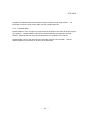
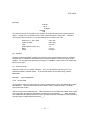
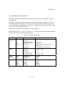
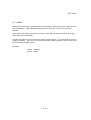
Robots do work in place of people. For example, let’s say that somebody has to attach a part to a
workpiece coming down a conveyor. The employee takes a part from a parts bin and attaches the
part to a workpiece transported to his or her station by a conveyor. If we were to set up a robot to
do this work instead, we would have an arrangement something like that shown in Figure 1.1.
Parts feeder
Wokpiece
Conveyor
Fig. 1.1 Assembly work
Here, the robot grabs a part from the parts feeder and attaches the part to a workpiece coming
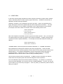
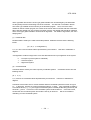
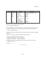
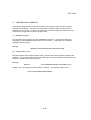
down the conveyor. considering this work from the point of view of the robot (and not, for example,
from the point of view of the parts feeder or conveyor), we would come up with a diagram like that of
Figure 1.2. In this Figure, the robot first moves straight down from Point B to Point A, where it
grabs a part. After grabbing the part, the robot moves back up from Point A to Point B. From
Point B, the robot moves the part to Point C, which is directly above the part attachment location
Point D. The robot then drops down from Point C to Point D, and attaches the part to the
workpiece. When the robot is finished attaching the part, it moves back up to Point C, and then
finally back to Point B. This completes one work cycle.
- 1-1 -
STE 58762
B: Position just above A
C: Position just above D
D: Position where a part is mounted.
A: Position where robot grips a part.
Fig. 1.2 Robot movement
- 1-2 -
STE 58762
1.2 ROBOT LANGUAGE
Robots do assembly work and other tasks in place of people.
However, someone still has to teach the robot what to do.
Robots will only do what you tell them to do, and it's
important to tell them exactly what you want it to do.
Telling a robot what to do is called "teaching." Making a robot do what you taught it to do is called
"playback." Of course, this only applies to what are called "playback robots," which repeat (or
playback) the movements you instructed the robot when teaching. Toshiba SR Series robots are
playback robots.
There are various ways to teach a robot what to do. One way is to physically move the robot
through the work cycle (while, of course, the robot is in the teaching mode). The robot remembers
the locations where it was moved and, in the playback mode, retraces this path and performs the
work. This is the usual method for teaching painting robots and spot welding robots.
However, things get more complicated when dealing with peripheral devices (such as a parts
feeder or a conveyor belt). In such a case, you must coordinate the movements of the robot with
the movements of the peripheral devices. In the previous example, we talked about a robot
attaching a part to a workpiece coming down a conveyor line. However, what if we want to attach
different parts to different workpieces? What do we do if the robot misattaches the part and we
want to try again?
In order to tell the robot what to do, we need to express robot actions in terms the robot
understands. This is the purpose of robot language. A robot language is nothing more than a set
of words describing robot actions. An arrangement of these words used to control the movement
of the robot is called a program. Writing a program is called programming.
There are various robot languages in existence. However, SR Series robots use SCOL (Symbolic
Code Language for Robots), a language developed specifically for robots. Therefore, we will limit
our discussion of robot languages to SCOL in this Manual.
- 1-3 -
STE 58762
If we were to write a program in SCOL for the previous example (in which we attach a part from a
parts feeder to a workpiece on a conveyor), it would look like this:
PROGRAM ASSEMBLY
MOVE B
OPEN1
MOVE A
CLOSE1
DELAY
0.5
MOVE B
MOVE C
MOVE D
OPEN1
DELAY
0.5
MOVE C
MOVE B
END
Move to Point B.
Open Hand 1.
Move to Point A.
Close Hand 1.
Wait 0.5 seconds before grabbing the part.
Move to Point B.
Move to Point c.
Move to Point D.
Open Hand 1.
Wait 0.5 seconds before letting go off the part.
Move to Point c.
Move to Point B.
The word PROGRAM marks the beginning of a program and the word END marks the end of a
program. The name of this particular program is ASSEMBLY. The commands should not be too
hard to understand. MOVE A means to move to Point A. OPENi and CLOSE 1 mean to,
respectively, open and close Hand 1. (There are two hands.) DELAY 0.5 means not to do
anything for 0.5 seconds. Furthermore, the locations of Points A, B, C and D are defined (taught)
beforehand by physically guiding the robot (in the teaching mode) to these points. (To put it
another way, the location of these points is not defined by the program itself.)
By arranging a series of commands in the order that you want things done, SCOL allows you, the
programmer, to express just what the robot is supposed to do in terms that the robot understands.
- 1-4 -
STE 58762
1.3 TYPES OF COMMANDS
In the previous section, we saw how SCOL is used to express the action of the robot.
Here, we explain a little bit more about SCOL commands themselves.
In addition to commands like "MOVE A" which actually move the robot, there are many other
commands which do such things as send signals to other equipment (such as conveyors, parts
feeders, process computers, etc.) or direct the robot to do the same thing over and over again.
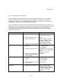
Table 1.1 presents a list of SCOL commands.
All SCOL commands can be roughly classified into one of six categories.
(1)
Movement control commands
These commands move the robot. Commands which temporarily stop the robot, interrupt
movement, or restart the robot are also included in this category. Commands which actually move
the robot are called movement commands.
(2)
Program control commands
Program control commands control the execution of the program by doing such things as executing
certain parts of the program in accordance with external signals or causing portions of the program
to be carried out repeatedly.
(3)
I/O (Input/output) control commands
These commands are used to read in (input) or send out (output) signals to and from external
equipment, such as the teach pendant. Data input/output of hand open/close communication
channel are included in the I/O control command.
(4)
Movement condition commands
These commands are used to specify the configuration and speed of various joints of the robot
while it is moving.
(5)
Calculator commands
These commands are used to invoke (use) mathematical functions such as the trigonometric
functions (sin, cos, etc.) and the square root function.
- 1-5 -
STE 58762
(6)
Movement reference commands
These commands are used to reference and check the movement of the robot. For example,
these commands could be used to determine what percentage of a certain motion has been
completed at a certain time. By including these commands in your program, you can set timers
and make sure robot motions do not interfere with each other.
These commands are meant to be used in combination with other commands in your program. By
skillfully placing such commands in the right places, you can, for example; (1) Get the robot to send
out a signal to an external device when the robot has completed 70% of a certain motion. (2)
Should one motion not follow another motion within a certain period of time, have the program
branch off to an error loop.
Type
Movement control commands
Purpose
(1) Move the robot.
MOVE, MOVES, MOVEC,
MOVEA, MOVE1, READY
(2) Temporarily stop the robot.
DELAY
(3) Move the robot hand.
OPEN1, OPENI1, OPEN2,
OPENI2, CLOSE1, CLOSEI1,
CLOSE2, CLOSEI2, UP,
DOWN, TURNL, TURNR
BREAK, RESUME, PAUSE
(4) Interrupt or restart operation.
Program control commands
(1) Monitor external signals,
timers, etc.
ON ~ DO ~,
IF ~ THEN ~ ELSE,
WAIT, IGNORE
(2) Control program execution.
PROGRAM, GOTO, RCYCLE,
RETURN, FOR ~ NEXT, STOP,
END
TASK, KILL, SWITCH
REMARK
(3) Make remarks (comments)
to aid in program debugging
and modification.
I/O control commands
Commands
(1) Input and output of externa
l signals.
DIN, DOUT,
PULOUT, RESET,
BCDIN, BCDOUT
Movement condition
commands
(2) Input and output of commu
nication data.
PRINT, INPUT
(1) Specify conditions for
controlling robot movement.
CONFIG, ACCUR, ACCEL,
DECEL, SPEED, PASS,
TORQUE, GAIN, ENABLE,
SETGAIN, DISABLE, NOWAIT,
PAYLOAD, FREELOAD,
SWITCH
- 1-6 -
STE 58762
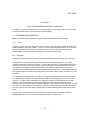
Type
Calculator functions
Purpose
(1) Perform calculations for real
numbers.
(2) Perform calculations
involving positional and
coordinate data.
Movement reference
commands
Commands
SIN, COS, TAN, ASIN, ACOS,
ATAN, ATAN2, SQRT, ABS,
SGN, INT, REAL, LN, MOD,
LOGIO, EXP, AND, OR, NOT
HERE, DEST, POINT, TRANS
(3) Use an array.
DIM, AS
(1) Check robot movement.
MOTION, MOTIONT, REMAIN
(2) Check system movement.
REMAINT, TIMER, MODE
(3) Assign a coordinate
TOOL, BASE, WORK
system.
Others
(1) Define a variable.
GLOBAL, END
(2) Restore an updated value in
the program file.
RESTORE
- 1-7 -
STE 58762
CHAPTER 2
WRITING PROGRAMS IN ROBOT LANGUAGE
In Chapter 1, we got a rough idea of what a robot language is and how it works.
2, we will describe how to write a program in robot language.
2.1
Now, in Chapter
PROGRAM CONFIGURATION
Below we present a general outline of program configuration with the SCOL language.
2.1.1
Files
In order to get the robot to perform a task, you need both a program written in robot language and
positional data for use by the program. That is, for each job you want the robot to do, you have to
have a matched set of a program (or programs) and data. This matched set is called a file.
Program editing, execution, saving and loading are all done in units of files.
2.1.2
Program
A program is an arrangement of words in robot language that tell the robot what you want it to do.
A program may "call" (use) other programs from inside of the original program. The original
program is referred to as the main program. These other programs are called subprograms since,
from the point of view of the main program, they are secondary. It is often convenient to make
sub- programs for sequences that are used often or for sequences that are more or less selfcontained. These subprograms can then be called when you need them. Subprograms save you
the trouble of having to write the same thing many times and, if used properly, can make your job a
lot easier.
You can include many programs in a single file. Unless you specify differently (in the command
lines at beginning of the file), the robot will assume that the first program in your file is the main
program. In order to call a subprogram, the subprogram must be in the same file as the main
program. Also, just because you may have several programs lined up in the file does not
necessarily mean that all the programs will be executed. As far as the robot is concerned, its job is
over when the main program is completed (i.e., when the robot reaches the final END statement of
the main program), and if the other programs have not been called by that time they will never be
called.
A plural number of programs can be executed at the same time, using the TASK command
(multitask execution). For details of the multitask execution, see Para. 2.8.
- 2-1 -
STE 58762
Programs are edited with the teach pendant using the controller screen editor function. For
information on how to use the screen editor, see the "operating Manual."
2.1.3
Positional Data
Positional data for use in a program (or programs) must be placed in the same file as the program
(or programs). Positional data in a file can be accessed (used) by all programs in that file.
However, positional data in a file cannot be accessed by any programs not in that file.
Positional data is "fed" to the robot using the data editor function of the controller. See the
operating Manual for information on how to use the data editor.
- 2-2 -
STE 58762
2.2 CHARACTER SET
The SCOL character set is made up of alphanumeric characters and the following special symbols.
Alphanumeric characters
ABCDEFGHIJKLMNOPQRSTUVWXYZ
abcdefghijklmnopqrstuvwxyz
1234567890
Special symbols
“‘()+-*/,.<>=
![]()%^&?
With the exception almost all of the small letters, these characters and symbols can all be input
from the teach pendant. When executing a program, the robot makes no distinction between
capital letters and small letters. For reading method of symbols, see "Appendix E."
- 2-3 -
STE 58762
2.3
IDENTIFIERS
In the SCOL robot language, identifiers are used to express commands, program names, variable
names, and labels (which are used to specify program branches). Identifiers must start with an
alphabetic character, although alphabetic
characters, numerals, or any combination of the two may follow. There is no particular limit on
length, although the robot will only differentiate the first ten alphanumeric characters. The robot
does not care whether you use capital or small letters, since it will treat them the same anyway.
For example, as far as the robot is concerned, all four of the following are the same:
TOSHIBAROB
toshibarob
TOSHIBAROBOT
toshibarobot
With a few exceptions, small letters cannot be input from the teach pendant. Also, you cannot use
any special symbols or include any spaces in the names for identifiers. (Instead, special symbols
or spaces are used to separate identifiers.) For example, the robot will consider the following as
different:
TOSHIBAROBOT
TOSHIBA ROBOT
“TOSHIBA ROBOT” will be interpreted as two different identifiers, i.e., TOSHIBA and ROBOT.
Some identifiers have already been defined by the SCOL language itself. These are called
reserved words, and you as the programmer cannot use them for any other purpose except for that
already defined. (For example, PROGRAM is a reserved word used to tell the robot when a
program will follow. Therefore you cannot, for example, go and call one of your variables
PROGRAM since the robot will have no idea of what you are talking about.)
A list of reserved words is shown in Appendix B. In addition to SCOL commands, you will find
words used in the computer system and words set assigned for future expansion.
Do not use identifiers with the same name for different meanings. For example, if you decide to
call your program GEORGE, do not go and name any variables GEORGE. If you do, you may get
an error when you try to execute your program. At the very least, you will be sorry when it's time to
debug your program.
- 2-4 -
STE 58762
2.4
VARIABLES AND CONSTANTS
Not all data takes the same form, and these different forms of data are called data types. Scalar
type (integer type, real number type and character string) and vector type (position type, coordinate
type and load type) can be used in the SCOL language. Variables are divided into global variable
and auto variable according to the definition method. All taught data and variable defined in the
area between GLOBAL and END are called the global variable. These variables can be referred
and changed from any part of the program. For all data types of global variables, the array can be
declared. For descriptions of global variable and array, see Para. 2.8.5.
The work area in the controller is used for all data. The defined value is substituted for the global
variables value at the start of the program, except for the array without a specific initial. If the
value is entered for the variable during program execution, only the work area is changed. If the
power of controller is turned off, execution file is reselected or the file is edited, work area is reset by
the variable’s initial value saved in the file and the changed value is lost accordingly. This is also
applicable for change of the taught data. If the data in the file is to be overwritten, the RESTORE
command should be executed in the program.
2.4.1
Scalar Data
There are three types of scalar data, i.e., integers, real numbers and character strings. Scalar type
auto variables can only be used in the program in which they were declared. That means that if
you use a variable with the same name in another program, the two variables will be completely
independent and have nothing to do with each other. Therefore, when passing data from one
program to another, make it a point to, if possible, redefine the variable as the scalar type global
variable or declare the arguments in the program. (If you did not understand this too well, refer to
Section 2.8 "Programming.")
(1)
Integer data
(a)
Constants
SCOL can handle integer values ("whole numbers") in the range of - 2147483648 to + 2147483647.
When an integer is used as a constant in a program, if it is positive, directly describe the value; if it
is negative, describe the value following the - symbol. Examples are:
0
234
-39208
5963
- 2-5 -
STE 58762
(b)
Variables
Variables are distinguished by identifiers and can be in the range of - 2147483648 to +
~147483647, just as above. The data type of a variable is determined by the data type of the first
number you assign to that variable. For example, if the first thing you assign to a variable is an
integer, all other numbers substituted into that variable will become integers. That means that if
you later try to insert a real number into this variable, the controller will chop off all the decimal
places and treat what is left as an integer.
The variable comes in two types; the global variable which is valid in the entire program and the
general variable which is valid in a part of the program. The global variable can be changed from
any part of the program.
(c)
Logical values
Logical values are used in the program when making conditional judgments. Logical expressions
and commands such as DIN (which check input signals) return logical values.
A logical value may have one of two values; TRUE or FALSE. Internally, logical values are treated
as integers with 1 being TRUE and 0 being FALSE.
Note)
(Strictly speaking, 0 is considered as FALSE and everything else is considered as TRUE.)
(2)
Real data
With SCOL, numbers are treated as real types with the exception of certain special cases.
(a)
Constants
SCOL can handle real numbers having an absolute value in the range of approximately 5.87 x 10-3.9
to 6.80 x 1038. This range can also be expressed as 2-127 to ((223 - 1) x 2106). The number
significant digits for the mantissa [the mantissa is the part of the number to the right of the decimal
point) is approximately 7 in Base 10. (The precision is 223).
When a real number is used in the program, if it is positive, directly describe the value; if it is
negative, describe the value following the - symbol.
When the decimal part is 0, it is omissible. However, when the decimal point is omitted, the data
are treated as integer type data. In addition, since the integer part cannot be omitted, even if the
absolute value of a numeric value is less than 1, it is necessary to designate 0 to the integer part.
- 2-6 -
STE 58762
Example)
1234.567
-28.16
0.00985
1234567.
-369.
As mentioned above, the precision of the computer is somewhat limited when handling decimal
values. Usually this is no problem if the number of decimal places is reasonable. Therefore,
when working with the robot, try to use the following as the minimum set units.
Distance (x, y, and z data)
Angles (C data)
Time
Rates (Speed, torque, etc.)
Mass
Inertia
0.001 mm
0.001 deg.
0.01 sec.
1%
0.01 kg
0.01kg.m
(b) Variables
Variables are distinguished by identifiers and have the same range as listed above for constants.
The data type of a variable is determined by the data type of the first number you assign to that
variable. For example, if the first thing you assign to a variable is a real number, that variable will
become a real type.
(3) Character strings
Character strings can only handle constants. They are expressed by placing one or more
characters between quotation marks. In the example below, the character string is SCOL
MESSAGE.
Example)
2.4.2
"SCOL MESSAGE"
Vector Data
As opposed to scalar-type data which only holds one data element, vector-type data holds multiple
data elements. There are three types of vector data in SCOL; positional vectors, coordinate
vectors and load vectors.
Vectors hold one to five data elements. With commands such as POINT and TRANS which create
vector-type data, elements are expressed by enclosing them in brackets {___}. With commands
such as MOVE and TORQUE which use vector type data, elements are assigned and expressed by
enclosing them in slightly different brackets {___}.
- 2-7 -
STE 58762
Vector type data other than the vector type global variable such as data taught by the data editor
are temporarily stored in the working area of the controller. The data are not created in the file.
The vector type variable can be used only in the declared program. Thus, even if the same
variable is used in another program, the content of the former does not accord with that of the latter.
When data are passed from one program to another program, the passed data should be redefined
as the vector type global variable or it should be an argument. For details of arguments, see "2.8.2
Subprograms."
(1) Positional data
Positional data is used by the robot to describe positions. Positional vectors have the following
format.
(X, Y, Z, C, T, <configuration>)
X, Y, Z, C and T are coordinate values represented by real numbers. Units are in millimeters or
degrees.
<Configuration> holds an integer from 0 to 2 that describes the set-up configuration of the system.
0 ... Free (Set-up of the system is undefined)
1 ... Left hand system
2 ... Right hand system
(2) Coordinate data
Coordinate data is used by the robot to specify coordinate systems. Coordinate vectors have the
following format:
(X, Y, z, C)
X, Y, Z and C are coordinate values represented by real numbers. Units are in millimeters or
degrees.
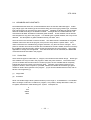
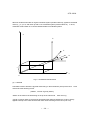
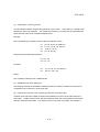
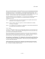
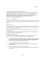
Coordinate vectors allow one to convert between different coordinate systems as shown in Figure
2.1. In the figure, we have an original coordinate system X, Y and Z. Then, with data provided by
a coordinate vector (x, y, z, c), the original coordinate system is shifted parallel along its axes by the
amounts x, y and z. This forms a new coordinate system centered about 0'. Once this is done,
we twist the new coordinate system around the Z' axis by an amount c. We are now finished
orientating our new coordinate system.
- 2-8 -
STE 58762
What we did above was take an original coordinate system (centered about 0), applied a coordinate
vector (x, y, z, c) to it, and came up with a new coordinate system (centered about 0'). In short,
coordinate vectors allow us to convert between different coordinate systems.
Z
Z’
Y’
Y
X’
O’
z
y
x
X
O
Fig. 2.1 Coordinate transformation
(3) Load data
Load data is used to define the physical loads acting on the end effector (hand) of the robot. Load
vectors have the following format.
{<Mass>, <Center of gravity offset>}
<Mass> is the mass of the load acting on the tip of the robot hand. Units are in kg.
<Center of gravity offset> is the amount representing the distance between the center of gravity
applied to the tip of the robot hand and the center of the tool flange of the robot (unit: mm).
- 2-9 -
STE 58762
2.4.3
System Variables
The SCOL language provides special variables that are used in the programs to specify and
referent robot operating conditions. These variables are called system variables. Just like other
variables, you can refer to these variables in the program, change their value, etc. However, you
have to be careful when setting or substituting values into system variables since doing this will
directly effect robot operating conditions.
A list of system variables is presented below in Table 2.1.
Table 2.1 List of system variables
Name
CONFIG
ACCUR
ACCEL
DECEL
SPEED
PASS
TORQUE
GAIN
TOOL
BASE
WORK
TIMER
ERROR
PLAYLOAD
SWITCH
TID
Note:
Description
Robot configuration
Positioning accuracy
Acceleration (during acceleration)
Deceleration (during deceleration)
Speed of movement
Short-cut movement parameter
Maximum torque on each axis
Servo gain on each axis
Tool coordinates
Base coordinates
Work coordinates
Timer
Error information
Load on the robot
Multitask
Effective values
0, 1, 2
0, 1
0 ~ max%
0 ~ max%
0 ~ max%
0 ~ 100%
0 ~ max%
0.1
0.1 sec.
0~
0, 1
1~
Maximum values are set separately for each system.
- 2-10 -
Initial value
0
1
100
100
100
100
300
1
0
0
0
0
1
-
Data type
Integer type
Integer type
Integer type
Integer type
Integer type
Integer type
Vector type
Vector type
Coordinate type
Coordinate type
Coordinate type
Real type
Integer type
Load type
Integer type
Integer type
STE 58762
Should you change the contents of a system variable related to movement control, that change will
not take effect until the next motion; it will have no effect at all on a motion in progress at the time;
However, by using a WITH construct, it is possible to temporarily set a system variable with regards
to one motion command. For example:
MOVE Al WITH SPEED = 50
Furthermore, be warned that SCOL does not check to see whether a value substituted into a
system variable is within the permissible range. Should the value not be in the permissible range,
SCOL will do one of two things:
•
Should you try to insert a value less than the minimum permissible value, the minimum
permissible value will be entered in its place.
•
Should you try to insert a value greater than the maximum permissible value, the maximum
permissible value will be entered in its place.
Refer to Chapter 3 for details on how to use system variables.
2.4.4
System Constants
In order to make programs easier to read (and thereby debug), SCOL provides the system
constants shown in Table 2.2. These names can be substituted into the program in place of
numbers in order to make it easier to see what you are doing. However, be sure to use them only
in the locations specified in the Comments column of Table 2.2. If you use them in other locations,
trying to debug your program can become a real nightmare.
Table 2.2 List of system constants
Name
FREE
LEFTY
RIGHTY
COARSE
FINE
OFF
ON
PAI
CONT
CYCLE
SEGMENT
Value
0
1
2
0
1
0
1
3.141593
0
1
2
Comments (Locations for use)
In the system variable CONFIG
In the POINT command
In the system variable ACCUR
In the system variable GAIN
In the SETGAIN command
Pi value
In the MODE command
- 2-11 -
STE 58762
2.5
MATHEMATICAL FUNCTIONS
This section describes the mathematical functions provided by SCOL for substitution, calculation
and judgement.
With SCOL, mathematical functions can either be used independently or included in a command.
A mathematical function included in a command may be a computational expression (in which the
result of a calculation is substituted into a variable), or a logical expression (such as greater-or-lessthan constructs and true/false constructs).
Mathematical functions provided by SCOL are shown in Table 2.3.
Note that 0/0 will return a -1, and 0 ^ 0 will return a 1. One would normally expect these operations
to return an error, but be careful because they don't.
Table 2.3 Mathematical functions
Type
Arithmetic
functions
Relational
function
Logical
operands
Functions
Operand
^
*, /
+, MOD
Function
Exponentiation
Minus sign
Multiplication, division
Addition, subtraction
Remainder
=
==
< >, > <
<
>
< =, = <
> =, = >
AND
OR
NOT
SIN
COS
TAN
ASIN
ACOS
Substitution
Equal
Not equal
Less than
Greater than
Less than or equal
Greater than or equal
Logical product
Logical sum
Negation
Sine
Cosine
Tangent
Arcsine
Arccosine
- 2-12 -
Example
A ^ B (A to the B power)
-A
A * B, A / B
A + B, A – B
A MOD B (The remainder when A is
divided by B.)
A = B (Puts the value of B into A.)
A==B
A < > B, A > < B
A<B
A>B
A < = B, A = < B
A > = B, A = > B
A AND B
A OR B
NOT A
SIN (A)
COS (A)
TAN (A)
ASIN (A)
ACOS (A)
STE 58762
Type
Functions
Operand
ATAN
ATAN2
SQRT
ABS
SGN
INT
REAL
LN
LOG10
EXP
Function
Arctangent
Arctangent
Square root
Absolute value
Sign
Changes number to an
integer.
Changes number to a
real number.
Natural logarithm
Common logarithm
Exponential to base e.
Example
ATAN (A)
ATAN2 (A, B) (Arctangent of A / B)
SQRT (A)
ABS (A)
SGN (A)
INT (A)
REAL (A)
LN (A)
LOG10 (A)
EXP (A)
Parentheses ( ) may be used inside the expressions.
2.5.1
Computational Expressions
In the SCOL language, the results of computations on the right side of an equal sign are placed in
the register (variable) on the left. Variables and constants may be used in the expressions.
(1) Order of computational priority
The SCOL language uses the same order of priority used by almost all other computer languages.
Specifically;
• When there are brackets, operations inside the brackets are done first.
• Otherwise, operations are performed in the order of: 1.
Assignment of negative signs, 2. Exponentiation, 3.
Multiplication and division, 4. Addition and subtraction
• Should the order of priority be otherwise the same, priority is assigned from the left of the
expression to the right.
For example:
a = b + c * d / (e - f) - g,
- 2-13 -
STE 58762
The order of computation for the above expression is:
1.Calculate e - f.
2.Calculate C * d.
3.Divide C * d by e - f.
4.Add the above result to b.
5.Subtract g from the above result.
e-f
c*d
(c * d) / (e - f)
b + (c * d) / (e - f)
(b + (c * d) / (e - f)) - g
Table 2.4 presents the order of computational priority for various operations.
Table 2.4 Order of computational priority
Priority
High
Low
Operation
Parenthesis
Assignment of vector elements
Assignment of negative signs and negations
Exponentiation
Multiplication, division, remainder
Addition, subtraction
Comparison
Equality, inequality
Logical product, logical sum
Substitution
Operand
( )
.
-, NOT
^
*, /, MOD
+, <, >, < =, > =,
= <, = >
= =, < >, > <
AND, OR
=
Note:
Explanation of grouping convention:
Left to right ... 1 + 2 - 3 is interpreted as (1 + 2) - 3.
Right to left ... NOT-3 is interpreted as NOT (-3).
- 2-14 -
Grouping convention
Left to right
Left to right
Right to left
Left to right
Left to right
Left to right
Left to right
Left to right
Left to right
Right to left
STE 58762
(2) Computation of scalar type data
Scalar type data can be used in calculations in combination with computational operands.
However, should even one number in an expression be a real number, the output of that expression
will also be a real number. Also, the following functions will all return a real number.
SIN, COS, TAN, ASIN, ACOS, ATAN, ATAN2, SQRT, REAL, LN, LOG10, EXP
When the variable on the left side of the equation is an integer type and the output of the calculation
is not an integer, the output will be converted into an integer before being assigned to the variable.
Do not forget, however, that all decimal points are chopped off when a real number is converted to
an integer. On the other hand, when converting from an integer to a real number, the number of
significant digits is limited. When you want to make it clear what kind of data type you are dealing
with, use the INT or REAL command.
Note that character strings cannot be used in calculations. Calculations may be carried out
between the elements of vector-type variables and scalar data. In this case, an element specifier
is appended to the end of a vector-type variable to specify the element which is involved in the
calculation. The value of the element is then drawn out from the vector-type variable and used in
the calculation.
As element specifiers, ".X", ".Y", ".Z", ".C" and ".T" may be used. You may also numerically specify
the element position with ".1", ".2", ".3", ".4" and ".5."
Examples:
A = POINT1.X/25
GAIN={GAIN. l,GAIN.2,0,0,0}
Note)
You can only use this to return the value of an element from the inside of a vector-type variable.
You cannot change the value of the element itself.
- 2-15 -
STE 58762
(3) Computation of vector-type data
You can add and subtract corresponding elements of two vectors. Computation is a possib1e only
between the same type variables. The <CONFIG> element is not involved in the calculations but
rather takes the value of the variable substituted into it.
Example:
Given the following two position vectors and two coordinate vectors;
P1: (10, 20, 30, 40, 50, RIGHTY)
P2: (-5, 10, -15, 20, -25, LEFTY)
C1: (100, 50, -50, 0)
C2: (12, 34, 56, 78)
and performing the following operations,
P3 = P1 - P2
C3 = C1 - C2
we obtain:
P3:
C3:
(15, 10, 45, 20, 75, RIGHTY)
(88, 16, -106, -78)
Notes)
The <CONFIG> element in P3 is indeterminant.
(4) Substitution into vector data types
The following methods are available to substitute (insert) a constant, a variable or the result of a
computation into an element of vector-type data.
(a) Commands to convert a row of scalar-type data into vector-type data
A POINT command and a TRANS command are available to convert rows of scalar data into a
vector data. POINT converts scalar data into positional vector data, and TRANS converts scalar
data into coordinate vector data. For details on how to use these commands, see "Chapter 3."
- 2-16 -
STE 58762
Examples:
P1 = POINT(P2.X, P2.Y, P2.Z + 50, 0, 0)
C1 = C2 + TRANS(100, 100)
The more alert reader may have noticed that something is missing in the second example. That is,
although the TRANS command is used to create coordinate vector types (which have four
elements), only two numbers (100 and 100) have been assigned in the command. This will not
cause any problems, however, since missing numbers will be assumed to be "0". Here, the
second example will be considered as:
C1 = C2 + TRANS(100, 100, 0, 0)
As you will recall, positional and coordinate vectors have the following format:
Positional data POINT (X, Y, Z, C, T <CONFIG>)
Coordinate data TRANS (X, Y, Z, C)
X, Y, Z, C and T are coordinate values represented by real numbers. Units are in millimeters or
degrees.
<CONFIG> stands for "configuration" and holds an integer from 0 to 2 that is used to describe the
set-up of the system.
0 ... Free (Set-up of the system is undefined)
1 ... Left hand system
2 ... Right hand system
Any omitted elements are taken as "0".
Note 1:
In order to make it clear just what kind of data type you are using, always try to use the POINT
command when creating positional type data and the TRANS command when creating coordinate
type data.
Note 2:
When position data which have not been taught are used in a program of the robot language, the
position data are temporarily stored in the controller memory. Thus, when the program is reset, the
position data are cleared. The position data are only valid in the program which uses data.
Therefore, to use the position data in a subprogram, it is necessary to pass it as an argument. For
details of arguments, see "2.8.2 Subprograms."
- 2-17 -
STE 58762
Note 3:
The substitution and reference to the array type data (type of variable name [index number]) are
dealt in the same manner as the original data type (scalar type and vector type) of the array type
data.
2.5.2
Logical Expressions
With SCOL, logical expressions can be used in combination with the commands IF, WAIT and ON.
Also, six relational operands are available (<, >, < = (or = <), > = (or = >), < > (or > <), and = =).
Also, logical expressions may be combined using the logical operands AND, OR and NOT. Scalar
constants, scalar variables and the results of calculations may be used as data in logical
expressions.
When evaluating equivalence, use the "= =" sign and not the "=" sign. When comparing real
numbers, differences of 0.001 or less will be ignored.
Logical expressions will return an integer value of 1 if true and 0 if false.
Examples:
1)
2)
IF K = =K2 * K3 THEN K = K2
ON MOTION > = 50 DO DOUT (1,2)
IF J1 THEN GOTO BRANCH1 ELSE GOTO BRANCH2
Let's take a look at the third example. If J1 is an integer 0 (or a real number with an
absolute value less than or equal to 0.001), the comparison will be considered as
FALSE. The program will then branch off to BRANCH2. Should J1 be anything
other than an integer 0 (or a real number with an absolute value more than 0.001),
the comparison will be considered as TRUE and the program will branch off to
BRANCH1.
- 2-18 -
STE 58762
2.6
LABELS
With the SCOL language, program branches are specified by labels placed at the beginning of the
branch destination. When labelling a statement as a branch, put a colon at the end of the
identifier.
When directing the program to branch to another location with the GOTO command, do not put a
colon at the end of the identifier.
Program branching may only be carried out within a single program. You cannot branch from one
program to another. Also, you may use the same labels in different programs, but you cannot use
the same label in a single program.
Examples:
LOOP1: MOVE P1
GOTO LOOP1
- 2-19 -
STE 58762
2.7
REMARKS AND COMMENTS
The SCOL language allows you add comments to your program in order to make it easier to
understand (and debug). Comments can be entered by using the teach pendant to type in
whatever you want to say. However, you have to use one of the following formats so that your
comments do not get mixed in with the program itself.
(1) REMARK command
You can write what you want to say after a REMARK command. The computer will ignore
everything from the REMARK command to the end of the line. This keeps your comments
separate from the program.
Example:
REMARK THIS PROGRAM WAS WRITTEN BY ME
(2) Single quotation mark
Everything written after a single quotation mark (') until the end of the line will be ignored by the
program. The nice thing about this method is that you can write comments on the same line as a
command to keep track of what is going on.
Example)
MOVE P1
'THIS COMMAND MOVES THE ROBOT TO P1
However, the ' mark does not have to follow a command. The following will also work:
'THIS IS A MEANINGLESS EXAMPLE
- 2-20 -
STE 58762
2.8
PROGRAMS
This section describes SCOL programs.
2.8.1
Program Declaration
A program has to have the following basic structure. If it does not, it is not a valid program.
PROGRAM <name of your program>
Contents of your program
END
A program is made up of everything from the PROGRAM statement to the END statement.
Write a program name after the PROGRAM statement. For example, if you want to call your
program "George," write PROGRAM GEORGE (and not PROGRAM <GEORGE>.) (Note,
however, that the program name becomes an identifier). Put the contents of your program
between the PROGRAM statement and the END statement.
Example)
PROGRAM SAMPLE
REMARK SAMPLE
SPEED=20
MOVE Al
DELAY 0.5
MOVE A2
DELAY 0.5
END
'Program name "SAMPLE"
'Comment
'Set the movement speed to 20% of the maximum speed.
'Move the robot to position Al.
'Wait for 0.5 sec.
'Move the robot to position A2.
'Wait for 0.5 sec.
'End of program
As shown in the example, the body of the program is composed of statements made up of an
arrangement of SCOL commands. A new line is created every time you push the "RETURN" (or
"ENTER") key when writing (or editing) the program. Up to 130 characters can be contained in a
single line. You may add spaces as you wish in order to make the program neater and easier to
read. Note how comments are entered with ' marks.
Note)
No spaces can be placed between characters structuring a word of a command and identifier.
- 2-21 -
STE 58762
2.8.2 Subprograms
You can call up a subprogram by just writing its name in the main program.
Example:
Here is a main program which calls a subprogram called SUB1.
PROGRAM MAIN
REMARK *** SAMPLE 1 ***
SUB1
END
Here is the subprogram which has been named SUB1.
PROGRAM SUB1
REMARK *** SUBPROGRAM NO. 1 ***
Body of subprogram
RETURN
END
A RETURN command should inserted in subprograms to send control back to the main program.
If you forget to write RETURN, SCOL will forgive you and pretend that there is a RETURN
command in front of the END statement.
When wishing to pass data between subprograms and the main program, you have to first specify
arguments for the subprogram. Arguments are like little "mailboxes" to which values passed
between the programs are sent and received. And, before using these mailboxes, you have to put
a name on each one so the postman knows whose mail goes where. When writing a subprogram
(not a main program), the program statement should be written like this:
PROGRAM <program name> (<names of arguments>)
After writing the program name, write the names of the arguments inside of brackets. Use
commas to separate the names of the arguments. (You cannot specify more than ten arguments
for a single subprogram.) For example, the main program will have the statement:
SUB EXAMPLE (A, B, C)
- 2-22 -
STE 58762
When calling the subprogram from the main program, write (in the main program) the name of the
subprogram and the data you wish to pass over to that subprogram. For example, the
corresponding subprogram will have the statement:
PROGRAM SUBEXAMPLE (M1, M2, M3)
The subprogram SUBEXAMPLE will now do whatever it does while treating A as M1, B as M2, and
C as M3.
Note that variables changed in the subprogram will automatically change the corresponding value in
the main program. For example, if M3 were to change in the subprogram SUBEXAMPLE, C will
also change simultaneously in the main program.
Example:
Main program
PROGRAM MAIN
REMARK *** SAMPLE 2 ***
K1 = 15
K2 = 28
SUB2(K1, K2, K)
PRINT K
END
Sub program
PROGRAM SUB2(N1, N2, N3)
REMARK *** SUBPROGRAM NO. 2 ****
N3 = N1 + N2
RETURN
END
In the above example, three arguments are being passed off between the main program and
subprogram. Specifically, K1 of the main program is passed over as N1 of the subprogram.
Similarly, K2 of the main program is passed over as N2 of the subprogram. The subprogram adds
N1 and N2, and puts the result in a variable called N3. When this happens, the value of K in the
main program also changes (since K and N3 correspond to each other).
- 2-23 -
STE 58762
When you execute this program, K1 will be passed off as 15 (to N1 of the subprogram) and K2 will
be passed off as 28 (to N2 of the subprogram). The subprogram will add these together and call
the result (which is 43) N3. The K variable of the main program will also change to 43. The
RETURN command will send control back to the main program, and the PRINT K statement will be
executed. This will cause the number "43" to be displayed on the teach pendant.
Note that subprograms may not call themselves. Also, should you call a subprogram which is in
another file, the controller will not understand you and instead will treat the name of that
subprogram as an error.
Note 1)
An expression itself, result of vector data expression such as position data and vector
data element can be designated as an argument.
Note 2)
When a constant is used as an argument, it cannot be substituted into a variable
according to a subprogram.
Note 3)
For a variable which is an argument to a subprogram, a value should be substituted into
the variable before the subprogram is executed.
2.8.3
Library
The SCOL language does not allow you to use subprograms which are not in the same file as the
main program. However, by putting especially useful subprograms in the library file (SCOL.LIB),
you can access these subprograms from all files.
Many useful subprograms have already been inserted in the library file including subprograms to
get the system ready and subprograms to operate the hand. Appendix C shows the contents of
the library file SCOL.LIB provided as standard on the robot controller system disk.
When writing your own subprogram to add to the library file, enter the program in that file just like
you would enter any other subprogram. For information on how to enter a program into a file, refer
to the Start-up Manual and the Operating Manual. Be sure to put any newly created files at the
very end of the existing library file.
Should a subprogram in the library file and a subprogram in the main file have the same name,
the controller will execute the subprogram in the main file (and not the subprogram in the library
file). The library is reloaded at program selection.
- 2-24 -
STE 58762
2.8.4
Multitask Processing
This paragraph describes how to use the multitask function of the SCOL language together with the
relevant commands and system variables.
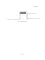
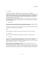
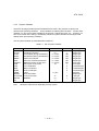
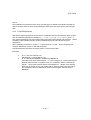
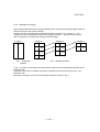
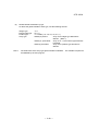
Program execution of single task and multitask operation is shown in Fig. 1 and Fig. 2. The
number in the figure designates the order of the program execution. Specific timing of changeover from program to program (task change) is described later.
Program
Program 1
Program 2
Program 3
A1
B1
C1
A2
B2
C2
A3
B3
A4
Fig. 1 Single task
operation
Fig. 2 Multitask operation
In Fig. 1, program A is executed continuously from the start to the end (single task operation and no
subroutine call).
A program which uses no multitask command is executed in the manner as shown in Fig. 1 (no
subroutine call).
Execution of a program which uses the multitask command is shown in Fig. 2.
- 2-25 -
STE 58762
As shown in Fig. 2, the multitask operation is realized, changing over a plural number of individual
programs by time sharing, as if the programs were executed in parallel. The order of program
execution is shown in the following table.
Order
1
2
3
4
5
6
7
8
9
10
11
12
13
:
Program to be executed
A1
B1
C1
A2
B2
C2
A3
B3
C1
A4
B1
C2
A1
:
Program 1 start
Program 2 start
Program 3 start
1-cycle end of program 3
1-cycle end of program 2
Program 3 start
1-cycle end of program 1
Program 2 start
Program 1 start
Next, the start of multitask is described.
A program that can be treated as multitask is the program block containing no arguments. The
program block means an area between the PROGRAM command and END command, which
consists of the SCOL language statements. The subroutine without argument can be dealt with as
a task. The argument cannot be kept in the task.
To deal with a program as task, use the TASK command. The TASK command executes a
program specified in the argument as a task. Unless the program starts by the TASK command,
the program is not performed as a task.
The program block (statements between the PROGRAM command and the END command)
described at the head of the program file is an exception. Even if the TASK command is not used,
the program is performed as a task.
To execute the program 2 as a task in the Fig. 2, the TASK (“PROG2”) is required to be executed in
the program 1. (The program 1 is described at the head of the file, and the program starts as a
task without TASK command.)
To execute the program 3 as a task, a new task (“PROG 3”) is required to be executed in the task
(in the program 1 or 2 in this case) which has been already started.
If the task and program which have been started are reset or the task operation is released by the
SCOL language, the task is kept active.
- 2-26 -
STE 58762
The task ID (the number assigned to the task) is described.
The characteristic numbers (task ID) are assigned to the tasks which have been started by the
TASK command respectively. In the example of Fig. 2, “1” is assigned to the program 1, “2” is
assigned to the program 2 and “3” is assigned to the program 3. This task ID starts from 1 in
sequence and this ID increases one by one every time the task starts (every time the task
executes). If the task is managed by the SCOL language, this task ID is used.
To get the task ID, see the following examples.
Example: I1 = TASK (“PROG 2”)
“I1” is a desired variable of integer type. The task ID of PROG 2 can be obtained. This command
is executed in the program 1. The task ID of its own cannot be referred to in the program 2 in this
example.
Example: I2 = TID
“I2” is a desired variable of integer type. If the system variable TID is referred to, the task ID of its
own can be acquired. If this command is executed in the program 2, the task ID of its own can be
seen in the program 2 (“2” in this occasion).
If this command is executed in the program 1, the task ID of program 1 (“1” in this occasion) is
substituted for “I2”.
If the task ID other than the own task is referred to from other tasks, variables of examples 1 and 2
are required to be defined as the global variable.
Change-over of task is described.
As shown in the Fig. 2, the system executes the program 1 ~ 3 by time sharing. When this
happens, timing of program change-over depends on the following three conditions.
(1)
When the program change-over is specified clearly by the SWITCH command of the SCOL.
The SWITCH command is used if the task is changed over clearly by the SCOL language.
Even if the task change-over conditions specified in the system are not satisfied while the
SWITCH command is used, the task can be changed over.
(2)
When a new task starts by the TASK command of the SCOL.
If a new task starts by the TASK command, the program control is changed over to the
newly started task.
(3)
When the task terminates by the KILL command of the SCOL.
If the task of its own terminates by the KILL command, the program control is changed over
to the next task.
- 2-27 -
STE 58762
(4)
When the predetermined conditions specified in the system are satisfied and the program is
changed over by the system.
The task change-over conditions specified in the system are as follows:
(1)
A program in a task is executed for more than 50 msec.
(2)
When the data area for movement command becomes full.
Up to four data can be read beforehand by the movement command. If this internal area
for prior reading becomes full, the task is changed over.
(3)
When the command requiring communication with an external device has been executed.
The INPUT, PRINT and RESTORE commands are not executed alone by the SCOL
program. They are the commands including such processing as the TP operation by an
operator and RAM file operation. If the system waits for a reply, therefore, the task is
changed over.
To avoid the task change-over by the system, set the system variable SWITCH to
“DISABLE”.
Note:
If the task change-over is prohibited, only currently active program is executed and the
other task program which has already started is not executed (single task operation).
2.8.5
Global Variable Definition
If the global variable which can be referred to from the entire program is defined, obey the following
rules.
(1)
Global variable declaration
If the global variable is used, the type and identifier (variable name) of the variable to be
used is required to be defined.
This definition must be performed before the first PROGRAM statement.
To define the variable A of real number type and the variable B of integer type, the definition
is as follows:
GLOBAL
A = 1.0 (This value is the initial value of the variable.)
B=2
END
PROGRAM
:
END
- 2-28 -
STE 58762
(2)
Global variable declaration by type
To define the global variable of each type, use the following formats.
Integer type:
Real number type:
Position type:
Array type:
Note 1:
A=1
B = 1.0
C = POINT (1.0, 2.0, 3.0, 4.0, 5.0, 1)
DIM D(10) AS INT
Array of ten integer type elements is
defined. (Note 1)
DIM E(10, 3) AS REAL
Array of 10 × 3 real number type elements
is defined.
DIM F(5) AS POINT
Array of five position type elements is
defined.
The initial value of the array type global variable is indefinite. The variable is required to
be initialized by the user program.
- 2-29 -