1
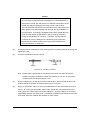
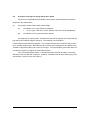
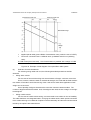
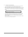
6 F 3 B 0 3 60
TOSLINE-S20
Active Star Coupler(ASC25)
Instruction Manual
REQUIREMENTS
• Keep this instruction manual where it can be easily
referred to by users and those responsible for the
equipment.
• Read this instruction manual carefully before using the
equipment.
• After this instruction manual has been read, keep it
beside the equipment.
Sep
TOSLINE-S20 Active Star Coupler (ASC25) Instruction Manual
6F3B0360
Table of Contents
1.
Introduction ...............................................................................................................3
2.
Overview ...................................................................................................................5
3.
System Configurations..............................................................................................7
4.
Outline of Functions ..................................................................................................9
5.
Specifications ..........................................................................................................11
6.
Hardware.................................................................................................................13
7.
6.1
Product construction...................................................................................13
6.2
External dimensions ...................................................................................13
6.3
Component identification ............................................................................14
6.4
Function setting switch ...............................................................................15
6.5
LED display.................................................................................................17
6.6
Optical connector........................................................................................18
6.7
Terminal block.............................................................................................19
6.8
Fuse holder .................................................................................................20
Start up and Power down methods.........................................................................21
7.1
Start up method ..........................................................................................21
7.2
Power down method ...................................................................................21
8.
Precautions on using Active Star Coupler ..............................................................23
9.
Installation and Wiring.............................................................................................25
9.1
Method for mounting the main unit.............................................................25
9.2
Connection of optical fiber cables (cords) ..................................................27
9.3
Optical parts................................................................................................28
9.4
Precautions on handling optical fiber and optical connector......................30
9.5
Method of optical connector assembly.......................................................32
9.6
Procedure of design for laying optical fiber cables ....................................36
TOSLINE S20
1
9.7
Precautions on ordering cables/cords ........................................................38
9.8
Precautions on laying cables......................................................................39
2
ASC25 Instruction Manual
TOSLINE-S20 Active Star Coupler (ASC25) Instruction Manual
1.
6F3B0360
Introduction
The brochure is an instruction manual for Active Star Coupler (ASC25) which is a
modified version of general use Active Star Coupler (ASC22). The Active Star Coupler (ASC25)
is specially designed to connect TOSLINE-S20 data communication network with a station
provided with F07 Type Optical Connector, such as TOSVERT-µ/S250W/W Drive Station.
Instruciton manuals for other TOSLINE-S20 components are listed below. System
designers, device designers, and maintenance personnel using a TOSLINE-S20 network should
refer to these manuals for information about how these components can be used in a TOSLINES20 network.
•
T2/T3 stations
6F3B0354
•
SIF (Serial Interface) station
6F3B0352
•
VME Bus station
6F3B0353
•
Loader software S-LS
6F3B0351
•
PLC-5 station
6F3B0355
•
Loader software S-LS (for windows)
6F3B0357
TOSLINE S20
3
4
ASC25 Instruction Manual
TOSLINE-S20 Active Star Coupler (ASC25) Instruction Manual
2.
6F3B0360
Overview
The Active Star Coupler is used for distributing fiber optic signals in a TOSLINE-S20
network.
The TOSLINE-S20 is a Bus-style transmission system. If the power is off in one of the
stations on this bus, communication is not possible before or after that station.
To prevent this from happening, an Active Star Coupler can be used.
If the Active Star Coupler is used, a station that is off will have no effect on the rest of the
transmission system. The Optical Connector Board of the Active Star Coupler has ten ports (CH1
through CH10), in which CH1 and CH10 adopt FC Type connector same to the general version of
Active Star Coupler (ASC22). Other ports, CH2 through CH9, adopt the JIS-F07 Type
connectors which are mounted to TOSVERT-µ/S250W/W drive station, etc.
Appearance of the Active Star Coupler is shown below.
Figure 2.1
TOSLINE S20
5
6
ASC25 Instruction Manual
TOSLINE-S20 Active Star Coupler (ASC25) Instruction Manual
3.
6F3B0360
System Configurations
Adoption of the Active Star Coupler provides a system configuration illustrated below.
(1)
Basic configuration
The maximum applicable number of F01 (FC) Type
connector stations is two.
The maximum applicable number of F07 Type
connector stations is eight.
F01: F01 (FC) Type station
F07: F07 Type station
Figure 3.1
(2)
Active Star Coupler daisy-shain connection
The maximum applicable
number of ASCs in daisychain connection is nine.
Figure 3.2
TOSLINE S20
7
8
ASC25 Instruction Manual
TOSLINE-S20 Active Star Coupler (ASC25) Instruction Manual
4.
Outline of Functions
(1)
Basic functions
6F3B0360
When the Active Star Coupler receives a signal from one channel among ten of them, it
tramsmits this signal (unchanged) from its remaining nine ports.
The drawing given below illustrates the case that data input from Port 1, and the data are
output from ports 2 through 10.
Data entered from Port 1
Data generated to Ports 2 through 10
Figure 4.1
(2)
Function of preventive measures to single-wire breaking
The function is effective to CH1 and CH10. Able/Disable of the function is selected by a
switch.
In the case that the function is brought into "Able" mode, the transmission on TX side is
stopped about 400 ms after the detection of wire breaking at RX side.
* On using the function, refer to 8.(1) "Precautions on the Preventive Measures to Single-Wire
Breaking".
(3)
Function of status display
Since the conditions of power source and of transmission are confirmed by the turning
ON/OFF of the respective LEDs, the function is useful in case of accident occurrence.
For detail of the display, refer to 6.5 "LED Display".
(4)
Function of optical level identification
Manipulation of switch makes the optical module output continuously illuminate. The
function is useful to check the optical level at terminals during the cable laying work.
For detail of the switch setting, refer to "6.4 Function setting switches".
(5)
Function of automatic test operation
The function is used in quality control in the production and test processes. During
normal operation, turn the switch to "OFF" position.
For detail of switch setting, refer to "6.4 Function setting switches".
TOSLINE S20
9
10
ASC25 Instruction Manual
TOSLINE-S20 Active Star Coupler (ASC25) Instruction Manual
5.
6F3B0360
Specifications
The section describes the specifications of the Active Star Coupler.
(1)
General specifications
General specifications of Active Star Coupler are given below.
Item
Voltage Rating
Specification
100/110 V AC, 50/60 Hz
200/220 V AC, 50/60 Hz
Fluctuation range 85 to 132 V AC, 47 to 66 Hz
170 to 250 V AC, 47 to 66 Hz
Power
Power consumption
about 10 VA
Supply
Retentive power interruption Resuming to normal operation within 10 ms
Insulation rating
1500 V AC for 1 minute
Fuse rating
250V-3A
Tempe- Operating
0 to +55°C (unit ambient temperature)
rature temperature
Storage
−20 to +75°C (unit ambient temperature)
temperature
20 to 90% RH, no condensation
Environ- Humidity
ment
Vibration
Conforming to JIS C0911
• Power OFF, Frequency 16.7 Hz, Displacement 3 mm
Atmosphere
Free from corrosive gas
Dust
Not more than 1 mg/m3
Ground
Grounding resistance 100Ω or less
External dimensions
390 (W) × 200 (D) × 70 (H) mm
Weight
approximately 3.0 kg
Cooling
Natural air cooling
Horizontal (unacceptable of upside down or vertical
Installation position
position)
Table 5.1
TOSLINE S20
11
(2)
Functional specifications
The functional specifications of the Active Star Coupler are listed below.
Item
Number of connectable
stations
Applied optical fiber
Transmission distance
Number of daisy-chain
connection of Star
Couplers
Connectable apparatus
Description
Max. 10
for FC Type
Silica glass optical fiber cable (JIS C6820)
connector
GI 50/125 µm (core dia./clad dia.)
for F07 Type H-PCF (hard clad silica glass core fiber) cable
connector
SI Model 200/230µm (core dia./clad dia.)
Station to Star Coupler
: Max. 1 km
Star Coupler to Star Coupler : Max. 1 km
Total system
: Max. 10 km
Max. 9
TOSLINE-S20 fiber optic network stations.
"ON" during normal operation
Contact rating
HEALTHY contact (Relay
Voltage: 250 V AC
Current: max. 1 A
contact)
Voltage: 24 V DC
Current: max. 1 A
Voltage: 5 V AC/DC Current: min. 10 mA
Table 5.2
12
ASC25 Instruction Manual
TOSLINE-S20 Active Star Coupler (ASC25) Instruction Manual
6.
6F3B0360
Hardware
The section describes the hardware of Active Star Coupler.
6.1
Product construction
(1)
Active Star Coupler main unit (1 unit)
Pet Name
: ASC25
Product Code
: SASC25*US
Target apparatus for connection
: TOSLINE-S20 fiber optic network stations.
(Various kinds of stations, ASC22, ASC25)
(2)
Fuse (2 pieces)
Rating: 250 V AC, 3 A
(One is attached to the apparatus, the other is for spare.)
(3)
L-shape bracket (2 units)
(Both are attached to the apparatus on shipment.)
6.2
External dimensions
External dimensions
Unit: mm
L-shape bracket
Figure 6.1
TOSLINE S20
13
6.3
Component identification
Names of the components of Active Star Coupler are given below.
Terminal block
Fuse holder
Optical connector
Status display LED
Function setting
-S20
Rubber feet
Figure 6.2 Front view of the unit
Name
Status display LED
(TX1 to 10, POWER, COMM)
Terminal block
Fuse holder
Optical connector (CH1 to 10)
Function setting switch
Use
Display of operational state
Power supply and Relay contact output
Protection of power supply
Fiber optic connection
Setting/releasing function
Table 6.1 Uses of components shown on the front face of the unit
14
ASC25 Instruction Manual
TOSLINE-S20 Active Star Coupler (ASC25) Instruction Manual
6.4
6F3B0360
Function setting switch
Arrangement and names of function setting switches are given below.
Figure 6.3
Name
TX1
TX10
OPTST
A.TST
Description
Setting the function of preventive
measures to single-wire breaking
Setting the function of preventive
measures to single-wire breaking
Setting the function for determining
optical power
Setting the function for automatic
testing
Use
Preventive measures to single-wire
breaking
Preventive measures to single-wire
breaking
Optical power determination
Quality assurance test
Table 6.2
(1)
Setting switch "TX1"
Turn the switch to "ON" position, and the function of preventive measures to single-wire
breaking of CH1 is actuated. In the case that, when the function is in "ON" mode, the RX signal of
CH1 cannot be detected during a period of about 400 ms, the transmission of TX signal from CH1
is stopped.
On the port which entered the stop transmission, when the switch is turned to "OFF"
position after the circuit operation is resumed, the transmission is reactivated on receiving signals
from other port. When the switch is turned to "ON" position again, the function is also reactivated.
When the function is in "OFF" mode, TX continues to transmit signals even if RX signal
cannot be detected.
(2)
Setting switch "TX10"
Turn the switch to "ON" position, and the function of preventive measures to single-wire
breaking of CH10 is actuated. In the case that, when the function is in "ON" mode, the RX signal
of CH10 cannot be detected during a period of about 400 ms, the transmission of TX signal from
CH10 is stopped.
TOSLINE S20
15
On the port which entered the stop transmission, when the switch is turned to "OFF"
position after the circuit operation is resumed, the transmission is reactivated on receiving signals
from other port. When the switch is turned to "ON" position again, the function is also reactivated.
When the function is in "OFF" mode, TX continues to transmit signals even if RX signal
cannot be detected.
* For TX2 through TX9, the ASC25 side does not have the function because the preventive
measures are provided to the connected device side.
(3)
Setting switch "OPTST"
Turn the switch to "ON" position, and the output side of the whole optical modules is kept
to illuminate continuously. Thus, the optical power can be determined. During the optical fiber
cable laying work, check that the satisfaction of the level requirements at terminals of optical fiber
cables, as needed, using the function. (Refer to page 30.)
Turn the switch to "OFF" position, and the mode returns to normal operation mode.
(4)
Setting switch "A.TST"
The switch is a function switch used in the product inspection of Active Star Coupler
before shipment.
When the Active Star Coupler is used, confirm that the switch is in "OFF" position.
Although no mechanical failure occurs when the switch is in "ON" position, the apparatus
cannot be operated in normal state.
* Inquiry relating to (4) is not accepted.
16
ASC25 Instruction Manual
TOSLINE-S20 Active Star Coupler (ASC25) Instruction Manual
6.5
6F3B0360
LED display
Status display LEDs are found on the front panel of the unit of Active Star Coupler.
Through these LEDs, the operating status of Active Star Coupler is identified.
(1)
Display and name of LED
Arrangement and names of LEDs on the front panel of ASC25 are shown below.
R
M E
1 2 3 4 5 6 7 8 9 10 M W
O O
C P
Figure 6.4
(2)
Description
Description of LEDs is given below.
Name of LED
POWER
COMM
TX1 - 10
Description
Normal/Abnormal of power supply to the Active Star Coupler are displayed.
Turned ON : Normal
Turned OFF : Abnormal
¡: State of absence of power supply
¡: State of fuse blown
Indicating the power source "ON" of Active Star Coupler and the
acceptance of data from station.
Turned ON : Normal
Turned OFF : Abnormal
¡: Power source of Active Star Coupler is "OFF".
¡: Power source of whole stations is "OFF".
¡: Transmission cables from whole stations are broken.
¡: No station is connected.
Indicating transmission mode on each port.
Turned ON : Transmitting
Turned OFF : Not-transmitting
Table 6.3
TOSLINE S20
17
6.6
Optical connector
For the transmission cables of the Active Star Coupler, the optical fiber cables (cords) are
used.
(1)
Position and name of optical connector
The Active Star Coupler has ten optical connector connection ports, CH1 through CH10.
They are positioned on the front panel of the unit: CH1 and CH10 are FC Type connectors, and
CH2 through CH9 are F07 Type connectors.
(2)
Connection cable
•
for FC Type: (CH1 and CH10)
Optical fiber cable: Silica Glass GI optical fiber cable (core diameter 50 µm, clad
diameter 125µm)
•
for F07 Type: (CH2 through CH9)
Optical fiber cable: H-PCF (hard clad Silica Glass SI optical fiber cable (core
diameter 200 µm, clad diameter 230µm)
(3)
Connection of cables
Connection is made between FC Type connector and FC Type connector, and between
F07 Type connector and F07 Type connector.
For more detail, refer to "9. Installation and wiring".
(Note) Sinse all ports have no priority among them, arbitrary one may be used. Nevertheless,
when the daisy-chain connection between ASC25s is done, use CH1 and CH10 (FC
Type). (Although CH2 through CH9 can establish the daisy-chain connection between
ASC25s without raising functional problems, the FC Type connector has a function of
preventive means to single-wire breaking and is able to function the preventive means to
single-wire breaking between ASC25s, so that we recommend the use of CH1 and CH10.
18
ASC25 Instruction Manual
TOSLINE-S20 Active Star Coupler (ASC25) Instruction Manual
6.7
Terminal block
(1)
Power supply
6F3B0360
Connect the power supply cables to the power source terminal block (M3.5 screws) of
ASC25 using appropriate crimping terminals. Insufficient connection may damage the terminal
block. Do not supply the power source to other users via the power source terminal block.
Power source side
(e.g., Power source panel)
100 V AC/200V AC terminal
(exchange is not required.)
Class 3 grounding
Ground terminal
Monitor side (e.g.,
Annunciator, I/O panel)
HEALTHY contact terminal
(Max) 24V-1A
Figure 6.5 Connection of cables
(2)
HEALTHY contact
HEALTHY contact indicates abnormal state of power source and communication. The
following is the conditions of HEALTHY contact.
HEALTHY contact
Close
Open
Condition of HEALTHY contact actuation
Power supply is normal, and any one of 10 ports is in normal operation.
Power source is in "OFF" mode, or no port is connected.
Table 6.4 Condition of HEALTHY contact
Rating of HEALTHY contact
Voltage
Current
DC
24V
AC
250V
AC/DC
5V
1A (Max)
1A (Max)
10mA (Min)
Table 6.5
TOSLINE S20
19
6.8
Fuse holder
When power source is connected, and the POWER lamp of LED is not turned ON, fuse
may be blown. In that case, cut OFF the power supply, and replace the fuse in the fuse holder at
front panel of the Active Star Coupler. Then turn the power source switch to "ON" position, again.
Fuse rating:....................... 250 V-3 A
20
ASC25 Instruction Manual
TOSLINE-S20 Active Star Coupler (ASC25) Instruction Manual
6F3B0360
7.
Start up and Power down methods
7.1
Start up method
(1)
Connect power supply cables to individual stations which are connected to the Active Star
Coupler.
(2)
Connect the connecting station with the Active Star Coupler, or an Active Star Coupler
with another Active Star Coupler (in the case of daisy-chain connection), using respective
transmission cables.
(3)
Set the operational mode switch.
(4)
Supply power to the Active Star Coupler and to each station.
(Note) Either of the two may be actuated first.
(5)
Begin the transmission to each station. (Refer to the instruction manual for respective
stations.)
(6)
Through the above-given steps, the Active Star Coupler begins its operation.
7.2
Power down method
(1)
Cut off the power supply to the Active Star Coupler and to each station.
(Note) Either of the two may be cut off first.
TOSLINE S20
21
22
ASC25 Instruction Manual
TOSLINE-S20 Active Star Coupler (ASC25) Instruction Manual
6F3B0360
8.
Precautions on using Active Star Coupler
(1)
Precautions on the function of preventive means to single-wire breaking
Observe the following-listed cautions on using the function of preventive mean to single-
wire breaking.
•
Even if the function is set, it is not actuated for about 10 seconds after power "ON".
•
In the case that the power is "ON" while the function was not set, when the function is set in
that state, (or when the switch is turned to "ON" position), the function is not actuated for
about 10 seconds after the switch is turned "ON", and after that, the function is actuated.
•
In the case that ASC25s are connected in daisy-chain, (in the case of CH1 and CH10 are
used), the actuation of the function that brings the resume operation between ASC25s
becomes troublesome. Accordingly, in normal operation, we recommend to not use the
function. Nevertheless, for a special case (e.g., the system operation is required to continue
even under wire-breaking between ASC25s), the function may be actuated based on the
judgment during system design.
(2)
General precautions for the Active Star Coupler
•
Do not remove the unit cover.
•
On using the optical fiber cables, care should be paid not to contaminate the edge faces of
the optical connectors. Since the optical parts have finely finished structures, care should be
given not to apply shock and unnecessary force to the parts. For handling and cleaning of
optical parts, refer to the "Installation and wiring" of the instruction manual.
•
Optical connectors of ports not in operation shall be provided with respective covers.
The mark indicates "DANGER". The label is attached to the portions that may
induce injury.
The precautions on the places around the terminal block with the
mark are the
following.
•
The protective cover on the terminal block at front face of the unit has sharp corners. Special
care should be paid for handling the cover.
•
During power acceptance to the Active Star Coupler, skin contact to the terminals on the
terminal block may induce electrical shock. Therefore, the protective cover shall be firmly
attached. During power acceptance to the Active Star Coupler, do not touch the terminals.
TOSLINE S20
23
24
ASC25 Instruction Manual
TOSLINE-S20 Active Star Coupler (ASC25) Instruction Manual
9.
Installation and Wiring
9.1
Method for mounting the main unit
6F3B0360
The Active Star Coupler may be installed within a cubicle, on a table, or onto a panel.
(1)
Installation in a cubicle
Cubicle
Active Star Coupler
L-shape
bracket
Base for the unit
Support for the unit
Unit: mm
Figure 9.1 Installation of Active Star Coupler in a cubicle
Using L-shape brackets and M5 screws (12 to 20 mm in length), mount the Active Star
Coupler main unit to the base for the unit.
In that case, remove the rubber feet at the bottom of the Active Star Coupler. The Lshape brackets have already been attached to the main unit of Active Star Coupler.
(2)
Installation on a table
For the case of installation of Active Star Coupler on a table, place the Active Star Coupler
on the table. The Active Star Coupler is equipped with rubber feet at the bottom. If the attached
L-shape bracket is unwanted, remove them by detaching the screws at the sides of the main unit.
After removing the L-shape brackets, retighten the once detached screws.
(Note) Do not stack the Active Star Couplers because the Coupler is not designed to have
strength bearing that weight.
TOSLINE S20
25
(3)
Mounting Active Star Coupler onto a panel
For panel mounting of the Active Star Coupler, horizontal mount shall be applied using
the L-shape brackets. Do not mount the Active Star Coupler upside down or vertical position.
When the mounting of the Active Star Coupler is made by using the L-shape brackets,
remove the rubber feet at bottom of the main body.
Mounting position is illustrated below.
Horizontal mounting
Top face
Figure 9.2 Recommended mounting position
Vertical mounting
Upside down mounting
Bottom face
Top face
Figure 9.3 Forbidden mounting position
26
ASC25 Instruction Manual
TOSLINE-S20 Active Star Coupler (ASC25) Instruction Manual
9.2
6F3B0360
Connection of optical fiber cables (cords)
Connection is made between FC Type connectors, or between F07 Type connectors. For
the case of CH1 and CH10, the connectors are FC Type, so that a transmission connector (TX) of
the Active Star Coupler shall be connected to the FC Type receiving connector (OR) on the target
station, and that a receiving connector (RX) of the Active Star Coupler shall be connected to the
FC Type transmission connector (OT) on the target station, using respective optical cables.
For the connection between Active Star Couplers, a transmission connector (TX) of an
Active Star Coupler shall be connected to a receiving connector (RX) of another Active Star
Coupler, further a receiving connector (RX) of an Active Star Coupler shall be connected to a
transmission connector (TX) of another Active Star Coupler, using respective optical cables.
(Notes)
•
At Active Star Coupler side, arbitrary port among CH1 through CH10 may be selected. (TX
and RX of CH1 and CH10 are in a pair form.)
•
To the optical transmission/receiving sections (ports) which are not connected with cables
shall be applied with black caps to avoid incoming ambient natural lights. Unnecessary lights
may induce error-functioning.
F07 Type station
Active Star Coupler
FC Type station
Figure 9.4 Method for connecting an Active Star Coupler with stations
Active Star Coupler
Active Star Coupler
Figure 9.5 Method for connecting Active Star Couplers
TOSLINE S20
27
9.3
Optical parts
(1)
Optical fiber cable
For the optical parts of FC Type, refer to the "T2/T3 stations of the instruction manual
(6F3B0354)". The following is the description on optical parts of F07 Type.
As the optical fiber cable, use H-PCF (Hard Plastic Clad silica glass optical Fiber) cable
that satisfies the following-given requirements.
Environmental condition
Optical fiber core wire
Temperature
−20°C to +70
Humidity
95%RH (60°C)
Core
Clad
Housing
Cable characteristics
Allowable tension
not more than
(max.)
75 kg
Allowable bending
not less than
radius (min.)
50 mm
Outer diameter
10.0 ± 1.0mm
Weight
100kg/Km
Outer diameter
200 ± 5µm
Material
Silica glass
230 (+0, −10) µm
Outer diameter
Material
Fluoroacrylate resin
Outer diameter
Material
500 ± 100µm
Fluororesin
Nominal NA
0.40
Wavelength
810nm
Transmission loss (max.)
7.0dB/Km
Transmission band width
14MHz ⋅ Km
(max.)
Table 9.1 Characteristics of optical fiber cable
We recommend the use of a short wave service H-PCF cable that is described below.
Manufacturer: Sumitomo Electric Industries, Ltd.
Agency: Takachiho Electric Co., Ltd.
Product identification: 2001H - MM - ¨¨ / ¨¨¨¨ 2 - C - LAP 2XCCV - HC - 20/07
Connector
Product name
Size
Cable total length (m)
Cord exposure length (m)
Both sides "male"
28
ASC25 Instruction Manual
TOSLINE-S20 Active Star Coupler (ASC25) Instruction Manual
(2)
6F3B0360
Optical fiber cord
Any type of optical fiber cords may be applicable if only they have the transmission
characteristics of optical fiber cable, given above, and they are connectable with F07 Type
connector, further they have the following-listed mechanical strength characteristics.
2.2 ± 0.2 × 4.4 ± 0.4mm
Outer diameter (mm)
Weight (kg/km)
8
Allowable tension (kg)
max. 25
Allowable bending radius (mm)
min. 50
Table 9.2
That type of cord is used for connecting transmission modules inside of panel and for
connecting an optical fiber cable with a transmission module. We recommend the use of a H-PCF
cord that is described below.
Manufacturer: Sumitomo Electric Industries, Ltd.
Agency: Takachiho Electric Co., Ltd.
Model:
(A) Optical fiber cord with connector on one end. (¨¨ denotes cord length.)
2001H-M-¨¨¨¨ DCV-HC-20/07
DCV-HC-20/07
Optical connector CF-2001H
Cord length
Figure 9.6
(B) Optical fiber cord with connector on both ends. (¨¨ denotes cord length.)
2001H-MM-¨¨¨¨ DCV-HC-20/07
Cord length
Figure 9.7
TOSLINE S20
29
(3)
List of optics-related parts
Name
Model, Rating
Use
Optical fiber cable
2001H-MMnn/¨¨¨¨
(Main line cable)
(Standard optical fiber
2-C-LAP 2XCCV-HC-20/07
(¨¨ denotes cable total length.)
cable)
(nn denotes exposed cord length.)
Optical fiber cable with
2001H-M-¨¨¨¨ DCV-HC-
(Cord with connector on one end)
optical connector
20/07
(¨¨ denotes cord length.)
(Standard optical fiber
2001H-MM-¨¨¨¨ DCV-HC- (Cord with connector on both ends)
cord)
20/07
(¨¨ denotes cord length.)
Aligner (In-line adapter)
IAT-4000
(Connection of optical connectors)
Table 9.3
9.4
Precautions on handling optical fiber and optical connector
Since optical fibers are finely finished parts and are made of glass, handling of them shall
be done with special care emphasizing the following.
(1)
Do not damage and contaminate the edge faces of optical connector. Damage
or attached dust on the edge of optical connector increase the connection loss.
If the edge of optical connector is contaminated, remove the contaminants from
the edge.
Key to prevent insertion error
Edge
Figure 9.8 Edge position of F07 Type connector
30
ASC25 Instruction Manual
TOSLINE-S20 Active Star Coupler (ASC25) Instruction Manual
(2)
6F3B0360
For connecting an optical connector and an optical fiber, align the key seats, and insert
the connector until "click" sound is generated. Since the optical fiber has only 200 µm in
diameter, accurate insertion is necessary to avoid increase in connection loss.
(3)
To the optical transmission/receiving sections of the connector not in use, a black cap
shall be applied to avoid incoming ambient natural lights. Unnecessary lights may induce
error-functioning.
(4)
Do not forcefully bend an optical fiber cord.
Allowable bending radius of optical fiber cord is 50 mm or more.
(5)
Do not strongly pull an optical fiber cord.
Allowable tensile force of optical fiber is 25 kg. The allowable tensile force at the
attaching section with an optical connector is about 2 kg. Special care should be paid on
applying tension to the optical fiber cord.
* The figure with underline is applied to a temporary tension, and shall not be applied to
sustained tension mode.
(6)
Do not excessively tighten an optical fiber cord.
On clamping an optical fiber cord, do not apply excessively large compressive force.
Generally, the resistance to compressive force of optical fiber cord is about 100 kg/50
mm.
* The figure with underline is applied to a temporary compressive force, and shall not be
applied to sustained compression mode.
(7)
On wiring an optical fiber cord, apply clamp to avoid direct self-weight of the cord onto the
connector section.
Allowable weight applied to the connection section with an optical connector is 200 kg.
TOSLINE S20
31
9.5
Method of F07optical connector assembly
Assembly work of optical connector shall conform to the following-given steps.
For detail, refer to the instruction manual attached to the assembly tools.
Precautions of optical connector assembly work
On assembling an optical connector, observe the following-listed
precautions.
•
Prepare exclusive-use assembling tools for processing
optical connector.
•
A simple training is necessary for the understanding of the
use of the exclusive-use assembling tools and for the
assembling method of optical connector.
For detail, inquire to the cable manufacturer.
Recommended optical connector assembling tools
Manufacturer: Sumitomo Electric Industries, Ltd.
Agency: Takachiho Electric Co., Ltd.
Model of optical connector assembling tools: CAK-1062
(1)
Cut off about 110 to 150 mm of the edge portion of the optical fiber cable using a cutter
knife or other means, and inserts the optical fiber through the cord bush.
Optical fiber
110 to 150mm
Cord bush
Figure 9.9 Fiber cut off
(2)
Using a jacket remover (use the hole at 2.2 side of label indication), remove the housing
to about 45 mm in length. At that moment, the step between two housings shall be within
1 mm.
Housing
45±2mm
Figure 9.10 Removal of housing
32
ASC25 Instruction Manual
TOSLINE-S20 Active Star Coupler (ASC25) Instruction Manual
(3)
6F3B0360
Fold the tension member, and insert the collar through the jacket of optical fiber core wire
until the collar went under the cord housing. The collar shall be exposed from the edge of
housing removal by 1 mm or less.
Housing
Housing
Collar
Collar
Jacket
Tension member
is divided to two
equal portions.
max. 1 mm
Figure 9.11 Collar insertion
(4)
Jacket
Figure 9.12 Protrusion of collar
Using the jacket remover (use the hole at 0.5 side of label indication), remove the cover
(semi-transparent) of core wire of the optical fiber.
Housing
Core cover
Clad
max. 2 mm
Figure 9.13 Residual length of core cover
TOSLINE S20
33
Caution
To remove the core cover (0.5 mm in diameter, semi-transparent), if
the knife edge of jacket remover is damaged or if mal-manipulation of
the knife is occurred, the clad (0.23 mm in diameter, transparent) of the
optical fiber may be damaged (becoming cloudy in the surface).
The clad of H-PCF optical fiber is an important section that protects the
Silica glass core and that assures high strength and high reliability of
the optical fiber. Accordingly, damaged surface of the optical fiber may
result in break of fiber at that portion in the succeeding process or
during the manipulation of connector. Therefore, the clad shall be
confirmed to have no damage on the surface by giving inspection
described below before entering succeeding step, independent of
presence/absence of cloudiness.
(5)
Cut off the tension member by 5 to 6 mm using scissors, and bring a spring on through the
optical fiber cord.
(6)
Insert the optical fiber through a ferrule.
Ferrule
Spring
Figure 9.14 Insertion of ferrule
Note: Assure that the optical fiber is inserted into the ferrule until either the tension
member is folded to protrude to outside the ferrule by 1 to 2 mm, or the tension
member enters the ferrule by about 1 mm.
(7)
Using a crimping tool, fix the ferrule and the optical fiber. The work shall be done with
special care for the position of ferrule and the groove of the tool.
(8)
Using an optical fiber cutter, cut off the protruded portion of the optical fiber at the tip of
ferrule. On cutting the optical fiber, debris of the optical fiber may be attached to the
cutting edge of the fiber cutter due to static electricity. Check the debris on the cutting
edge before and after the cutting work. If the debris of optical fiber remained on the cutter
knife edge, remove the debris with tweezers or other means.
34
ASC25 Instruction Manual
TOSLINE-S20 Active Star Coupler (ASC25) Instruction Manual
(9)
6F3B0360
Assemble the optical connector. On assembling the optical connector, care should be
given not to mix the transmission side ferrule and the receiving side ferrule.
Plug-holding cap
Plug casing
Spring
Optical fiber
Cord bush
Projection
Hole
Figure 9.15 Optical connector assembly
(10)
Confirm the quantity of light using a light power tester or other means
Recommended optical power meter
Manufacturer: Hactronics Co., Ltd.
Agency: Hakuto Co., Ltd.
Model:
TOSLINE S20
photom 205
(light power meter)
photom 310-081CF
(light source unit)
photom 180-HTL
(F07 Type connector adapter)
35
9.6
Procedure of design for laying optical fiber cables
For the use of TOSLINE-S20 optical fiber cable system, following-listed items shall be
observed to lay cables/codes.
(1)
Precautions of optical fiber cable system design
(A)
Formulation of FC Type optical level diagram
•
(B)
For FC Type, refer to the "T2/T3 stations instruction manual (6F3B0354)".
Formulation of F07 Type optical fiber diagram
On designing an optical system, formulate the optical level diagram and confirm that the
light power has sufficient margin in advance. The following is an example of
transmission/receiving side level diagram. The example shows that the receiving side receives
up to -29 dBm of light power. Nevertheless, the receiving side is designed to be capable of min.
-25 dBm of light power taking into account of a margin. The level diagram given below does not
consider the presence of aligner at intermediate position.
If an intermediate aligner exists, a corresponding light loss shall be added. Generally,
that kind of loss is 2 dBm with an aligner. However, calculation shall be done after inquiry to the
manufacturer, (use the worst case values.)
36
ASC25 Instruction Manual
TOSLINE-S20 Active Star Coupler (ASC25) Instruction Manual
6F3B0360
Receiving side end
Transmission side end
Receivable range
Margin
•
Applied optical cable gives 6 dB/km of transmission loss, (under the use of H-PCF).
•
Connector connection loss is 1 dB/both ends, (2 dB/both ends for non-polishing
case).
At 7 dB of loss (the worst case), 1 km of transmission is possible with a margin of 4 dB.
Figure 9.16 Example of level diagram of an optical fiber cable system
(2)
Selection of terminal treatment
For selecting wiring cable and cord, the following-described precautions shall be
observed.
•
Wiring within cubicle
For the case of intra-cubicle wiring with several meters of length, cords are convenient.
Since, however, cords are weak in mechanical strength, the cords shall be fixed at about
two meters of intervals to avoid free-moving of the cords and to avoid direct application of selfweight onto a connector.
Use of plurality of aligners increases the connection loss and causes troubles. The
number of aligners shall be minimized. And, if the aligners are used, secure a margin on the light
level diagram.
•
Wiring outside cubicle
For the case of outside cubicle wiring, we recommend to use cables in view of durability.
The cable shall be a cord-integrated cable. On laying the cables at site, attach optical connectors
to the cables referring to "9.5 Method of optical connector assembly" and the technical documents
issued by the optical cable manufacturer.
TOSLINE S20
37
9.7
Precautions on ordering cables/cords
On ordering the cables and cords, the following-listed precautions shall be observed.
•
Cables and cords applied shall be those specified in the instruction manual.
•
When the cable contractor is named, and when the cables specified in the instruction manual
cannot be adopted, use the cables having the same characteristics with those specified in
the instruction manual. In that case, particularly the following-listed characteristics shall be
checked.
Core diameter/Clad diameter, Transmission band, Applied
wavelength, Aperture rate, Attenuation
* If the judgement is difficult to give, please contact our section in charge of the matter.
•
Cable contractors shall be unified. For example, separate the cable contractor and the
connector-mounting contractor should be avoided because there is no responsible
contractor on accident.
•
Delivery of optical fiber cables take a time compared with ordinary wire cables. Therefore,
order shall be made with a sufficient margin of time.
38
ASC25 Instruction Manual
TOSLINE-S20 Active Star Coupler (ASC25) Instruction Manual
9.8
6F3B0360
Precautions on laying cables
For handling optical connectors and cords, refer to the "7.4 Precautions on handling
optical fiber and connector" of the instruction manual.
(1)
•
Precautions on laying cables
For the case of cable with connector, the front end cord and optical connector portions shall
be carefully prepared not to apply direct force to the portions.
•
(2)
Cables shall be laid in straight pattern as far as possible.
Check of transmission loss
To monitor the connection condition of aligner after wired and to detect abnormality in
transmission loss caused from contamination on the connector edge faces, light power shall be
measured. The determination of the light power is done as follows.
Devices to be prepared
Light power meter
2 units (one shall have a reference light emission function)
Reference single-core cord 2 cords (each having a length of about 1 meters)
(A)
Check of light power meter
One of the two light power meters shall be used as the light source, and the two
shall be connected as shown in the figure below, thus confirm the light emission
power.
Light power meter (transmission side)
Light power meter (receiving side)
Reference single-core cord
Figure 9.17 Measurement of light emission power
Two reference cords shall be used to determine the light emission power.
Two cords for checking confirm that the reference cord is in normal state. Normally, both
cords give similar results.
(B)
Determination of transmission loss in actual optical transmission line
The above-described power meters shall be placed at both ends of the optical
transmission line to determine the transmission loss. The difference between the
value observed at that moment at receiving side and the value observed at
receiving side with the reference cord becomes the transmission loss in actual
transmission line.
Transmission loss in actual transmission line = (Observed value with the
reference cord) − (Observed value in the transmission line)
TOSLINE S20
39
The transmission loss in the transmission line is the sum of the transmission loss across
the optical fiber and the connection loss of aligner.
(C)
Comparison with level diagram
Comparing with the level diagram which was prepared during design stage, if the
transmission loss of the transmission line is abnormally large, the portion
structuring the transmission line should be abnormal. Thus, the inspection shall
be given to individual sections.
(3)
Check on system up
At the point of system up, check on the LED display status at each station to judge the
performance of normal transmission. For the meaning of display, refer to the instruction manuals
of individual stations.
40
ASC25 Instruction Manual