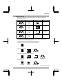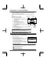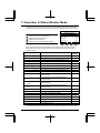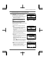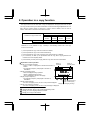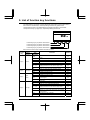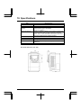
1
E6581323 ④ LCD Remote Keypad Instruction Manual RKP004Z Notice 1. Please see to it that this instruction manual reaches the actual user of the LCD remote keypad without fail. 2. Be sure to read this instruction manual carefully before installing and using the LCD remote keypad. After reading the manual, be sure to store it. Introduction Introduction Thank you for purchasing a LCD remote keypad (RKP004Z) designed specifically for Toshiba VF-AS1/PS1 series industrial inverters. The use of this LCD remote keypad (also referred to as the unit, the product and the remote keypad) equipped with a high-resolution liquid crystal display with back lighting makes it easier to set parameters or monitor the operation. The unit can be mounted easily on an inverter's operation panel, and on a board by means of an optional attachment. Moreover, using the unit along with a dedicated interconnect cable makes it possible to operate the inverter by remote control. This instruction manual mainly explains how to use the keys on the LCD remote keypad. For details of parameters available, refer to the instruction manual included with your inverter. Warning Prohibited ● Never connect the unit to any inverter other than a VF-AS1/PS1 series inverter or any communications device. Do not use any cable other than an optional interconnect cable designed specifically for the unit. Failure to observe this might cause the unit to break down and result in an electric shook or fire. Explanation of model code RKP 004 Z - 3 Revision No. Cable length (Z: No cable) Optional LCD keypad Optional remote keypad Check product purchase Before using the unit, make sure all the following items are packaged with the product. Instruction Manual (1) This manual Product (remote keypad) (RKP004Z) ⅰ Introduction Optional products The products listed below are optionally available. Purchase these cables and attachments separately. Product Model number Product Model number CAB0071 (1m) CNT001Z Interconnect cable Connector CAB0073 (3m) SBP006Z IP54 attachment Interconnect cable CAB0075 (5m) SBP007Z Interconnect cable IP65 attachment CAB00710 (10m) - - Interconnect cable You can install the LCD remote keypad to the inverter or operate the inverter by remote control combining optional products. ⇒ For details, refer to “2. Installing the LCD remote keypad. ” «Installation on an inverter (no optional products required)» RKP004Z «Installation on a board» + RKP004Z + SBP006Z CAB0 «Installation on a board (protective structure)» + RKP004Z + SBP006Z + SBP007Z CAB0 «Remote control» + RKP004Z + CNT001Z CAB0 : 071, 073, 075, 0710 ⅱ Safety precautions Safety precautions On the inverter and in its instruction manual, important information is contained for preventing injuries to users, damages to assets, and for proper use of the device. Read the instruction manual attached to the inverter along with this instruction manual to completely understand the safety precautions, the symbols and indications shown below. Please adhere to the contents of these manuals at all times. Explanation of markings Marking Meaning of marking Indicates that errors in operation may lead to death or serious injury. Warning Caution Indicates that errors in operation may lead to injury (*1) to people or that these errors may cause damage to physical property. (*2) (*1) Such things as injury, burns or shock that will not require hospitalization or long periods of outpatient treatment. (*2) Physical property damage refers to wide-ranging damage to assets and materials. Meanings of symbols Marking Meaning of marking Indicates prohibition (Don't do it). What is prohibited will be described in or near the symbol in either text or picture form. Indicates something mandatory (must be done). What is mandatory will be described in or near the symbol in either text or picture form. Indicates warning. What is warned will be described in or near the symbol in either text or picture form. Indicates caution. What the caution should be applied to will be described in or near the symbol in either text or picture form. Limitation of use Safety precaution ● Never use this unit with any device other than TOSVERT series inverters. Doing so may cause an accident. ⅲ Safety precautions Handling in general Warning Never Disassem ble Prohibited Mandatory ● Never disassemble, modify or repair the product. Disassembling the product may cause electric shocks, fire or injuries. For repairs, call your sales/repair agency. ● Do not put or insert foreign objects such as waste cable, bars, or wires into the product. It may lead to electric shocks or fire. ● Do not splash water over the product, and do not wipe the body with a wet cloth. It may lead to electric shocks or fire. ● Turn off input power before wiring. Wait at least 15 minutes and check to make sure that the charge lamp (on the inverter unit) is no longer lit. ● Turn off the power immediately in case of any abnormalities such as smoke, smell or abnormal noise. Neglect of these conditions may lead to fire. For repairs, call your sales/repair agency. Transportation and installation Warning Prohibited Mandatory ● Do not install or operate the inverter if it is damaged or any part of it is missing. Operating a defective inverter may lead to electric shocks or fire. For repairs, call your sales/repair agency. ● Do not put any flammable material near the product. It may catch fire due to the product sparking in the case of a malfunction. ●Electrical construction work must be done by a qualified expert. Connection of input power by someone who does not have expert knowledge may result in fire or electric shock. ●Operate under the environmental conditions prescribed in the instruction manual. Operations under any other conditions may result in malfunction. ●An emergency stop device must be installed that fits with system specifications (e.g. shut off input power then engage mechanical brake). Operation cannot be stopped immediately by the inverter or Remote Keypad alone, thus risking an accident or injury. ●Use the Toshiba-specified cable for connecting this optional unit. (Refer to page ⅱ.) The use of any other option may result in an accident. Caution Prohibited ●Do not install the product in any place subject to vibrations or it may fall. This may lead to the product falling and causing injury. ⅳ Safety precautions Operations Warning Prohibited Mandatory ●Do not apply a dropping shock or other physical shocks. Otherwise, damage or malfunction will result. ●Do not pull on the cable and connector It may cause damage or error. ●Even if this product is deactivated by an unusual event such as tripping, an operating error, power outage, etc. do not bring any regions of your body into contact with the inverter terminals when power is supplied to the inverter. Contact during the power-on status of the inverter can result in electric shock. ●Use an additional safety device with your inverter or system to prevent a serious accident due to the unit malfunctions. Usage without an additional safety device may cause an accident. ●Make sure to check that the parameter data from this product is not accidentally copied to the wrong inverter. Usage with wrong parameter may result in an accident. Caution Mandatory ●Set up “Communication error trip time (F803, F804, see the inverter instruction manual for details)” to stop the inverter when Remote Keypad is deactivated by an unusual event such as tripping, an operating error, power outage, failure, etc. Deactivated Remote Keypad may cause an accident, if the “Communication error trip time” is not properly set up. Disposal Caution Mandatory ●If you dispose off this unit, have it done by a specialist in industrial waste disposal*. Improper disposal may result in explosion of capacitors or produce noxious gases, resulting in injury. (*) Persons who specialize in the processing of waste and known as “Industrial Waste Product Collectors and Transporters” or “Industrial Waste Disposal Persons.” If the collection, transport and disposal of industrial waste is done by someone who is not licensed for that job, it is a punishable violation of the law (Laws in regard to cleaning and processing of waste materials). Notes on operations Notes ●Avoid installing in a place where ambient temperature or/and humidity change sharply. ●Keep the interconnect cable separate from the power cable of the inverter to prevent the inverter from malfunctioning due to electromagnetic noise. ●It is recommended to install the unit on the panel board of a cabinet if it is used as a remote operation panel. Improperly installed units may result in damage and malfunction. ⅲ ⅴ Contents 1. Names and functions ······················································································ 1-1 2. Installing the LCD remote keypad ································································· 2-1 2. 1 Installing the remote keypad to the inverter ········································ 2-1 2. 2 Installing the remote keypad to the board (optional)·························· 2-2 2. 3 Remote control (optional) ······································································ 2-3 3. Setting to be made when turning on the unit for the first time ·················· 3-1 4. About available modes ··················································································· 4-1 5. Operation in Top View Mode ·········································································· 5. 1 Setting a panel operation frequency ···················································· 5. 2 Using an EASY key function·································································· 5. 3 Selecting a language to be displayed··················································· 5. 4 Performing jog run ················································································· 5. 5 Emergency stop/reset operation··························································· 5-1 5-1 5-2 5-4 5-5 5-6 6. Operation in Parameter Setup Mode ····························································· 6. 1 Searching for the change histories of parameters (History function) ···················································································· 6. 2 Setting a basic parameter ······································································ 6. 3 Setting an extended parameter ····························································· 6. 4 Searching for parameters whose settings were changed (Search for changed settings) ····························································· 6-1 7. Operation in Status Monitor Mode ································································ 7. 1 Displaying details of an item monitored ·············································· 7-1 7-2 8. Operation in a copy function ········································································· 8.1 Copy to LCD ····························································································· 8.2 Copy to inverter ······················································································· 8.3 Confirm a memory information ······························································ 8-1 8-2 8-3 8-4 9. List of function key functions ········································································ 9-1 10. Specifications ································································································ 10-1 6-1 6-2 6-3 6-4 11. Before making a service call ······································································ 11-1 12. Warranty ······································································································· 12-1 ⅵ 1. Names and functions 1. Names and functions (2) (3) (4) (5) (1) (9) (6) (8) (7) (10) (1) LCD panel For an explanation of windows displayed, see the next page. (2) to (5) [F1] to [F4] function keys The function of each function key varies depending on the window currently displayed. ⇒ Refer to the next page and “8. List of function key functions” (6) [ESC] key Each time this key is pressed, modes change from one to another. Also, pressing this key brings you back to the window one level higher in the window hierarchy. (7) [FWD/REV] key Each time this key is pressed, the direction of operation changes between forward run and reverse run. (To use this key, parameter settings need to be changed. ⇒ Refer to page 1-3.) (8) [RUN] key Starts operation. (To use this key, parameter settings need to be changed. ⇒ Refer to page 1-3.) (9) [STOP/RESET] key Stops operation. (To use this key, parameter settings need to be changed. ⇒ Refer to page 1-3.) In case the inverter has tripped, pressing this key twice in a row resets the inverter. * If multiple commands are entered by pressing the three keys [F2], [F3] and [F4] or [ESC], [FWD] and [RUN] in rapid succession, a stop command will be issued instead to stop operation. *1 (10) Control dial In a menu window, turn the dial clockwise or counterclockwise to select a menu item (the item selected is highlighted) and press the dial to confirm the menu item selected. Turn the dial clockwise (+) to select an item that follows the item currently selected. Turn the dial counterclockwise (-) to select an item that precedes the item currently selected. Selecting a menu item by turning the dial clockwise or counterclockwise and confirm the item selected by pressing the dial are referred to as “select/confirm an item.” 1-1 1. Names and functions In a value setting window, turn the dial clockwise or counterclockwise to increment or *2 decrement the value displayed, and press the dial to confirm the value specified. Turn the dial clockwise (+) to increment the value. Turn the dial counterclockwise (-) to decrement the value. Turning the dial clockwise or counterclockwise to increment or decrement the value displayed and pressing the dial to confirm the value specified are referred to as “specify/confirm a value.” *1: When the control dial is pressed, it performs the same function as the [ENT] key on the inverter’s main operation panel. *2: Some settings are executed only by tuning the control dial. LCD panel This section explains the features of windows available, using the top window of Status Monitor Mode as an example. (1) (2) Status Monitor Mode Real-time information Rotative direction FWD Frequency reference 60.0Hz Output current 90% Input voltage 99% Output voltage 99% Top Prm (1) Displays the mode currently selected. (3) (4) (5) (6) (2) Displays the operating status of the inverter in a graphical symbol. (rotating) : In operation : Operation impossible (While the frequency is set at 0Hz, the [RUN] key is pressed.) EOFF (blinking) : Waiting for emergency stop operation (3) Displays the title or status of the window. (4) Displays settings both in a menu form and numerically, or a list of various kinds of information. (5) Displays the function assigned to each function key in an abbreviation or graphical symbol. The abbreviations and graphical symbols in the window correspond to the [F1] to [F4] keys, respectively starting from the left. Top : In this example, pressing the [F1] key displays the Top View Mode window. : In this example, pressing the [F2] key displays the previous window. : In this example, pressing the [F3] key displays the next window. Prm : In this example, pressing the [F4] key displays the Parameter Setting Mode window. ⇒ Refer to “8. List of function key functions” (6) Graphical symbols displayed vary depending on whether there are windows that precede or follow the current window. : There are windows that precede and/or follow the current window. : There is no window that precedes or follows the current window. 1-2 1. Names and functions About the change of parameter settings By default, the inverter is set with parameters to the mode in which it controls the operation of the machine via a terminal board. Moreover, the inverter is set so that the switching between forward run and reverse run cannot be performed using its operation panel. To operate the inverter using this unit, parameter settings need to be changed, as described below. Parameter CMOd (Command input mode) =1 (Pane/LCD-option) Parameter FMOd (Frequency input mode 1)=4 (Pane/LCD-option) Parameter Fr (Panel FWD/REV selection) =2 (Forward (switchable)), 3 (Reverse (switchable)) This change of parameter settings makes it possible to start operation using the [RUN] key, to stop operation using the [STOP/RESET] key, and to switch between forward run and reverse run using the [FWD/REV] key. Furthermore, it allows you to set an operation frequency using the control dial. ⇒ Refer to “5.1 Setting a panel operation frequency.” 1-3 Installing the LCD remote keypad 2. Installing the LCD remote2.keypad The LCD remote keypad can be installed on the inverter and on the board (optional). Using this LCD remote keypad along with a dedicated interconnect cable makes it possible to operate the inverter by remote control (optional). 2.1 Installing the remote keypad to the inverter Turn off the inverter, and then follow these steps. 1 Remove the serial RS485 port cover from the inverter’s main operation panel. To detach the cover, wrench it open using a flat-blade screwdriver or any other flat-tipped tool. 2 Mount the remote keypad on the inverter’s main operation panel. Insert the connector on the remote keypad into the RS485 port while pushing in the lock knobs, and then release the lock knobs to secure the remote keypad. 3 Make sure the remote keypad is fixed securely to the inverter. 2-1 2. Installing the LCD remote keypad 2.2 Installing the remote keypad to the board (optional) The remote keypad can be mounted on a board by means of an IP54 attachment (optional). If an IP65 attachment (optional) is used in combination with an IP54 attachment, the remote keypad can be installed where it may be splashed with water. Warning Prohibited ● Never connect the unit to any inverter other than a VF-AS1/PS1 series inverter or any communication device. Do not use any cable other than an optional interconnect cable designed specifically for the unit. If the correct cable was not used, this might cause the unit to break down and result in an electric shook or fire. Turn off the inverter, as shown in the figure below. Tapping screws (4 pieces) Used to secure the attachment. Make a hole in the board, as shown in the figure below. 115 104 5.5 4-Ф3.5 100 114.5 5 5.5 IP54 attachment (optional) Remote keypad Dedicated interconnect cable (optional) * IP65 attachment (optional) Used to be attached to the IP54 attachment *Leave a space of 45mm or more for the interconnect cable. 2-2 * The pin configuration of the dedicated interconnect cable is different from that of any other commercially available cable. Therefore, be sure to use the dedicated interconnect cable. 2. Installing the LCD remote keypad 2.2 Remote control (optional) Connecting the remote keypad to the inverter unit with a dedicated interconnect cable and a connector (optional) makes it possible to operate the inverter from a distant point up to 5m from it. Warning Prohibited ● Never connect the unit to any inverter other than a VF-AS1/PS1 series inverter or any communication device. Do not use any cable other than an optional interconnect cable designed specifically for the unit. If the correct cable was not used, this might cause the unit to break down and result in an electric shook or fire. Turn off the inverter, as shown in the figure below. <Inverter unit> *Leave a space of 60mm or more for the interconnect cable. Connector (optional) < Remote keypad > Dedicated interconnect * cable (optional) Serial RS485 connector (2-wire) * The pin configuration of the dedicated interconnect cable is different from that of any other commercially available cable. Therefore, be sure to use the dedicated interconnect cable. 2-3 4. 標準モニタモードでの操作 3. Setting to be made when turning on the unit for the first time When the unit is turned on at the first time after purchase, the Language Selection window shown below appears on the LCD panel. In this window, select the language you want to display on the screen. 1 2 3 The Language Selection window appears on the screen. This window appears only when the unit is turned on at the first time after purchase. Select the desired language using the control dial and push the dial. (In this example, English is selected. There is no need to select/confirm the language.) The Startup window is displayed and soon replaced by the top window of Top View Mode. Language selection English Deutsch Portuguese Language selection English Deutsch Portuguese インバータ⇒パネル CONNECTION IN PROGRESS * V1.1 IE04 *: This window shows the version of the installed software. The contents of the window may be somewhat different from those of your LCD panel. Top View Mode FWD 0.0Hz STOP 0.0 Hz Quick 3-1 Lng --- 5. 標準モニタモード 4. About available modes The LCD remote keypad offers the following three modes, just as with the inverter’s main operation panel. (1) Top View Mode When the remote keypad is turned on, it enters this mode first. The top window displays the operating status. In this mode, you can set a panel operation frequency, use a function key as the EASY key, and so on. ⇒ Refer to “5. Operation in Top View Mode.” (2) Parameter Setup Mode This mode allows you to set parameters. ⇒ Refer to “6. Parameter Setup Mode.” (3) Status Monitor Mode This mode allows you to monitor various kinds of statuses and information, such as the operating status of the inverter and information on the terminal board. ⇒ Refer to “7. Operation in Status Monitor Mode.” The figures below show the top windows of these modes. To change from one mode to another, press the [ESC] key. Top View Mode FWD 60.0 Hz STOP 0.0 Hz ESC Quick Lng ESC --- Top View Mode Status Monitor Mode Real-time information Rotative direction FWD Frequency reference 60.0Hz Output current 0% Input voltage 99% Output voltage 0% Top Parameter Setup Mode Category Selection History function Basic Parameters Extended Parameters Changed Parameters Top Prm Status Monitor Mode Mon Parameter Setup Mode ESC 4-1 * When Quick mode is selected with the EASY key, other windows are displayed. 5. Operation in Top View Mode 5. Operation in Top View Mode When the remote keypad is turned on, it enters this mode first, which allows you to monitor the operating status, set an operation frequency, use a function key as the EASY key, and switch between languages. When Panel Jog Run is selected, a jog run frequency also can be specified in this mode. Display of commands Display of Explanation of the top window executed operating status • Display of commands executed: “FWD” or “REV” is displayed to indicate the Top View Mode FWD 60.0 Hz RUN direction of rotation. The operation frequency is displayed in the form of “Hz.” Hz • Display of operating status: “RUN” is displayed during operation. Overheat alarm “STOP” is displayed during a stop. Lng --Quick “Trip” is displayed in the event of tripping. F1 F2 • Display of output frequency: The operation frequency is displayed in the form of Display of output frequency “. Hz.” Display of alarm/tripping • Display of alarm/tripping: Display of If an error or tripping occurs, an error or trip code is displayed. error/tripping • Display of error/tripping message: message If an error or tripping occurs, an error or trip message is displayed. 60.0 Functions of function keys F1 : Switches between Quick mode and Standard Setting mode. F2 : Brings you to the Language selection window. 5.1 Setting a panel operation frequency When Frequency input mode1 (parameter FMOd=4) as a frequency setting mode, an operation frequency can be set with the remote keypad. 1 Press the control dial. The panel frequency window appears. The current operation frequency setting is displayed at the center of the window. The current output frequency is displayed in the upper right section of the window. The minimum allowable frequency (min) and the maximum allowable frequency (max) are displayed at the bottom of the window. Basic Parameters FC Panel frequency 0.0Hz Output frequency 0.0Hz min=0.0 max=60.0 ×1000 ×100 ×10 F1 F2 F3 ×1 F4 Functions of function keys The functions keys allow you to select the position or decimal place of each figure (operation frequency) you want to increment or decrement with the control dial. F1 : Selects the position of hundreds. F2 : Selects the position of tens. F3 : Selects the position of ones. F4 : Selects the first decimal place. 5-1 5. Operation in Top View Mode 2 After selecting the position of a figure you want to change, specify/confirm another figure with the control dial. (In this example, a frequency of 30.0Hz is specified.) Functions of function keys The functions keys allow you to select the position or decimal place of each figure (operation frequency) you want to increment or decrement with the control dial. F1 : Selects the position of hundreds. F2 : Selects the position of tens. F3 : Selects the position of ones. F4 : Selects the first decimal place. Basic Parameters FC Panel frequency 0.0Hz Output frequency 30.0Hz min=0.0 max=60.0 ×1000 ×100 ×10 F1 F2 F3 ×1 F4 When you confirm the frequency specified, the screen goes back to the top window of Top View Mode. To change the frequency during operation Press the control dial during operation to display the operation panel operation frequency menu and turn the control dial to change the setting. 5.2 Using an EASY key function The [F1] function key can be used as a substitute for the EASY key on the inverter’s main operation panel. When the name of the function assigned to the [F1] key is displayed in the lower left corner of the window, the [F1] key can be used as the EASY key. “Quick” : Function of switching between Quick mode and Standard Setting mode (parameter F750=0) “Panel” : Function of switching between Operation Panel and Remote (parameter F750=2) (When used with a VF-AS1 inverter) “Loc/Rem” : Function of switching between Local and Remote (parameter F750=2) (When used with a VF-PS1 inverter) “Update” : Function of updating the Peak/Minimum Hold setting (parameter F750=3) * The shortcut key function (parameter F750=1) cannot be used. Even if the parameter is so set, the name of the function is not displayed on the screen. 5-2 FWD Top View Mode 60.0 Hz STOP 0.0 Hz Quick Lng --- Quick Panel (When used with a VF-AS1 inverter) Loc/Rem (When used with a VF-PS1 inverter) 5. Operation in Top View Mode (1) Function of switching between Quick mode and Standard Setting mode <Standard Setting mode selected when power is turned on (parameter PSEL=0)> • When power is turned on, ”Quick” is displayed. (If the [F1] key is not pressed.) When the unit enters Parameter Setup Mode in this situation, the ordinary top window of Parameter Setup Mode appears. • If the [F1] key is pressed while “Quick” is displayed, “Quick” is switched from normal to reverse video “ Quick ”. (If the [F1] key is pressed.) When the unit enters Parameter Setup Mode in this situation, the Quick mode window appears instead of the top window of Parameter Setup Mode. <Quick mode selected when power is turned on (parameter PSEL=1)> • When power is turned on, “ Quick ” is displayed in reverse video. (If the [F1] key is not pressed.) When the unit enters Parameter Setup Mode in this situation, the Quick mode window appears instead of the top window of Parameter Setup Mode. • If the [F1] key is pressed when “ Quick ” is displayed in reverse video, “Quick” is switched from reverse to normal video. (If the [F1] key is pressed.) When the unit enters Parameter Setup Mode in this situation, the ordinary top window of Parameter Setup Mode appears. <Always Quick mode (parameter PSEL=2)> • “ Quick ” is displayed in reverse video. When the unit enters Parameter Setup Mode in this situation, the Quick mode window appears instead of the top window of Parameter Setup Mode. * In this situation, the [F1] key is inoperative. (2) Operation Panel and Remote (When used with a VF-AS1 inverter) • “Panel” is displayed. (If the [F1] key is not pressed.) In this situation, operation can be performed by remote control by means of the terminal board. • If the [F1] key is pressed while “Panel” is displayed, “Panel” is switched from normal to reverse video “ Panel ”. (If the [F1] key is pressed.) In this situation, operation can be performed using keys on the remote keypad. There is no need to switch to Panel Operation mode by changing parameter settings. * The switching between operation modes cannot be done during operation. (3) Operation Panel and Remote (When used with a VF-PS1 inverter) • “Loc/ Rem ” is displayed. (If the [F1] key is not pressed.) In this situation, operation can be performed by remote control by means of the terminal board. • If the [F1] key is pressed while “Panel” is displayed, “Loc/ Rem ” is switched from normal to reverse video “ Loc /Rem”. (If the [F1] key is pressed.) In this situation, operation can be performed using keys on the remote keypad. There is no need to switch to Local Operation mode by changing parameter settings. * The switching between operation modes cannot be done during operation. 5-3 5. Operation in Top View Mode (4) Peak/Minimum Hold setting • “Update” is displayed. (If the [F1] key is not pressed.) The instant the [F1] key is pressed in this situation, a measurement for peak hold/minimum hold starts. When the [F1] key is pressed, “ Update ” is displayed in reverse video. (If the [F1] key is pressed.) 5.3 Selecting a language to be displayed A language to be displayed on the screen can be selected. In this window, the language selected when turning on the remote keypad for the first time can also be changed to the other language. Note) When an application CPU version of VFAS1 is less than V104, you cannot choose it other than English and Japanese. 1 Press the [F2] (Lng) key. The Language selection window appears on the screen. Select/confirm the desired language with the control dial. V Language selection English Deutsch Portuguese Functions of function keys F1 : Brings you to the Top View Mode. Top F1 2 Select/confirm the desired language with the control dial. (In this example, Japanese is selected.) Functions of function keys F1 : Brings you to the Top View Mode. Language selection English V Deutsch Portuguese Top F1 5-4 5. Operation in Top View Mode 5.4 Performing jog run When Panel Jog Run is selected (parameter F262=1, CMOd=1), “JOG” is displayed in the lower right corner of the window. When “JOG” is displayed, jog run can be performed using the [F4] key. The switching to jog run cannot be performed during operation. When switching to Jog Run mode, operation has to be stopped temporarily. FWD Top View Mode 60.0 Hz STOP 0.0 Hz Quick 1 Press the [F4] key to carry out jog run. The jog run frequency is displayed on the screen. (In this example, the operation frequency is set at 5.0Hz.) Operation continues as long as the [F4] key is pressed, and it stops when the [F4] key is released. Functions of function keys F1 : Switches between Quick mode and Standard Setting mode. F2 : Brings you to the Language selection window. F4 : Executes a jog run command. 5-5 FWD JOG Lng Top View Mode 60.0 Hz JOG 5.0 Hz Quick Lng JOG F1 F2 F4 5. Operation in Top View Mode 5.5 Emergency stop/reset operation To make an emergency stop or to reset the inverter, follow these steps. An emergency stop can be made when operation is performed with the terminal board (parameter CMOd=0, 2, 3 or 4). 1 Press the [STOP/RESET] key, which displays the blinking code “EOFF” in the upper right corner of the window. Top View Mode FWD 60.0 Hz EOFF RUN 60.0 Hz Emergency stop? Quick 2 Then press the [STOP/RESET] key again. The Emergency Stop window appears and the blinking code “E” is displayed. Lng --- Top View Mode FWD 60.0 Hz Trip E Emergency stop Quick 3 Then press the [STOP/RESET] key again. The Trip window appears and the blinking code “CLr” is displayed in it. Lng --- Top View Mode FWD 60.0 Hz Trip CLr Trip reset? (STOP-Key) Quick 4 Last of all, press the [STOP/RESET] key once again to reset the inverter. 5-6 Lng --- 6. Operation in Parameter Setup Mode 6. Operation in Parameter Setup Mode In this mode, you can set basic parameters and extended parameters. This mode also allows you to use the history function (inverter’s parameter ) and the changed parameter search function (inverter’s parameter ) easily by simply selecting the desired function from a menu. Functions of function keys F1 : Brings you to the Top View Mode. F4 : Brings you to the Status Monitor Mode. When Quick mode is selected The window shown in the figure at right appears when Quick mode is selected using the EASY key function. This window displays the parameter currently selected for Quick mode. Functions of function keys F1 : Brings you to the Top View Mode. F2 : Displays the previous window. F3 : Displays the next window. F4 : Brings you to the Status Monitor Mode. Parameter Setup Mode Category Selection History function Basic Parameters Extended Parameters Changed Parameters Top Mon F1 F4 Parameter Setup Mode Quick mode AU4 Pt FH ACC DEC Top F1 :Automatic function set :V/f control mode :Maximum frequency :Acceleration time 1 :Deceleration time 1 Mon F2 F3 F4 6.1 Searching for the change histories of parameters (History function) The change histories of up to 5 parameters can also be displayed in a list form in order of novelty. 1 Select/confirm “History function” using the control dial. Change histories are displayed in a list form in order of novelty. If the number of change histories exceed 5, change histories except the 5 latest ones are deleted in the order in which changes were made. Functions of function keys F1 : Brings you to the Top View Mode. Parameter Setup Mode History function vL :Base frequency 1 CMOd :Command input mode ---:There is no history ---:There is no history ---:There is no history Top F1 In this window, settings can be changed. Pressing the control dial displays the Parameter Setting window, in which you can change settings as required. ⇒ For the steps to be followed, see the following pages. 6-1 6. Operation in Parameter Setup Mode 6.2 Setting a basic parameter When Quick mode is selected using the EASY key function, skip step 1. Go straight to step 2. 1 Select/confirm “Basic parameters” using the control dial. The Basic Parameters window appears. Functions of function keys F1 : Brings you to the Top View Mode. F2 : Displays the previous window. F3 : Displays the next window. Parameter Setup Mode Basic Parameters AU1 AU2 AU4 CMOd FMOd Top :Automatic acc/dec :Automatic torque boost :Automatic function set :Command input mode :Frequency input mode 1 F1 2 F2 F3 Select/confirm the parameter setting you want to change, using the control dial. (Ex. Select/confirm “Command input mode” and “Base frequency 1.” The Parameter Setting window appears. If the setting selected is changed by selecting a menu item, the menu item selected is highlighted and marked with a checkmark. ●If the setting selected is changed by selecting a menu item Basic Parameters CMOd Command input mode Functions of function keys F2 : Displays the previous window. F3 : Displays the next window. 0 1 2 3 :Terminal :Panel / LCD-option :RS485-2wire :RS485-3wire F2 If the setting selected is changed by specifying a value, the value specified is displayed. In addition, the minimum allowable value (min) and the maximum allowable value (max) are also displayed at the bottom of the window. Functions of function keys The functions keys allow you to select the position or decimal place of each figure (operation frequency) you want to increment or decrement with the control dial. F1 : Selects the position of hundreds. F2 : Selects the position of tens. F3 : Selects the position of ones. F4 : Selects the first decimal place. 6-2 ∨ 口 F3 ● If the setting selected is changed by specifying a value Basic Parameters vL Base frequency 1 60.0 Hz min=25.0 max=500.0 ×1000 ×100 ×10 ×1 F1 F2 F3 F4 6. Operation in Parameter Setup Mode 3 Using the control dial, select/confirm the setting you want to change by selecting a menu item or specifying a value. (In this example, “Panel / LCD-option” is selected and confirmed or a frequency of 90.0Hz is specified and confirmed.) When the change you made is saved, the title of the parameter stops blinking and the screen returns to the previous window. ● If the setting selected is changed by selecting a menu item Basic Parameters CMOd Command input mode 0 1 2 3 :Terminal :Panel / LCD-option :RS485-2wire :RS485-3wire ∨ 口 ● If the setting selected is changed by specifying a value Basic Parameters vL Base frequency 1 90.0 Hz min=25.0 ×1000 max=500.0 ×100 ×10 ×1 6.3 Setting an extended parameter 1 Select/confirm “Extended parameters” using the control dial. The Extended Parameters window appears. Functions of function keys F1 : Displays parameters in the number range of 900. The number displayed decrements each time this key is pressed. F2 : Displays the previous window. F3 : Displays the next window. F4 : Displays parameters in the number range of 200. The number displayed increments each time this key is pressed. F100 F101 F102 F105 F106 Parameter Setup Mode Extended Parameters :Low-speed signal freq :Speed reach frequency :Speed reach freq band :Priority of FWD/REV :Input terminal priority F9-F1 F2-F2 F3 F4 2 Change the parameter setting. To do this, perform steps 2 and 3 in the “6.2 Setting a basic parameter” section. 6-3 6. Operation in Parameter Setup Mode 6.4 Searching for parameters whose settings were changed (Search for changed settings) The remote keypad is capable of displaying parameters whose current settings are different from their default settings, and their current settings. 1 Select/confirm “Changed Parameters” using the control dial. The Changed Parameters window appears. Functions of function keys F1 : Brings you to the Top View Mode. F3 : Displays, in reverse order, parameters whose setting were changed. F4 : Displays, in normal order, parameters whose setting were changed. 2 Parameter Setup Mode Changed Parameters [U - - -] Waiting for search Top Back Next F1 F3 F4 Search for the desired parameter by pressing the [F3] or [F4] key repeatedly. The title, function and current setting of the parameter selected are displayed. Functions of function keys F1 : Brings you to the Top View Mode. F3 : Displays, in reverse order, parameters whose setting were changed. F4 : Displays, in normal order, parameters whose setting were changed. Parameter Setup Mode Changed Parameters [CMOd] Command input mode 1 :Panel / LCD-option Top Back Next F1 F3 F4 In this window, settings can be changed. Pressing the control dial displays the Parameter Setting window, in which you can change settings as required. ⇒ For the operation procedure, see the previous sections. 6-4 7. Operation in Status Monitor mode 7. Operation in Status Monitor Mode In this mode, you can monitor various kinds of statuses and information, such as the operating status of the inverter, information on the terminal board, and trip information. Functions of function keys F1 : Brings you to the Top View Mode. F2 : Displays the previous window. F3 : Displays the next window. F4 : Brings you to the Parameter Setup Mode. Status Monitor Mode Real-time information Rotative direction FWD Frequency reference 60.0Hz Output current 22% Input voltage 99% Output voltage 50% Prm Top F1 F2 F3 F4 Here are the items that can be monitored in this mode and an explanation of them. These items are the same as those that can be monitored with the inverter’s main operation panel. Items displayed Rotating direction Rotative direction Frequency reference Output current Input voltage Torque *1 *1 *1 Output voltage Description *1 *1, *2 Display of details - Set value and current value of parameter F711 v Set value and current value of parameter F712 v Set value and current value of parameter F713 v Set value and current value of parameter F714 v Set value and current value of parameter F715 v Set value and current value of parameter F716 v Set value and current value of parameter F717 v Set value and current value of parameter F718 v Input terminal board information (Standard terminal board) v Input terminal board information (Optional terminal board) v Output terminal board information (Standard terminal board) v Output terminal board information (Optional terminal board) v R4…OT3 Version of APP-CPU CPU version information (Application) - Version of MOT-CPU CPU version information (Motor) - Past trip # 1 (latest) Trip history information 1 (latest) v Past trip # 2 Trip history information 2 v Past trip # 3 Trip history information 3 v Past trip # 4 Trip history information 4 v Parts replacement alarm Parts replacement alarm information v PBr overload *1, *2 Inverter overload Motor overload *1, *2 *1, *2 Input terminal 1 : S4,S3…R,F Input terminal 2 : L8,L7…L1 Output terminal 1 : FL…OUT2 Output terminal 2 : Cumulative run time Cumulative run time *1: The display item shows the case of a default setting. *2: These items are not displayed when the LCD panel is used with a VF-PS1 inverter. 7-1 7. Operation in Status Monitor Mode 7. 1 Displaying details of an item monitored 1 Select/confirm the desired item using the control dial. (Ex. Select/confirm “Output current”) The monitor window of the item selected appears. * Depending on the item selected, no monitor window may be displayed. Functions of function keys F1 : Brings you to the Top View Mode. F4 : Brings you to the Parameter Setup Mode. Status Monitor Mode Output current 22% min=0 max=185 Top Prm F1 F4 How to use monitor windows Monitor windows can be broadly classified under the following three types. <Type of window 1: Displays a value and a graph> This type of window displays an analog value, such as an output frequency, output current or output voltage. (Ex. “Output current”) It displays the current value both numerically and in a graph form. In addition, the minimum allowable value (min) and the maximum allowable value (max) are also displayed at the bottom of the window. Status Monitor Mode Output current 22% min=0 max=185 Top Prm <Type of window 2: Displays information in a Status Monitor Mode graph form> Input terminal 1 : S4,S3…R,F This type of window displays input/output terminal S4 S3 S2 S1 RES ST R F information and a life alarm in a graph form. (Ex. ON “Input terminal : S4, S3...R, F”) OFF It displays the ON/OFF status of each terminal Forward run signal and the ON/OFF status of an alarm signal in Top Prm a graph form. If the arrow is moved to a terminal or alarm * This illustration shows the symbol, the name of the function assigned to the information displayed when the LCD panel is connected to an terminal or the name of the alarm is displayed. VF-AS1 inverter. <Type of window 3: Displays information in a list form> This type of window displays detailed trip information. (Ex. Past trip # 1 (latest)) It displays the conditions under which the inverter was operated at the occurrence of tripping. Past trip # 1 (latest) E :Emergency stop Sequence number 1 Output frequency 25.0Hz Rotative direction FWD Frequency reference 30.0Hz Output current 40% Top 7-2 Prm 8. Operation by a copy function 8. Operation in a copy function The copy function can be used when "Copy" is displayed on the upper part of the F3 key. The copy function works by the latest combination of LCD Remote Keypad (RKP004Z rev.2 or later) with the Inverter version of APP-CPU is V136 or more of VFAS1, V614 or more of VFPS1. When either is old, this function does not work. Version of APP-CPU Limitation in copy function use LCD type form VFAS1 VFPS1 V134 V136 V612 V614 or less or more or less or more RKP004Z-1or0 Disabled Disabled Disabled Disabled After RKP004Z-2 Disabled Enabled Disabled Enabled Moreover, it is not possible to copy normally in the following cases even if the copy function can be used. 1) It is not possible to copy, when the inverter form differs,. 2) It is not possible to copy to the inverter while driving. 3) It is not possible to copy, when a minimum unit of the frequency is different. 4) It is necessary to reset up the parameters after the copy when copying between the inverters from which capacity differs. 5) It is necessary to reset power supply after the copy when the unit of time differs. Explanation of the top window Display of Display of • Display of commands executed: commands operating status “FWD” or “REV” is displayed to indicate the direction of rotation. Top View Mode The operation frequency is displayed in the form of FWD 60.0 Hz RUN “. Hz.” • Display of operating status: “RUN” is displayed during operation. Hz “STOP” is displayed during a stop. Overheat alarm “Trip” is displayed in the event of tripping. Lng Quick Copy --• Display of output frequency: F1 F2 F3 The operation frequency is displayed in the form of “. Hz.” Display of output frequency • Display of alarm/tripping: Display of alarm/tripping If an error or tripping occurs, an error or trip code is displayed. Display of error/tripping message • Display of error/tripping message: If an error or tripping occurs, an error or trip message is displayed 60.0 Functions of function keys F1 :Switches between Quick mode and Standard Setting mode F2 :Brings you to the Language selection window. F3 :Brings you to Copy mode window. 8-1 8. Operation by a copy function 8. 1 Copy to LCD Push the F3 key on an initial screen and the copy mode screen is displayed. It is not possible to drive with the [RUN] key in the following 3~5 screen display. 1 Select the memory saving group using the Copy Mode Group selection Memory - A Memory - B control dial. Top 2 Select copy direction [Copy to the LCD Info Copy Mode Memory - A memory] using the control dial. Copy direction [Copy to the inverter] [Copy to the LCD memory] Top 3 Display of copy waiting Copy starts when the [F4] key is input. Copy Mode Memory - A [Copy to the LCD memory] Waiting Please push F4 key when starting [LCD メモリへコピー] Top Start F4 4 Display of copy loading(fixed screen) Copy finishes in 1 minute. When the copy is not completed even if it waits 2 minutes or more, please reset a power supply and copy again. Copy Mode Memory - A [Copy to the LCD memory] Loading Now loading. Please wait for about 1 min. [LCD メモリへコピー] Note) The status display( )doesn't rotate when copying it while driving until the copy is completed. Copy Mode Memory - A 5 Display of copy finish Return to the copy direction window as above “2” when press the ESC key after copy. 8-2 [Copy to the LCD memory] Finish C o p y w a s c o m p l e t e d n o r m a l l y. Please push ESC-key. CRC code:6AE3 Top 8. Operation by a copy function 8. 2 Copy to inverter There is no data in LCD, and copy it to LCD at the time of purchase. (Chap.: 8.1) Push the F3 key on an initial screen and the copy mode screen is displayed. It is not possible to drive with the [RUN] key in the following 3~5 screen display. 1 Select the memory saving group using the Copy Mode Group selection Memory - A Memory - B control dial. Top 2 Select copy direction [Copy to the inverter Copy Mode Memory - A Group selection memory] using the control dial. It is not possible to copy to the inverter when there is no information in the selected memory. Info [Copy to the inverter] [Copy to the LCD memory] Copy to the LCD first (ref.: Chapter 8.1). Top 3 Display of copy waiting Copy starts when the [F4] key is input Copy Mode Memory - A [Copy to the inverter] Waiting Please push F4 key when starting [LCD メモリへコピー] Top Start F4 4 Display of copy loading(fixed screen) Copy finishes in 1 minute. . When the copy is not completed even if it waits 2 minutes Copy Mode Memory - A [Copy to the inverter] or more, please reset a power supply and copy again. 5 Display of copy finish Return to the copy direction window as above “2” when press the ESC key after copy. . 8-3 Copy Mode Memory - A [Copy to the inverter] Finish C o p y w a s c o m p l e t e d n o r m a l l y. Please push ESC-key. CRC code:6AE3 Top 8. Operation by a copy function 8. 3 Confirm a memory information There is no data in LCD, and copy it to LCD at the time of purchase. (Chap.: 8.1) Push the F3 key on an initial screen and the copy mode screen is displayed. 1 Select the memory saving group that you Copy Mode Group selection Memory - A Memory - B want to confirm using the control dial. Top Info 2 Push the [F4] key. Copy Mode Group selection Memory - A Memory - B Top Info F4 3 Displays detail information in the LCD memory. Type: Displays VFAS1 or VFPS1. Rating:Displays voltage and capacity. Version of APP-CPU: Copy Mode Memory - A Inverter information Ty p e : V FA S 1 R a t i n g : 2 0 0 V- 3 . 7 k W Version of APP-CPU : v136 CRC code : 6AE3 Top Start Displays CPU version for the application. The total parameter might differ when CPU version is different. CRC code: The CRC code is calculated from the communication data. It is detected whether it normally copies to the inverter by agreeing with the CRC in the memory code and the CRC in the copy completion display when copying it to the inverter. 8-4 9. List of function key functions 10. Warranty The abbreviations and graphic symbols displayed at the bottom of the window refer to the functions of function keys, and the pressing a function key performs the corresponding function. The abbreviations and graphical symbols in the window correspond to the [F1] to [F4] keys, respectively starting from the left. Top View Mode FWD 60.0 Hz STOP 0.0 Hz Quick Lng --- Press the [F1] key to perform this function. Press the [F2] key to perform this function. Press the [F3] key to perform this function. Press the [F4] key to perform this function. Here are the functions keys available and their functions. Display Function Display Item key position displayed Quick [F1] key Far left Panel Loc/Rem Update Top F9-- ~ F1-×1000 Lng [F2] key Left center ×100 [F3] key Right center ×10 Back Copy --Mon Prm F1-- ~ F9-- [F4] key Far right ×1 Next JOG Info Function Switches between Quick mode and Standard Setting mode. Switches between Operation Panel and Remote. Switches between Local and Remote. Measurements for Peak/Minimum Hold starts. Brings you to the Top View Mode. Displays parameters in the number range of 900 ~ displays parameters in the number range of 100. Selects the position of hundreds. Brings you to the Language selection window. Displays the previous window. Selects the position of tens. Displays the next window. Selects the position of ones. Displays, in reverse order, parameters whose setting were changed. Brings you to the copy mode. No function. Brings you to the Top View Mode. Brings you to the Parameter Setup Mode. Displays parameters in the number range of 100 ~ displays parameters in the number range of 900. Selects the first decimal place. Displays, in normal order, parameters whose setting were changed. Executes a jog run command. Brings you to the memory information. 9-1 Reference 5-2 5-2 5-2 5-2 4-1 6-3 5-1 5-4 6-1 5-1 6-1 5-1 6-4 8-1 4-1 4-1 6-3 5-1 6-4 5-5 8-3 7. 状態モニタモードでの操作 10. Specifications Item Model number Applicable model Communication setting Use environments Ambient temperature Storage temperature Relative humidity Vibration Cooling method Specifications RKP004Z VF-AS1/PS1 inverter unit Baud rate: 19200 bps (F800=1) Communication type: 2-wire RS485 Parity: even (F801=1) Indoors, an altitude of 3000m or less, where the product will not be exposed to direct sunlight, corrosive or explosive gases, vapor, coarse particulates including dust, and where there is no grinding fluid or grinding oil nearby -10 to +60°C -25 to +65°C 20 to 93% (no condensation and absence of vapor) 2 5.9m/s (0.6G) or less (10 to 55Hz) (compliant with JIS C 60068-2-6) Self-cooling Outside dimensions (unit: mm) 26 107 98 10-1 8. Before making a service call 11. Before making a service call If a problem occurs, follow the instructions in this table to track down and eliminate the cause of the problem. Problems Possible causes Nothing is displayed on the screen. Remedies • The inverter connected is not • Check whether the inverter is turned turned on or it is not connected on. securely. • Check the interconnect cable and the connector for loosening. The Startup window • A cable other than a dedicated • Use a dedicated cable. appears, but the message one is used. • Set the communication speed and the “CONNECTION IN • The communication speed parity, as specified below. PROGRESS” does not out setting or parity setting of the F800 (communication speed) = 1 and the screen does not turn inverter is different from that of (19,200 bps) to the next window. the unit. F801 (parity) = 1 (even parity) Then turn the unit off and then back on to reset it. Although line information is • Connection may be broken • Move to another window by pressing displayed on the screen, during communication. the [ESC] key to reload textual textual information is not • If the unit uses an old language information, and check the cable and displayed. Or some database, the codes shown the connector for loosening. characters are not displayed below may be displayed. • This phenomenon does not mean that correctly. <Ex.> the unit is faulty. “F123” “:004” “M301” The error code E-17 (key • The same key is pushes more • Check whether the key operates failure alarm) is displayed. than 20 seconds. normally. If it does not operate normally, it has to be repaired. Operation cannot be • Panel Operation mode is not • Change the setting of the basic controlled with the [RUN] enabled. parameter COMd (command input key or the [STOP/RESET] mode) to 1 (Panel / LCD-option). key. • The operation frequency is set • Set an operation frequency according at 0.0Hz. to the setting of the basic parameter FMOd (frequency input mode 1). When performing operation at the frequency set with the extension operation panel (see section 5.1), set FMOd to 4 (Panel / LCD-option). Operation can be controlled • The basic parameter Fr (panel • Change the setting of the parameter Fr with the [RUN] key and the FWD/REV selection) is set to 0 (panel FWD/REV selection) to 2 or 3. [STOP/RESET], but the or 1. direction of rotation cannot be changed with the [FWD/REV] key. The inverter has tripped • F803 (com time-out time) is • Connection may be broken during because of a communication turned ON (enabled). communication. Check the cable and error (Err5). * By default, the function of the connector for loosening. measuring the time for a time-out is turned off (disabled). Although the [STOP/RESET] • Multiple commands have been • Check to see if multiple commands key was not pressed, the entered because the three keys have been entered as a result of pressing the three keys in rapid [F2], [F3] and [F4] or [ESC], machine stopped operating. [FWD] and [RUN] were pressed succession. in rapid succession. • Check whether the key operates • The [STOP/RESET] key may be normally. If it does not operate normally, it has to be repaired. broken and held in the ON position. 11-1 11. Before making a service call Problems Using a copy function is not possible. Possible causes • APP-CPU and the LCD type form may not be appropriate. Memory data error message • Something is wrong with the is displayed. internal memory. Disconnection error • Connection may be broken message is displayed when during communication. the copy function is used. "TOSHIBA" screen is • This phenomenon appears only momentarily displayed when once when using copy function using copy function or the for the first time. confirmation of the memory information. “----“ is displayed when using • It occurs when LCD has no the confirmation of the memor information or communication information function. signal between LCD and the inverter is disconnected while copying to the LCD. German cannot be selected. • APP-CPU version of VFAS1 is less than V104. 11-2 Remedies • When APP-CPU and the LCD type form are not appropriate the copy function cannot be used. • Copy to the LCD again. (ref. Chapter 8) • Check the cable and the connector, then copy again. • Does not appear after doing copy to the LCD one time(ref. Chapter 8.1). • Copy to the LCD. (ref. Chapter 8) • German can be selected by using APP-CPU version of VFAS1 is V106 or greater. 10. Warranty 12. Warranty Any part of the unit that proves defective will be repaired and adjusted free of charge under the following conditions: 1. If the product breaks down within one year after delivery, although it is installed and handled properly, and if the breakdown is undoubtedly attributable to a defect in designing or manufacturing by Toshiba, the product shall be repaired free of charge. 2. This warranty applies only to the delivered unit. 3. For the following kinds of failure or damage, the repair cost shall be borne by the customer even within the warranty period. (1) Failure or damage caused by misuse, or unauthorized repairs or modification (2) Failure or damage caused by the drop of the product after purchase or rough handling during transportation (3) Failure or damage caused by fire, salty water or wind, corrosive gas, earthquake, storm or flood, lightning, abnormal voltage supply, or other natural disasters (4) Damage caused by using the product for a purpose unauthorized for it as an external operation panel 4. If there are any warranty conditions otherwise provided for, those conditions will govern. 12-1