1
FILE NO. A09-004
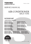
SERVICE MANUAL
AIR-CONDITIONER
SPLIT TYPE
OUTDOOR UNIT
<DIGITAL INVERTER>
RAV-SM2244AT8-E
RAV-SM2804AT8-E
RAV-SM2244AT8Z-E RAV-SM2804AT8Z-E
RAV-SM2244AT8ZG-E RAV-SM2804AT8ZG-E
RAV-SM2244AT7
RAV-SM2244AT7Z
RAV-SM2244AT7ZG
RAV-SM2804AT7
RAV-SM2804AT7Z
RAV-SM2804AT7ZG
R410A
PRINTED IN JAPAN, Jun, 2009 ToMo
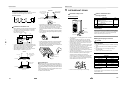
Adoption of New Refrigerant
This Air Conditioner is a new type which adopts a new refrigerant HFC (R410A) instead of the conventional
refrigerant R22 in order to prevent destruction of the ozone layer.
WARNING
Cleaning of the air filter and other parts of the air filter involves dangerous work in high places, so be sure to
have a service person do it. Do not attempt it yourself.
The cleaning diagram for the air filter is there for the service person, and not for the customer.
CONTENTS
SAFETY CAUTION ............................................................................................ 4
1. SPECIFICATIONS .................................................................................... 11
1-1. Indoor Unit......................................................................................................... 11
1-2. Outdoor Unit...................................................................................................... 24
1-3. Operation Characteristic Curve ....................................................................... 25
2. CONSTRUCTION VIEWS (EXTERNAL VIEWS)....................................... 27
2-1. Outdoor Unit...................................................................................................... 27
3. OUTDOOR UNIT REFRIGERANTING CYCLE DIAGRAM ...................... 31
4. WIRING DIAGRAM ................................................................................... 33
4-1. Outdoor Unit...................................................................................................... 33
5. SPECIFICATIONS OF ELECTRICAL PARTS .......................................... 34
5-1.Outdoor Unit ......................................................................................................... 34
6. REFRIGERANT R410A ............................................................................ 35
6-1.
6-2.
6-3.
6-4.
6-5.
6-6.
Safety During Installation/Servicing ............................................................... 35
Refrigerant Piping Installation ....................................................................... 35
Tools .................................................................................................................. 39
Recharging of Refrigerant................................................................................ 39
Brazing of Pipes................................................................................................ 40
Instructions for Re-use Piping of R22 or R407C ............................................ 42
–2–
7. CIRCUIT CONFIGURATION AND CONTROL SPECIFICATIONS ........... 45
7-1. Outdoor Unit Control ........................................................................................ 45
7-2. Outline of Main Controls .................................................................................. 49
8. TROUBLESHOOTING .............................................................................. 55
8-1. Summary of Troubleshooting ........................................................................... 55
8-2. Troubleshooting ................................................................................................ 57
9. SETUP AT LOCAL SITE AND OTHERS .................................................. 80
9-1. Calling of Error History .................................................................................... 80
9-2. Group Control Operation ................................................................................. 80
9-3. Outdoor Unit...................................................................................................... 82
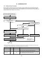
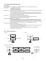
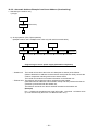
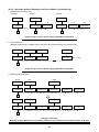
10. ADDRESS SETUP .................................................................................... 89
10-1.
10-2.
10-3.
10-4.
10-5.
Address Setup Procedure ................................................................................
Address Setup & Group Control ......................................................................
Remote Controller Wiring .................................................................................
Address Setup (Manual setting from remote controller) ...............................
Confirmation of Indoor Unit No. Position .......................................................
89
90
93
94
95
11. INSTALLATION MANUAL ........................................................................ 97
12. REPLACEMENT OF
THE SERVICE P.C. BOARD (4316V392) MCC-1599 ............................. 110
13. HOW TO EXCHANGE COMPRESSOR .................................................. 111
13-1. Exchanging Procedure of Compressor (Outline) ......................................... 111
13-2. Exchange of Compressor .............................................................................. 111
14. DETACHMENTS ..................................................................................... 112
14-1. Outdoor Unit.................................................................................................... 112
15. EXPLODED VIEWS AND PARTS LIST .................................................. 124
15-1.
15-2.
15-3.
15-4.
Outdoor Unit....................................................................................................
Inverter Assembly ...........................................................................................
Outdoor Unit....................................................................................................
Inverter Assembly ...........................................................................................
–3–
124
126
128
130
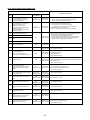
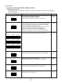
SAFETY CAUTION
The important contents concerned to the safety are described on the product itself and on this Service Manual.
Please read this Service Manual after understanding the described items thoroughly in the following contents
(Indications/Illustrated marks), and keep them.
[Explanation of indications]
Indication
Explanation
DANGER
Indicates contents assumed that an imminent danger causing a death or serious injury of
the repair engineers and the third parties when an incorrect work has been executed.
WARNING
Indicates possibilities assumed that a danger causing a death or serious injury of the
repair engineers, the third parties, and the users due to troubles of the product after work
when an incorrect work has been executed.
CAUTION
Indicates contents assumed that an injury or property damage (∗) may be caused on the
repair engineers, the third parties, and the users due to troubles of the product after work
when an incorrect work has been executed.
∗ Property damage : Enlarged damage concerned to property, furniture, and domestic animal/pet
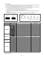
[Explanation of illustrated marks]
Mark
Explanation
Indicates prohibited items (Forbidden items to do)
The sentences near an illustrated mark describe the concrete prohibited contents.
Indicates mandatory items (Compulsory items to do)
The sentences near an illustrated mark describe the concrete mandatory contents.
Indicates cautions (Including danger/warning)
The sentences or illustration near or in an illustrated mark describe the concrete cautious contents.
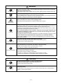
[Confirmation of warning label on the main unit]
Confirm that labels are indicated on the specified positions
(Refer to the Parts disassembly diagram (Outdoor unit).)
If removing the label during parts replace, stick it as the original.
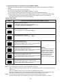
DANGER
Turn off breaker.
Execute discharge
between terminals.
Turn “OFF” the breaker before removing the front panel and cabinet, otherwise an electric
shock is caused by high voltage resulted in a death or injury.
During operation, a high voltage with 400V or higher of circuit (∗) at secondary circuit of the
high-voltage transformer is applied.
If touching a high voltage with the naked hands or body, an electric shock is caused even if using an
electric insulator.
• Attach a plate indicating “WORKING” or others on the breaker so that you don’t accidentally turn
on the breaker during work.
∗ : For details, refer to the electric wiring diagram.
When removing the front panel or cabinet, execute short-circuit and discharge between
high-voltage capacitor terminals.
If discharge is not executed, an electric shock is caused by high voltage resulted in a death or injury.
After turning off the breaker, high voltage also keeps to apply to the high-voltage capacitor.
Do not turn on the breaker under condition that the front panel and cabinet are removed.
An electric shock is caused by high voltage resulted in a death or injury.
Prohibition
–4–
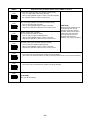
WARNING
Check earth wires.
Before troubleshooting or repair work, check the earth wire is connected to the earth
terminals of the main unit, otherwise an electric shock is caused when a leak occurs.
If the earth wire is not correctly connected, contact an electric engineer for rework.
Do not modify the products.
Do not also disassemble or modify the parts. It may cause a fire, electric shock or injury.
Prohibition of modification.
Use specified parts.
Do not bring a child
close to the equipment.
∗).
For spare parts, use those specified (∗
If unspecified parts are used, a fire or electric shock may be caused.
∗: For details, refer to the parts list.
Before troubleshooting or repair work, do not bring a third party (a child, etc.) except
the repair engineers close to the equipment.
It causes an injury with tools or disassembled parts.
Please inform the users so that the third party (a child, etc.) does not approach the equipment.
Connect the cut-off lead wires with crimp contact, etc, put the closed end side
upward and then apply a water-cut method, otherwise a leak or production of fire is
caused at the users’ side.
Insulating measures
No fire
When repairing the refrigerating cycle, take the following measures.
1) Be attentive to fire around the cycle. When using a gas stove, etc, be sure to put out fire
before work; otherwise the oil mixed with refrigerant gas may catch fire.
2) Do not use a welder in the closed room.
When using it without ventilation, carbon monoxide poisoning may be caused.
3) Do not bring inflammables close to the refrigerant cycle, otherwise fire of the welder may
catch the inflammables.
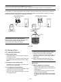
Check the used refrigerant name and use tools and materials of the parts which
match with it.
For the products which use R410A refrigerant, the refrigerant name is indicated at a
position on the outdoor unit where is easy to see. To prevent miss-charging, the route of the
service port is changed from one of the former R22.
For an air conditioner which uses R410A, never use other refrigerant than R410A.
For an air conditioner which uses other refrigerant (R22, etc.), never use R410A.
If different types of refrigerant are mixed, abnormal high pressure generates in the
refrigerating cycle and an injury due to breakage may be caused.
Refrigerant
Do not charge refrigerant additionally.
If charging refrigerant additionally when refrigerant gas leaks, the refrigerant composition in
the refrigerating cycle changes resulted in change of air conditioner characteristics or
refrigerant over the specified standard amount is charged and an abnormal high pressure is
applied to the inside of the refrigerating cycle resulted in cause of breakage or injury.
Therefore if the refrigerant gas leaks, recover the refrigerant in the air conditioner, execute
vacuuming, and then newly recharge the specified amount of liquid refrigerant.
In this time, never charge the refrigerant over the specified amount.
When recharging the refrigerant in the refrigerating cycle, do not mix the refrigerant
or air other than R410A into the specified refrigerant.
If air or others is mixed with the refrigerant, abnormal high pressure generates in the
refrigerating cycle resulted in cause of injury due to breakage.
After installation work, check the refrigerant gas does not leak.
If the refrigerant gas leaks in the room, poisonous gas generates when gas touches to fire
such as fan heater, stove or cocking stove though the refrigerant gas itself is innocuous.
Never recover the refrigerant into the outdoor unit.
When the equipment is moved or repaired, be sure to recover the refrigerant with
recovering device. The refrigerant cannot be recovered in the outdoor unit; otherwise a
serious accident such as breakage or injury is caused.
Assembly/Cabling
After repair work, surely assemble the disassembled parts, and connect and lead the
removed wires as before. Perform the work so that the cabinet or panel does not
catch the inner wires.
If incorrect assembly or incorrect wire connection was done, a disaster such as a leak or
fire is caused at user’s side.
–5–
WARNING
Insulator check
After the work has finished, be sure to use an insulation tester set (500V Megger) to
check the resistance is 2MΩ or more between the charge section and the non-charge
metal section (Earth position).
If the resistance value is low, a disaster such as a leak or electric shock is caused at user’s side.
Ventilation
When the refrigerant gas leaks during work, execute ventilation.
If the refrigerant gas touches to a fire, poisonous gas generates.
A case of leakage of the refrigerant and the closed room full with gas is dangerous because
a shortage of oxygen occurs. Be sure to execute ventilation.
When checking the circuit inevitably under condition of the power-ON, use rubber
gloves and others not to touch to the charging section.
If touching to the charging section, an electric shock may be caused.
Be attentive to
electric shock
When the refrigerant gas leaks, find up the leaked position and repair it surely.
If the leaked position cannot be found up and the repair work is interrupted, pump-down and
tighten the service valve, otherwise the refrigerant gas may leak into the room.
The poisonous gas generates when gas touches to fire such as fan heater, stove or cocking
stove though the refrigerant gas itself is innocuous.
Compulsion
When installing equipment which includes a large amount of charged refrigerant such
as a multi air conditioner in a sub-room, it is necessary that the density does not the
limit even if the refrigerant leaks.
If the refrigerant leaks and exceeds the limit density, an accident of shortage of oxygen is caused.
For the installation/moving/reinstallation work, follow to the Installation Manual.
If an incorrect installation is done, a trouble of the refrigerating cycle, water leak, electric
shock or fire is caused.
After repair work has finished, check there is no trouble.
If check is not executed, a fire, electric shock or injury may be caused.
For a check, turn off the power breaker.
Check after repair
After repair work (installation of front panel and cabinet) has finished, execute a test
run to check there is no generation of smoke or abnormal sound.
If check is not executed, a fire or an electric shock is caused.
Before test run, install the front panel and cabinet.
Check after reinstallation
Check the following items after reinstallation.
1) The earth wire is correctly connected.
2) The power cord is not caught in the product.
3) There is no inclination or unsteadiness and the installation is stable.
If check is not executed, a fire, an electric shock or an injury is caused.
CAUTION
Put on gloves
Cooling check
Be sure to put on the gloves (∗) and a long sleeved shirt:
otherwise an injury may be caused with the parts, etc.
(∗) Heavy gloves such as work gloves
When the power was turned on, start to work after the equipment has been
sufficiently cooled.
As temperature of the compressor pipes and others became high due to cooling/heating
operation, a burn may be caused.
–6–
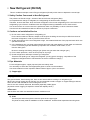
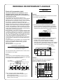
• New Refrigerant (R410A)
This air conditioner adopts a new HFC type refrigerant (R410A) which does not deplete the ozone layer.
1. Safety Caution Concerned to New Refrigerant
The pressure of R410A is high 1.6 times of that of the former refrigerant (R22).
Accompanied with change of refrigerant, the refrigerating oil has been also changed.
Therefore, be sure that water, dust, the former refrigerant or the former refrigerating oil is not mixed into the
refrigerating cycle of the air conditioner with new refrigerant during installation work or service work.
If an incorrect work or incorrect service is performed, there is a possibility to cause a serious accident.
Use the tools and materials exclusive to R410A to purpose a safe work.
2. Cautions on Installation/Service
1) Do not mix the other refrigerant or refrigerating oil.
For the tools exclusive to R410A, shapes of all the joints including the service port differ from those of
the former refrigerant in order to prevent mixture of them.
2) As the use pressure of the new refrigerant is high, use material thickness of the pipe and tools which are
specified for R410A.
3) In the installation time, use clean pipe materials and work with great attention so that water and others do
not mix in because pipes are affected by impurities such as water, oxide scales, oil, etc.
Use the clean pipes.
Be sure to brazing with flowing nitrogen gas. (Never use gas other than nitrogen gas.)
4) For the earth protection, use a vacuum pump for air purge.
5) R410A refrigerant is azeotropic mixture type refrigerant.
Therefore use liquid type to charge the refrigerant. (If using gas for charging, composition of the
refrigerant changes and then characteristics of the air conditioner change.)
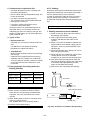
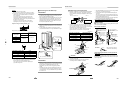
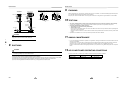
3. Pipe Materials
For the refrigerant pipes, copper pipe and joints are mainly used.
It is necessary to select the most appropriate pipes to conform to the standard.
Use clean material in which impurities adhere inside of pipe or joint to a minimum.
1) Copper pipe
<Piping>
The pipe thickness, flare finishing size, flare nut and others differ according to a refrigerant type.
When using a long copper pipe for R410A, it is recommended to select “Copper or copper-base pipe without
seam” and one with bonded oil amount 40mg/10m or less.
Also do not use crushed, deformed, discolored (especially inside) pipes.
(Impurities cause clogging of expansion valves and capillary tubes.)
<Flare nut>
Use the flare nuts which are attached to the air conditioner unit.
2) Joint
The flare joint and socket joint are used for joints of the copper pipe.
The joints are rarely used for installation of the air conditioner. However clear impurities when using them.
–7–
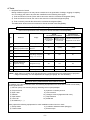
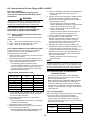
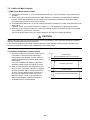
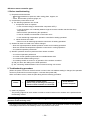
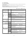
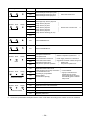
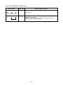
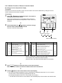
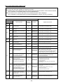
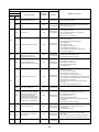
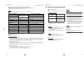
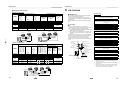
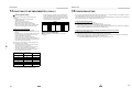
4. Tools
1. Required Tools for R410A
Mixing of different types of oil may cause a trouble such as generation of sludge, clogging of capillary,
etc. Accordingly, the tools to be used are classified into the following three types.
1) Tools exclusive for R410A (Those which cannot be used for conventional refrigerant (R22))
2) Tools exclusive for R410A, but can be also used for conventional refrigerant (R22)
3) Tools commonly used for R410A and for conventional refrigerant (R22)
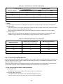
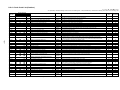
The table below shows the tools exclusive for R410A and their interchangeability.
Tools exclusive for R410A (The following tools for R410A are required.)
Tools whose specifications are changed for R410A and their interchangeability
R410A
air conditioner installation
No.
Used tool
Usage
Conventional air
conditioner installation
Existence of
new equipment
for R410A
Whether conventional equipment
can be used
Whether conventional
equipment can be used
Q
Flare tool
Pipe flaring
Yes
∗ (Note)
Yes
R
Copper pipe gauge for
adjusting projection margin
Flaring by conventional
flare tool
Yes
∗ (Note)
∗ (Note)
S
Torque wrench
Tightening of flare nut
Yes
No
No
T
Gauge manifold
U
Yes
No
No
Charge hose
Evacuating, refrigerant
charge, run check, etc.
V
Vacuum pump adapter
Vacuum evacuating
Yes
No
Yes
W
Electronic balance for
refrigerant charging
Refrigerant charge
Yes
Yes
Yes
X
Refrigerant cylinder
Refrigerant charge
Yes
No
No
Y
Leakage detector
Gas leakage check
Yes
No
Yes
(Note) When flaring is carried out for R410A using the conventional flare tools, adjustment of projection
margin is necessary. For this adjustment, a copper pipe gauge, etc. are necessary.
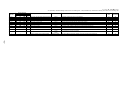
General tools (Conventional tools can be used.)
In addition to the above exclusive tools, the following equipments which serve also for R22 are necessary
as the general tools.
1) Vacuum pump. Use vacuum pump by attaching vacuum pump adapter.
2) Torque wrench
8) Spanner or Monkey wrench
3) Pipe cutter
9) Hole core drill
4) Reamer
10) Hexagon wrench (Opposite side 4mm)
5) Pipe bender
11) Tape measure
6) Level vial
12) Metal saw
7) Screwdriver (+, –)
Also prepare the following equipments for other installation method and run check.
1) Clamp meter
3) Insulation resistance tester (Megger)
2) Thermometer
4) Electroscope
–8–
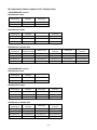
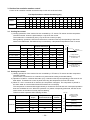
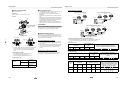
n Combination Pattern (Indoor Unit / Outdoor Unit)
<RAV-SM2244AT series>
Simultaneous twin
4-way air discharge
cassette type
Concealed
duct type
Ceiling type
RAV-SM1104UT-E
RAV-SM1102BT-E
RAV-SM1102CT-E
RAV-SM1104UT-E
RAV-SM1102BT-E
RAV-SM1102CT-E
Simultaneous triple
4-way air discharge
cassette type
Concealed
duct type
Ceiling type
High wall type
(2 series)
RAV-SM804UT-E
RAV-SM802BT-E
RAV-SM802CT-E
RAV-SM802KRT-E
RAV-SM804UT-E
RAV-SM802BT-E
RAV-SM802CT-E
RAV-SM802KRT-E
RAV-SM804UT-E
RAV-SM802BT-E
RAV-SM802CT-E
RAV-SM802KRT-E
Simultaneous double twin
4-way air discharge
cassette type
Compact 4-way
cassette (600×600) type
Slim duct type
Concealed
duct type
Ceiling type
High wall type
(2 series)
RAV-SM564UT-E
RAV-SM562MUT-E
RAV-SM564SDT-E
RAV-SM562BT-E
RAV-SM562CT-E
RAV-SM562KRT-E
RAV-SM564UT-E
RAV-SM562MUT-E
RAV-SM564SDT-E
RAV-SM562BT-E
RAV-SM562CT-E
RAV-SM562KRT-E
RAV-SM564UT-E
RAV-SM562MUT-E
RAV-SM564SDT-E
RAV-SM562BT-E
RAV-SM562CT-E
RAV-SM562KRT-E
RAV-SM564UT-E
RAV-SM562MUT-E
RAV-SM564SDT-E
RAV-SM562BT-E
RAV-SM562CT-E
RAV-SM562KRT-E
<RAV-SM2804AT series>
Simultaneous twin
4-way air discharge
cassette type
Concealed
duct type
Ceiling type
RAV-SM1404UT-E
RAV-SM1402BT-E
RAV-SM1402CT-E
RAV-SM1404UT-E
RAV-SM1402BT-E
RAV-SM1402CT-E
Simultaneous triple
4-way air discharge
cassette type
Concealed
duct type
Ceiling type
High wall type
(2 series)
RAV-SM804UT-E
RAV-SM802BT-E
RAV-SM802CT-E
RAV-SM802KRT-E
RAV-SM804UT-E
RAV-SM802BT-E
RAV-SM802CT-E
RAV-SM802KRT-E
RAV-SM804UT-E
RAV-SM802BT-E
RAV-SM802CT-E
RAV-SM802KRT-E
Simultaneous double twin
4-way air discharge
cassette type
Concealed
duct type
Ceiling type
High wall type
(2 series)
RAV-SM804UT-E
RAV-SM802BT-E
RAV-SM802CT-E
RAV-SM802KRT-E
RAV-SM804UT-E
RAV-SM802BT-E
RAV-SM802CT-E
RAV-SM802KRT-E
RAV-SM804UT-E
RAV-SM802BT-E
RAV-SM802CT-E
RAV-SM802KRT-E
RAV-SM804UT-E
RAV-SM802BT-E
RAV-SM802CT-E
RAV-SM802KRT-E
–9–
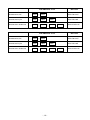
RAV-SM2244AT series
Slimultaneous twin
SM110
—
SM110
Simultaneous triple
SM80
—
SM80
—
SM80
Simultaneous double twin
SM56
—
SM56
—
SM56
Branch kit
RBC-TWP101E
RBC-TRP100E
—
SM56
RAV-SM2804AT series
Slimultaneous twin
SM140
—
SM140
Simultaneous triple
SM80
—
SM80
—
SM80
Simultaneous double twin
SM80
—
SM80
—
SM80
RBC-DTWP101E
Branch kit
RBC-TWP101E
– 10 –
RBC-TRP100E
—
SM80
RBC-DTWP101E
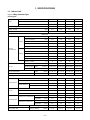
1. SPECIFICATIONS
1-1. Indoor Unit
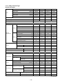
1-1-1. 4-Way Cassette Type
<Twin type>
Model
Indoor unit 1
RAV-SM
1104UT-E
1404UT-E
1104UT-E
1404UT-E
Indoor unit 2
RAV-SM
1104UT-E
1404UT-E
1104UT-E
1404UT-E
Outdoor unit
RAV-SM
2244AT8-E
2804AT8-E
2244AT7
2804AT7
Cooling capacity
(kW)
20.0
23.0
20.0
23.0
Heating capacity
(kW)
22.4
27.0
22.4
27.0
Power supply
3 phase 380 – 415V 50Hz
3 phase 380V 60Hz
Indoor unit
Running current
(A)
Power consumption
Cooling
Power factor
10.09 – 9.24
13.24 – 12.12
10.09
13.24
(kW)
6.24
8.19
6.24
8.19
(%)
94
94
94
94
3.21
2.81
3.21
2.81
A
C
—
—
9.41 – 8.61
12.09 – 11.07
9.41
12.09
(kW)
5.82
7.48
5.82
7.48
(%)
94
94
94
94
3.85
3.61
3.85
3.61
A
A
—
—
18
22
18
22
Turbo fan
Turbo fan
Turbo fan
Turbo fan
EER
Energy efficiency class ∗
Electrical
characteristics
Running current
(A)
Power consumption
Heating
Power factor
COP
Energy efficiency class ∗
Maximum current
(A)
Fan
Fan unit
Standard air flow
H/M/L
Motor
(m³/min.)
(W)
33.5/24.0/19.5 35.0/24.0/20.5 33.5/24.0/19.5 35.0/24.0/20.5
68
72
68
72
Sound pressure level
H/M/L
(dB•A)
43 / 38 / 33
44 / 38 / 34
43 / 38 / 33
44 / 38 / 34
Sound power level
H/M/L
(dB•A)
58 / 53 / 48
59 / 53 / 49
58 / 53 / 48
59 / 53 / 49
Outdoor unit
Max. total length
(m)
70
70
70
70
Min. length
(m)
7.5
7.5
7.5
7.5
Outdoor lower
(m)
30
30
30
30
Outdoor high
(m)
30
30
30
30
Propeller fan
Propeller fan
Propeller fan
Propeller fan
133
133
133
133
100 + 100
100 + 100
100 + 100
100 + 100
Outer dimension
Height difference
Fan
Fan unit
Standard air flow high
(m³/min.)
Motor
(W)
Gas side
(mm)
28.6
28.6
28.6
28.6
Liquid side
(mm)
12.7
12.7
12.7
12.7
Gas side
(mm)
15.9
15.9
15.9
15.9
Liquid side
(mm)
9.5
9.5
9.5
9.5
Outdoor unit – Pipe branch
Connecting pipe
Pipe branch – Indoor unit
Sound pressure level
Cooling / Heating
(dB•A)
56 / 57
57 / 58
56 / 57
57 / 58
Sound power level
Cooling / Heating
(dB•A)
72 / 74
74 / 75
72 / 74
74 / 75
∗ : IEC standard
– 11 –
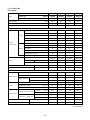
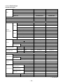
1-1-2. Duct Type
<Twin type>
Model
Indoor unit 1
RAV-SM
1102BT-E
1402BT-E
1102BT-E
14002BT-E
Indoor unit 2
RAV-SM
1102BT-E
1402BT-E
1102BT-E
1402BT-E
Outdoor unit
RAV-SM
2244AT8-E
2804AT8-E
2244AT7
2804AT7
Cooling capacity
(kW)
20.0
23.0
20.0
23.0
Heating capacity
(kW)
22.4
27.0
22.4
27.0
Power supply
3 phase 380 – 415V 50Hz
3 phase 380V 60Hz
Indoor unit
Running current
(A)
Power consumption
Cooling
Power factor
9.55
7.12
9.55
(%)
94
94
94
94
2.81
2.41
2.81
2.41
C
E
—
—
10.34 – 9.47
12.80 – 11.72
10.34
12.80
(kW)
6.40
7.92
6.40
7.92
(%)
94
94
94
94
3.50
3.41
3.50
3.41
B
B
—
—
18
22
18
22
Centrifugal
Centrifugal
Centrifugal
Centrifugal
(A)
Power consumption
Heating
Power factor
COP
Energy efficiency class ∗
Maximum current
(A)
Fan
Fan unit
Standard air flow
H/M/L
Motor
15.44
7.12
Energy efficiency class ∗
Running current
11.51
(kW)
EER
Electrical
characteristics
11.51 – 10.54 15.44 – 14.13
(m³/min.)
(W)
27.0/23.0/18.9 33.0/28.0/23.1 27.0/23.0/18.9 33.0/28.0/23.1
120
120
120
120
Sound pressure level
H/M/L
(dB•A)
42 / 39 / 36
44 / 41 / 38
42 / 39 / 36
44 / 41 / 38
Sound power level
H/M/L
(dB•A)
57 / 54 / 51
59 / 56 / 53
57 / 54 / 51
59 / 56 / 53
Outdoor unit
Max. total length
(m)
70
70
70
70
Min. length
(m)
7.5
7.5
7.5
7.5
Outdoor lower
(m)
30
30
30
30
Outdoor high
(m)
30
30
30
30
Propeller fan
Propeller fan
Propeller fan
Propeller fan
133
133
133
133
100 + 100
100 + 100
100 + 100
100 + 100
Outer dimension
Height difference
Fan
Fan unit
Standard air flow high
(m³/min.)
Motor
(W)
Gas side
(mm)
28.6
28.6
28.6
28.6
Liquid side
(mm)
12.7
12.7
12.7
12.7
Gas side
(mm)
15.9
15.9
15.9
15.9
Liquid side
(mm)
9.5
9.5
9.5
9.5
Outdoor unit – Pipe branch
Connecting pipe
Pipe branch – Indoor unit
Sound pressure level
Cooling / Heating
(dB•A)
56 / 57
57 / 58
56 / 57
57 / 58
Sound power level
Cooling / Heating
(dB•A)
72 / 74
74 / 75
72 / 74
74 / 75
∗ : IEC standard
– 12 –
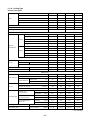
1-1-3. Ceiling Type
<Twin type>
Model
Indoor unit 1
RAV-SM
1102CT-E
1402CT-E
1102CT-E
1402CT-E
Indoor unit 2
RAV-SM
1102CT-E
1402CT-E
1102CT-E
1402CT-E
Outdoor unit
RAV-SM
2244AT8-E
2804AT8-E
2244AT7
2804AT7
Cooling capacity
(kW)
20.0
23.0
20.0
23.0
Heating capacity
(kW)
22.4
27.0
22.4
27.0
Power supply
3 phase 380 – 415V 50Hz
3 phase 380V 60Hz
Indoor unit
Running current
(A)
Power consumption
Cooling
Power factor
9.55
7.12
9.55
(%)
94
94
94
94
2.81
2.41
2.81
2.41
C
E
—
—
10.34 – 9.47
12.80 – 11.72
10.34
12.80
(kW)
6.40
7.92
6.40
7.92
(%)
94
94
94
94
3.50
3.41
3.50
3.41
B
B
—
—
18
22
18
22
Centrifugal
Centrifugal
Centrifugal
Centrifugal
(A)
Power consumption
Heating
Power factor
COP
Energy efficiency class ∗
Maximum current
(A)
Fan
Fan unit
Standard air flow
H/M/L
Motor
15.44
7.12
Energy efficiency class ∗
Running current
11.51
(kW)
EER
Electrical
characteristics
11.51 – 10.54 15.44 – 14.13
(m³/min.)
(W)
27.5/24.0/21.2 30.0/26.0/23.1 27.5/24.0/21.2 30.0/26.0/23.1
120
120
120
120
Sound pressure level
H/M/L
(dB•A)
41 / 38 / 35
43 / 40 / 37
41 / 38 / 35
43 / 40 / 37
Sound power level
H/M/L
(dB•A)
56 / 53 / 50
58 / 55 / 52
56 / 53 / 50
58 / 55 / 52
Outdoor unit
Max. total length
(m)
70
70
70
70
Min. length
(m)
7.5
7.5
7.5
7.5
Outdoor lower
(m)
30
30
30
30
Outdoor high
(m)
30
30
30
30
Propeller fan
Propeller fan
Propeller fan
Propeller fan
133
133
133
133
100 + 100
100 + 100
100 + 100
100 + 100
Outer dimension
Height difference
Fan
Fan unit
Standard air flow high
(m³/min.)
Motor
(W)
Gas side
(mm)
28.6
28.6
28.6
28.6
Liquid side
(mm)
12.7
12.7
12.7
12.7
Gas side
(mm)
15.9
15.9
15.9
15.9
Liquid side
(mm)
9.5
9.5
9.5
9.5
Outdoor unit – Pipe branch
Connecting pipe
Pipe branch – Indoor unit
Sound pressure level
Cooling / Heating
(dB•A)
56 / 57
57 / 58
56 / 57
57 / 58
Sound power level
Cooling / Heating
(dB•A)
72 / 74
74 / 75
72 / 74
74 / 75
∗ : IEC standard
– 13 –
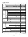
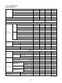
1-1-4. 4-Way Cassette Type
<Triple type>
Indoor unit 1
RAV-SM
804UT-E
804UT-E
804UT-E
804UT-E
Indoor unit 2
RAV-SM
804UT-E
804UT-E
804UT-E
804UT-E
Indoor unit 3
RAV-SM
804UT-E
804UT-E
804UT-E
804UT-E
Outdoor unit
RAV-SM
2244AT8-E
2804AT8-E
2244AT7
2804AT7
Model
Cooling capacity
(kW)
20.0
23.0
20.0
23.0
Heating capacity
(kW)
22.4
27.0
22.4
27.0
Power supply
3 phase 380 – 415V 50Hz
3 phase 380V 60Hz
Indoor unit
Running current
(A)
Power consumption
Cooling
Power factor
9.55
7.12
9.55
(%)
94
94
94
94
2.81
2.41
2.81
2.41
C
E
—
—
10.34 – 9.47
12.80 – 11.72
10.34
12.80
(kW)
6.40
7.92
6.40
7.92
(%)
94
94
94
94
3.50
3.41
3.50
3.41
B
B
—
—
18
22
18
22
Turbo fan
Turbo fan
Turbo fan
Turbo fan
(A)
Power consumption
Heating
Power factor
COP
Energy efficiency class ∗
Maximum current
(A)
Fan
Fan unit
Standard air flow
H/M/L
Motor
15.44
7.12
Energy efficiency class ∗
Running current
11.51
(kW)
EER
Electrical
characteristics
11.51 – 10.54 15.44 – 14.13
(m³/min.)
(W)
20.5/16.0/13.5 20.5/16.0/13.5 20.5/16.0/13.5 20.5/16.0/13.5
20
20
20
20
Sound pressure level
H/M/L
(dB•A)
35 / 31 / 28
35 / 31 / 28
35 / 31 / 28
35 / 31 / 28
Sound power level
H/M/L
(dB•A)
50 / 46 / 43
50 / 46 / 43
50 / 46 / 43
50 / 46 / 43
Outdoor unit
Max. total length
(m)
70
70
70
70
Min. length
(m)
7.5
7.5
7.5
7.5
Outdoor lower
(m)
30
30
30
30
Outdoor high
(m)
30
30
30
30
Propeller fan
Propeller fan
Propeller fan
Propeller fan
133
133
133
133
100 + 100
100 + 100
100 + 100
100 + 100
Outer dimension
Height difference
Fan
Fan unit
Standard air flow high
(m³/min.)
Motor
(W)
Gas side
(mm)
28.6
28.6
28.6
28.6
Liquid side
(mm)
12.7
12.7
12.7
12.7
Gas side
(mm)
15.9
15.9
15.9
15.9
Liquid side
(mm)
9.5
9.5
9.5
9.5
Outdoor unit – Pipe branch
Connecting pipe
Pipe branch – Indoor unit
Sound pressure level
Cooling / Heating
(dB•A)
56 / 57
57 / 58
56 / 57
57 / 58
Sound power level
Cooling / Heating
(dB•A)
72 / 74
74 / 75
72 / 74
74 / 75
∗ : IEC standard
– 14 –
1-1-5. Duct Type
<Triple type>
Indoor unit 1
RAV-SM
802BT-E
802BT-E
802BT-E
802BT-E
Indoor unit 2
RAV-SM
802BT-E
802BT-E
802BT-E
802BT-E
Indoor unit 3
RAV-SM
802BT-E
802BT-E
802BT-E
802BT-E
Outdoor unit
RAV-SM
2244AT8-E
2804AT8-E
2244AT7
2804AT7
Model
Cooling capacity
(kW)
20.0
23.0
20.0
23.0
Heating capacity
(kW)
22.4
27.0
22.4
27.0
Power supply
3 phase 380 – 415V 50Hz
3 phase 380V 60Hz
Indoor unit
Running current
(A)
Power consumption
Cooling
Power factor
9.55
7.12
9.55
(%)
94
94
94
94
2.81
2.41
2.81
2.41
C
E
—
—
10.34 – 9.47
12.80 – 11.72
10.34
12.80
(kW)
6.40
7.92
6.40
7.92
(%)
94
94
94
94
3.50
3.41
3.50
3.41
B
B
—
—
18
22
18
22
Centrifugal
Centrifugal
Centrifugal
Centrifugal
(A)
Power consumption
Heating
Power factor
COP
Energy efficiency class ∗
Maximum current
(A)
Fan
Fan unit
Standard air flow
H/M/L
Motor
15.44
7.12
Energy efficiency class ∗
Running current
11.51
(kW)
EER
Electrical
characteristics
11.51 – 10.54 15.44 – 14.13
(m³/min.)
(W)
19.0/16.2/13.3 19.0/16.2/13.3 19.0/16.2/13.3 19.0/16.2/13.3
120
120
120
120
Sound pressure level
H/M/L
(dB•A)
40 / 37 / 34
40 / 37 / 34
40 / 37 / 34
40 / 37 / 34
Sound power level
H/M/L
(dB•A)
55 / 52 / 49
55 / 52 / 49
55 / 52 / 49
55 / 52 / 49
Outdoor unit
Max. total length
(m)
70
70
70
70
Min. length
(m)
7.5
7.5
7.5
7.5
Outdoor lower
(m)
30
30
30
30
Outdoor high
(m)
30
30
30
30
Propeller fan
Propeller fan
Propeller fan
Propeller fan
133
133
133
133
100 + 100
100 + 100
100 + 100
100 + 100
Outer dimension
Height difference
Fan
Fan unit
Standard air flow high
(m³/min.)
Motor
(W)
Gas side
(mm)
28.6
28.6
28.6
28.6
Liquid side
(mm)
12.7
12.7
12.7
12.7
Gas side
(mm)
15.9
15.9
15.9
15.9
Liquid side
(mm)
9.5
9.5
9.5
9.5
Outdoor unit – Pipe branch
Connecting pipe
Pipe branch – Indoor unit
Sound pressure level
Cooling / Heating
(dB•A)
56 / 57
57 / 58
56 / 57
57 / 58
Sound power level
Cooling / Heating
(dB•A)
72 / 74
74 / 75
72 / 74
74 / 75
∗ : IEC standard
– 15 –
1-1-6. Ceiling Type
<Triple type>
Indoor unit 1
RAV-SM
802CT-E
802CT-E
802CT-E
802CT-E
Indoor unit 2
RAV-SM
802CT-E
802CT-E
802CT-E
802CT-E
Indoor unit 3
RAV-SM
802CT-E
802CT-E
802CT-E
802CT-E
Outdoor unit
RAV-SM
2244AT8-E
2804AT8-E
2244AT7
2804AT7
Model
Cooling capacity
(kW)
20.0
23.0
20.0
23.0
Heating capacity
(kW)
22.4
27.0
22.4
27.0
Power supply
3 phase 380 – 415V 50Hz
3 phase 380V 60Hz
Indoor unit
Running current
(A)
Power consumption
Cooling
Power factor
9.55
7.12
9.55
(%)
94
94
94
94
2.81
2.41
2.81
2.41
C
E
—
—
10.34 – 9.47
12.80 – 11.72
10.34
12.80
(kW)
6.40
7.92
6.40
7.92
(%)
94
94
94
94
3.50
3.41
3.50
3.41
B
B
—
—
18
22
18
22
Centrifugal
Centrifugal
Centrifugal
Centrifugal
(A)
Power consumption
Heating
Power factor
COP
Energy efficiency class ∗
Maximum current
(A)
Fan
Fan unit
Standard air flow
H/M/L
Motor
15.44
7.12
Energy efficiency class ∗
Running current
11.51
(kW)
EER
Electrical
characteristics
11.51 – 10.54 15.44 – 14.13
(m³/min.)
(W)
18.5/16.7/14.6 18.5/16.7/14.6 18.5/16.7/14.6 18.5/16.7/14.6
60
60
60
60
Sound pressure level
H/M/L
(dB•A)
38 / 36 / 33
38 / 36 / 33
38 / 36 / 33
38 / 36 / 33
Sound power level
H/M/L
(dB•A)
53 / 51 / 48
53 / 51 / 48
53 / 51 / 48
53 / 51 / 48
Outdoor unit
Max. total length
(m)
70
70
70
70
Min. length
(m)
7.5
7.5
7.5
7.5
Outdoor lower
(m)
30
30
30
30
Outdoor high
(m)
30
30
30
30
Propeller fan
Propeller fan
Propeller fan
Propeller fan
133
133
133
133
100 + 100
100 + 100
100 + 100
100 + 100
Outer dimension
Height difference
Fan
Fan unit
Standard air flow high
(m³/min.)
Motor
(W)
Gas side
(mm)
28.6
28.6
28.6
28.6
Liquid side
(mm)
12.7
12.7
12.7
12.7
Gas side
(mm)
15.9
15.9
15.9
15.9
Liquid side
(mm)
9.5
9.5
9.5
9.5
Outdoor unit – Pipe branch
Connecting pipe
Pipe branch – Indoor unit
Sound pressure level
Cooling / Heating
(dB•A)
56 / 57
57 / 58
56 / 57
57 / 58
Sound power level
Cooling / Heating
(dB•A)
72 / 74
74 / 75
72 / 74
74 / 75
∗ : IEC standard
– 16 –
1-1-7. High Wall Type
<Triple type>
Indoor unit 1
RAV-SM
802KRT-E
802KRT-E
802KRT-E
802KRT-E
Indoor unit 2
RAV-SM
802KRT-E
802KRT-E
802KRT-E
802KRT-E
Indoor unit 3
RAV-SM
802KRT-E
802KRT-E
802KRT-E
802KRT-E
Outdoor unit
RAV-SM
2244AT8-E
2804AT8-E
2244AT7
2804AT7
Model
Cooling capacity
(kW)
20.0
23.0
20.0
23.0
Heating capacity
(kW)
22.4
27.0
22.4
27.0
Power supply
3 phase 380 – 415V 50Hz
3 phase 380V 60Hz
Indoor unit
Running current
(A)
Power consumption
Cooling
Power factor
9.55
7.12
9.55
(%)
94
94
94
94
2.81
2.41
2.81
2.41
C
E
—
—
10.34 – 9.47
12.80 – 11.72
10.34
12.80
(kW)
6.40
7.92
6.40
7.92
(%)
94
94
94
94
3.50
3.41
3.50
3.41
B
B
—
—
18
22
18
22
(A)
Power consumption
Heating
Power factor
COP
Energy efficiency class ∗
Maximum current
(A)
Fan
Fan unit
15.44
7.12
Energy efficiency class ∗
Running current
11.51
(kW)
EER
Electrical
characteristics
11.51 – 10.54 15.44 – 14.13
Cross flow fan Cross flow fan Cross flow fan Cross flow fan
Standard air flow
H/M/L
Motor
(m³/min.)
(W)
18.5/14.6/12.2 18.5/14.6/12.2 18.5/14.6/12.2 18.5/14.6/12.2
30
30
30
30
Sound pressure level
H/M/L
(dB•A)
45 / 41 / 36
45 / 41 / 36
45 / 41 / 36
45 / 41 / 36
Sound power level
H/M/L
(dB•A)
60 / 56 / 51
60 / 56 / 51
60 / 56 / 51
60 / 56 / 51
Outdoor unit
Max. total length
(m)
70
70
70
70
Min. length
(m)
7.5
7.5
7.5
7.5
Outdoor lower
(m)
30
30
30
30
Outdoor high
(m)
30
30
30
30
Propeller fan
Propeller fan
Propeller fan
Propeller fan
133
133
133
133
100 + 100
100 + 100
100 + 100
100 + 100
Outer dimension
Height difference
Fan
Fan unit
Standard air flow high
(m³/min.)
Motor
(W)
Gas side
(mm)
28.6
28.6
28.6
28.6
Liquid side
(mm)
12.7
12.7
12.7
12.7
Gas side
(mm)
15.9
15.9
15.9
15.9
Liquid side
(mm)
9.5
9.5
9.5
9.5
Outdoor unit – Pipe branch
Connecting pipe
Pipe branch – Indoor unit
Sound pressure level
Cooling / Heating
(dB•A)
56 / 57
57 / 58
56 / 57
57 / 58
Sound power level
Cooling / Heating
(dB•A)
72 / 74
74 / 75
72 / 74
74 / 75
∗ : IEC standard
– 17 –
1-1-8. 4-Way Cassette Type
<Double twin type>
Model
Indoor unit 1
RAV-SM
564UT-E
804UT-E
564UT-E
804UT-E
Indoor unit 2
RAV-SM
564UT-E
804UT-E
564UT-E
804UT-E
Indoor unit 3
RAV-SM
564UT-E
804UT-E
564UT-E
804UT-E
Indoor unit 4
RAV-SM
564UT-E
804UT-E
564UT-E
804UT-E
Outdoor unit
RAV-SM
2244AT8-E
2804AT8-E
2244AT7
2804AT7
Cooling capacity
(kW)
20.0
23.0
20.0
23.0
Heating capacity
(kW)
22.4
27.0
22.4
27.0
Power supply
3 phase 380 – 415V 50Hz
3 phase 380V 60Hz
Indoor unit
Running current
(A)
Power consumption
Cooling
Power factor
9.55
7.12
9.55
(%)
94
94
94
94
2.81
2.41
2.81
2.41
C
E
—
—
10.34 – 9.47
12.80 – 11.72
10.34
12.80
(kW)
6.40
7.92
6.40
7.92
(%)
94
94
94
94
3.50
3.41
3.50
3.41
B
B
—
—
18
22
18
22
Turbo fan
Turbo fan
Turbo fan
Turbo fan
(A)
Power consumption
Heating
Power factor
COP
Energy efficiency class ∗
Maximum current
(A)
Fan
Fan unit
Standard air flow
H/M/L
Motor
15.44
7.12
Energy efficiency class ∗
Running current
11.51
(kW)
EER
Electrical
characteristics
11.51 – 10.54 15.44 – 14.13
(m³/min.)
(W)
17.5/14.5/13.0 20.5/16.0/13.5 17.5/14.5/13.0 20.5/16.0/13.5
14
20
14
20
Sound pressure level
H/M/L
(dB•A)
32 / 29 / 28
35 / 31 / 28
32 / 29 / 28
35 / 31 / 28
Sound power level
H/M/L
(dB•A)
47 / 44 / 43
50 / 46 / 43
47 / 44 / 43
50 / 46 / 43
Outdoor unit
Max. total length
(m)
70
70
70
70
Min. length
(m)
7.5
7.5
7.5
7.5
Outdoor lower
(m)
30
30
30
30
Outdoor high
(m)
30
30
30
30
Propeller fan
Propeller fan
Propeller fan
Propeller fan
133
133
133
133
100 + 100
100 + 100
100 + 100
100 + 100
Outer dimension
Height difference
Fan
Fan unit
Standard air flow high
(m³/min.)
Motor
(W)
Gas side
(mm)
28.6
28.6
28.6
28.6
Liquid side
(mm)
12.7
12.7
12.7
12.7
Gas side
(mm)
15.9
15.9
15.9
15.9
Liquid side
(mm)
9.5
9.5
9.5
9.5
Outdoor unit – Pipe branch
Connecting pipe
Pipe branch – Indoor unit
Sound pressure level
Cooling / Heating
(dB•A)
56 / 57
57 / 58
56 / 57
57 / 58
Sound power level
Cooling / Heating
(dB•A)
72 / 74
74 / 75
72 / 74
74 / 75
∗ : IEC standard
– 18 –
1-1-9. Compact 4-Way Cassette (600 × 600) Type
<Double twin type>
Model
Indoor unit 1
RAV-SM562MUT-E
RAV-SM562MUT-E
Indoor unit 2
RAV-SM562MUT-E
RAV-SM562MUT-E
Indoor unit 3
RAV-SM562MUT-E
RAV-SM562MUT-E
Indoor unit 4
RAV-SM562MUT-E
RAV-SM562MUT-E
Outdoor unit
RAV-SM2244AT8-E
RAV-SM2244AT7
Cooling capacity
(kW)
20.0
20.0
Heating capacity
(kW)
22.4
22.4
3 phase 380 – 415V 50Hz
3 phase 380V 60Hz
11.51 – 10.54
11.51
(kW)
7.12
7.12
(%)
94
94
2.81
2.81
C
—
10.34 – 9.47
10.34
(kW)
6.40
6.40
(%)
94
94
3.50
3.50
B
—
18
18
Turbo fan
Turbo fan
13.3 / 11.2 / 9.1
13.3 / 11.2 / 9.1
60
60
Power supply
Indoor unit
Running current
(A)
Power consumption
Cooling
Power factor
EER
Energy efficiency class ∗
Electrical
characteristics
Running current
(A)
Power consumption
Heating
Power factor
COP
Energy efficiency class ∗
Maximum current
(A)
Fan
Fan unit
Standard air flow
H/M/L
Motor
(m³/min.)
(W)
Sound pressure level
H/M/L
(dB•A)
43 / 39 / 34
43 / 39 / 34
Sound power level
H/M/L
(dB•A)
58 / 54 / 49
58 / 54 / 49
Outdoor unit
Max. total length
(m)
70
70
Min. length
(m)
7.5
7.5
Outdoor lower
(m)
30
30
Outdoor high
(m)
30
30
Propeller fan
Propeller fan
133
133
100 + 100
100 + 100
Outer dimension
Height difference
Fan
Fan unit
Standard air flow high
(m³/min.)
Motor
Connecting pipe
(W)
Outdoor unit –
First pipe branch
Gas side
(mm)
28.6
28.6
Liquid side
(mm)
12.7
12.7
First pipe branch –
Second pipe branch
Gas side
(mm)
15.9
15.9
Liquid side
(mm)
9.5
9.5
Second pipe branch –
Indoor unit
Gas side
(mm)
12.7
12.7
Liquid side
(mm)
6.4
6.4
Sound pressure level
Cooling / Heating
(dB•A)
56 / 57
56 / 57
Sound power level
Cooling / Heating
(dB•A)
72 / 74
72 / 74
∗ : IEC standard
– 19 –
1-1-10. Slim Duct Type
<Double twin type>
Model
Indoor unit 1
RAV-SM564SDT-E
RAV-SM564SDT-E
Indoor unit 2
RAV-SM564SDT-E
RAV-SM564SDT-E
Indoor unit 3
RAV-SM564SDT-E
RAV-SM564SDT-E
Indoor unit 4
RAV-SM564SDT-E
RAV-SM564SDT-E
Outdoor unit
RAV-SM2244AT8-E
RAV-SM2244AT7
Cooling capacity
(kW)
20.0
20.0
Heating capacity
(kW)
22.4
22.4
3 phase 380 – 415V 50Hz
3 phase 380V 60Hz
Power supply
Indoor unit
Running current
(A)
Power consumption
Cooling
Power factor
11.51 – 10.54
11.51
(kW)
7.12
7.12
(%)
94
94
2.81
2.81
EER
Energy efficiency class ∗
Electrical
characteristics
Running current
(A)
Power consumption
Heating
(kW)
Power factor
(%)
COP
Energy efficiency class ∗
Maximum current
(A)
Fan
Standard air flow
Fan unit
H/M/L
Extermal
static pressure
Sound pressure level
Sound power level
Standard (at shipment)
Set up for tap exchange
—
10.34
6.40
6.40
94
94
3.50
3.50
B
—
18
18
Centrifugal fan
Centrifugal fan
13.0 / 11.3 / 9.7
13.0 / 11.3 / 9.7
(W)
60
60
(Pa)
10
10
(Pa)
(m³/min.)
Motor
C
10.34 – 9.47
10 / 20 / 35 / 50
10 / 20 / 35 / 50
Under air inlet
H/M/L
(dB•A)
45 / 40 / 36
45 / 40 / 36
Back air inlet
H/M/L
(dB•A)
33 / 31 / 28
33 / 31 / 28
Under air inlet
H/M/L
(dB•A)
60 / 55 / 51
60 / 55 / 51
Back air inlet
H/M/L
(dB•A)
48 / 46 / 43
48 / 46 / 43
Outdoor unit
Outer dimension
Max. total length
(m)
70
70
Min. length
(m)
7.5
7.5
Height difference
Outdoor lower
(m)
30
30
Outdoor high
(m)
30
30
Propeller fan
Propeller fan
Fan
Fan unit
Standard air flow high
(m³/min.)
Motor
Connecting pipe
133
133
100 + 100
100 + 100
(mm)
28.6
28.6
Liquid side
(mm)
12.7 12.7
(W)
Outdoor unit –
First pipe branch
Gas side
First pipe branch –
Second pipe branch
Gas side
(mm)
15.9
15.9
Liquid side
(mm)
9.5
9.5
Second pipe branch –
Indoor unit
Gas side
(mm)
12.7
12.7
Liquid side
(mm)
6.4
6.4
Sound pressure level
Cooling / Heating
(dB•A)
56 / 57
56 / 57
Sound power level
Cooling / Heating
(dB•A)
72 / 74
72 / 74
∗ : IEC standard
– 20 –
1-1-11. Duct Type
<Double twin type>
Model
Indoor unit 1
RAV-SM
562BT-E
802BT-E
562BT-E
802BT-E
Indoor unit 2
RAV-SM
562BT-E
802BT-E
562BT-E
802BT-E
Indoor unit 3
RAV-SM
562BT-E
802BT-E
562BT-E
802BT-E
Indoor unit 4
RAV-SM
562BT-E
802BT-E
562BT-E
802BT-E
Outdoor unit
RAV-SM
2244AT8-E
2804AT8-E
2244AT7
2804AT7
Cooling capacity
(kW)
20.0
23.0
20.0
23.0
Heating capacity
(kW)
22.4
27.0
22.4
27.0
Power supply
3 phase 380 – 415V 50Hz
3 phase 380V 60Hz
Indoor unit
Running current
(A)
Power consumption
Cooling
Power factor
9.55
7.12
9.55
(%)
94
94
94
94
2.81
2.41
2.81
2.41
C
E
—
—
10.34 – 9.47
12.80 – 11.72
10.34
12.80
(kW)
6.40
7.92
6.40
7.92
(%)
94
94
94
94
3.50
3.41
3.50
3.41
B
B
—
—
18
22
18
22
Centrifugal
Centrifugal
Centrifugal
Centrifugal
(A)
Power consumption
Heating
Power factor
COP
Energy efficiency class ∗
Maximum current
(A)
Fan
Fan unit
Standard air flow
H/M/L
(m³/min.)
Motor
15.44
7.12
Energy efficiency class ∗
Running current
11.51
(kW)
EER
Electrical
characteristics
11.51 – 10.54 15.44 – 14.13
(W)
13.0/11.9/9.8 19.0/16.2/13.3 13.0/11.9/9.8 19.0/16.2/13.3
120
120
120
120
Sound pressure level
H/M/L
(dB•A)
40 / 37 / 33
40 / 37 / 34
40 / 37 / 33
40 / 37 / 34
Sound power level
H/M/L
(dB•A)
55 / 52 / 48
55 / 52 / 49
55 / 52 / 48
55 / 52 / 49
Outdoor unit
Max. total length
(m)
70
70
70
70
Min. length
(m)
7.5
7.5
7.5
7.5
Outdoor lower
(m)
30
30
30
30
Outdoor high
(m)
30
30
30
30
Propeller fan
Propeller fan
Propeller fan
Propeller fan
133
133
133
133
100 + 100
100 + 100
100 + 100
100 + 100
Outer dimension
Height difference
Fan
Fan unit
Standard air flow high
(m³/min.)
Motor
Connecting pipe
(W)
Outdoor unit –
First pipe branch
Gas side
(mm)
28.6
28.6
28.6
28.6
Liquid side
(mm)
12.7
12.7
12.7
12.7
First pipe branch –
Second pipe branch
Gas side
(mm)
15.9
15.9
15.9
15.9
Liquid side
(mm)
9.5
9.5
9.5
9.5
Second pipe branch –
Indoor unit
Gas side
(mm)
12.7
15.9
12.7
15.9
Liquid side
(mm)
6.4
9.5
6.4
9.5
Sound pressure level
Cooling / Heating
(dB•A)
56 / 57
57 / 58
56 / 57
57 / 58
Sound power level
Cooling / Heating
(dB•A)
72 / 74
74 / 75
72 / 74
74 / 75
∗ : IEC standard
– 21 –
1-1-12. Ceiling Type
<Double twin type>
Model
Indoor unit 1
RAV-SM
562CT-E
802CT-E
562CT-E
802CT-E
Indoor unit 2
RAV-SM
562CT-E
802CT-E
562CT-E
802CT-E
Indoor unit 3
RAV-SM
562CT-E
802CT-E
562CT-E
802CT-E
Indoor unit 4
RAV-SM
562CT-E
802CT-E
562CT-E
802CT-E
Outdoor unit
RAV-SM
2244AT8-E
2804AT8-E
2244AT7
2804AT7
Cooling capacity
(kW)
20.0
23.0
20.0
23.0
Heating capacity
(kW)
22.4
27.0
22.4
27.0
Power supply
3 phase 380 – 415V 50Hz
3 phase 380V 60Hz
Indoor unit
Running current
(A)
Power consumption
Cooling
Power factor
9.55
7.12
9.55
(%)
94
94
94
94
2.81
2.41
2.81
2.41
C
E
—
—
10.34 – 9.47
12.80 – 11.72
10.34
12.80
(kW)
6.40
7.92
6.40
7.92
(%)
94
94
94
94
3.50
3.41
3.50
3.41
B
B
—
—
18
22
18
22
Centrifugal
Centrifugal
Centrifugal
Centrifugal
(A)
Power consumption
Heating
Power factor
COP
Energy efficiency class ∗
Maximum current
(A)
Fan
Fan unit
Standard air flow
H/M/L
(m³/min.)
Motor
15.44
7.12
Energy efficiency class ∗
Running current
11.51
(kW)
EER
Electrical
characteristics
11.51 – 10.54 15.44 – 14.13
(W)
13.0/11.2/10.0 18.5/16.7/14.6 13.0/11.2/10.0 18.5/16.7/14.6
60
60
60
60
Sound pressure level
H/M/L
(dB•A)
36 / 33 / 30
38 / 36 / 33
36 / 33 / 30
38 / 36 / 33
Sound power level
H/M/L
(dB•A)
51 / 48 / 45
53 / 51 / 48
51 / 48 / 45
53 / 51 / 48
Outdoor unit
Max. total length
(m)
70
70
70
70
Min. length
(m)
7.5
7.5
7.5
7.5
Outdoor lower
(m)
30
30
30
30
Outdoor high
(m)
30
30
30
30
Propeller fan
Propeller fan
Propeller fan
Propeller fan
133
133
133
133
100 + 100
100 + 100
100 + 100
100 + 100
Outer dimension
Height difference
Fan
Fan unit
Standard air flow high
(m³/min.)
Motor
Connecting pipe
(W)
Outdoor unit –
First pipe branch
Gas side
(mm)
28.6
28.6
28.6
28.6
Liquid side
(mm)
12.7
12.7
12.7
12.7
First pipe branch –
Second pipe branch
Gas side
(mm)
15.9
15.9
15.9
15.9
Liquid side
(mm)
9.5
9.5
9.5
9.5
Second pipe branch –
Indoor unit
Gas side
(mm)
12.7
15.9
12.7
15.9
Liquid side
(mm)
6.4
9.5
6.4
9.5
Sound pressure level
Cooling / Heating
(dB•A)
56 / 57
57 / 58
56 / 57
57 / 58
Sound power level
Cooling / Heating
(dB•A)
72 / 74
74 / 75
72 / 74
74 / 75
∗ : IEC standard
– 22 –
1-1-12. High Wall Type
<Double twin type>
Model
Indoor unit 1
RAV-SM
562KRT-E
802KRT-E
562KRT-E
802KRT-E
Indoor unit 2
RAV-SM
562KRT-E
802KRT-E
562KRT-E
802KRT-E
Indoor unit 3
RAV-SM
562KRT-E
802KRT-E
562KRT-E
802KRT-E
Indoor unit 4
RAV-SM
562KRT-E
802KRT-E
562KRT-E
802KRT-E
Outdoor unit
RAV-SM
2244AT8-E
2804AT8-E
2244AT7
2804AT7
Cooling capacity
(kW)
20.0
23.0
20.0
23.0
Heating capacity
(kW)
22.4
27.0
22.4
27.0
Power supply
3 phase 380 – 415V 50Hz
3 phase 380V 60Hz
Indoor unit
Running current
(A)
Power consumption
Cooling
Power factor
9.55
7.12
9.55
(%)
94
94
94
94
2.81
2.41
2.81
2.41
C
E
—
—
10.34 – 9.47
12.80 – 11.72
10.34
12.80
(kW)
6.40
7.92
6.40
7.92
(%)
94
94
94
94
3.50
3.41
3.50
3.41
B
B
—
—
18
22
18
22
(A)
Power consumption
Heating
Power factor
COP
Energy efficiency class ∗
Maximum current
(A)
Fan
Fan unit
Standard air flow
15.44
7.12
Energy efficiency class ∗
Running current
11.51
(kW)
EER
Electrical
characteristics
11.51 – 10.54 15.44 – 14.13
Cross flow fan Cross flow fan Cross flow fan Cross flow fan
H/M/L
(m³/min.)
Motor
(W)
14.0/12.5/10.7 18.5/14.6/12.2 14.0/12.5/10.7 18.5/14.6/12.2
30
30
30
30
Sound pressure level
H/M/L
(dB•A)
39 / 36 / 33
45 / 41 / 36
39 / 36 / 33
45 / 41 / 36
Sound power level
H/M/L
(dB•A)
54 / 51 / 48
60 / 56 / 51
54 / 51 / 48
60 / 56 / 51
Outdoor unit
Max. total length
(m)
70
70
70
70
Min. length
(m)
7.5
7.5
7.5
7.5
Outdoor lower
(m)
30
30
30
30
Outdoor high
(m)
30
30
30
30
Propeller fan
Propeller fan
Propeller fan
Propeller fan
133
133
133
133
100 + 100
100 + 100
100 + 100
100 + 100
Outer dimension
Height difference
Fan
Fan unit
Standard air flow high
(m³/min.)
Motor
Connecting pipe
(W)
Outdoor unit –
First pipe branch
Gas side
(mm)
28.6
28.6
28.6
28.6
Liquid side
(mm)
12.7
12.7
12.7
12.7
First pipe branch –
Second pipe branch
Gas side
(mm)
15.9
15.9
15.9
15.9
Liquid side
(mm)
9.5
9.5
9.5
9.5
Second pipe branch –
Indoor unit
Gas side
(mm)
12.7
12.7
12.7
12.7
Liquid side
(mm)
6.4
9.5
6.4
9.5
Sound pressure level
Cooling / Heating
(dB•A)
56 / 57
57 / 58
56 / 57
57 / 58
Sound power level
Cooling / Heating
(dB•A)
72 / 74
74 / 75
72 / 74
74 / 75
∗ : IEC standard
– 23 –
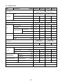
1-2. Outdoor Unit
Model
Outdoor unit
RAV-SM
2804AT8-E
2244AT7
2804AT7
1 phase 380 – 415V 50Hz
1 phase 380V 60Hz
(Power exclusive to outdoor is required.)
Power supply
Type
Compressor
2244AT8-E
Hermetic compressor
Motor
(kW)
Pole
Refrigerant charged
(kg)
Refrigerant control
Hermetic compressor
3.75
3.75
3.75
3.75
4
4
4
4
5.9
5.9
5.9
5.9
Pulse motor valve
Pulse motor valve
Max. total length
(m)
70
70
70
70
Min. length
(m)
7.5
7.5
7.5
7.5
Outdoor lower
(m)
30
30
30
30
Outdoor higher
(m)
30
30
30
30
Pipe
Height difference
Outer dimension
Height
(mm)
1540
1540
1540
1540
Width
(mm)
900
900
900
900
Depth
(mm)
320
320
320
320
Appearance
Total weight
(kg)
Heat exchanger
Fan
Fan unit
Standard air flow
Motor
Connecting pipe
(Outdoor unit side)
(m³/min.)
(W)
Silky shade
(Muncel 1Y8.5/0.5)
Silky shade
(Muncel 1Y8.5/0.5)
134
134
134
134
Finned tube
Finned tube
Propeller fan
Propeller fan
133
133
133
133
100 + 100
100 + 100
100 + 100
100 + 100
Gas side
(mm)
19.1
19.1
19.1
19.1
Liquid side
(mm)
12.7
12.7
12.7
12.7
Sound pressure level
Cooling/Heating
(dB•A)
56 / 57
57 / 58
56 / 57
57 / 58
Sound power level
Cooling/Heating
(dB•A)
72 / 74
74 / 75
72 / 74
74 / 75
Outside air temperature, Cooling
(°C)
46 to –15°C
46 to –15°C
Outside air temperature, Heating
(°C)
15 to –20°C
15 to –20°C
– 24 –
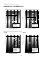
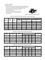
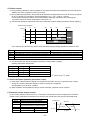
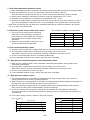
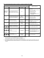
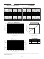
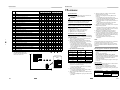
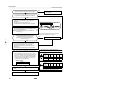
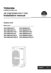
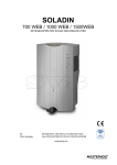
1-3. Operation Characteristic Curve
• Operation characteristic curve <Digital Inverter>
RAV-SM2244AT8 (Z) (ZG) -E, RAV-SM2804AT8 (Z) (ZG) -E
<Cooling>
<Heating>
18
18
16
16
14
14
SM280
SM280
12
Current (A)
Current (A)
12
10
8
SM224
6
4
0
0
20
40
60
SM224
8
6
4
• Conditions
Indoor : DB27˚C/WB19˚C
Outdoor : DB35˚C
Air flow : High
Pipe length : 7.5m
400V, 50Hz (3 phase)
2
10
80
• Conditions
Indoor : DB20˚C
Outdoor : DB7˚C/WB6˚C
Air flow : High
Pipe length : 7.5m
400V, 50Hz (3 phase)
2
0
100
0
20
Compressor speed (rps)
40
60
80
100
Compressor speed (rps)
RAV-SM2244AT7 (Z) (ZG), RAV-SM2804AT7 (Z) (ZG)
<Cooling>
<Heating>
18
18
16
16
SM280
14
14
12
Current (A)
Current (A)
12
10
8
SM224
6
4
0
20
40
60
80
10
SM224
8
6
4
• Conditions
Indoor : DB27˚C/WB19˚C
Outdoor : DB35˚C
Air flow : High
Pipe length : 7.5m
380V, 60Hz (3 phase)
2
0
SM280
• Conditions
Indoor : DB20˚C
Outdoor : DB7˚C/WB6˚C
Air flow : High
Pipe length : 7.5m
380V, 60Hz (3 phase)
2
100
Compressor speed (rps)
0
0
20
40
60
Compressor speed (rps)
– 25 –
80
100
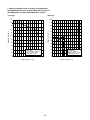
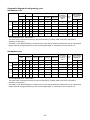
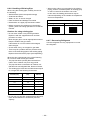
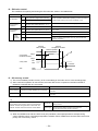
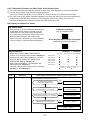
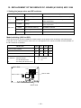
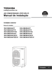
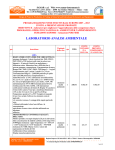
• Capacity variation ratio according to temperature
RAV-SM2244AT8 (Z) (ZG) -E, RAV-SM2804AT8 (Z) (ZG) -E
RAV-SM2244AT7 (Z) (ZG), RAV-SM2804AT7 (Z) (ZG)
<Cooling>
<Heating>
105
120
100
110
95
100
90
Capacity ratio (%)
Capacity ratio (%)
90
85
80
75
70
65
60
55
80
70
60
50
40
30
20
• Conditions
Indoor : DB27˚C/WB19˚C
Indoor air flow : High
Pipe length : 7.5m
10
50
32 33 34 35 36 37 38 39 40 41 42 43 44 45 46
Outdoor temp. (˚C)
• Conditions
Indoor : DB20˚C
Indoor air flow : High
Pipe length : 7.5m
0
-20 -18 -16 -14 -12 -10 -8 -6 -4 -2 0
Outdoor temp. (˚C)
– 26 –
2
4
6
8 10
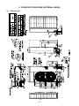
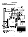
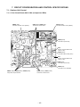
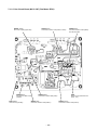
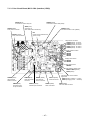
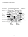
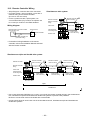
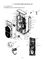
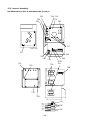
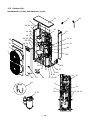
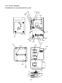
2. CONSTRUCTION VIEWS (EXTERNAL VIEWS)
2-1. Outdoor Unit
– 27 –
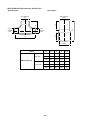
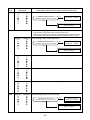
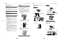
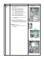
RBC-DTWP101E (Simultaneous Double Twin)
<Branch pipe>
<Joint pipe>
Outer diameter
Ø25.4
B
24
Inner diameter
ØC
54
Inner
diameter
ØD
22
Inner
diameter
ØD
A
Inner diameter
Ø28.6
1 pc.
Model
Gas side
A
B
C
D
Q’ty
74
37
25.4
15.9
1
42
23
15.9
15.9
2
43
23
15.9
12.7
2
35
18
12.7
9.5
1
34
14
9.5
9.5
2
36
14
9.5
6.4
2
RBC-DTWP101E
Liquid side
– 28 –
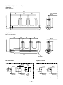
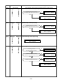
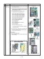
RBC-TRP100E (Simultaneous Triple)
<Gas side>
Header assembly
300
80
Inner diameter
Ø15.9
80
100
Inner diameter Ø25.4
100
1 pc.
<Liquid side>
Branch pipe assembly
35
80
80
Inner diameter
Ø9.52
100
Inner diameter Ø12.7
100
1 pc.
Insulator
Gas side socket
Liquid side socket
Ø15.9
Outer diameter
Ø25.4
Ø12.7
(External
diameter)
(External
diameter)
1 pc.
Inner
diameter
Ø28.6
1 pc.
Ø9.5
Ø12.7
(External
diameter)
(External
diameter)
3 pcs.
– 29 –
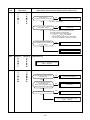
9
6
26
22
Ø25.4
24
54
24
12
46
28
10
Ø15.9
3 pcs.
Ø9.5
Ø6.4
1 pc.
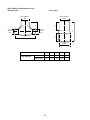
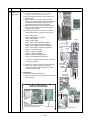
RBC-TWP101E (Simultaneous Twin)
<Branch pipe>
<Joint pipe>
Outer diameter
Ø25.4
B
24
Inner diameter
ØC
54
Inner
diameter
ØD
22
Inner
diameter
ØD
A
Inner diameter
Ø28.6
1 pc.
Model
A
B
C
D
Q’ty
Gas side
74
37
25.4
15.9
1
Liquid side
35
18
12.7
9.5
1
RBC-TWP101E
– 30 –
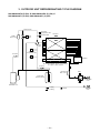
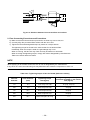
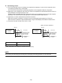
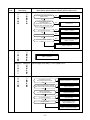
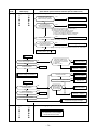
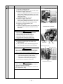
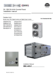
3. OUTDOOR UNIT REFRIGERANTING CYCLE DIAGRAM
RAV-SM2244AT8 (Z) (ZG) -E, RAV-SM2804AT8 (Z) (ZG) -E
RAV-SM2244AT7 (Z) (ZG), RAV-SM2804AT7 (Z) (ZG)
Solenoid valve
Check joint
High-pressure side
TO sensor
Muffler
Ø45 × 230 L
P Pressure switch
Check
valve
TL sensor
4-way
valve
Check joint
Low-pressure side
TD sensor
TE sensor
P
Pressure
sensor
Distributor
Heat exchanger
Ø8, 2 rows, 60 stages + Ø9.5, 1 row, 60 stages
13-13 pass + under cool pass
TS sensor
Liquid tank
Ø45 × 420 L
PMV 1
Accumulator
(8500cc) Ø161.6
Packed valve
Ø12.7
PMV 2
Compressor
DA550A3F-11M
: Cooling
: Heating
– 31 –
: Strainer
Ball valve
Ø19.1
Systematic diagram of refrigerating cycle
RAV-SM2244 series
Pressure
(MPa)
Cooling
Heating
Pipe surface temperature (°C)
(kg/cm²g)
Discharge
Suction
Indoor heat
exchanger
Compressor
Outdoor heat drive revolution
frequency
exchanger
(rps)
(TE)
∗
Pd
Ps
Pd
Ps
(TD)
(TS)
(TC)
Standard
3.14
0.88
32.0
9.0
84
14
10
37
64
Overload
3.54
1.14
36.1
11.6
88
17
16
46
Low load
1.65
0.65
16.8
6.6
41
7
5
Standard
2.60
0.67
26.5
6.8
73
2
Overload
3.24
1.08
33.1
11.0
77
Low load
2.05
0.31
20.9
3.2
76
Indoor
fan
Indoor/Outdoor
temp. conditions
(DB/WB) (°C)
Indoor
Outdoor
HIGH
27/19
35/–
62
HIGH
32/24
43/–
0
36
LOW
18/15.5
–15/–
42
2
66
HIGH
20/–
7/6
14
52
13
36
LOW
30/–
24/18
–12
34
–11
75
HIGH
15/–
–10/(70%)
∗ This compressor has a 4-pole motor.
The value when compressor frequency (Hz) is measured by a clamp meter is twice the compressor
revolution number (rps).
∗ This data is cycle data obtained by combining a four-way ceiling cassette simultaneous twin at a target pipe
length. Data will change depending on the mounted pipe length or combination with the indoor unit.
RAV-SM2804 series
Pressure
(MPa)
Cooling
Heating
Pipe surface temperature (°C)
(kg/cm²g)
Discharge
Suction
Indoor heat
exchanger
Compressor
Outdoor heat drive revolution
frequency
exchanger
(rps)
(TE)
∗
Pd
Ps
Pd
Ps
(TD)
(TS)
(TC)
Standard
3.15
0.79
32.1
8.1
87
11
9
41
80
Overload
3.62
1.12
36.9
11.4
89
18
16
48
Low load
1.66
0.64
16.9
6.5
42
6
5
Standard
2.85
0.63
29.1
6.4
80
1
Overload
3.26
1.06
33.3
10.8
78
Low load
2.05
0.29
20.9
3.0
81
Indoor
fan
Indoor/Outdoor
temp. conditions
(DB/WB) (°C)
Indoor
Outdoor
HIGH
27/19
35/–
64
HIGH
32/24
43/–
0
36
LOW
18/15.5
–15/–
47
2
80
HIGH
20/–
7/6
14
53
12
36
LOW
30/–
24/18
–13
33
–12
96
HIGH
15/–
–10/(70%)
∗ This compressor has a 4-pole motor.
The value when compressor frequency (Hz) is measured by a clamp meter is twice the compressor
revolution number (rps).
∗ This data is cycle data obtained by combining a four-way ceiling cassette simultaneous twin at a target pipe
length. Data will change depending on the mounted pipe length or combination with the indoor unit.
– 32 –
4. WIRING DIAGRAM
4-1. Outdoor Unit
RAV-SM2244AT8 (Z) (ZG) -E, RAV-SM2804AT8 (Z) (ZG) -E
RAV-SM2244AT7 (Z) (ZG), RAV-SM2804AT7 (Z) (ZG)
Compressor
IPDU board
MCC-1596
Noise Filter
P.C. board
MCC-1600
Fan IPDU board
MCC-1597
Interface (CDB)
P.C. board
MCC-1599
– 33 –
MCC-1436
5. SPECIFICATIONS OF ELECTRICAL PARTS
5-1. Outdoor Unit
RAV-SM2244AT8 (Z) (ZG) -E, RAV-SM2804AT8 (Z) (ZG) -E
RAV-SM2244AT7 (Z) (ZG), RAV-SM2804AT7 (Z) (ZG)
No.
Parts name
Type
Specifications
—
1
Compressor
DA550A3F-11M
2
Outdoor fan motor
ICF-280-A100-1
DC 280 V, 100 W
3
4-way valve coil
STF-01AJ502E1
AC 220 – 240 V, 50 Hz
4
4-way valve coil (for AT7)
VHV-01AH553A1
AC 220 V, 60 Hz
5
2-way valve coil
VPV-MOAJ524C0
AC 220 – 240 V, 50 Hz
6
2-way valve coil (for AT7)
VPV-MOAH551B1
AC 220 V, 60 Hz
7
PMV coil
8
High pressure switch
9
Reactor
CH-44
1.4 mH, 25 A
10
Reactor
CH-68
18 mH, 5 A
11
Reactor
CH-56
5.8 mH, 18.5 A
12
P.C. board (Compressor drive)
MCC-1596
—
13
P.C. board (Fan motor drive)
MCC-1597
—
14
P.C. board (Control)
MCC-1599
—
15
P.C. board (Noise filter)
MCC-1600
—
16
P.C. board (Fan extention)
MCC-1436
—
17
Outdoor temp. sensor (TO sensor)
—
10 kΩ at 25°C
18
Discharge temp. sensor (TD sensor)
—
50 kΩ at 25°C
19
Suction temp. sensor (TS sensor)
—
10 kΩ at 25°C
20
Heat exchanger sensor (TE sensor)
—
10 kΩ at 25°C
21
Heat exchanger mid. temp. sensor (TL sensor)
—
10 kΩ at 25°C
22
Fuse
23
Fuse (Mounted on P.C. board, MCC-1596)
GAC1 31.5A
24
Fuse (Mounted on P.C. board, MCC-1596)
SCT 31.5A
25
Fuse (Mounted on P.C. board, MCC-1597)
GDM 250V 15A
26
Fuse (Mounted on P.C. board, MCC-1597)
SCT 31.5A
T3.15 A, AC 250 V
27
Fuse (Mounted on P.C. board, MCC-1599)
FJL 250V 31.5A
T3.15 A, AC 250 V
28
Fuse (Mounted on P.C. board, MCC-1600)
ET 6.3A
T6.3 A, AC 250 V
29
Relay
30
Posistor
31
Compressor thermo.
UKV-25D22
ACB-4UB83W
TLC 25A
EL200/240A2-F(M)
ZPR0YCE 101A 500
US-622
– 34 –
DC 12 V
OFF : 4.15 MPa
25 A, 250 V
31.5 A, 500 V
T3.15 A, AC 250 V
15 A, 250 V
Contact : AC 480 V, 20A
100 Ω, 500 V
OFF : 125 ± 4 °C, ON : 60 ± 5 °C
6. REFRIGERANT R410A
This air conditioner adopts the new refrigerant HFC
(R410A) which does not damage the ozone layer.
The working pressure of the new refrigerant R410A
is 1.6 times higher than conventional refrigerant
(R22). The refrigerating oil is also changed in
accordance with change of refrigerant, so be careful
that water, dust, and existing refrigerant or
refrigerating oil are not entered in the refrigerant
cycle of the air conditioner using the new refrigerant
during installation work or servicing time.
The next section describes the precautions for air
conditioner using the new refrigerant.
Conforming to contents of the next section together
with the general cautions included in this manual,
perform the correct and safe work.
6-1. Safety During Installation/Servicing
As R410A’s pressure is about 1.6 times higher than
that of R22, improper installation/servicing may
cause a serious trouble. By using tools and
materials exclusive for R410A, it is necessary to
carry out installation/servicing safely while taking
the following precautions into consideration.
1. Never use refrigerant other than R410A in an air
conditioner which is designed to operate with
R410A.
If other refrigerant than R410A is mixed,
pressure in the refrigeration cycle becomes
abnormally high, and it may cause personal
injury, etc. by a rupture.
2. Confirm the used refrigerant name, and use
tools and materials exclusive for the refrigerant
R410A.
The refrigerant name R410A is indicated on the
visible place of the outdoor unit of the air
conditioner using R410A as refrigerant.
To prevent mischarging, the diameter of the
service port differs from that of R22.
3. If a refrigeration gas leakage occurs during
installation/servicing, be sure to ventilate fully.
If the refrigerant gas comes into contact with fire,
a poisonous gas may occur.
4. When installing or removing an air conditioner,
do not allow air or moisture to remain in the
refrigeration cycle.
Otherwise, pressure in the refrigeration cycle
may become abnormally high so that a rupture
or personal injury may be caused.
5. After completion of installation work, check to
make sure that there is no refrigeration gas
leakage.
If the refrigerant gas leaks into the room, coming
into contact with fire in the fan-driven heater,
space heater, etc., a poisonous gas may occur.
6. When an air conditioning system charged with a
large volume of refrigerant is installed in a small
room, it is necessary to exercise care so that,
even when refrigerant leaks, its concentration
does not exceed the marginal level.
If the refrigerant gas leakage occurs and its
concentration exceeds the marginal level, an
oxygen starvation accident may result.
7. Be sure to carry out installation or removal
according to the installation manual.
Improper installation may cause refrigeration
trouble, water leakage, electric shock, fire, etc.
8. Unauthorized modifications to the air conditioner
may be dangerous. If a breakdown occurs
please call a qualified air conditioner technician
or electrician.
Improper repair may result in water leakage,
electric shock and fire, etc.
6-2. Refrigerant Piping Installation
6-2-1. Piping Materials and Joints Used
For the refrigerant piping installation, copper pipes
and joints are mainly used.
Copper pipes and joints suitable for the refrigerant
must be chosen and installed.
Furthermore, it is necessary to use clean copper
pipes and joints whose interior surfaces are less
affected by contaminants.
1. Copper Pipes
It is necessary to use seamless copper pipes
which are made of either copper or copper alloy
and it is desirable that the amount of residual oil
is less than 40 mg/10 m.
Do not use copper pipes having a collapsed,
deformed or discolored portion (especially on
the interior surface).
Otherwise, the expansion valve or capillary tube
may become blocked with contaminants.
As an air conditioner using R410A incurs pressure higher than when using R22, it is necessary
to choose adequate materials.
Thicknesses of copper pipes used with R410A
are as shown in Table 6-2-1. Never use copper
pipes thinner than 0.8mm even when it is available on the market.
NOTE
Refer to the “6-6. Instructions for Re-use Piping
of R22 or R407C”.
– 35 –
Table 6-2-1 Thicknesses of annealed copper pipes
Thickness (mm)
Nominal diameter
Outer diameter (mm)
R410A
R22
1/4
6.4
0.80
0.80
3/8
9.5
0.80
0.80
1/2
12.7
0.80
0.80
5/8
15.9
1.00
1.00
1. Joints
For copper pipes, flare joints or socket joints are used. Prior to use, be sure to remove all contaminants.
a) Flare Joints
Flare joints used to connect the copper pipes cannot be used for pipings whose outer diameter exceeds
20 mm. In such a case, socket joints can be used.
Sizes of flare pipe ends, flare joint ends and flare nuts are as shown in Tables 6-2-3 to 6-2-5 below.
b) Socket Joints
Socket joints are such that they are brazed for connections, and used mainly for thick pipings whose
diameter is larger than 20 mm. Thicknesses of socket joints are as shown in Table 6-2-2.
Table 6-2-2 Minimum thicknesses of socket joints
Nominal diameter
Reference outer diameter of
copper pipe jointed (mm)
Minimum joint thickness
(mm)
1/4
6.4
0.50
3/8
9.5
0.60
1/2
12.7
0.70
5/8
15.9
0.80
6-2-2. Processing of Piping Materials
When performing the refrigerant piping installation, care should be taken to ensure that water or dust does not
enter the pipe interior, that no other oil other than lubricating oils used in the installed air conditioner is used,
and that refrigerant does not leak.
When using lubricating oils in the piping processing, use such lubricating oils whose water content has been
removed. When stored, be sure to seal the container with an airtight cap or any other cover.
1. Flare Processing Procedures and Precautions
a) Cutting the Pipe
By means of a pipe cutter, slowly cut the pipe so that it is not deformed.
b) Removing Burrs and Chips
If the flared section has chips or burrs, refrigerant leakage may occur.
Carefully remove all burrs and clean the cut surface before installation.
– 36 –
c) Insertion of Flare Nut
d) Flare Processing
Make certain that a clamp bar and copper pipe have been cleaned.
By means of the clamp bar, perform the flare processing correctly.
Use either a flare tool for R410A or conventional flare tool.
Flare processing dimensions differ according
to the type of flare tool.
When using a conventional flare tool, be sure
to secure “dimension A” by using a gauge for
size adjustment.
ØD
A
Fig. 6-2-1 Flare processing dimensions
Table 6-2-3 Dimensions related to flare processing for R410A / R22
A (mm)
Nominal
diameter
Outer
diameter
(mm)
Thickness
(mm)
Flare tool for
R410A, R22
clutch type
Conventional flare tool
(R410A)
Conventional flare tool
(R22)
Clutch type
Wing nut type
Clutch type
Wing nut type
1/4
6.4
0.8
0 to 0.5
1.0 to 1.5
1.5 to 2.0
0.5 to 1.0
1.0 to 1.5
3/8
9.5
0.8
0 to 0.5
1.0 to 1.5
1.5 to 2.0
0.5 to 1.0
1.0 to 1.5
1/2
12.7
0.8
0 to 0.5
1.0 to 1.5
2.0 to 2.5
0.5 to 1.0
1.5 to 2.0
5/8
15.9
1.0
0 to 0.5
1.0 to 1.5
2.0 to 2.5
0.5 to 1.0
1.5 to 2.0
3/4
19.1
1.2
0 to 0.5
1.0 to 1.5
2.0 to 2.5
—
—
Table 6-2-4 Flare and flare nut dimensions for R410A
Nominal
diameter
Outer diameter
(mm)
Thickness
(mm)
1/4
6.4
3/8
Dimension (mm)
Flare nut width
(mm)
A
B
C
D
0.8
9.1
9.2
6.5
13
17
9.5
0.8
13.2
13.5
9.7
20
22
1/2
12.7
0.8
16.6
16.0
12.9
23
26
5/8
15.9
1.0
19.7
19.0
16.0
25
29
3/4
19.1
1.2
24.0
—
19.2
28
36
Table 6-2-5 Flare and flare nut dimensions for R22
Nominal
diameter
Outer diameter
(mm)
Thickness
(mm)
1/4
6.4
3/8
Dimension (mm)
Flare nut width
(mm)
A
B
C
D
0.8
9.1
9.2
6.5
13
17
9.5
0.8
13.0
13.5
9.7
20
22
1/2
12.7
0.8
16.2
16.0
12.9
20
24
5/8
15.9
1.0
19.4
19.0
16.0
23
27
3/4
19.1
1.0
23.3
24.0
19.2
34
36
– 37 –
6˚
to 4
45˚
A
B
C
43˚
D
to 4
5˚
Fig. 6-2-2 Relations between flare nut and flare seal surface
2. Flare Connecting Procedures and Precautions
a) Make sure that the flare and union portions do not have any scar or dust, etc.
b) Correctly align the processed flare surface with the union axis.
c) Tighten the flare with designated torque by means of a torque wrench.
The tightening torque for R410A is the same as that for conventional R22.
Incidentally, when the torque is weak, the gas leakage may occur.
When it is strong, the flare nut may crack and may be made non-removable.
When choosing the tightening torque, comply with values designated by manufacturers.
Table 6-2-6 shows reference values.
NOTE
When applying oil to the flare surface, be sure to use oil designated by the manufacturer.
If any other oil is used, the lubricating oils may deteriorate and cause the compressor to burn out.
Table 6-2-6 Tightening torque of flare for R410A [Reference values]
Nominal
diameter
Outer diameter
(mm)
Tightening torque
N•m (kgf•m)
Tightening torque of torque
wrenches available on the market
N•m (kgf•m)
1/4
6.4
14 to 18 (1.4 to 1.8)
16 (1.6), 18 (1.8)
3/8
9.5
33 to 42 (3.3 to 4.2)
42 (4.2)
1/2
12.7
50 to 62 (5.0 to 6.2)
55 (5.5)
5/8
15.9
63 to 77 (6.3 to 7.7)
65 (6.5)
3/4
19.1
100 to 120 (10.0 to 12.0)
——
– 38 –
6-3. Tools
6-3-1. Required Tools
Refer to the “4. Tools” (Page 8)
6-4. Recharging of Refrigerant
When it is necessary to recharge refrigerant, charge the specified amount of new refrigerant according to the
following steps.
Recover the refrigerant, and check no refrigerant
remains in the equipment.
When the compound gauge’s pointer has indicated
–0.1 Mpa (–76 cmHg), place the handle Low in the
fully closed position, and turn off the vacuum pump’s
power switch.
Connect the charge hose to packed valve service
port at the outdoor unit’s gas side.
Keep the status as it is for 1 to 2 minutes, and ensure
that the compound gauge’s pointer does not return.
Connect the charge hose of the vacuum pump
adapter.
Set the refrigerant cylinder to the electronic balance,
connect the connecting hose to the cylinder and the
connecting port of the electronic balance, and charge
liquid refrigerant.
Open fully both packed valves at liquid and gas
sides.
Place the handle of the gauge manifold Low in the
fully opened position, and turn on the vacuum pump’s
power switch. Then, evacuating the refrigerant in the
cycle.
(For refrigerant charging, see the figure below.)
1) Never charge refrigerant exceeding the specified amount.
2) If the specified amount of refrigerant cannot be charged, charge refrigerant bit by bit in COOL mode.
3) Do not carry out additional charging.
When additional charging is carried out if refrigerant leaks, the refrigerant composition changes in the refrigeration cycle, that is characteristics of the air conditioner changes, refrigerant exceeding the specified amount is
charged, and working pressure in the refrigeration cycle becomes abnormally high pressure, and may cause a
rupture or personal injury.
(INDOOR unit)
(Liquid side)
(OUTDOOR unit)
Opened
(Gas side)
Refrigerant cylinder
(With siphon pipe)
Check valve
Closed
Open/Close valve
for charging
Service port
Electronic balance for refrigerant charging
Fig. 6-4-1 Configuration of refrigerant charging
– 39 –
1) Be sure to make setting so that liquid can be charged.
2) When using a cylinder equipped with a siphon, liquid can be charged without turning it upside down.
It is necessary for charging refrigerant under condition of liquid because R410A is mixed type of refrigerant.
Accordingly, when charging refrigerant from the refrigerant cylinder to the equipment, charge it turning the
cylinder upside down if cylinder is not equipped with siphon.
[ Cylinder with siphon ]
[ Cylinder without siphon ]
Gauge manifold
Gauge manifold
OUTDOOR unit
OUTDOOR unit
Refrigerant
cylinder
Refrigerant
cylinder
Electronic
balance
Electronic
balance
Siphon
R410A refrigerant is HFC mixed refrigerant.
Therefore, if it is charged with gas, the composition
of the charged refrigerant changes and the
characteristics of the equipment varies.
Fig. 6-4-2
6-5. Brazing of Pipes
6-5-1. Materials for Brazing
1. Silver brazing filler
Silver brazing filler is an alloy mainly composed
of silver and copper.
It is used to join iron, copper or copper alloy, and
is relatively expensive though it excels in solderability.
2. Phosphor bronze brazing filler
Phosphor bronze brazing filler is generally used
to join copper or copper alloy.
1) Phosphor bronze brazing filler tends to react with
sulfur and produce a fragile compound water
solution, which may cause a gas leakage.
Therefore, use any other type of brazing filler at
a hot spring resort, etc., and coat the surface
with a paint.
2) When performing brazing again at time of
servicing, use the same type of brazing filler.
6-5-2. Flux
1. Reason why flux is necessary
• By removing the oxide film and any foreign
matter on the metal surface, it assists the flow
of brazing filler.
• In the brazing process, it prevents the metal
surface from being oxidized.
• By reducing the brazing filler's surface tension,
the brazing filler adheres better to the treated
metal.
3. Low temperature brazing filler
Low temperature brazing filler is generally called
solder, and is an alloy of tin and lead.
Since it is weak in adhesive strength, do not use
it for refrigerant pipes.
– 40 –
2. Characteristics required for flux
6-5-3. Brazing
• Activated temperature of flux coincides with
the brazing temperature.
• Due to a wide effective temperature range, flux
is hard to carbonize.
• It is easy to remove slag after brazing.
• The corrosive action to the treated metal and
brazing filler is minimum.
• It excels in coating performance and is
harmless to the human body.
As the flux works in a complicated manner as
described above, it is necessary to select an
adequate type of flux according to the type and
shape of treated metal, type of brazing filler and
brazing method, etc.
As brazing work requires sophisticated techniques,
experiences based upon a theoretical knowledge, it
must be performed by a person qualified.
In order to prevent the oxide film from occurring in
the pipe interior during brazing, it is effective to
proceed with brazing while letting dry Nitrogen gas
flow.
Never use gas other than Nitrogen gas.
1. Brazing method to prevent oxidation
3. Types of flux
• Noncorrosive flux
Generally, it is a compound of borax and boric
acid.
It is effective in case where the brazing
temperature is higher than 800°C.
• Activated flux
Most of fluxes generally used for silver brazing
are this type.
It features an increased oxide film removing
capability due to the addition of compounds
such as potassium fluoride, potassium chloride
and sodium fluoride to the borax-boric acid
compound.
4. Piping materials for brazing and used
brazing filler/flux
Piping material
Used brazing filler
Used flux
Copper - Copper
Phosphor copper
Do not use
Copper - Iron
Silver
Paste flux
Iron - Iron
Silver
Vapor flux
1) Attach a reducing valve and a flow-meter to
the Nitrogen gas cylinder.
2) Use a copper pipe to direct the piping
material, and attach a flow-meter to the
cylinder.
3) Apply a seal onto the clearance between the
piping material and inserted copper pipe for
Nitrogen in order to prevent backflow of the
Nitrogen gas.
4) When the Nitrogen gas is flowing, be sure to
keep the piping end open.
5) Adjust the flow rate of Nitrogen gas so that it
is lower than 0.05 m³/Hr or 0.02 MPa
(0.2kgf/cm²) by means of the reducing valve.
6) After performing the steps above, keep the
Nitrogen gas flowing until the pipe cools down
to a certain extent (temperature at which
pipes are touchable with hands).
7) Remove the flux completely after brazing.
M Flow meter
Stop valve
Nitrogen gas
cylinder
1) Do not enter flux into the refrigeration cycle.
2) When chlorine contained in the flux remains
within the pipe, the lubricating oil deteriorates.
Therefore, use a flux which does not contain
chlorine.
3) When adding water to the flux, use water which
does not contain chlorine
(e.g. distilled water or ion-exchange water).
4) Remove the flux after brazing.
From Nitrogen cylinder
Pipe
Nitrogen
gas
Rubber plug
Fig. 6-5-1 Prevention of oxidation during brazing
– 41 –
6-6. Instructions for Re-use Piping of R22 or R407C
Instruction of Works:
The existing R22 and R407C piping can be
reused for our digital inverter R410A products
installations.
WARNING
Confirming the existence of scratches or dents on the
existing pipes and confirming the reliability of the pipe
strength are conventionally referred to the local site.
If the definite conditions can be cleared,
it is possible to update the existing R22 and
R407C pipes to those for R410A models.
6-6-1. Basic Conditions Needed to Reuse the
Existing Pipe
Check and observe three conditions of the refrigerant
piping works.
1. Dry
(There is no moisture inside of the pipes.)
2. Clean (There is no dust inside of the pipes.)
3. Tight (There is no refrigerant leak.)
6-6-2. Restricted Items to Use the Existing Pipes
In the following cases, the existing pipes cannot be
reused as they are. Clean the existing pipes or
exchange them with new pipes.
1. When a scratch or dent is heavy, be sure to use the
new pipes for the works.
2. When the thickness of the existing pipe is thinner
than the specified “Pipe diameter and thickness” be
sure to use the new pipes for the works.
• The operating pressure of R410A is high
(1.6 times of R22 and R407C). If there is a scratch
or dent on the pipe or thinner pipe is used, the
pressure strength is poor and may cause breakage of the pipe at the worst.
5. A dryer on the market is attached to the existing pipes.
• There is possibility that copper green rust
generated.
6. Check the oil when the existing air conditioner was
removed after refrigerant had been recovered.
In this case, if the oil is judged as clearly different
compared with normal oil
• The refrigerator oil is copper rust green :
There is possibility that moisture is mixed with the
oil and rust generates inside of the pipe.
• There is discolored oil, a large quantity of the
remains, or bad smell.
• A large quantity of sparkle remained wear-out
powder is observed in the refrigerator oil.
7. The air conditioner which compressor was exchanged due to a faulty compressor.
When the discolored oil, a large quantity of the
remains, mixture of foreign matter, or a large
quantity of sparkle remained wear-out powder is
observed, the cause of trouble will occur.
8. Installation and removal of the air conditioner are
repeated with temporary installation by lease and etc.
9. In case that type of the refrigerator oil of the
existing air conditioner is other than the following oil
(Mineral oil), Suniso, Freol-S, MS (Synthetic oil),
alkyl benzene (HAB, Barrel-freeze), ester series,
PVE only of ether series.
• Winding-insulation of the compressor may
become inferior.
NOTE
The above descriptions are results of confirmation by our
company and they are views on our air conditioners, but
they do not guarantee the use of the existing pipes of the
air conditioner that adopted R410A in other companies.
6-6-3. Branching Pipe for Simultaneous
Operation System
∗ Pipe diameter and thickness (mm)
Reference outside
diameter (mm)
Wall thickness
(mm)
Material
6.4
0.8
—
9.5
0.8
—
12.7
0.8
—
15.9
1.0
—
19.1
1.2
—
22.2
1.0
Half hard
28.6
1.0
Half hard
• In case that the pipe diameter is Ø12.7 mm or less
and the thickness is less than 0.7 mm, be sure to
use the new pipes for works.
3. The pipes are left as coming out or gas leaks.
(Poor refrigerant)
• There is possibility that rain water or air including
moisture enters in the pipe.
4. Refrigerant recovery is impossible.
(Refrigerant recovery by the pump-down operation
on the existing air conditioner)
• In the concurrent twin system, when TOSHIBAspecified branching pipe is used, it can be reused.
Branching pipe model name:
RBC-TWP30E-2, RBC-TWP50E-2, RBC-TRP100E
On the existing air conditioner for simultaneous
operation system (twin system), there is a case of
using branch pipe that has insufficient compressive
strength. In this case please change it to the branch
pipe for R410A.
6-6-4. Curing of Pipes
When removing and opening the indoor unit or outdoor
unit for a long time, cure the pipes as follows:
• Otherwise rust may generate when moisture or
foreign matter due to dewing enters in the pipes.
• The rust cannot be removed by cleaning, and a new
piping work is necessary.
Place position
Outdoors
• There is possibility that a large quantity of poor
oil or moisture remains inside of the pipe.
Indoors
– 42 –
Term
Curing manner
1 month or more
Pinching
Less than 1 month
Every time
Pinching or taping
6-6-5. Final Installation Checks
Is there no scratch or dent on the existing pipes?
Existing pipe: NO * Use a new pipes.
NO
Is it possible to operate the existing air conditioner?
YES
∗ After the existing air conditioner operated in cooling mode
for approx. 30 minutes or longer*, recover the refrigerant.
∗ For cooling the pipes and recovering of oil
• Refrigerant recovery: Pump down method
Nitrogen gas pressure 0.5 Mpa
∗ Remove the existing air conditioner from the piping and
carry out flashing (nitrogen pressure 0.5 Mpa) to remove
the remains inside of the pipe.
Note] In case of twin, also be sure to flash the
branching pipe.
(If there is discharge of remains,
it is judged that there is a large quantity of remains.)
Was not largely discolored oil or
a large quantity of remains discharged?
(When the oil deteriorates, the color of the
oil changes to muddy and black color.)
NO
Clean the pipes or use the new pipes.
If you are in trouble of
pipe cleaning, please contact us.
YES
Connect the indoor/outdoor units to the existing pipe.
• Use a flare nut attached to the main unit for the
indoor/outdoor units.
(Do not use the flare nut of the existing pipe.)
• Re-machine the flare machining size to size for R410A.
Piping necessary to change the flare nut/
machining size due to pipe compression.
When using a Ø19.1 mm pipe for the gas pipe of the first
branching pipe machining size due to pipe compression.
1) Flare nut width: H
→ Turn the existing pipe switch on the cycle control
P.C. board of the outdoor unit to ON side.
At shipment from factory OFF → ON for existing pipe
(Refer to the table below.)
(Be sure to set the contents in the table below in order
to restrict the refrigerating cycle pressure of the
equipment in the pipe standard.)
Copper pipe
outer dia.
For R410A
(mm)
Ø6.4
Ø9.5
Ø12.7
Ø15.9
Ø19.1
17
22
26
29
36
24
27
Same
as above
H
For R22
Same as above
2) Flare machining size: A
Existing pipe SW
A
Switch
Bit 3 of SW802 → ON
Copper pipe
outer dia.
(mm)
Ø6.4
Ø9.5
Ø12.7
Ø15.9
Ø19.1
For R410A
9.1
13.2
16.6
19.7
24.0
For R22
9.0
13.0
16.2
19.4
23.3
Becomes large a little for R410A
Do not apply the refrigerator oil to the flare surface.
∗ (Airtight test), Vacuum dry, Refrigerant charge,
Gas leak check
Trial run
– 43 –
6-6-6. Handling of Existing Pipe
When using the existing pipe, carefully check it for
the following:
• Wall thickness (within the specified range)
• Scratches and dents
• Water, oil, dirt, or dust in the pipe
• Flare looseness and leakage from welds
• Deterioration of copper pipe and heat insulator
• Before recovering the refrigerant in the existing
system, perform a cooling operation for at least 30
minutes.
• When using a Ø19.1 mm gas pipe for the existing
piping, set bit 3 of SW802 (switch for existing pipe)
on the P.C. board of the outdoor unit to ON.
In this case, the heating performance may be
reduced depending on the outside air temperature
and room temperature.
SW802
When shipped from factory
Cautions for using existing pipe
• Do not reuse a flare nut to prevent gas leaks.
Replace it with the supplied flare nut and then
process it to a flare.
• Blow nitrogen gas or use an appropriate means to
keep the inside of the pipe clean.
If discolored oil or much residue is discharged,
wash the pipe.
• Check welds, if any, on the pipe for gas leaks.
• There may be a problem with the pressure resistance of the branching pipes of the existing piping.
Replace them with branch pipes (sold separately).
Wall thickness
(mm)
Material
6.4
0.8
—
9.5
0.8
—
12.7
0.8
—
15.9
1.0
—
19.1
1.2
—
22.2
1.0
Half hard
28.6
1.0
Half hard
ON
ON
1 2 3 4
1 2 3 4
6-6-7. Recovering Refrigerant
Use the refrigerant recovery equipment to recover
the refrigerant.
When the pipe corresponds to any of the following,
do not use it. Install a new pipe instead.
• The pipe has been opened (disconnected from
indoor unit or outdoor unit) for a long period.
• The pipe has been connected to an outdoor unit
that does not use refrigerant R22, R410A or R407C.
• The existing pipe must have a wall thickness equal
to or larger than the following thicknesses.
Reference outside
diameter (mm)
When using existing pipe
• Do not use any pipe with a wall thickness less than
these thicknesses due to insufficient pressure
capacity.
– 44 –
7. CIRCUIT CONFIGURATION AND CONTROL SPECIFICATIONS
7-1. Outdoor Unit Control
7-1-1. Print Circuit Board, MCC-1596 (Compressor IPDU)
CN851 (Red)
Connector for MCC-1597 (CN505)
CN07 (Blue), CN08 (Blue)
Terminal for reactor CH44
CN101 (White)
Connector for MCC-1597 (CN502)
CN03 (Black)
Terminal for power relay
F02
Electric circuit protective fuse
(500V, 31.5A)
CN02 (White)
Terminal for MCC-1600 (CN17)
F01
Electric circuit protective fuse
(500V, 31.5A)
CN01 (Red)
Terminal for power relay
CN04 (Red)
Terminal for PTC thermistor
CN201 (Red), CN202 (White), CN203 (Black)
Compressor output terminal
CN09 (Yellow), CN10 (Yellow)
Terminal for reactor CH44
– 45 –
7-1-2. Print Circuit Board, MCC-1597 (Fan Motor IPDU)
CN750 (White)
Fan motor output (Upper side)
CN504 (Blue)
Connector for MCC-1599
(CN802)
P501 (Black)
Lead wire for grounding
CN700 (Blue)
Connector for MCC-1436 (CN03 or CN07)
CN602 (Black)
Connector for MCC-1600 (CN51)
CN505 (Red)
Connector for MCC-1596 (CN851)
– 46 –
CN500 (Red)
Connector for MCC-1600 (CN23)
and reactor CH68
F500
Electric circuit protective fuse
(250V, 15A)
CN502 (White)
Connector for MCC-1596 (CN101)
7-1-3. Print Circuit Board, MCC-1599 (Interface (CDB))
CN708 (Blue)
Connector for power relay coil
CN702 (White)
2-way valve connector
CN608 (White)
Connector for MCC-1600 (CN50)
CN02 (Red)
Connector for
MCC-1600 (CN10 and CN19)
CN802 (White)
Connector for MCC-1597 (CN504)
F01
CN700 (Yellow)
4-way valve connector
Power supply protective fuse
(250V, 3.15A)
Temp.sensor connector
CN604 (White) TL sensor
CN603 (White) TD sensor
CN602 (Yellow) TO sensor
CN601 (White) TE sensor
CN600 (White) TS sensor
Specific operation switch
SW801
SW804
SW805
SW806
Display select switch
SW800
SW803
Initial setting switch
SW802
Power-ON,error display LED
D800 to D804 (Yellow)
D805 (Green)
CN690 (Green)
High-pressure
switch connector
CN704 (Blue)
Compressor ON
out put connector
CN609 (Blue)
Case thermostat
connector
CN606 (White)
CN711 (White)
PMV2 Connector
Low-pressure
sensor connector
CN610 (Yellow)
Outside input connector
CN710 (White)
PMV1 Connector
– 47 –
Indoor/Outdoor communication
signal LED
D503 (Green), (Outdoor → Indoor)
D502 (Orange), (Indoor → Outdoor)
CN01 (White)
Inter-unit cable connector
7-1-4. Print Circuit Board, MCC-1600 (Noise Filter)
CN05 (Red)
Power supply terminal (L1)
CN10 (Red)
Terminal for MCC-1599 (CN02) and Terminal for PTC thermistor
CN16 (Red)
Terminal for power relay
F01
Varistor protective fuse
(250V, 6.3A)
CN06 (White)
Power supply terminal (L2)
CN17 (White)
Terminal for
F02
Varistor protective fuse
MCC-1596 (CN02)
(250V, 6.3A)
CN18 (Black)
Terminal for
power relay
CN07 (Black)
Power supply terminal (L3)
CN19 (Gray)
Terminal for
MCC-1599 (CN02)
F03
Varistor protective fuse
CN09 (Brown)
Terminal for
(250V, 6.3A)
grounding
CN20 (White)
Power supply terminal (L2)
CN23 (Red)
Connector for
MCC-1597 (CN500)
CN08 (Gray)
Neutral terminal
CN51 (Black)
Connector for
CN50 (White)
Connector for
MCC-1597 (CN602)
MCC-1599 (CN608)
– 48 –
7-2. Outline of Main Controls
1. PMV (Pulse Motor Valve) control
1) The aperture of the PMV (1, 2) is controlled between 88 (44 + 44) to 1000 (500 + 500) pulses during
operation.
2) During cooling and heating operations, the PMV aperture is controlled by the temperature difference
between a detected temperature from a TS sensor and a saturation temperature equivalent value
(TU temperature) from a Ps sensor. (SH control).
3) The temperature difference in 2) in both cooling and heating operations is usually controlled using a 5K
target value.
(However control may be performed within a range of 1 – 15K depending on operating conditions).
4) When the cycle overheats during both cooling and heating operations, the PMV aperture is controlled
using a detection value from a TD sensor.
The normal target value is 96°C for cooling operations and 102°C for heating operations.
CAUTION
Sensor malfunction may cause liquid back-flow or error overheating in the compressor resulting in dramatic
reduction in the durable life of the compressor.
In the event of malfunction and repair of the compressor, restart operation after checking that there are no
errors in the resistance values or the refrigerating cycle of each sensor.
2. Discharge temperature release control
1) This control lowers the revolution number of the
compressor in the event that the discharge
temperature is not reduced or in the event the
discharge temperature increases rapidly during
PMV control.
The cycle is stabilized by dividing compressor
revolution number control into units up to 0.6 rps.
2) When the detected discharge temperature is in
an error zone, compressor operation is stopped
and then restarted after 2 minutes 30 seconds.
An error count is added on each occasion the
error zone is detected and when the error is
detected 4 times, a “P03” error is performed.
When normal operation continues for a period of
10 minutes, the error count is cleared.
– 49 –
TD (˚C)
Abnormal stop
([P03] is displayed with count 4 of errors)
115
113
Frequency normal down
Frequency slow down
105
Frequency hold
102
Frequency slow up (Until command)
95
According to command
3. Outdoor fan revolution number control
Control of fan revolution number and the fan taps in this unit are shown below.
Fan Taps Revolution number Allocation [rpm]
SM224
SM280
W1
W2
W3
W4
W5
W6
W7
W8
W9
WA
WB
WC
WD
WE
WF
Upper Fan
250
280
280
310
340
400
460
520
580
640
710
760
830
860
920
Lower Fan
0
0
250
270
300
350
410
470
530
590
640
710
770
810
850
Upper Fan
250
280
280
340
400
460
520
580
640
710
760
830
860
920
940
Lower Fan
0
0
250
300
350
410
470
530
590
640
710
770
810
850
920
3-1. Cooling fan control
1) Cooling operations of the outdoor fan are controlled by a TL sensor, TO sensor and the compressor
revolution number. Control is performed per 1 tap of DC fan control.
The outdoor fan is controlled by every 1 tap of DC fan control (14 taps).
During startup, operation is fixed for 60 seconds to a maximum fan tap corresponding to the zones
shown in the table below. Thereafter fan tap is controlled by a temperature outputted from the TL sensor.
Less than 45 rps
45 rps or more
and less than 60 rps
60 rps or more
TL (˚C)
58
Min.
Max.
Min.
Max.
Min.
Max.
38°C ≤ TO
W6
WE
W8
WF
WA
WF
29°C ≤ TO < 38°C
W5
WD
W7
WF
W9
WF
15 ≤ TO < 29°C
W3
WA
W5
WC
W7
WE
5 ≤ TO < 15°C
W2
W8
W4
WA
W6
WC
0 ≤ TO < 5°C
W1
W6
W3
W8
W4
WA
–5 ≤ TO < 0°C
W1
W5
W2
W7
W3
W8
TO < –5°C
W1
W4
W3
W5
W3
W6
TO error
W1
WE
W3
WF
W3
WF
55
WF tap
+1 tap / 20 sec.
rps
( Untilin Maximum
each zone )
37
Revolution number HOLD
34
–1 tap / 20 sec.
Minimum rps
( Untilin each
zone )
3-2 Heating fan control
1) Heating operations of the outdoor fan are controlled by a TE sensor, TO sensor and the compressor
revolution number.
(Control from a minimum W1 to a maximum is performed according to the table below).
2) Operation is fixed for 3 minutes after start up by a maximum fan tap corresponding to the zones in the
table below. Thereafter fan control is performed using the temperature from the TE sensor.
3) When TE ≥ 24°C continues for 5 minutes, the compressor is stopped. The compressor is placed in
the same state as a normal thermostat OFF without an error display.
The compressor is restarted after approximately 2 minutes 30 seconds and such interrupted operation
does not constitute an error. When the operation in 3) above is frequently performed, the filter of the
intake section of the indoor unit may require cleaning.
Therefore restart operation after cleaning the filter.
TE (˚C)
Maximum
Less than
45 rps
45 rps or more
and less than 60 rps
60 rps
or more
10°C ≤ TO
WA
WB
WC
5 ≤ TO < 10°C
WC
WD
WF
–3 ≤ TO < 5°C
WF
WF
WF
–10 ≤ TO < –3°C
WF
WF
WF
TO < –10°C
WF
WF
WF
TO error
WF
WF
WF
– 50 –
–2 taps / 20 sec.
Stop timer count
(Until W1)
24
21
–2 taps / 20 sec.
(Until W1)
–1 tap / 20 sec.
(Until W1)
18
Revolution number HOLD
15
+1 tap / 20 sec.
4. Defrost control
1) During heating operations, defrost operations are performed when the temperature from the TE sensor
satisfies any of the conditions in the A to D zones.
2) During defrosting operations, defrost will be terminated if the temperature from the TE sensor continues
at 12°C or higher for 3 seconds or if the temperature is 7°C ≤ TE < 12°C for 1 minute.
Furthermore the defrost operation will be terminated if defrosting operations have continued for
10 minutes even if TE sensor temperature is less than 7°C.
3) After defrost operations have been reset, the compressor restarts heating operations without stopping.
Start warming operation
0
10
TE [˚C]
–2
15
39
45
55
90 [min.]
–5
A zone
–10
D zone
B zone
–18
∗
C zone
∗ The minimum TE value during 10 and 15 minutes after starting heating operation is stored as TEO.
When To is normal
When To is abnormal
Status [(TEO-TE) – (ToO-To) ≥ 3°C] continues for 20 seconds
Status [TEO- TE ≥ 3°C] continues for 20 seconds
Status [(TEO-TE) – (ToO-To) ≥ 2°C] continues for 20 seconds
Status [TEO-TE ≥ 2°C] continues for 20 seconds
Status [TE ≤ 23°C] continues for 20 seconds
When compressor operation status TE < 2°C is calculated for d minutes
A Zone
B Zone
C Zone
D Zone
4) The above time of d can be changed by selecting jumper [J805] or [J806].
(Setting at shipment; 90 minutes)
J805
J806
d
¡
¡
¡
150 minutes
×
×
×
90 minutes (Setting at shipment)
¡
60 minutes
×
¡ : Short-circuit, × : Open
30 minutes
5. Short interrupted operation preventive control
1) Even when a thermostat OFF signal is received from the indoor unit, the compressor may not stop
during an 8 minute period after startup in order to protect the compressor.
This operation is not an error condition.
2) When operation is terminated by using a remote controller, operation will not continue.
6. Electrical current release control
An AC current detection value from T611 on the IPDU control board is used to suppress the revolution
number of the compressor so that the input current of the inverter does not exceed a specified value.
A Zone
D Zone
B Zone
C Zone
l1 value (A)
Normal operation.
Maintain frequency of current operation.
Reduce operating frequency.
Cease reduction of operating frequency
and maintain frequency of current operation.
SM224 Type
SM280 Type
15.7
17.6
Current (A)
B zone
l1
D zone
l1–0.5
A zone
– 51 –
C zone
7. Heat sink temperature detection control
1) IGBT overheating prevention is protective control performed by a thermistor (TH sensor) in proximity to IGBT.
2) When a temperature of TH ≥ 83°C is detected, the fan tap is moved by 1 step up.
Thereafter step-up is performed at a rate of +1 tap/5 seconds until a maximum fan tap is reached.
3) After 2) above, operation is returned to normal fan control at a temperature of TH < 78°C.
4) Operation of the compressor is terminated at a temperature of TH ≥ 100°C.
5) Operation is restarted after 2 minutes and 30 seconds using [1] as the error count. However a count of
[4] in the same operation confirms an error. The error display is “P07” (Restart will not be performed).
∗ When error is confirmed, this may be an error caused by heat build-up or blower fan failure in the outdoor
unit, or an error in the IPDU board.
8. Electrical current release value shift control
1) This control is for the purpose of preventing
malfunction of the compressor or electronic
components such as the IGBT of the inverter in
the compressor drive system during cooling
operations.
2) Select the current release control value (I1) by
TO sensor value from the right table.
The correction is based on the table below:
Temp. range
SM224
SM280
9.0
9.0
47°C ≤ TO < 50°C
11.0
11.0
44°C ≤ TO < 47°C
14.0
14.0
TO < 44°C
15.7
17.6
TO error
9.0
9.0
50°C ≤ TO
9. Over-current protective control
1) Operation of the compressor is stopped when the over-current protective circuit detects an error current.
2) The compressor restarts after 2 minutes 30 seconds using [1] as an error count.
After restart, the error count is cleared when operation continues for 6 minutes or more.
3) An error is confirmed when the error count takes a value of [8].
4) For the indicated contents of error, confirm using the check code table.
10. High-pressure switch/Compressor case thermostat control
1) When the high-pressure switch or the compressor case thermostat operates, the operation of the
compressor is terminated.
2) The compressor restarts after 2 minutes 30 seconds using [1] as an error count.
After restart, the error count is cleared when operation continues for 10 minutes or more.
3) An error is confirmed with the error count [10].
4) For the indicated contents of error, confirm using the check code table.
11. High-pressure release control
1) The operation frequency is controlled to restrain abnormal rising of high pressure by TL sensor in
cooling operation and TC sensor in heating operation.
2) When TL sensor in cooling operation or TC sensor in heating operation detects abnormal temperature of
the stop zone, stop the compressor and the error count becomes +1.
3) When the compressor stopped with 2), the operation restarts from the point of the normal operation
zone (e point or lower) where it returned after 2 minutes 30 seconds.
4) The error count when the compressor stopped with 2) is cleared after the operation continued for
10 minutes. If the error count becomes [10] without clearing, the error is determined and reactivation is
not performed.
5) For the error display contents, confirm on the check code list.
HEAT TC / COOL TL
[°C]
a
b
c
d
e
HEAT
Abnormal stop
COOL
TC
TL
Frequency normal down
a
62°C
63°C
Frequency slow down
b
57°C
62°C
Frequency hold
c
55°C
60°C
Frequency slow up (Up to command)
d
53°C
58°C
As command is
e
49°C
54°C
– 52 –
12. SV2 valve control
The conditions for opening and closing the SV2 valve are shown in the table below.
SV2 Valve “Open” Conditions
SV2 Valve “Close” Conditions
(1)
When operation stopped after operating
(2)
When power placed “ON”
(3)
When 30 second elapses after first startup
operation when power ON at TO ≤ 5° C
When 8 minutes elapsed after starting operation.
(4)
When Ps ≤ 0.23 MPa
When Ps ≥ 0.27 MPa
(5)
When 30 second elapses after first startup
operation when power ON at TC < 26°C
When 8 minutes elapsed after starting operation or when
TC ≥ 26°C
(6)
When Ps ≤ 0.14 MPa
When Ps ≥ 0.19 MPa
(7)
When conditions for defrost satisfied.
When 4-way valve is OFF during defrost startup.
(8)
When conditions for defrost satisfied.
When 2 minutes elapsed after four-way valve is ON after
defrost completion
When operation started after operating or when 30 minutes
elapsed after opening SV2 under conditions (1) (2)
Non-operation
During Cooling
Operations
During Heating
Operations
During
Defrost
Operation
Defrost
start condition
Defrost
completion condition
Defrost operation
66rps
Compressor
revolution number
36rps
ON
OFF
4-way valve
2 minutes
Open
Close
SV2
13. Oil recovery control
1) This control enables periodic recovery of oil accumulating in the indoor unit or in the exchange pipe.
2) After continuous operation for 240 minutes, the lower limit for the compressor revolution number is
raised for 2 minutes and oil is recovered.
Control Conditions
Control Details
During Cooling
Continuous cooling operation for 240 minutes
Lower limit for compressor revolution number placed to 56 rps per
2 minutes
During Heating
Continuous heating operation for 240 minutes
Lower limit for compressor revolution number placed to 70 rps per
2 minutes
3)
During startup of oil recovery control, the compressor
revolution number during operation is lower than the
revolution number of the lower limit for control details.
When low
The compressor rotation speed is raised to the lower limit
during control.
When high
Operate according to indoor commands without lowering
the compressor rotation speed to the lower limit.
(In this case, the timer counts 2 minutes.)
4) When the DOWN zone and the HOLD zone (UP prohibition) are superimposed for example during
current release control or discharge temperature release control, DOWN zone and the HOLD zone have
priority over oil recovery control.
– 53 –
14. Coil heating control
1) This control has the function of heating the compressor by applying a current to the compressor when
not operating instead using a case heater.
This control is for the purpose of preventing stagnation of the refrigerant inside the compressor.
2) Malfunction in the compressor may result if a current is not applied for a specified time before a test run
after installation as was previously the case.
Similarly, starting operation after turning the power OFF and not operating for a long time also requires
application of a current before starting operation, in the same manner as the test run.
3) Application of current is determined by TD and TO sensors.
When the TO sensor is defective, a backup control is automatically performed by the TE sensor.
When TO sensor is defective, make a determination using the LED display of the outdoor interface board.
4) The power is turned off when TD is 30°C or more.
(When TO sensor defective)
TO [˚C]
Current application
conditions
TD < 30˚C
18
TE [˚C]
No current
Current application
conditions
TD < 30˚C
15
10
Intermittent current
ON: 10 minutes
OFF: 5 minutes
20
18
12
8
No current
Intermittent current
ON: 10 minutes
OFF: 5 minutes
10
Continuous
current
Continuous
current
Intermittent current
Corresponding to 100w
Continuous current
Corresponding to 100w
(100W : Total power consumption of inverter and compressor)
NOTE
While heating and electrifying the winding wire, electrifying sound may generate. It is nor abnormal.
– 54 –
8. TROUBLESHOOTING
8-1. Summary of Troubleshooting
<Wired remote controller type>
1. Before troubleshooting
1) Required tools/instruments
• + and – screwdrivers, spanners, radio cutting pliers, nippers, push pins for reset switch
• Tester, thermometer, pressure gauge, etc.
2) Confirmation points before check
a) The following operations are normal.
1. Compressor does not operate.
• Is not 3-minutes delay (3 minutes after compressor OFF)?
• Is not the outdoor unit in standby status though the remote controller reached the setup
temperature?
• Does not timer operate during fan operation?
• Is not an overflow error detected on the indoor unit?
• Is not outside high-temperature operation controlled in heating operation?
2. Indoor fan does not rotate.
• Does not cool air discharge preventive control work in heating operation?
3. Outdoor fan does not rotate or air volume changes.
• Does not high-temperature release operation control work in heating operation?
• Does not outside low-temperature operation control work in cooling operation?
• Is not defrost operation performed?
4. ON/OFF operation cannot be performed from remote controller.
• Is not the control operation performed from outside/remote side?
• Is not automatic address being set up?
(When the power is turned on at the first time or when indoor unit address setting is changed, the
operation cannot be performed for maximum approx. 5 minutes after power-ON.)
• Is not being carried out a test run by operation of the outdoor controller?
b) Did you return the cabling to the initial positions?
c) Are connecting cables of indoor unit and remote controller correct?
2. Troubleshooting procedure
When a trouble occurred, check the parts along with the following procedure.
Trouble
→
Confirmation of check code display
→
Check defective position and parts.
NOTE
For cause of a trouble, power conditions or malfunction/erroneous diagnosis of microcomputer due to outer
noise is considered except the items to be checked. If there is any noise source, change the cables of the
remote controller to shield cables.
– 55 –
<Wireless remote controller type>
1. Before troubleshooting
1) Required tools/instruments
• + and – screwdrivers, spanners, radio cutting pliers, nippers, etc.
• Tester, thermometer, pressure gauge, etc.
2) Confirmation points before check
a) The following operations are normal.
1. Compressor does not operate.
• Is not 3-minutes delay (3 minutes after compressor OFF)?
• Is not the outdoor unit in standby status though the remote controller reached the setup
temperature?
• Does not timer operate during fan operation?
• Is not an overflow error detected on the indoor unit?
• Is not outside high-temperature operation controlled in heating operation?
2. Indoor fan does not rotate.
• Does not cool air discharge preventive control work in heating operation?
3) Outdoor fan does not rotate or air volume changes.
• Does not high-temperature release operation control work in heating operation?
• Does not outside low-temperature operation control work in cooling operation?
• Is not defrost operation performed?
4) ON/OFF operation cannot be performed from remote controller.
• Is not forced operation performed?
• Is not the control operation performed from outside/remote side?
• Is not automatic address being set up?
• Is not being carried out a test run by operation of the outdoor controller?
a) Did you return the cabling to the initial positions?
b) Are connecting cables between indoor unit and receiving unit correct?
2. Troubleshooting procedure
(When the power is turned on at the first time or when indoor unit address setting is changed, the operation
cannot be performed for maximum approx. 5 minutes after power-ON.)
When a trouble occurred, check the parts along with the following procedure.
Trouble
→
Confirmation of lamp display
(When 4-way air discharge cassette type
wireless remote controller is connected)
→
Check defective
position and parts.
1) Outline of judgment
The primary judgment to check where a trouble occurred in indoor unit or outdoor unit is performed with
the following method.
Method to judge the erroneous position by flashing indication on the display part of indoor unit
(sensors of the receiving unit)
The indoor unit monitors operating status of the air conditioner, and the blocked contents of self-diagnosis
are displayed restricted to the following cases if a protective circuit works.
– 56 –
8-2. Troubleshooting
8-2-1. Outline of judgment
The primary judgment to check whether a trouble occurred in the indoor unit or outdoor unit is carried out with
the following method.
Method to judge the erroneous position by flashing indication on the display part of the indoor unit
(sensors of the receiving part)
The indoor unit monitors the operating status of the air conditioner, and the blocked contents of self-diagnosis
are displayed restricted to the following cases if a protective circuit works.
: Go off,
Lamp indication
Operation Timer
: Go on,
: Flash (0.5 sec.)
Cause of trouble occurrence
Check code
Ready
—
Power supply OFF or miswiring between receiving unit and indoor unit
No indication at all
E02
Receiving error
Receiving unit
Sending error
E03
Communication stop
E08
E09
Duplicated indoor unit No.
Duplicated master units of remote controller
E10
Communication error between CPUs on indoor unit P.C. board
E18
Wire connection error between indoor units, Indoor power OFF
(Communication stop between indoor master and follower or between main
and sub indoor twin)
E04
Miswiring between indoor unit and outdoor unit or connection erorr
(Communication stop between indoor and outdoor units)
E01
Operation Timer
Miswiring or wire connection error
between receiving unit and indoor unit
Ready
Setup error
Flash
Operation Timer
Ready
Flash
Operation Timer
Ready
P01
P10
Alternate flash
P12
P03
P04
P05
P07
Operation Timer
Ready
Alternate flash
Overflow was detected.
Protective device of indoor unit worked.
Indoor DC fan error
P15
Outdoor unit discharge temp. error
Outdoor high pressure system error
Negative phase detection error
Heat sink overheat error
Gas leak detection error
Protective device of
outdoor unit worked.
Outdoor unit error
P19
4-way valve system error (Indoor or outdoor unit judged.)
P20
Outdoor unit high pressure protection
P22
P26
P29
P31
Outdoor unit: Outdoor unit error
Outdoor unit: Inverter Idc operation
Outdoor unit: Position detection error
∗1
Protective device of
outdoor unit worked.
∗1
Stopped because of error of other indoor unit in a group
(Check codes of E03/L03/L07/L08)
∗1: These are representative examples and the check code differs according to the outdoor unit to be combined.
– 57 –
Lamp indication
Operation Timer
Ready
Check code
F01
F02
Alternate flash
P10
Cause of trouble occurrence
Heat exchanger sensor (TCJ) error
Heat exchanger sensor (TC) error
Heat exchanger sensor (TA) error
Indoor unit sensor error
F04
F06
Operation Timer
Ready
F07
F08
Alternate flash
F12
F13
Discharge temp. sensor (TD) error
Temp. sensor (TE) error
Temp. sensor (TL) error
Temp. sensor (TO) error
Temp. sensor (TS) error
Temp. sensor (TH) error
Temp. Sensor miswiring (TE, TS)
Sensor error of outdoor unit
∗1
F15
Operation Timer
Ready
F29
Indoor EEPROM error
F31
Outdoor EEPROM error
Simultaneous flash
Operation Timer
Ready
Simultaneous flash
H01
Operation Timer
Ready
H02
H03
H04
Flash
H06
L03
Operation Timer
Ready
L07
L08
Simultaneous flash
L09
Operation Timer
Ready
Simultaneous flash
Compressor break down
Outdoor compressor system error ∗1
Compressor lock
Current detection circuit error } Power supply, outdoor P.C. board error
Case thermostat worked.
} Compressor overheat, outdoor wiring error
Outdoor unit
PS pressure sensor error,
low pressure protective operation
low pressure system error
Duplicated master indoor units
There is indoor unit of group connection → AUTO address
in individual indoor unit.
* If group construction and
Unsetting of group address
address are not normal
Missed setting
when power supply turned on,
(Unset indoor capacity)
automatically goes to address
setup mode.
L10
Unset model type (Service board)
L20
Duplicated indoor central addresses
L29
Outdoor unit and other error
L30
Outside interlock error
L31
Negative phase error
∗1: These are representative examples and the check code differs according to the outdoor unit to be combined.
– 58 –
8-2-2. Others (Other than Check Code)
Lamp indication
Operation Timer
Check code
Cause of trouble occurrence
Ready
—
During test run
—
Disagreement of cool/heat
(Automatic cool/heat setting to automatic cool/heat prohibited model, or
setting of heating to cooling-only model)
Simultaneous flash
Operation Timer
Ready
Alternate flash
– 59 –
8-2-3. Monitor Function of Remote Controller Switch
n Calling of sensor temperature display
<Contents>
Each data of the remote controller, indoor unit and outdoor unit can be understood by calling the service
monitor mode from the remote controller.
<Procedure>
1
2
CL
TEST
Push
+
buttons simultaneously for 4 seconds to
call the service monitor mode.
The service monitor goes on, the master indoor unit No. is
displayed at first and then the temperature of item code is
displayed.
TEMP.
ò
ON / OFF
TIMER SET
Push temperature set TEMP. buttons and then change
the item code of data to be monitored.
The item code list is shown below.
TIME
FILTER
L
LTER
RESET TEST
2
SET
4
CL
FAN
MODE
SAVE
A
AVE
VENT
SWING/FIX
UNIT
T LOUVER
1
3
<Operation procedure>
1
2
3
4
Returned to usual display
Indoor unit data
01
Unit
Item code
Data name
Unit
°C
60
61
62
63
65
6A
∗ 6D
∗ 70
∗ 72
∗ 73
F1
Outdoor heat exchanger (Coil) temperature (TE)
Outside temperature (TO)
Compressor discharge temperature (TD)
Compressor suction temperature (TS)
Heat sink temperature (THS)
Operation current (× 1/10)
Outdoor heat exchanger (Coil) temperature (TL)
Compressor operation frequency
Outdoor fan revolution frequency (Lower)
Outdoor fan revolution frequency (Upper)
Compressor calculated operation time
°C
°C
°C
°C
°C
A
°C
rps
rpm
rpm
×100h
02
03
04
∗ 07
∗ F2
F3
∗ F8
°C
°C
°C
rpm
×100h
×1h
°C
Outdoor unit data
Data name
Room temperature
(Remote controller)
Indoor suction temperature (TA)
Indoor heat exchanger (Coil)
temperature (TCJ)
Indoor heat exchanger (Coil)
temperature (TC)
Indoor fan revolution frequency
Indoor fan calculated operation time
Filter sign time
Indoor discharge temperature*1
Item code
The item codes with ∗ marks in the above table are displayed only
on the indoor units of 4 series models and after.
(4 series indoor units mean RAV-SM1404UT-E for example.).
3
4
ò
UNIT LOUVER
Push
button to select the indoor unit to be monitored.
Each data of the indoor unit and its outdoor units can be monitored.
TEST
ò
Pushing
button returns the status to the usual display.
∗1 The indoor discharge temperature of item code [F8] is the estimated value from TC or TCJ sensor.
Use this value to check discharge temperature at test run.
(A discharge temperature sensor is not provided to this model.)
• The data value of each item is not the real time, but value delayed by a few seconds to ten-odd seconds.
– 60 –
8-2-4. Check Code List (Outdoor)
ALT (Alternate): Alternate flashing when there are two flashing LED
Remote
controller
indication
F04
Sensor lamp part
Block indication
Operation Timer Ready Flash
ALT
¥
¥
¡
¥
¥
¥
¥
¥
¥
¥
¥
¥
¥
¥
¥
¥
¡
L29
¥
P03
E01
¥
¥
¥
¥
¥
¥
¥
¥
¥
¥
E02
¥
F06
F08
F07
F12
F13
F15
F31
H01
H02
H03
H04
H06
L10
– 61 –
P04
P05
P07
P15
P20
P22
P26
P29
E03
E04
E08
E09
E10
E18
L03
L07
L08
L09
L30
P19
¥
¥
¥
¥
¥
¥
¥
l
l
l
l
l
¥
l
¥
¥
¥
¥
¥
¥
¥
¥
¥
¥
¡
¡
¡
¡
¡
¡
¡
l
l
l
l
l
Representative defective position
Detection
Outdoor unit Discharge temp. sensor (TD) error
Outdoor
ALT
Outdoor unit Temp. sensor (TE, TS, TL) error
Outdoor
ALT
ALT
ALT
ALT
ALT
SIM
Outdoor unit
Outdoor unit
Outdoor unit
Outdoor unit
Outdoor unit
Outdoor unit
Outdoor
Outdoor
Outdoor
Outdoor
Outdoor
Outdoor
Outdoor
Outside temp. sensor (TO) error
Temp. sensor (TL) error
Temp. sensor (TS) error
Temp. sensor (TH) error
Misconnection of temp. sensor (TE, TS)
EEPROM error
Outdoor unit Compressor break down
¥
SIM
Outdoor unit Compressor lock
Outdoor unit Current detection circuit error
Outdoor unit Case thermostat operation
Outdoor unit low pressure system error
Outdoor unit Setting error of service P.C. board type
¡
¥
SIM
Outdoor unit Other outdoor unit error
Outdoor
l
l
l
l
l
l
l
l
l
l
l
l
l
l
l
l
l
l
l
l
l
¥
¥
¥
¥
¥
¥
¥
¥
¥
ALT
Outdoor unit Discharge temp. error
Outdoor unit
High pressure system error, Power supply voltage error
Power supply error
Outdoor unit Heat sink overheat
Gas leak detection
Outdoor unit High pressure system error
Outdoor unit Outdoor fan error
Outdoor unit Inverter Idc operation
Outdoor unit Position detection error
No remote controller master unit
Remote controller communication error
Outdoor
¡
l
ALT
ALT
ALT
ALT
ALT
ALT
ALT
ALT
l
l
l
Remote controller send error
Regular communication error between indoor and
remote controller
Indoor/Outdoor serial error
Duplicated indoor addresses
¥
l
l
l
l
¥
¥
¥
¥
¥
¥
SIM
SIM
SIM
SIM
SIM
ALT
4-way valve inverse error
²
Outdoor
Outdoor
Outdoor
Outdoor
Outdoor
Outdoor
Outdoor
Outdoor
Remote
controller
Remote
controller
Indoor
²
Duplicated main remote controllers
Communication error between CPU
Regular communication error between master and
follower indoor units
Duplicated indoor master units
There is group cable in individual indoor unit.
Unset indoor group address
Unset indoor capacity
Outside error input to indoor unit (Interlock)
Outdoor
Outdoor
Outdoor
Outdoor
Outdoor
Indoor
Indoor
Remote
controller
Indoor
Indoor
²
²
²
Indoor
Indoor
Indoor
Indoor
Indoor
Indoor
Outdoor
¡ : Go on, ¥ : Flash, l : Go off
SIM (Simultaneous): Simultaneous flashing when there are two flashing LED
Explanation of error contents
Open/Short of discharge temp. sensor was detected.
Open/Short of heat exchanger temp. sensor was detected.
Miswiring between TE sensor and TS sensor
Open/Short of outside temp. sensor was detected.
Open/Short of heat exchanger temp. sensor was detected.
Open/Short of suction temp. sensor was detected.
Open/Short of heat sink temp. sensor (Board installed) was detected.
Misconnection of outdoor heat exchanger temp. sensor and suction temp. sensor was detected.
Outdoor P.C. board part (EEPROM) error was detected.
When reached min-Hz by current release control, short-circuited current (Idc) after
DC excitation was detected.
Compressor lock was detected.
Current detection circuit error
Case thermostat operation was detected.
Ps pressure sensor error, Low pressure protective operation
When outdoor service P.C. board was used, model type select jumper setting was inappropriate.
1) Defective parts on outdoor P.C. board (MCU communication, EEPROM, TH sensor error)
2) When outdoor service P.C. board was used, model type selection was inappropriate.
3) Other error (Heat sink abnormal overheat, gas leak, 4-way valve inverse error) was detected.
Error was detected by discharge temp. release control.
When case thermostat worked, error was detected by high release control from indoor/
outdoor heat exchanger temp. sensor. Power supply voltage error
Power supply voltage error
Abnormal overheat was detected by outdoor heat sink temp. sensor.
Abnormal overheat of discharge temp. or suction temp. was detected.
Error was detected by high release control from indoor/outdoor heat exchanger temp. sensor.
Error (Over-current, lock, etc.) was detected on outdoor fan drive circuit.
Short-circuited protective operation of compressor drive circuit element (G-Tr /IGBT) worked.
Position detection error of compressor motor was detected.
Signal was not received from indoor unit.
Main remote controller was not set. (including 2 remote controllers)
Signal cannot be sent to indoor unit.
No communication from remote controller and network adapter
Serial communication error between indoor and outdoor
Same address as yours was detected.
In 2-remote controller control, both were set as master.
(Indoor master unit stops warning and follower unit continues operation.)
MCU communication error between main motor and micro computer
Regular communication was impossible between master and follower indoor units.
Communication between twin master (Main unit) and follower (sub unit) was impossible.
There are multiple master units in a group.
When even one group connection indoor unit exists in individual indoor unit
Indoor address group was unset.
Capacity of indoor unit was unset.
Abnormal stop by CN80 outside error input
In heating operation, error was detected by temp. down of indoor heat exchanger or temp. up ofTE, TS.
Automatic
reset
Operation
continuation
×
×
×
×
¡
¡
—
—
—
—
¡
¡
¡
×
×
×
×
×
×
×
×
×
×
×
×
×
×
×
×
×
×
×
×
×
×
×
×
×
¡
¡
×
×
×
×
×
¡
×
×
×
×
×
×
×
×
×
×
×
×
×
×
×
×
×
×
×
×
×
×
×
×
×
×
×
×
When this warning was detected before group construction/address check finish at power supply was turned on, the mode shifts automatically to AUTO address setup mode.
ALT (Alternate): Alternate flashing when there are two flashing LED
Remote
controller
indication
F01
F02
F10
F29
P01
P10
P12
P31
—
Sensor lamp part
Block indication
Operation Timer Ready Flash
ALT
¥
¥
ALT
¥
¥
ALT
¥
¥
SIM
¥
¥
ALT
¥
¥
ALT
¥
¥
ALT
¥
¥
ALT
¥
¥
l
l
l
—
l
By unit with warning No.
—
L20
l
l
l
l
ALT
—
¥
¡
—
Representative defective position
Detection
Indoor unit Heat exchanger sensor (TCJ) error
Indoor unit Heat exchanger sensor (TC) error
Indoor unit Room temp. sensor (TA) error
Indoor unit Other indoor P.C. board error
Indoor unit Indoor fan error
Indoor unit Overflow detection
Indoor unit Indoor fan error
Other indoor unit error
Indoor
Indoor
Indoor
Indoor
Indoor
Indoor
Indoor
Indoor
Error in indoor group
LAN system communication error
¥
SIM
LAN system communication error
There are multiple communication adapters.
Network adapter
Network adapter/
Center
Network adapter/
Center
Network adapter
¡ : Go on, ¥ : Flash, l : Go off
SIM (Simultaneous): Simultaneous flashing when there are two flashing LED
Automatic
reset
Operation
continuation
Open/Short of heat exchanger (TCJ) was detected.
Open/Short of heat exchanger (TC) was detected.
Open/Short of room temp. (TA) was detected.
EEPROM error (Other error may be detected. If no error, automatic address is repeated.
Indoor AC fan error was detected. (Fan thermal relay worked.)
Float switch worked.
Indoor fan error (Over-current / Lock, etc.) was detected.
Other indoor under condition of warning in group. E03/L07/L03/L08 warning
Sub remote controller error in a group
(Details of remote controller are displayed with unit No. Only central control side is displayed.)
Communication error of central control system signal
∗ Is not displayed on the remote controller
¡
¡
¡
¡
×
×
×
×
×
×
×
×
—
—
¡
¡
Duplicated indoor address of central control system communication
¡
¡
¡
Explanation of error contents
There are multiple communication adapters on remote controller communication line.
×
×
×
×
×
– 62 –
Error mode detected by indoor unit
Operation of diagnostic function
Check
code
Cause of operation
E03
No communication from remote
controller (including wireless) and
communication adapter
E04
The serial signal is not output from
outdoor unit to indoor unit.
• Miswiring of inter-unit wire
• Defective serial sending circuit on
outdoor P.C. board
• Defective serial receiving circuit on
indoor P.C. board
E08
Duplicated indoor unit address
L03
Duplicated indoor master unit
L07
There is group wire in individual indoor
unit.
L08
Unset indoor group address
L09
Status of
air conditioner
Judgment and measures
Condition
Stop
Displayed when
(Automatic reset) error is detected
Stop
Displayed when
(Automatic reset) error is detected
1. Check cables of remote controller and communication adapters.
• Remote controller LCD display OFF (Disconnection)
• Central remote controller [97] check code
1. Outdoor unit does not completely operate.
• Inter-unit wire check, correction of miswiring
• Check outdoor P.C. board. Correct wiring of P.C. board.
2. When outdoor unit normally operates
Check P.C. board (Indoor receiving / Outdoor sending).
1. Check whether remote controller connection (Group/Individual)
was changed or not after power supply turned on
(Finish of group construction/Address check).
* If group construction and address are not normal when the
power has been turned on, the mode automatically shifts to
address setup mode. (Resetting of address)
Stop
Displayed when
error is detected
Unset indoor capacity
Stop
Displayed when
error is detected
1. Set indoor capacity (DN=11)
L30
Abnormal input of outside interlock
Stop
Displayed when
error is detected
1. Check outside devices.
2. Check indoor P.C. board.
P10
Float switch operation
• Float circuit, Disconnection,
Coming-off, Float switch contact error
Stop
Displayed when
error is detected
1.
2.
3.
4.
Trouble of drain pump
Clogging of drain pump
Check float switch.
Check indoor P.C. board.
P12
Indoor DC fan error
Stop
Displayed when
error is detected
1.
2.
3.
4.
Position detection error
Over-current protective circuit of indoor fan driving unit operated.
Indoor fan locked.
Check indoor P.C. board.
P19
4-way valve system error
• After heating operation has started,
indoor heat exchangers temp. is
down.
Stop
Displayed when
(Automatic reset) error is detected
1.
2.
3.
4.
Check 4-way valve.
Check 2-way valve and check valve.
Check indoor heat exchanger (TC/TCJ).
Check indoor P.C. board.
P31
Own unit stops while warning is output
to other indoor units.
Stop
Displayed when
(Follower unit)
(Automatic reset) error is detected
1. Judge follower unit while master unit is [E03], [L03], [L07] or [L08].
2. Check indoor P.C. board.
F01
Coming-off, disconnection or short of
indoor heat exchanger temp. sensor
(TCJ)
Stop
Displayed when
(Automatic reset) error is detected
1. Check indoor heat exchanger temp. sensor (TCJ).
2. Check indoor P.C. board.
F02
Coming-off, disconnection or short of
indoor heat exchanger temp. sensor
(TC)
Stop
Displayed when
(Automatic reset) error is detected
1. Check indoor heat exchanger temp. sensor (TC).
2. Check indoor P.C. board.
F10
Coming-off, disconnection or short of
indoor heat exchanger temp. sensor
(TA)
Stop
Displayed when
(Automatic reset) error is detected
1. Check indoor heat exchanger temp. sensor (TA).
2. Check indoor P.C. board.
F29
Indoor EEPROM error
• EEPROM access error
Stop
Displayed when
(Automatic reset) error is detected
1. Check indoor EEPROM. (including socket insertion)
2. Check indoor P.C. board.
E10
Communication error between indoor
MCU
• Communication error between fan
driving MCU and main MCU
Stop
Displayed when
(Automatic reset) error is detected
E18
Regular communication error between
indoor aster and follower units and
between main and sub units
Stop
Displayed when
(Automatic reset) error is detected
1. Check indoor P.C. board.
– 63 –
1. Check remote controller wiring.
2. Check indoor power supply wiring.
3. Check indoor P.C. board.
Error mode detected by outdoor unit
The check code has been ramified from 4 series and after.
The ramified check code is displayed only when both the indoor unit and the outdoor unit are 4 series and after.
(Ex. Combination of RAV-SM1404UT-E with RAV-SM2804AT8-E)
When the indoor unit is 3 series and before, the conventional check code is displayed.
(Ex. Combination of RAV-SM1402CT-E and RAV-SM2804AT8-E: Outdoor unit only is 4 series.)
Operation of diagnostic function
Check code
Indoor unit
Status of
air conditioner
Condition
Disconnection, short of discharge
temp. sensor (TD)
Stop
Displayed when
error is detected
1. Check discharge temp. sensor (TD).
F06
Disconnection, short of outdoor temp.
sensor (TE)
Stop
Displayed when
error is detected
1. Check temp. sensor (TE).
F07
Disconnection, short of outdoor temp.
sensor (TL)
Stop
Displayed when
error is detected
1. Check temp. sensor (TL).
F12
Disconnection, short of suction temp.
sensor (TS)
Stop
Displayed when
error is detected
1. Check suction temp. sensor (TS).
F15
Miss-mounting of outdoor temp.
sensor (TE, TS)
Stop
Displayed when
error is detected
1. Check temp. sensor (TE, TS).
F08
Disconnection, short of outside temp.
sensor (TO)
Continue
Displayed when
error is detected
1. Check outside temp. sensor (TO).
F13
Disconnection, short of heat sink
temp. sensor (TH)
Stop
Displayed when
error is detected
1. Check outdoor P.C. board (MCC-1599).
(Q201 is incorporated in TH sensor.)
F31
Outdoor P.C. EEPROM error
Stop
Displayed when
error is detected
1. Check outdoor P.C. board (MCC-1599).
L10
Unset jumper of service P.C. board
Stop
Displayed when
error is detected
1. Outdoor service P.C. board
Check model type setting jumper wire.
before
3 series
after
4 series
F04
F04
Cause of operation
Judgment and measures
2. Check outdoor P.C. board (MCC-1599).
2. Check outdoor P.C. board (MCC-1599).
2. Check outdoor P.C. board (MCC-1599).
F06
F08
L29
Communication error between
outdoor P.C. board MCU
Stop
Heat sink overheat error
P07
L29
∗ Heat sink temp. sensor detected
over specified temperature.
Stop
Displayed when
error is detected
Displayed when
error is detected
2. Check outdoor P.C. board (MCC-1599).
2. Check outdoor P.C. board (MCC-1599).
2. Check outdoor P.C. board (MCC-1599).
1. Check outdoor P.C. board
(MCC-1596, MCC-1597, MCC-1599).
2. Connection check between CN802 of MCC-1599 and
CN504 of MCC-1597, and also connection check
between CN505 of MCC-1597 and CN851 of MCC-1596.
1. Check screw tightening between PC. Board and heat
sink and check radiator grease (MCC-1596).
2. Check heat sink blast path.
1. Check gas leak, recharge
Detection of gas leak
P15
P19
∗ Discharge temp. sensor (TD),
Suction temp. sensor (TS) detected
temperature over specified temp.
4-way valve inverse error
∗ After heating operation has started,
indoor heat exchanger temp. lowers
under the specified temp.
2. Check full open of service valve.
Stop
Stop
∗ After heating operation has started,
outdoor heat exchanger / suction
temp. rises over the specified temp.
Displayed when
error is detected
Displayed when
error is detected
H01
H02
H02
∗ Although operation has started,
operation frequency decreases and
operation stops.
1. Check operation of 4-way valve.
2. Check outdoor heat exchanger (TE), suction temp.
sensor (TS).
3. Check indoor heat exchanger sensor (TC).
4. Check 4-way valve coil.
1. Check power supply voltage. (AC342 to 457V)
Stop
Displayed when
error is detected
Stop
Displayed when
error is detected
Compressor lock
* Over-current detection after
compressor start-up
4. Check broken pipe.
5. Check discharge temp. sensor (TD), suction temp.
sensor (TS).
5. Check PMV (Pulse Motor Valve).
Compressor break down
H01
3. Check PMV (Pulse Motor Valve).
– 64 –
2. Overload operation of refrigerating cycle
1. Trouble of compressor (Lock, etc.): Replace compressor.
2. Wiring error of compressor (Open phase)
Operation of diagnostic function
Check code
Indoor unit
before
3 series
Cause of operation
after
4 series
Status of
air conditioner
Condition
H03
Current detection circuit error
Stop
Displayed when
error is detected
P05
Open phase of 3-phase power
supply
Stop
Displayed when
error is detected
H03
Judgment and measures
1. Check outdoor P.C. board (MCC-1596).
(AC current detection circuit)
1. Check open phase of 3-phase power supply.
2. Black lead wire to be connected to CN03 of MCC-1596
does not pass through T611.
1. Check connection of Ps sensor connector.
F23
Ps sensor error
Stop
Displayed when
error is detected
2. Check failure of Ps sensor.
3. Check compressing power error of compressor.
4. Check 4-way valve error.
5. Check outdoor P.C. board error.
1. Check service valves are fully opened.
(Gas side, Liquid side)
H06
2. Check clogging of outdoor PMV. (PMV1, 2)
H06
Low pressure protective operation
Stop
Displayed when
error is detected
3. Check SV2 circuit.
4. Check Ps sensor error.
5. Check clogging of indoor filter.
6. Check clogging of refrigerant pipe.
7. Check of outdoor fan operation. (In heating mode)
8. Check short of refrigerant.
Discharge temp. error
P03
P03
H04
∗ Discharge temp. (TD) over
specified value was detected.
Case thermostat operation
∗ Abnormal overheat of compressor
Stop
Displayed when
error is detected
1. Check refrigerating cycle (Gas leak)
2. Trouble of electronic expansion valve
3. Check discharge temp. sensor (TD).
1. Check case thermostat and connector.
2. Check gas leak, recharge
Stop
Displayed when
error is detected
3. Check full open of service valve.
4. Check PMV (Pulse Motor Valve).
5. Check broken pipe.
1. Check service valves are fully opened.
(Gas side, Liquid side)
2. Check of outdoor fan operation.
3. Check motor error of outdoor fan.
4. Check clogging of outdoor PMV. (PMV1, 2)
P04
High pressure SW system error
Stop
Displayed when
error is detected
5. Check clogging of heat exchanger in indoor/outdoor units.
6. Short-circuit status of suction/discharge air in outdoor unit.
7. Check outdoor P.C. board error.
P04
8. Check fan system error (Cause of air volume drop) at
indoor side.
9. Check PMV opening status in indoor unit.
P05
Power supply voltage error
Stop
Displayed when
error is detected
1. Check power supply voltage. AC342 to 457V
1. Check outdoor heat exchanger sensor (TL).
High pressure protective operation
P20
• During cooling operation, outdoor
temp. sensor (TL) detected
temperature over specified temp.
2. Check indoor heat exchanger sensor (TC, TCJ).
Stop
Displayed when
error is detected
• During heating operation, indoor
temp. sensor (TC, TCJ) detected
temperature over specified temp.
3. Check full open of service valve.
4. Check indoor/outdoor fan.
5. Check PMV (Pulse Motor Valve).
6. Check clogging and short circuit of indoor/outdoor heat
exchanger.
7. Overcharge of refrigerant. Recharge
1. Check lock of fan motor.
P22
P22
Outdoor fan system error
Stop
Displayed when
error is detected
2. Check power supply voltage between L2 and N.
AC198 to 264V
3. Check outdoor P.C. board.
P26
P26
Short-circuit error of compressor
driving element
P29
P29
Position detection circuit error
Stop
Displayed when
error is detected
Stop
Displayed when
error is detected
– 65 –
1. When performing operation while taking-off compressor
wire, P26 error occurs. Check control P.C. board
(MCC-1596).
2. When performing operation while taking-off compressor
wire, an error does not occur. (Compressor rare short)
1. Check control P.C. board (MCC-1596).
Error mode detected by remote controller or central controller (TCC-LINK)
Operation of diagnostic function
Check code
Cause of operation
Status of
air conditioner
Judgment and measures
Condition
Power supply error of remote controller, Indoor
EEPROM error
1. Check remote controller inter-unit wiring.
2. Check remote controller.
3. Check indoor power wiring.
4. Check indoor P.C. board.
5. Check indoor EEPROM.
(including socket insertion)
→ Automatic address repeating phenomenon generates.
Not displayed at all
(Operation on
remote controller
is impossible.)
No communication with master indoor unit
• Remote controller wiring is not correct.
• Power of indoor unit is not turned on.
• Automatic address cannot be completed.
Stop
E01
∗2
No communication with master indoor unit
• Disconnection of inter-unit wire between
remote controller and master indoor unit
(Detected by remote controller side)
Stop
(Automatic reset)
∗ If center exists,
operation continues.
Displayed when
error is detected
Receiving error from remote controller
1. Check remote controller inter-unit wiring.
2. Check remote controller.
3. Check indoor power wiring.
4. Check indoor P.C. board.
E02
Signal send error to indoor unit
(Detected by remote controller side)
Stop
(Automatic reset)
∗ If center exists,
operation continues.
Displayed when
error is detected
Sending error of remote controller
1. Check sending circuit inside of remote
controller.
→ Replace remote controller.
E09
There are multiple main remote controllers.
(Detected by remote controller side)
Stop
(Sub unit
continues operation.)
Displayed when
error is detected
1. In 2-remote controllers (including wireless),
there are multiple main units.
Check that there are 1 main remote
controller and other sub remote controllers.
Duplicated indoor central addresses on
communication of central control system
(Detected by indoor/central controller side)
Stop
(Automatic reset)
Displayed when
error is detected
1. Check setting of central control system
network address. (Network adapter SW01)
2. Check network adapter P.C. board.
Continues
(By remote controller)
Displayed when
error is detected
1.
2.
3.
4.
Continuation/Stop
(According
to each case)
Displayed when
error is detected
Check the check code of the corresponding
unit from remote controller.
L20
Central controller
L20
—
—
∗3
Central controller
(Send)
C05
(Receive)
C06
Communication circuit error of central
control system
(Detected by central controller side)
—
Central controller
P30
∗2
∗3
Indoor Gr sub unit error
(Detected by central controller side)
Check communication wire / miswiring
Check communication (U3, U4 terminals)
Check network adapter P.C. board.
Check central controller (such as central
control remote controller, etc.)
5. Check terminal resistance. (TCC-LINK)
The check code cannot be displayed by the wired remote controller.
(Usual operation of air conditioner becomes unavailable.)
For the wireless models, an error is notified with indication lamp.
This trouble is related to communication of remote controller (A, B), central system (TCC-LINK U3, U4), and
[E01], [E02], [E03], [E09] or [E18] is displayed or no check display on the remote controller according to the
contents.
– 66 –
8-2-5. Diagnostic Procedure for Each Check Code (Outdoor Unit)
1) This section describes the diagnostic method for each check code displayed on the remote controller.
2) In some cases, a check code indicates multiple symptoms.
In this case, confirm LED display on the outdoor P.C. board to narrow the contents to be confirmed.
3) The check code on the remote controller is displayed only when the same error occurred continuously by
multiple times while LED of the outdoor P.C. board displays even an error which occurred once.
Therefore the display on the remote controller may differ from that of LED.
LED display on outdoor P.C. board
Dip switch setup
• When turning on 1) only of SW803, the latest error
is displayed. As the memory is stored, it can be
confirmed even if the power supply is turned off
once. (excluding outside temp. sensor (TO) error)
• When the work finished or the outdoor temp.
sensor (TO) error was found, turn off all of SW803.
(The error which occurs at present is displayed.)
<Latest error display>
Only 1) of SW803 is ON.
ON
1 2 3 4
<Error display, which occurs at present>
All SW803 are OFF. (Initial status)
ON
1 2 3 4
<Display 1> ó <Display 2>
Display selection
• When even a LED of D800 to D804 (Yellow)
goes on, error occurrence is indicated. <Display 1>
• If pushing the button switch SW800 for 1 second
under the above condition, the yellow LED is
displayed with flashing. <Display 2>
• When pushing SW800 for 1 second again, the
status returns to <Display 1>.
• The error contents can be confirmed by combining
<Display 1> and <Display 2>.
Check
code
Outdoor
LED display
[E04]
—
(No error)
D805 (Green)
D804 (Yellow)
D803 (Yellow)
D802 (Yellow)
D801 (Yellow)
D800 (Yellow)
¡
l
l
l
l
l
(Error occurred) (Push SW800)
¡
¡
l
l
¡
¡
¡
l
l
¥
l
l
(Example of discharge temp. sensor error)
l : Go off, ¡ : Go on, ¥ : Flash
Check and troubleshooting
(Item without special mention Indicates part of outdoor unit.)
[Indoor/Outdoor communication error]
Is setting of group address
of remote controller correct?
NO
Check Item code [14].
YES
Are inner wiring and
inter-unit cables (1, 2, 3) normal?
NO
Correct wiring
and inter-unit cable.
NO
Correct wiring of connectors
and terminal blocks.
NO
Check indoor P.C. board.
Defect → Replace
YES
Are connection of CN01 of MCC-1599 and
wiring of terminal blocks (1, 2, 3) normal?
YES
Does D502 (Orange LED) flash after
power supply is turned on again?
YES
Check outdoor P.C. board (MCC-1599).
Defect → Replace
– 67 –
Check
code
Outdoor
LED display
[F04]
<Display 1> <Display 2>
¡
¡
l
l
¡
¡
[Discharge temp. sensor (TD) error]
¡
l
l
¥
l
l
[F06]
NO
Is CN603 connection normal?
Is resistance value of TD sensor normal?
Correct connector.
Sensor error → Replace
YES
Check outdoor P.C. board (MCC-1599).
Defect → Replace
• There is a possibility that it is one of the following errors.
Confirm LED on outdoor P.C. board to judge which error it is.
Heat exchanger temp. sensor (TE) error, Heat exchanger temp. sensor (TL) error,
Suction temp. sensor (TS) error, Miswiring of heat exchanger sensor (TE, TS)
<Display 1> <Display 2>
¡
¡
l
l
¡
¡
¡
¡
l
l
¡
¡
l
l
¥
¥
¡
l
l
¡
¡
l
l
¡
¡
l
l
¡
¡
YES
Check outdoor P.C. board (MCC-1599).
Defect → Replace
[Heat exchanger temp. sensor (TL) error] → Refer to [F07] column.
¥
¥
¥
¡
[Suction temp. sensor (TS) error] → Refer to [F12] column.
l
¥
¥
l
l
¡
[Miswiring of heat exchanger sensor (TE, TS)] → Refer to [F15] column.
l
¥
¥
¥
¥
<Display 1> <Display 2>
¡
¡
Correct connector.
Sensor error → Replace
l
l
<Display 1> <Display 2>
¡
¡
NO
Is CN601 connection normal?
Is resistance value of TE sensor normal?
l
<Display 1> <Display 2>
¡
¡
Heat exchanger temp. sensor (TE) error]
¡
<Display 1> <Display 2>
[F07]
Check and troubleshooting
(Item without special mention Indicates part of outdoor unit.)
[Heat exchanger temp. sensor (TL) error]
¡
l
l
¥
¥
¥
Is CN604 connection normal?
Is resistance value of TL sensor normal?
NO
Correct connector.
Sensor error → Replace
YES
Check outdoor P.C. board (MCC-1599).
Defect → Replace
– 68 –
Check
code
Outdoor
LED display
[F08]
<Display 1> <Display 2>
¡
¡
l
l
¡
¡
Check and troubleshooting
(Item without special mention Indicates part of outdoor unit.)
[Outside air temp. sensor (TO) error]
¡
l
¥
l
l
l
Is CN602 connection normal?
Is resistance value of TO sensor normal?
NO
Correct connector.
Sensor error → Replace
YES
Check outdoor P.C. board (MCC-1599).
Defect → Replace
[F12]
<Display 1> <Display 2>
¡
¡
l
l
¡
¡
[Suction temp. sensor (TS) error]
¡
l
¥
¥
l
l
Is CN600 connection normal?
Is resistance value of TS sensor normal?
NO
Correct connector.
Sensor error → Replace
YES
Check outdoor P.C. board (MCC-1599).
Defect → Replace
[F13]
<Display 1> <Display 2>
¡
¡
l
l
¡
¡
[F15]
l
¥
¥
l
l
l
¡
¡
Check outdoor P.C. board (MCC-1599).
Defect → Replace
¥
<Display 1> <Display 2>
¡
¡
[Heat sink temp. sensor (TH) error]
¡
[Miswiring of heat exchanger sensor (TE, TS)]
¡
l
¥
¥
¥
¥
Is mounting status of
TE and TS sensors normal?
NO
Correct sensor mounting.
YES
Is CN600 connection normal?
Is resistance value of TS sensor normal?
NO
Correct connector.
Sensor error → Replace
NO
Correct connector.
Sensor error → Replace
YES
Is CN601 connection normal?
Is resistance value of TE sensor normal?
YES
Check outdoor P.C. board (MCC-1599).
Defect → Replace
– 69 –
Check
code
Outdoor
LED display
[F23]
<Display 1> <Display 2>
¡
¡
¡
¥
¡
¡
¥
¥
¥
l
l
l
Check and troubleshooting
(Item without special mention Indicates part of outdoor unit.)
[PS sensor error]
Is connector of
Ps sensor correctly connected?
YES
Correct connection of connector.
Connector: CN606, White
Are the output current characteristics
of Ps sensor normal?
YES
NO
NO
Sensor error
∗ Pressure by pressure gauge (Check joint)
Pressure display on LED display
Output power of I/F (CDB) P.C. board
If and , and are different,
an error of the pressure sensor is considered.
If and are different, check I/F P.C. board.
Does not refrigerant bypass
from discharge port to suction port
of 4-way valve?
NO
Check compressor.
YES
Check 4-way valve.
[F31]
<Display 1> <Display 2>
¡
¡
l
l
¡
¡
[H01]
¡
¥
¥
¥
¥
¥
<Display 1> <Display 2>
¡
¡
l
¡
l
l
[EEPROM error]
Check outdoor P.C. board (MCC-1599).
Defect → Replace
[Compressor break down]
¡
l
l
l
l
¥
Is power supply voltage normal?
AC342 to 457V
NO
Correct power supply line.
YES
Is wire connection normal?
Compressor lead
(Board side, Compressor side),
Reactor lead, Power supply lead
NO
Check wire connection
and correct it.
YES
Is it not abnormal overload?
YES
Correct and clear the cause.
NO
Check outdoor P.C. board (MCC-1596).
Defect → Replace
– 70 –
Check
code
Outdoor
LED display
[H02]
<Display 1> <Display 2>
¡
¡
l
¡
l
l
¡
Check and troubleshooting
(Item without special mention Indicates part of outdoor unit.)
[Compressor lock]
l
l
l
Is power supply voltage normal?
AC342 to 457V
l
Is wire connection normal?
Compressor lead
(Board side, Compressor side),
Reactor lead, Power supply lead
¥
NO
Correct power supply line.
YES
NO
Check wire connection
and correct it.
YES
Check outdoor P.C. board.
Defect → Replace
YES
Is compressor normal?
NO
Is there no refrigerant stagnation?
NO
Compressor lock → Replace
YES
Does PMV normally operate?
NO
Check TE, TS sensors and PMV.
Defect → Replace
YES
Check outdoor P.C. board (MCC-1596).
Defect → Replace
[H03]
<Display 1> <Display 2>
¡
¡
l
¡
l
l
l
l
l
[H04]
¡
¡
¡
¡
¡
¡
¥
l
¥
¡
¡
¡
¡
¥
l
l
[Power supply error (Vdc)] → Refer to [P05] column.
l
l
<Display 1> <Display 2>
l
Check outdoor P.C. board (MCC-1596).
Defect → Replace
¥
¥
<Display 1> <Display 2>
l
[Current detection circuit error]
¡
[Case thermostat operation]
l
l
Are CN609 connection
and case thermostat normal?
l
l
Is cooling/heating operation available
when short-circuiting case thermostat?
NO
Correct connector.
Case thermostat error → Replace
YES
NO
Check outdoor P.C. board (MCC-1599).
Defect → Replace
YES
Is there no gas leak?
Is it not refrigerant shortage?
NO
Repair defectives position.
Recharge refrigerant.
YES
NO
Is valve fully opened?
Open valve fully.
YES
NO
Is PMV normal?
Correct defective position.
Replace defective part.
YES
Check crushed or broken pipe.
Defect → Correct and Replace
– 71 –
Check
code
Outdoor
LED display
[H06]
<Display 1> <Display 2>
¡
¡
¡
¡
¥
¥
Check and troubleshooting
(Item without special mention Indicates part of outdoor unit.)
[Low pressure protective operation]
l
l
l
l
l
Are gas pipe, liquid pipe
and service valve of the
outdoor unit fully opened?
NO
Open the service valve fully.
YES
Are the pressure
sensor characteristics of
low pressure normal?
l
YES
NO
∗ Pressure by pressure gauge (Check joint)
Pressure indication by LED
Output power of I/F (CDB) P.C. board
If and , and are different,
an error of the pressure sensor is considered.
If and are different, check P.C. board.
NO
Is SV2 circuit normal?
YES
Correct SV2 circuit.
Check miss-wiring, wrong installation and connection of connector.
Isn’t any indoor unit
which has different refrigerant
system connected?
NO
Replace low pressure sensor.
YES
Correct wiring to regular wiring.
(Using miss-wiring check function of the outdoor unit, check them.)
In cooling season, go to A .
In heating season, go to B .
A Cooling
Are parts related to the
indoor fan motor normal?
1. Connection of connector
2. Capacitor
3. Motor 4. Fan
NO
Does cooling
indoor fan normally operate?
YES
YES
Is there clogging of indoor filter
or heat exchanger?
NO
Repair the
defective position.
YES
Cleaning
Check indoor P.C. board
Defective → Replace
NO
Refrigerant shortage, clogging
or pipe breakage is considered.
Are connection of connectors
and coils normal?
NO
Repair the
defective position.
YES
YES
Is blocking found in entire valve?
B Heating
Does heating outdoor fan
normally operate?
YES
Replace PMV
with new one.
NO
Is indoor fan
system normal?
· Fan breakage
· Fan coming-off
NO
YES
Is there clogging of
outdoor heat exchanger?
NO
Repair the
defective position.
YES
Cleaning
Check outdoor P.C. board
Defective → Replace
NO
NO
Is outdoor PMV normal?
YES
[L10]
Shortage of
refrigerant/blocking/pipe breakage
<Display 1> <Display 2>
¡
¡
l
¡
¡
l
[Unset model type]: Only when service P.C. board is used
¡
l
¥
l
¥
Cut jumper line according
to the explanation sheet packaged
with the service P.C. board.
l
– 72 –
Check
code
Outdoor
LED display
Check and troubleshooting
(Item without special mention Indicates part of outdoor unit.)
∗ There is a possibility that it is one of the following errors.
Confirm LED on outdoor P.C. board to judge which error it is.
Communication error between MCU, Heat sing temp. sensor (TH) error,
EEPROM error, Unset model type, Heat sink overheat error, Gas leak detection,
4-way valve inverse error
[L29]
<Display 1> <Display 2>
¡
¡
l
¡
¥
¥
¥
l
¥
¡
¡
l
<Display 1> <Display 2>
¡
¡
l
l
¡
¡
¡
l
l
¡
¡
l
l
¥
¡
¥
¥
¥
¥
¥
<Display 1> <Display 2>
¡
¡
l
¡
¡
l
¡
l
¥
l
¡
¡
¡
¡
¥
¥
¥
¡
¡
¡
¡
[Gas leak detection] → Refer to [P15] column.
l
¥
¥
¥
¥
<Display 1> <Display 2>
¡
¡
¡
¥
¡
¡
¡
¥
¥
l
[Heat sink overheat error] → Refer to [P07] column.
l
l
<Display 1> <Display 2>
l
[Unset model type] → Refer to [L10] column.
l
¡
¡
¡
¡
[EEPROM error] → Refer to [F31] column.
¥
<Display 1> <Display 2>
l
[Heat sink temp. sensor (TH) error] → Refer to [F13] column.
¥
¥
<Display 1> <Display 2>
¡
¡
[Communication error between MCU]
1. Connection check between CN802 of MCC-1599 and CN504 of MCC-1597
and also connection check between CN505 of MCC-1597 and CN851 of
MCC-1596.
2. Check outdoor P.C. board (MCC-1596, MCC-1597, MCC-1599).
Defect → Replace
[4-way valve inverse error] → Refer to [P19] column.
l
l
– 73 –
Check
code
Outdoor
LED display
[P03]
<Display 1> <Display 2>
¡
¡
¡
¡
¡
¡
¥
¥
l
l
l
l
Check and troubleshooting
(Item without special mention Indicates part of outdoor unit.)
[Discharge temp. error]
Is there no gas leak?
Is refrigerant charge amount adequate?
NO
Repair defective position.
Recharge refrigerant.
NO
Repair defective position.
Replace defective part.
YES
Is PMV normal?
YES
YES
Is it not abnormal overload?
Correct and clear the cause.
NO
Is CN603 connection normal?
Is resistance value of TD sensor normal?
NO
Correct connector.
Sensor error → Replace
YES
Check outdoor P.C. board (MCC-1599).
Defect → Replace
[P04]
∗ There is a possibility that it is one of the following errors.
Confirm LED on outdoor P.C. board to judge which error it is. (1) high-pressure SW system error,
(2) power supply error (Vdc), (3) high-pressure protective operation, (4) case thermo operation.
<Display 1> <Display 2>
¡
¡
¡
¡
¡
¡
¥
l
l
l
l
l
[High pressure SW system error]
Power supply error (Vdc), High pressure protective operation, Case thermostat
operation.
Doesn’t high pressure switch
operate?
NO
NO
Wiring check,
Correct.
Is circuit wiring normal?
YES
YES
Are parts of
high pressure switch normal?
NO
Parts check
Defective → Replace
YES
NO
Open service valve fully.
Is service valve fully opened?
YES
Reset the power supply and
then do a trial operation according
to the season.
B ← Cooling operation
C ← Heating operation
Check Comp. IPDU PC board
Defective → Replace
B Cooling operation.
Does cooling outdoor fan
normally operate?
NO
YES
Is there no fan breakage
or coming-off?
NO
YES
Repair defective position.
Connection of connectors,
Fan IPDU, Fan motor, Wiring.
Is there any element
which blocks heat exchanger
of the outdoor unit?
Clogging of heat exchanger
Short
circuit
YES
Elimination of
blocking element
NO
Overcharge of refrigerant/
Clogging/Pipe breakage/
Abnormal overload
– 74 –
Check
code
Outdoor
LED display
Check and troubleshooting
(Item without special mention Indicates part of outdoor unit.)
[P04]
C
Heating operation
Does the heating indoor fan
normally operate?
NO
Are connections of
connectors,capacitors
and fan motor normal?
YES
NO
YES
Is there any element which
blocks indoor heat exchanger?
Filter clogging
Clogging of heat exchanger
Short circuit
YES
Elimination of
blocking element
Repair
defective position.
NO
Clogging by refrigerant
overcharge/Pipe breakage/
Abnormal overload
Are characteristics
of TC and TCJ sensor
resistance value normal?
NO
YES
Check indoor P.C. board
Defective → Replace
<Display 1> <Display 2>
¡
¡
¡
¡
¥
l
l
l
l
l
¡
¡
¡
¡
¡
¡
¥
[Power supply error (Vdc)] → Refer to [P05] column.
l
l
l
¥
<Display 1> <Display 2>
¡
¡
¡
¥
¡
¡
¡
¥
l
[Case thermostat operation] → Refer to [H04] column.
l
l
<Display 1> <Display 2>
l
Replace
TC or TCJ sensor.
[High pressure protective operation] → Refer to [P20] column.
l
l
l
– 75 –
Check
code
Outdoor
LED display
[P05]
<Display 1> <Display 2>
¡
¡
¡
¡
¡
¡
¥
l
Check and troubleshooting
(Item without special mention Indicates part of outdoor unit.)
[Power supply error (Voltage error)]
l
l
Is there no open phase
of the power supply?
l
Is there no down or up
of power supply voltage?
(AC342 to 457V)
¥
YES
Correct wiring.
NO
YES
Confirm electric construction, etc.
NO
[P07]
<Display 1> <Display 2>
¡
¡
¡
¡
¡
¡
¥
¥
¥
l
l
l
Check outdoor P.C. board (MCC-1600).
Defect → Replace
[Heat sink overheat error]
Is there no loosening of
screws of motor drive element of
outdoor P.C. board (MCC-1596) Q201?
Did not forget to apply radiation grease
to rear side of Q201?
YES
Apply radiation grease
to objective part.
Retightening of screws.
NO
Remove blocking matter.
Correct short-circuit.
NO
Is not the ventilation flue
of the heat sink blocked?
Is not the fan blocked?
(Short-circuit, etc.)
YES
Check outdoor P.C. board (MCC-1596).
Defect → Replace
[P15]
<Display 1> <Display 2>
¡
¡
l
¡
¡
¡
¡
l
¥
¥
¥
¥
[Gas leak detection]
Is there no gas leak?
Is refrigerant charge amount adequate?
NO
Repair defective position.
Recharge refrigerant.
NO
Correct defective position.
Replace defective part.
YES
Is PMV normal?
YES
Is valve fully opened?
NO
Open valve fully.
YES
Is there no crushed pipe?
YES
Correct and replace piping.
NO
Check temp. sensor.
TD sensor CN603, TS sensor CN600
Error
Correct connector.
Sensor error → Replace
OK
Check outdoor P.C. board (MCC-1599).
Defect → Replace
[P19]
<Display 1> <Display 2>
¡
¡
¡
¥
¡
¡
¡
¥
¥
l
l
l
[4-way valve inverse error]
Is operation of
4-way valve normal?
(Check pipe temp., etc. in
cooling/heating operation.)
YES
Temperature sensor check
TE sensor CN601
TS sensor CN600
Indoor TC sensor
Defect → Correct and repair
NO
Is power supplied
to 4-way valve coil?
NO
Replace coil of 4-way valve.
YES
Check operation of
outdoor I/F (CDB) P.C. board.
Error
Check outdoor P.C. board.
Defect → replace
OK
Check 4-way valve.
Defect → Replace
– 76 –
Check
code
Outdoor
LED display
[P20]
<Display 1> <Display 2>
¡
¡
¡
¥
¡
¡
¡
¥
l
l
l
l
Check and troubleshooting
(Item without special mention Indicates part of outdoor unit.)
[High pressure protective operation]
NO
Is valve fully opened?
Open valve fully.
YES
Reset the power supply
and then perform test run
matching to the season.
Heating season
Heating operation
Cooling season
Cooling operation
Is there no problem
on outdoor TL sensor?
(Measurement of resistance value)
NO
YES
Replace sensor.
NO
Is there no crack or
loosening of outdoor fan?
YES
Check outdoor fan.
Defect → Replace, retightening
NO
Does not the outdoor fan
perform abnormal operation?
YES
Check the same items as
[P22] error.
Is there no element
which interfere heat exchange
of outdoor unit?
• Clogging of heat exchanger
• Short circuit
YES
NO
Eliminate interfering element.
Check overcharge of refrigerant, clogging of cycle,
broken pipe, abnormal overload, etc.
Defect → Correct defective position.
Does indoor fan
normally operate?
NO
YES
Are indoor fan motor
and connector normal?
NO
YES
Repair defective position.
Are resistance values
of indoor TC and TCJ
sensors normal?
NO
Replace
sensor.
YES
Check indoor P.C. board.
Defect → Replace
Is there no element which
interfere heat exchange of indoor unit?
• Clogging of filter
• Clogging of heat exchanger
• Short circuit
YES
Eliminate interfering element.
NO
Check overcharge of refrigerant, clogging of cycle,
broken pipe, abnormal overload, etc.
Defect → Correct defective position.
– 77 –
Check
code
Outdoor
LED display
[P22]
<Display 1> <Display 2>
¡
¡
¡
¥
¡
¡
¡
¥
¥
l
l
l
Check and troubleshooting
(Item without special mention Indicates part of outdoor unit.)
[Fan system error]
NO
Is there no problem on power supply voltage?
(342 to 457V)
Check wiring construction.
Ask repair of power supply.
YES
Does the fan rotate without trouble when rotating
shaft of fan motor with hands during power-OFF?
Is there no problem on coil resistance of fan motor?
Between red and white lead wire : 12 to 20Ω
Between white and black lead wire : 12 to 20Ω
Between black and red lead wire : 12 to 20Ω
YES
NO
Check outdoor P.C. board (MCC-1597).
Defect → Replace
Replace fan motor.
Single operation check for outdoor fan
1) Set SW804 of Dip switch as the following figure and then push SW801 for
approx. 1 second to check single operation of outdoor fan. Use this method to
check which fan, upper or lower fan, has a trouble.
• When pushing SW801 for 1 second again or 2 minutes passed, the fan stops.
2) After check, turn off all Dip switch
SW804.
Outdoor fan single operation
SW804
SW801
ON
1 2 3 4
[P26]
<Display 1>
<Display 2>
¡
¡
¡
¥
¥
l
¡
¡
¡
l
¥
l
Push
[Short-circuit of compressor drive element]
Is there no problem on connection
of compressor lead or reactor?
(Check referring to Wiring diagram.)
NO
Correct wiring.
YES
The same error does not occur in
operation without compressor lead.
NO
Replace outdoor P.C. board.
YES
Check compressor. (Rear short, etc.)
Defect → Replace
[P29]
<Display 1>
<Display 2>
¡
¡
¡
¥
¥
¥
l
¡
¡
¡
—
No code
l
<Display 2>
¡
¡
¡
¥
¥
¥
¥
¥
l
l
Check outdoor P.C. board (MCC-1596).
Defect → Replace
¥
<Display 1>
¡
¡
[Position detection circuit error]
[Other error] Compressor disorder due to sudden change of load, etc.
∗ Although the display of outdoor LED outputs, the unit automatically restarts
and error is not determined.
∗ LED display also may output due to negative phase of compressor or wire
coming-off.
– 78 –
Temperature sensor
Temperature – Resistance value characteristic table
TD, TL sensors
TA, TC, TCJ, TE, TS, TO sensors
Representative value
Representative value
Ω)
Resistance value (kΩ
Temperature
(°C)
(Minimum value) (Standard value) (Maximum value)
Ω)
Resistance value (kΩ
Temperature
(°C)
(Minimum value) (Standard value) (Maximum value)
0
32.33
33.80
35.30
0
10
19.63
20.35
21.09
10
150.5
92.76
161.3
99.05
172.7
20
12.23
12.59
12.95
20
58.61
62.36
66.26
25
9.75
10.00
10.25
25
47.01
49.93
52.97
30
7.764
7.990
8.218
30
37.93
40.22
42.59
40
5.013
5.192
5.375
40
25.12
26.55
28.03
50
3.312
3.451
3.594
50
17.00
17.92
18.86
60
2.236
2.343
2.454
60
11.74
12.34
12.95
70
1.540
1.623
1.709
70
8.269
8.668
9.074
80
1.082
1.146
1.213
80
5.925
6.195
6.470
90
0.7740
0.8237
0.8761
90
4.321
4.507
4.696
100
0.5634
0.6023
0.6434
100
3.205
3.336
3.468
105.6
TA, TC, TCJ, TE, TS, TO sensors
Low pressure sensor
3.5
Output voltage (V)
Resistance (kΩ)
40
30
20
10
2.0
0.5
0
0
10
20
30
40
50
60
70
80
0
90 100
0.49
Temperature (˚C)
Pressure (MPa)
Pressure sensor I/O wire
connecting table
200
20
150
15
100
10
50
5
0
10
20
30
40
50
60
70
80
90 100
0
Resistance (kΩ) (50˚C or higher)
Resistance (kΩ) (50˚C or lower)
TD, TL sensors
0
0.98
Pin No.
Input/output name
1
—
—
2
OUTPUT
White
3
GND
Black
4
DC5V
Red
Lead wire
Temperature (˚C)
∗ As TH sensor (Outdoor unit heat sink temp. sensor) is incorporated in the outdoor control P.C. board, the resistance
value cannot be measured.
– 79 –
9. SETUP AT LOCAL SITE AND OTHERS
9-1. Calling of Error History
<Contents>
The error contents in the past can be called.
<Procedure>
1
2
3
TEMP.
SET
TEST
Push
+
buttons simultaneously for
4 seconds or more to call the service check mode.
Service Check goes on, the CODE No. 01 is displayed, and then
the content of the latest alarm is displayed. The number and error
contents of the indoor unit in which an error occurred are displayed.
In order to monitor another error history, push the set
/
buttons to change the error
temperature
history No. (CODE No.).
CODE No. (Latest) → CODE No. " (Old)
NOTE : 4 error histories are stored in memory.
Pushing
ON / OFF
TEST
button returns the display to usual display.
REQUIREMENT
TIMER SET
TIME
FILTER
RESET TEST
2
SET
CL
FAN
MODE
SAVE
VENT
SWING/FIX
UNIT LOUVER
3 1
<Operation procedure>
1
2
3
Returned to usual display
CL
Do not push
button, otherwise all the error histories of the indoor
unit are deleted.
9-2. Group Control Operation
In a group control, operation of maximum 8 indoor units can be controlled by a remote controller.
The indoor unit connected with outdoor unit (Individual/Master of twin) controls room temperature according to
setting on the remote controller.
<System example>
OUT
IN
OUT
1-1
IN
OUT
Master
2-1
IN
OUT
3-1
IN
OUT
4-1
IN
7-1
Max. 8 units
Remote controller
1. Display range on remote controller
The setup range (Operation mode/Air volume select/Setup temp) of the indoor unit which was set to the
master unit is reflected on the remote controller.
2. Address setup
Turn on power of the indoor unit to be controlled in a group within 3 minutes after setting of automatic
address. If power of the indoor unit is not turned on within 3 minutes (completion of automatic address
setting), the system is rebooted and the automatic address setting will be judged again.
1) Connect 3 In/Out cables surely.
2) Check line address/indoor address/group address of the unit one by one.
3) The unit No. (line/indoor gout address) which have been set once keep the present status as a rule if the
unit No. is not duplicated with one of another unit.
– 80 –
n Indoor unit power-ON sequence
Power ON
• The unit without power feed waits entirely
→ Waiting status is released by system start
• Reboot when power is fed on the way
<By feed unit>
<Automatic
address judgment>
Not normal
NO
3 minutes elapse
Gr construction check
YES
Normal
∗ Gr normal
1) There is no duplicated indoor unit address.
2) There is no invalid indoor unit address.
3) Individual unit and master/follower units
are not intermingled.
4) Only a unit for individual.
5) A master indoor unit and 1 or more
follower indoor units for Gr.
System start
Automatic address starts.
(Approx. 1 minute up to finish)
<Initial communication>
Outdoor model distinction (10 seconds) (Indoor unit)
Twin Master/follower distinction (Indoor unit)
Gr construction, louver information (Remote controller)
<Cautions at test run>
• Power supply/Indoor/Outdoor serial and Gr wiring: OK
• Powers of all indoor units are turned on within 3 minutes.
• Reception time for remote controller operation
(After power supply was turned on)
1) When address is OK : Approx. 50 seconds
2) In AUTO address
: Approx. 4 to 5 minutes
Remote controller operation is available.
(Approx. 50 seconds after power-ON)
<Usual regular
communication>
Regular communication between indoor units (Every 30 seconds) (Master/Follower)
Regular communication on the identical pipe (every 30 seconds) (Twin Master/Follower)
(When the above status changes, immediately communicates.)
(Repetition)
• In a group operation, if the indoor unit which was fed power after judgment of automatic address cannot
receive regular communication from the master unit and regular communication on identical pipe within
120 seconds after power was turned on, it reboots (system reset).
→ The operation starts from judgment of automatic address (Gr construction check) again.
(If the address of the master unit was determined in the previous time, the power fed to the master unit and
reboot works, the master unit may change though the indoor unit line address is not changed.)
– 81 –
9-3. Outdoor Unit
9-3-1. Various Setting on Outdoor Unit (Existing piping, Power save, Cooling-only, etc.)
The following settings are available by DIP switch setup and jumper line setup.
Function
Set position
Existing
piping setup
Turn the switch to ON when Ø19.1 is used for the existing pipe.
In this case, the heating capacity may lower according to outside
temp. and indoor temp. in heating operation.
SW802
ON
Power save
setup
1
2
3
Control contents
Turn the switch to ON when using the power save function.
The control to lower the compressor frequency (Approx. –10%) is
performed by indoor heat exchanger temp. in heating operation.
4
Existing piping setup
Power save setup
Snow-proof fan control
Snow-proof
fan control
∗ all are OFF at shipment.
Defrost
time change
J805, J806
When snow enters from clearance of the fan guard or heat
exchanger into blast path and it is accumulated, the control to
prevent generation of motor lock is validated.
When outside temp. is below 0°C though the compressor stops,
the outdoor fan operates with W5.
The defrost interval is cut to shorten it than the standard status.
For contents of control and cutting method, refer to Section
7-4. Defrost control.
When it is needed to lower the maximum value of the compressor
frequency, cut the jumper line. Max. frequency at cooling/heating
is lowered.
In this case the Max. capacity decreases.
Max. frequency
change
Max. frequency of compressor
J807
Model
Cooling-only
setup
J808
RAV-SM224
RAV-SM280
COOL
HEAT
COOL
HEAT
Standard status
78.0
74.4
91.2
96.0
When J807 is cut
66.6
66.6
76.8
76.8
When using the air conditioner as a cooling-only conditioner, cut
the jumper line. (An air conditioner can be changed to cooling-only
conditioner by “0F” of DN code on the remote controller.)
– 82 –
9-3-2. Service Support Function (LED Display, Switch Operation)
1. Outline
A various setup and operation check can be performed by DIP switches at 3 positions
(SW802, SW803, SW804) and the pushdown button switches (SW800, SW801) at 2 positions.
Operation part
Part No.
Specifications
SW800
Pushdown button switch
SW803
DIP switch
SW801
Pushdown button switch
SW804
DIP switch
SW802
DIP switch
Operation contents
Exchanges the displayed contents of LED (D800 to D804) on the outdoor
control P.C. board.
Performs the specific operation to check maintenance.
Performs various initial settings. (Refer to 9-3-1.)
Display part
Part No.
Specifications
D502
Orange LED
Indoor/Outdoor communication (Serial communication) signal display
(Receive signal from indoor signal)
D503
Green LED
Indoor/Outdoor communication (Serial communication) signal display
(Send signal from outdoor signal)
Yellow LED
Error display
When all SW803 are OFF, or when any of D800 to D804 goes on, LED
displays that the outdoor controller detects an error.
When status of SW803 is other than OFF, various indications are displayed.
Green LED
Power-ON display
When the power of the outdoor unit is turned on, LED goes on.
When SW801 and SW804 operate the specific operation, LED flashes.
D800 to D804
D805
Operation contents
∗ All LED are colorless when it goes off.
ON
1
ON
2
3
4
SW804
ON
1
1
2
3
4
Enlarged view of
LEDs
SW805
ON
2
3
4
SW802
1
2
3
4
SW803
SW800 SW801 SW806
LED
D805
D804
D803
D802
D801
D800
D502
– 83 –
D503
D805
D804
D803
D802
D801
D800
9-3-3. Others
1. Selection of LED display (SW800, SW803 operation)
1) Display selection list
The displayed contents of LED D800 to D804 on the outdoor control P.C. board can be exchanged by
operation of SW803.
Switch
Function / Contents
SW803
ON
1
2
3
SW803
TD
SW803
2
3
4
TS
SW803
1
2
3
4
3
4
1
TA
SW803
3
4
1
2
3
4
2
3
4
2
3
ON
2
3
3
Current display
The current value which flows in the outdoor unit is displayed.
Refer to
3)
Compressor operation frequency display
The operation frequency of the compressor is displayed.
Refer to
3)
PMV opening display
The opening of PMV (Pulse Motor Valve) is displayed.
Refer to
3)
Ps sensor display
Detected Ps sensor is displayed.
Refer to
3)
4
1
2
3
4
ON
2
3
ON
3
2
3
4
4
SW803
2
1
4
SW803
1
2
4
SW803
1
Refer to
3)
ON
ON
1
Temperature sensor display
The detected value of temperature sensor is displayed.
TCJ
SW803
SW803
1
Refer to
2)
ON
ON
2
1
TC
SW803
ON
Error display (The latest error: Latest error including present)
After error status was cleared, the error which generated before
can be confirmed by this setting. (Reconfirmation is available
even if power supply was turned off once.)
• If an error generates at present, the same contents as those of
error which is generating at present are displayed.
• Only error of TO sensor is not displayed by this setting.
(Confirm it by setting of error which is generating at present.)
TH
SW803
ON
2
Refer to
2)
ON
TL
SW803
ON
1
4
ON
TO
SW803
1
3
TE
SW803
ON
1
2
Error display (Error generating at present)
Error generating at present is displayed.
This switch goes off when an error does not generate.
4
ON
1
Refer
4
– 84 –
2) Error display
The error which is generating at present and the latest error (Latest error information including present)
can be confirmed by lighting LED D800 toD804 on the outdoor control P.C. board.
a) When all DIP switch SW803 are OFF, the status of error which is generating at present is displayed.
b) <1> only of DIP switch SW803 is turned on, the error which generated before
(Latest error information including present) is displayed.a)
c) If there is an error, any of LED D800 to D804 goes on. (Display 1)
d) When pushing the pushdown button switch SW800 for approx. 1 second, the display is exchanged.
(Display 2)
e) When pushing SW800 again or after 2 minutes, the status returns to that of Display .
(Legend)
Present error
SW803
ON
1
l
Latest error
SW803
D800
(Yellow)
ON
2
3
4
1
2
3
l
D801
(Yellow)
l
¥
D802
D803
(Yellow) (Yellow)
l
¡
D804
(Yellow)
D805
(Green)
4
l : Go off, ¡ : Go on, ¥ : Flash
Display 1)
(Initial display)
Display 2)
(SW800 operation)
lllll¡
lllll¡
ll¥ll¡
l¥¥ll¡
¥¥¥ll¡
lll¥l¡
ll¥¥l¡
¥l¥¥l¡
¥¥¥¥l¡
¥¥¥l¥¡
¡¡ll¡¡
ll¡l¡¡
l¡¡l¡¡
¡¡¡l¡¡
¥¥¥¥¥¡
¥llll¡
l¥lll¡
¥¥lll¡
ll¥ll¡
l¥¥ll¡
l¥¥ll¡
¥l¥¥¥¡
¥¥¥¥¥¡
¥¥lll¡
ll¥ll¡
¥l¥ll¡
¥¥¥ll¡
¥¥¥¥l¡
¥¥ll¥¡
ll¥l¥¡
l¥¥l¥¡
l¥l¥¥¡
¥l¥¥¥¡
Error contents
Normal
Wired remote controller
Error code
—
Discharge temp. sensor (TD) error
F04
Heat exchanger temp. sensor (TE) error
F06
Heat exchanger temp. sensor (TL) error
F06, F07
Outside temp. sensor (TO) error
F08
Suction temp. sensor (TS) error
F06, F12
Heat sink temp. sensor (TH) error
F13, L29
Heat exchanger sensor (TE, TS) miswiring
F06, F15
Ps sensor error
F23, H06
EEPROM error
F31, L29
Compressor break down
H01
Compressor lock
H02
Current detection circuit error
Case thermostat operation
Low pressure protective operation
Model unset
H03
H04, P04
H06
L10, L29
Communication error between MCU
Other error (Compressor disorder, etc.)
Discharge temp. error
High pressure SW system error
L29
Error is not determined.
P03
P04
Power supply error
P04, P05
Heat sink overheat error
P07, L29
Gas leak detection
P15, L29
4-way valve reverse error
P19, L29
High pressure protective operation
P04, P20
Fan system error
P22
Driving element short-circuit
P26
Position detection circuit erro
P29
∗ As the error code displayed on the wired remote controller may differ according to type of indoor model, multiple
codes are described.
– 85 –
3) Sensor, current, compressor operation frequency, PMV opening display
The values detected by the controller, such as temperature sensor or current value are simply confirmed.
(Legend)
l
l
¥
D800
D801
(Yellow) (Yellow)
D802
(Yellow)
l
D803
(Yellow)
l
¡
D804
(Yellow)
D805
(Green)
l : Go off, ¡ : Go on
Temperature sensor (°C)
Item
setup
TD
SW803
TE
SW803
ON
1
ON
2
3
4
1
ON
1
2
3
4
lllll¡
¡llll¡
l¡lll¡
¡¡lll¡
ll¡ll¡
¡l¡ll¡
l¡¡ll¡
¡¡¡ll¡
lll¡l¡
¡ll¡l¡
l¡l¡l¡
¡¡l¡l¡
ll¡¡l¡
¡l¡¡l¡
l¡¡¡l¡
¡¡¡¡l¡
llll¡¡
¡lll¡¡
l¡ll¡¡
¡¡ll¡¡
ll¡l¡¡
¡l¡l¡¡
l¡¡l¡¡
¡¡¡l¡¡
lll¡¡¡
¡ll¡¡¡
l¡l¡¡¡
¡¡l¡¡¡
ll¡¡¡¡
¡l¡¡¡¡
l¡¡¡¡¡
¡¡¡¡¡¡
3
4
1
3
4
1
2
3
SW803
3
4
1
2
3
PMV
opening
(Pulse)
SW803
ON
ON
2
Compressor
operation
frequency
(rpm)
Pressure
(kg/cm²G)
4
TH
SW803
4
1
SW803
ON
2
3
4
1
SW803
ON
2
3
4
1
ON
2
3
4
1
2
3
4
TCJ
SW803
ON
2
1
TC
SW803
ON
1
2
ON
TA
SW803
LED
display
ON
TL
SW803
TO
SW803
Current
(A)
TS
SW803
ON
2
3
4
1
2
3
4
0 to 0.9
1 to 1.9
2 to 2.9
3 to 3.9
4 to 4.9
5 to 5.9
6 to 6.9
7 to 7.9
8 to 8.9
9 to 9.9
10 to 10.9
11 to 11.9
12 to 12.9
13 to 13.9
14 to 14.9
15 to 15.9
16 to 16.9
17 to 17.9
18 to 18.9
19 to 19.9
20 to 20.9
21 to 21.9
22 to 22.9
23 to 23.9
24 to 24.9
25 to 25.9
26 to 26.9
27 to 27.9
28 to 28.9
29 to 29.9
30 to 30.9
Over 31
Below –25
–25 to –21
–20 to –16
–15 to –11
–10 to – 5
–5 to –1
0 to 4
5 to 9
10 to 14
15 to 19
20 to 24
25 to 29
30 to 34
35 to 39
40 to 44
45 to 49
50 to 54
55 to 59
60 to 64
65 to 69
70 to 74
75 to 79
80 to 84
85 to 89
90 to 94
95 to 99
100 to 104
105 to 109
110 to 114
115 to 119
Over 120
Sensor error, unconnected
0 to 4
5 to 9
10 to 14
15 to 19
20 to 24
25 to 29
30 to 34
35 to 39
40 to 44
45 to 49
50 to 54
55 to 59
60 to 64
65 to 69
70 to 74
75 to 79
80 to 84
85 to 89
80 to 84
95 to 99
100 to 104
105 to 109
110 to 114
115 to 119
120 to 124
125 to 129
130 to 134
135 to 139
140 to 144
145 to 149
150 to 154
Over 155
0 to 19
20 to 39
40 to 59
60 to 79
80 to 99
100 to 119
120 to 139
140 to 159
160 to 179
180 to 199
200 to 219
220 to 239
240 to 259
260 to 279
280 to 299
300 to 319
320 to 339
340 to 359
360 to 379
380 to 399
400 to 419
420 to 439
440 to 459
460 to 479
480 to 499
500
—
—
—
—
—
—
–2 ~
–1 ~
0~
1~
2~
3~
4~
5~
6~
7~
8~
9~
10 ~
11 ~
12 ~
13 ~
14 ~
15 ~
16 ~
17 ~
18 ~
19 ~
20 ~
21 ~
22 ~
23 ~
24 ~
25 ~
26 ~
27 ~
28 ~
29 or more
∗ As TD, TL and TH are sensors for high temperature, there is error at normal temperature or below position.
∗ For current value, the current for the outdoor unit only is displayed.
– 86 –
4) Specific operation for maintenance check (SW801, SW804)
The following specific operations for the maintenance check are performed by operation of SW801 or
SW804.
a) Select DIP switch SW804. (See table below)
b) Push the pushdown button switch SW801 for approx. 1 second.
c) The following functions start. While each function starts, LED D805 (Green) flashes.
d) When pushing the pushdown button switch SW801 again for approx. 1 second, when selecting DIP
switch SW804 or when the specified time of each function elapsed, each function stops and
LED D805 (Green) returns to the continuous lighting.
<Specific operation>
SW804
SW804
ON
1
2
3
4
ON
2
3
4
Indoor heating test run demand
The heating test run is performed. (→ Note 1)
SW804
ON
1
2
3
4
4
Fan motor forced operation
Drive the fan motor forcedly.
When pushing SW801 again or when 2 minutes elapsed,
the operation returns to the normal control.
4
PMV full open operation
Open PMV (Pulse Motor Valve) fully.
When pushing SW801 again or when 2 minutes elapsed,
the operation returns to the normal control.
4
PMV full close operation
Close PMV (Pulse Motor Valve) fully.
When pushing SW801 again or when 2 minutes elapsed,
the operation returns to the normal control.
4
PMV middle opening operation
Set PMV (Pulse Motor Valve) to middle opening.
When pushing SW801 again or when 2 minutes elapsed,
the operation returns to the normal control.
SW804
ON
1
2
3
SW804
ON
1
2
3
SW804
ON
1
2
3
SW804
ON
1
Note 1)
Note 2)
2
3
Refrigerant recovery operation
The outdoor unit performs cooling operation.
The indoor unit does not work by this operation alone.
Therefore operate the fan beforehand.
Indoor cooling test run demand
The cooling test run is performed. (→ Note 1)
SW804
1
Operation when pushdown button switch SW801 is pushed
[NOTE]
Although these operations can
be performed even during
operation, basically perform
operation while the unit stops.
If performing this operation
during driving the unit, it is
dangerous because the
pressure may change suddenly.
Indoor cooling test run demand / Indoor heating test run demand
Only when combining with the following indoor unit, cooling/heating operation can be performed from the
outdoor unit.
Test run is available: Indoor unit of 4 series and after (RAV-SM∗∗∗4UT-E etc.)
Test run is unavailable: Indoor units other than the above-mentioned indoor units, or indoor units other
than above-mentioned indoor units are included in the twin, triple, double twin connection.
The forced test run by this setting cannot be cleared on the indoor remote controller.
Be sure to clear the test run by operation of the outdoor unit. (Push SW801 again for 1 second.)
– 87 –
SW804
4
4-way valve relay operation (For RY700, CN70 check)
Turn on 4-way valve power relay (RY700).
When pushing SW801 again or when 2 minutes elapsed,
the operation returns to the normal control.
4
SV valve relay operation (For RY702, CN702 check)
Turn on SV valve relay (RY702).
When pushing SW801 again or when 2 minutes
elapsed, the operation returns to the normal control.
SW804
ON
1
2
3
SW804
ON
1
2
3
SW804
ON
1
2
3
4
SW804
ON
1
2
3
4
ON
2
3
3
4
Relay operation change for outside output
SW804
ON
1
2
3
Outside output relay operation (RY704, CN704)
Turn on relay for outside output (RY704).
When pushing SW801 again or when 2 minutes
elapsed, the operation returns to the normal control.
Forced stop command
The indoor unit connected to the system is forcedly stopped.
ON
2
Although these operations can
be performed even during
operation, basically perform
operation while the unit stops.
If performing this operation
during driving the unit, it is
dangerous because the
pressure may change suddenly.
4
SW804
1
Heater output relay operation
(For check RY703, CN703 check)
Turn on relay for option heater (RY703).
When pushing SW801 again or when 2 minutes
elapsed, the operation returns to the normal control.
[CAUTION]
Forced start command
The indoor unit connected to the system is forcedly started.
(The indoor unit starts operation by setting of the operation mode on the remote controller.)
SW804
1
Operation when pushdown button switch SW801 is pushed
4
[CAUTION]
Do not use this setting.
– 88 –
10. ADDRESS SETUP
10-1. Address Setup Procedure
When an outdoor unit and an indoor unit are connected, or when an outdoor unit is connected to each indoor
unit respectively in the group operation even if multiple refrigerant lines are provided, the automatic address
setup completes with power-ON of the outdoor unit. The operation of the remote controller is not accepted while
automatic address works. (Approx. 4 to 5 minutes)
Setup of line address of outdoor unit,
indoor unit address, and group address
Completion of cabling work
NO
Do you arbitrarily set the
indoor unit address?
YES
NO
(MANUAL)
Is refrigerant line 1 line?
YES
NO
Is group control performed?
YES
(To AUTO address mode)
Do you change setting after
automatic setting at the first time?
YES
Connect one remote controller with
one indoor unit (1 : 1) tentatively with
communication cable.
Turn on power of outdoor unit.
Set to all indoor units one by one.
Turn on power of outdoor unit.
(
After completion of address
setup, change is to arbitral
address/group manually.
) (
Turn on power of outdoor unit.
Setup of automatic
address finishes within
4 to 5 minutes.
)
END
• When the following addresses are not stored in the neutral memory (IC503) on the indoor P.C. board, a test
run operation cannot be performed. (Unfixed data at shipment from factory)
Item code
Data at shipment
Setup data range
Line address
12
0099
0001 (No. 1 unit) to 0064 (No. 64 unit)
Indoor unit address
13
0099
0001 (No. 1 unit) to 0064 (No. 64 unit)
Max. value of indoor units in the identical refrigerant line
Group address
14
0099
0000 : Individual (Indoor units which are not controlled in a group)
0001 : Master unit (1 indoor unit in group control)
0002 : Sub unit (Indoor units other than master unit in group control)
– 89 –
10-2. Address Setup & Group Control
<Terminology>
Indoor unit No. : N - n = Outdoor unit line address N (Max. 30) - Indoor unit address n (Max. 64)
Group address : 0 = Single (Not group control)
1 = Master unit in group control
2 = Sub unit in group control
Master unit (= 1) : The representative of multiple indoor units in group operation sends/receives signals to/from
the remote controllers and sub indoor units.
(* It has no relation with an indoor unit which communicates serially with the outdoor units.)
The operation mode and setup temperature range are displayed on the remote controller LCD.
(Except air direction adjustment of louver)
Sub unit (= 2)
: Indoor units other than master unit in group operation
Basically, sub units do not send/receive signals to/from the remote controllers.
(Except errors and response to demand of service data)
Header unit (Representative unit) (Master Twin)
: This unit communicates with the indoor unit (follower) which serial-communicates with the
outdoor units and sends/receives signal (Command from compressor) to/from the outdoor
units as the representative of the cycle control in the indoor units of the identical line address
within the minimum unit which configures one of the refrigerating cycles of Twin.
Follower unit (Subordinate unit) (Sub Twin)
: Indoor units excluding the header unit in Twin
This unit communicates with (Header) indoor unit in the identical line address and performs
control synchronized with (Header) indoor unit.
This unit does not perform the signal send/receive operation with the outdoor units. :
No judgment for serial signal error.
10-2-1. System Configuration
1. Single
2. Twin
Outdoor
Indoor
1-1
Individual
1-1
Master/Header
(Master/Header)
1-2
Sub/Follower
Remote
controller
3. Single group operation
2-1
Sub/Header
1-1
Sub/Header
4-1
Master/Header
– 90 –
3-1
Sub/Header
8-1
Sub/Header
10-2-2. Automatic Address Example from Unset Address (No miswiring)
1. Standard (One outdoor unit)
1) Single
1-1
Individual
(Master/Sub)
2) Group operation (Twin, Triple operation)
(Multiple outdoor units = Miltiple indoor units only with serial communication)
2-1
Sub/Header
1-1
Sub/Header
1-2
Sub/Follower
3-1
Master/Header
3-2
Sub/Follower
3-3
Sub/Follower
Only turning on source power supply (Automatic completion)
• Header unit:
The header unit receives the indoor unit data (thermo status) of the follower
(Without identical line address & indoor/outdoor serial) and then finally controls the
outdoor compressor matching with its own thermo status.
The header unit sends this command information to the follower unit.
• Follower unit: The follower unit receives the indoor unit data from the header
(With identical line address & indoor/outdoor serial) and then performs the thermo
operation synchronized with the header unit.
The follower unit sends own thermo ON/OFF demand to the header unit.
(Example)
No. 1-1 header unit sends/receives signal to/from No. 1-2 and No. 1-3 follower units.
(It is not influenced by the line 2 or 3 address indoor unit.)
– 91 –
10-2-3. Automatic Address Example from Unset Address (No miswiring)
1. Standard (One outdoor unit)
1) Single
2) Twin
3) Triple
(1-1)
1-2
Master/Header
1-1
Individual
(1-1)
(1-2)
1-2
Sub/Header
1-1
Sub/Follower
(1-2)
(1-3)
1-3
Master/Follower
1-1
Sub/Follower
(Master/Header)
Only turning on source power supply (Automatic completion)
2. Group operation
(Multiple outdoor units = Multiple indoor units with serial communication only, without twin)
2-1
Sub/Header
1-1
Sub/Header
3-1
Master/Header
8-1
Sub/Header
(Max. : 8 units)
Only turning on source power supply (Automatic completion)
3. Multiple groups operation
Single
Twin
Triple
2-1
Sub/Header
1-1
Sub/Header
2-3
Master/Follower
3-1
Sub/Header
3-3
Sub/Follower
1-2
Sub/Follower
2-1
1-1
1-2
3-1
3-2
3-3
Change is necessary
Manually change addresses of the multiple follower units simultaneously from the remote controller.
– 92 –
10-3. Remote Controller Wiring
• Strip off approx. 9 mm the wire to be connected.
• For single system, use non polarity, 2 core wire is
used for wiring of the remote controller.
(0.5 mm² to 2.0 mm² wires)
• For the synchronous twin, triple system, use
2-conre shield wire (Vinyl cord for microphone 0.5
to 2.0 mm²) to conform to the EMC standard.
Simultaneous twin system
Remote controller
inter-unit wiring
Remote controller
Remote controller
wiring
A
Wiring diagram
B
Terminal block for remote controller
wiring of indoor unit
Remote controller
unit
A
B
B
1
2
3
1
2
1
2
3
L1
L2
L3
Indoor/Outdoor
connecting wires
Terminal block
A
B
A
Indoor side
Indoor side
Indoor power
inter-unit wiring
Outdoor side
Remote controller wire
(Procured locally)
N
380-415 V 3N~, 50Hz
380 V 3N~, 60Hz
∗ For details of wiring/installation of the remote
controller, refer to the Installation Manual enclosed
with the remote controller.
Simultaneous triple and double twin system
Remote controller
inter-unit wiring
Remote controller
Remote controller
wiring
Indoor side
A
A
B
B
A
Indoor side
1
2
3
1
2
3
L1
L2
L3
1
Indoor/Outdoor
connecting wires
2
3
Indoor power
inter-unit wiring
Outdoor side
Remote controller
inter-unit wiring
Remote controller
inter-unit wiring
B
Indoor side
Indoor side
1
Indoor power
inter-unit wiring
2
3
A
B
1
2
3
Indoor power
inter-unit wiring
N
380-415 V 3N~, 50Hz
380 V 3N~, 60Hz
Triple
Double twin
∗ Use 2-core shield wire (MVVS 0.5 to 2.0 mm² or more) for the remote controller wiring in the simultaneous
twin, simultaneous triple and simultaneous double twin systems to prevent noise problems.
Be sure to connect both ends of the shield wire to earth leads.
∗ Connect earth wires for each indoor unit in the simultaneous twin, simultaneous triple and simultaneous
double twin systems.
– 93 –
3
10-4. Address Setup (Manual setting from remote controller)
In case that addresses of the indoor units will be
determined prior to piping work after cabling work
• Set an indoor unit per a remote controller.
• Turn on power supply.
(Example of 2-lines cabling)
(Real line: Cabling, Broken line: Refrigerant pipe)
Outdoor
Outdoor
1 2 3
1 2 3
1 2 3
1 2 3
1 2 3
1 2 3
Indoor
Indoor
Indoor
Indoor
A B
A B
A B
A B
1
2
2
2
1
2
2
2
2
Line address → 1
Indoor unit address → 1
Group address → 1
A B
1
2
3
4
5
6
7
8
SET
CL
TEST
Push
+
+
buttons simultaneously
for 4 seconds or more.
(←
← Line address)
Using the temperature setup
set 12 to the CODE No.
Using timer time
Push
SET
/
buttons,
Group address
Individual : 0000
Master unit : 0001
Sub unit
: 0002
In case of group control
button. (OK when display goes on.)
Using timer time
SET
For the above example, perform setting by
connecting singly the wired remote controller
without remote controller inter-unit cable.
buttons, set the line address.
(←
← Indoor unit address)
Using the temperature setup
Push
/
Remote controller
/
buttons, set 13 to the CODE No.
/
buttons, set 1 to the line address.
button. (OK when display goes on.)
(←
← Group address)
Using the temperature setup
buttons, set 14 to the CODE No.
/
9 Using timer time / buttons, set 0000 to Individual, 0001 to Master unit, and 0002 to sub unit.
10 Push button. (OK when display goes on.)
11 Push button.
SET
TEST
Setup completes. (The status returns to the usual stop status.)
TEMP.
2, 5, 8
END 11
FILTER
RESET TEST
ON / OFF
TIMER SET
FAN
MODE
TIME
SAVE
VENT
SWING/FIX
UNIT LOUVER
SET
CL
3, 6, 9
4, 7, 10
1
<Operation procedure>
1
2
3
4
5
6
7
– 94 –
8
9
10
11
END
10-5. Confirmation of Indoor Unit No. Position
1. To know the indoor unit addresses though position of the indoor unit body is recognized
• In case of individual operation (Wired remote controller : indoor unit = 1 : 1)
(Follow to the procedure during operation)
<Procedure>
1
2
ON / OFF
Push
button if the unit stops.
UNIT LOUVER
Push
button.
Unit No. 1-1 is displayed on LCD.
(It disappears after several seconds.)
The displayed unit No. indicate line address and
indoor unit address.
(When other indoor units are connected to the
identical remote controller (Group control unit), other
unit numbers are also displayed every pushing
UNIT LOUVER
button.
TEMP.
FILTER
RESET TEST
ON / OFF
TIMER SET
FAN
MODE
TIME
SAVE
VENT
SWING/FIX
UNIT LOUVER
SET
CL
1
Operation
2
<Operation procedure>
1
2 END
2. To know the position of indoor unit body by address
• To confirm the unit No. in the group control
(Follow to the procedure during operation) (in this procedure, the indoor units in group control stop.)
<Procedure>
The indoor unit numbers in the group control are
successively displayed, and fan, louver, and drain pump
of the corresponding indoor unit are turned on.
(Follow to the procedure during operation)
1
2
3
VENT
TEST
Push
and
buttons simultaneously for
4 seconds or more.
• Unit No.
is displayed.
• Fans and louvers of all the indoor units in the
group control operate.
Every pushing UNIT LOUVER button, the unit numbers
in the group control are successively displayed.
• The unit No. displayed at the first time indicates the
master unit address.
• Fan and louver of the selected indoor unit only
operate.
TEST
Push
button to finish the procedure.
All the indoor units in the group control stop.
– 95 –
TEMP.
1
FILTER
RESET TEST
ON / OFF
TIMER SET
FAN
MODE
TIME
SAVE
VENT
SWING/FIX
UNIT LOUVER
SET
CL
2
3
<Operation procedure>
1
2
3 END
<Maintenance/Check list>
Aiming in environmental preservation, it is strictly recommended to clean and maintain the indoor/outdoor units
of the operating air conditioning system regularly to secure effective operation of the air conditioner.
It is also recommended to maintain the units once a year regularly when operating the air conditioner for a long
time.
Check periodically signs of rust or scratches, etc. on coating of the outdoor units.
Repair the defective position or apply the rust resisting paint if necessary.
If an indoor unit operates for approx. 8 hours or more per day, usually it is necessary to clean the indoor/outdoor
units once three months at least.
These cleaning and maintenance should be carried out by a qualified dealer.
Although the customer has to pay the charge for the maintenance, the life of the unit can be prolonged.
Failure to clean the indoor/outdoor units regularly will cause shortage of capacity, freezing, water leakage or
trouble on the compressor.
Object
Part name
Heat exchanger
Fan motor
Filter
Contents of check
Contents of maintenance
Indoor
Outdoor
¡
¡
¡
¡
• Blocking with dust, damage check
• Clean it when blocking is found.
• Audibility for sound
• When abnormal sound is heard
¡
—
• Visual check for dirt and breakage
• Clean with water if dirty
• Replace if any breakage
Fan
¡
¡
• Visual check for swing and balance
• Check adhesion of dust and external
appearance.
Suction/
Discharge grille
¡
—
• Visual check for dirt and scratch
• Repair or replace it if deformation or
damage is found.
Drain pan
¡
—
• Check blocking by dust and dirt of drain
water.
• Clean drain pan, Inclination check
Face panel, Louver
¡
—
• Check dirt and scratch.
• Cleaning/Coating with repair painting
External appearance
—
¡
• Check rust and pealing of insulator
• Check pealing and floating of coating film
• Coating with repair painting
– 96 –
• Replace fan when swinging or
balance is remarkably poor.
• If a large dust adheres, clean it with
brush or water.
Digital Inverter
Digital Inverter
11. INSTALLATION MANUAL
Please read this Installation Manual carefully before installing the Air Conditioner.
• This Manual describes the installation method of the outdoor unit.
• For installation of the indoor unit, follow the Installation Manual attached to the indoor unit.
1
ACCESSORY PARTS
Accessory Parts
Part name
Q’ty
Shape
Usage
Installation manual
1
(Hand this directly to the customer.)
Drain nipple
1
Waterproof rubber cap
1
Protective bush
1
For protecting wires (pipe cover)
Guard material for passage part
1
For protecting passage part (pipe cover)
Clamp filter
1
For conforming to EMC standards
(Used for power wire)
Ø19.1 mm pipe
1
For the pipe inside the outdoor unit
Joint (Ø19.1 – Ø25.4 mm)
1
For connecting the pipe
Contents
Joint (Ø25.4 – Ø28.6 mm)
1
For connecting the pipe
1
2
3
4
5
6
7
8
9
10
11
12
13
14
15
Elbow
1
For connecting the pipe
ADOPTION OF NEW REFRIGERANT
This Air Conditioner is a new type that has adopted a new refrigerant HFC (R410A) instead of the conventional refrigerant R22 in order to prevent destruction of the ozone layer.
This equipment complies with IEC 61000-3-12 provided that the short-circuit power Ssc is greater than or
equal to Ssc (∗1) at the interface point between the user’s supply and the public system.
It is the responsibility of the installer or user of the equipment to ensure, by consultation with the distribution
network operator if necessary, that the equipment is connected only to a supply with a short-circuit power Ssc
greater than or equal to Ssc (∗1).
Ssc (∗1)
– 97 –
EN
Model
Ssc (MVA)
RAV-SM2244AT8(Z)(ZG)-E
1.41
RAV-SM2804AT8(Z)(ZG)-E
1.72
ACCESSORY PARTS .................................................................................................. 2
SAFETY PRECAUTIONS ............................................................................................ 3
INSTALLATION OF NEW REFRIGERANT AIR CONDITIONER ................................ 4
INFORMATION
INSTALLATION CONDITIONS .................................................................................... 6
•
REFRIGERANT PIPING ............................................................................................ 10
•
AIR PURGING ........................................................................................................... 14
ELECTRICAL WORK ................................................................................................ 17
EARTHING ................................................................................................................ 19
•
•
•
•
FINISHING ................................................................................................................. 20
RAV-SM2244
RAV-SM2804
TEST RUN ................................................................................................................. 20
ANNUAL MAINTENANCE ......................................................................................... 20
•
AIR CONDITIONER OPERATING CONDITIONS ..................................................... 20
•
FUNCTIONS TO BE IMPLEMENTED LOCALLY ...................................................... 21
The main pipe on the gas side of this outdoor unit has a diameter of Ø28.6 mm, but a Ø19.1 mm flare connection is used
where the valve is connected. Be sure to use the Ø19.1 mm pipe and joint provided as accessories for the pipe connection.
Before installing the unit, check that the unit has the correct model name to prevent the wrong unit from being installed in the
wrong place.
Before proceeding to weld the refrigerant pipe, be sure to pass nitrogen through the pipe.
Before installing the indoor units, read the instructions in the installation manual provided with the indoor units.
Before installing a branch pipe, read the instructions in the installation manual provided with the branch pipe kit.
In the case of a simultaneous double twin system, use indoor unit with the same capacity for all four indoor units.
Branch pipe kit
RBC-DTWP101E
RBC-DTWP101E
Combination indoor unit
SM56 u 4 units
SM80 u 4 units
P.C. board settings are required for some of the indoor units if they are to be used in a twin, triple or double twin system.
Refer to the instructions in the installation manual of the branch pipe kit, and ensure that the settings are selected correctly.
Combination with the indoor units
Combination with the indoor units is possible only when units with the same type are combined. Combinations of units with
different types cannot be used.
TROUBLESHOOTING ............................................................................................... 22
APPENDIX ................................................................................................................. 24
1
2
EN
Digital Inverter
Digital Inverter
2
SAFETY PRECAUTIONS
•
•
•
•
•
•
•
Ensure that all Local, National and International regulations are satisfied.
Read these “SAFETY PRECAUTIONS” carefully before installation.
The precautions described below include important items regarding safety.
Observe them without fail.
After the installation work, perform a trial operation to check for any problem.
Follow the Owner’s Manual to explain to the customer how to use and maintain the unit.
Ask the customer to keep the Installation Manual together with the Owner’s Manual.
Install the refrigerant pipe securely during the installation work before operating the air conditioner.
If the compressor is operated with the valve open and without the refrigerant pipe, the compressor sucks air and the
refrigeration cycle is overpressurized, which may cause a burst or injury.
When carrying out the pump-down work, shut down the compressor before disconnecting the refrigerant pipe.
Disconnecting the refrigerant pipe with the service valve left open and with the compressor still operating will cause air, etc.
to be sucked in, raising the pressure inside the refrigeration cycle to an abnormally high level, and possibly resulting in
rupturing, injury, etc.
CAUTION
WARNING
•
•
•
•
•
– 98 –
•
•
•
•
•
•
•
•
•
•
•
•
EN
Ask an authorized dealer or qualified installation professional to install/maintain the air conditioner.
Perform installation work properly according to the Installation Manual.
Inappropriate installation may result in water leakage, electric shock or fire.
Be sure to connect earth wire (grounding work).
Incomplete grounding cause an electric shock.
Do not connect ground wires to gas pipes, water pipes, lightning rods or ground wires for telephone wires.
Turn off the main power supply switch or breaker before attempting any electrical work and maintenance.
Make sure all power switches are off. Failure to do so may cause electric shock.
Use an exclusive power circuit for the air conditioner. Use the rated voltage.
Connect the connecting wire correctly.
If the connecting wire is incorrect, electric parts may be damaged.
When moving the air conditioner for installation to another place, be very careful not to allow the specified
refrigerant (R410A) to become mixed with any other gaseous body into the refrigeration cycle.
If air or any other gas mixes with the refrigerant, the gas pressure in the refrigeration cycle will become abnormally high and
it may result in the pipe bursting or personal injuries.
Do not modify this unit by removing any of the safety guards or by by-passing any of the safety interlock switches.
Do not touch the intake or aluminum fins of the outdoor unit.
Doing so may result in injury.
Tighten the flare nut with a torque wrench in the specified manner.
Excessive tightening of the flare nut may cause a crack in the flare nut after a long period, which may result in refrigerant
leakage.
Install the air conditioner securely in a location where the base can sustain the weight of the unit adequately.
Perform the specified installation work to guard against an earthquake.
If the air conditioner is not installed appropriately, accidents may occur due to the unit falling.
If refrigerant gas has leaked during the installation work, ventilate the room immediately.
If the leaked refrigerant gas comes in contact with fire, noxious gas may be generated.
After the installation work, confirm that refrigerant gas does not leak.
If refrigerant gas leaks into the room and flows near a fire source, such as a cooking range, noxious gas may be generated.
Electrical work must be performed by a qualified electrician in accordance with the Installation Manual. Make sure
the air conditioner uses an exclusive power supply.
An insufficient power supply capacity or inappropriate installation may cause fire.
Use only the specified wiring during the unit installation. Ensure that all terminals are securely fixed, so preventing
any external forces having a negative effect on the terminals.
When the air conditioner cannot cool or heat a room well, contact the dealer from whom you purchased the air
conditioner as refrigerant leakage is considered as the cause.
In the case of repair that requires refill of refrigerant, ask service personnel about details of the repair.
The refrigerant used in the air conditioner is harmless.
Generally, the refrigerant does not leak. However, if the refrigerant leaks in a room and a heater or stove burner in the room
catches fire, it may generate toxic gas.
When you ask service personnel for repairing refrigerant leakage, confirm that the leakage portion has been completely
repaired.
Conform to the regulations of the local electric company when wiring the power supply.
Inappropriate grounding may cause electric shock.
Do not install the air conditioner in a location that may be subjected to a risk of exposure to a combustible gas.
If a combustible gas leaks and becomes concentrated around the unit, a fire may occur.
3
•
Do not climb onto or place objects on top of the outdoor unit.
You may fall or the objects may fall off of the outdoor unit and result in injury.
•
Wear heavy gloves during the installation work to avoid injury.
To Disconnect the Appliance from the Main Power Supply
• This appliance must be connected to the main power supply by means of a switch with a contact separation of at least 3 mm.
• A 25 A installation fuse (all fuse types can be used) must be used for the power supply line of this conditioner.
3
INSTALLATION OF NEW REFRIGERANT AIR
CONDITIONER
CAUTION
New Refrigerant Air Conditioner Installation
• THIS AIR CONDITIONER ADOPTS THE NEW HFC REFRIGERANT (R410A) WHICH DOES NOT DESTROY OZONE
LAYER.
R410A refrigerant is apt to be affected by impurities such as water, oxidizing membrane, and oils because the working pressure
of R410A refrigerant is approx. 1.6 times as that of refrigerant R22. Accompanied with the adoption of the new refrigerant, the
refrigerant oil has also been changed. Therefore, during installation work, be sure that water, dust, former refrigerant, or
refrigerant oil does not enter the new type refrigerant R410A air conditioner cycle.
To prevent mixing of refrigerant or refrigerant oil, the sizes of connecting sections of charging port on main unit and installation
tools are different from those of the conventional refrigerant units. Accordingly, special tools are required for the new refrigerant
(R410A) units. For connecting pipes, use new and clean piping materials with high pressure fittings made for R410A only, so
that water and/or dust does not enter.
4
EN
Digital Inverter
Digital Inverter
Required Tools/Equipment and Precautions for Use
Prepare the tools and equipment listed in the following table before starting the installation work.
Newly prepared tools and equipment must be used exclusively.
4
INSTALLATION CONDITIONS
Before installation
Legend
Earthing
Be sure to prepare to the following items before installation.
WARNING
: Prepared newly (Use for R410A only. Do not use for refrigerant R22 or R407C etc.)
Length of refrigerant pipe
: Conventional tools/equipment are available
Tools/equipment
Gauge manifold
Charging hose
Charging cylinder
Length of refrigerant pipe
connected to indoor/
outdoor unit
Item
Prepared newly for R410A only
Prepared newly for R410A only
7.5 to 30 m
Addition of refrigerant is
unnecessary at the local site.
*31 to 70 m
If the total length of the
refrigerant pipe exceeds
30 m, add refrigerant in the
amount given in the “Adding
additional refrigerant”.
Use
How to use tools/equipment
Vacuuming/charging refrigerant
and operation check
Unusable (Use the refrigerant charging measure
instead.)
Can not be used
Make sure that proper earthing is provided.
Improper earthing may cause an electric shock. For details
on how to check earthing, contact the dealer who installed
the air conditioner or a professional installation company.
– 99 –
Gas leak detector
Gas leak check
Vacuum pump
Vacuum drying
Vacuum pump with backflow
prevention function
Vacuum drying
R22 (Conventional tools)
Flare tool
Flare machining of pipes
Usable if dimensions are adjusted.
Bender
Bending pipes
R22 (Conventional tools)
Refrigerant recovery equipment
Refrigerant recovery
For R410A only
Torque wrench
Tightening flare nuts
Exclusive for Ø12.7 mm and Ø19.1 mm
Pipe cutter
Cutting pipes
R22 (Conventional tools)
Welding machine and nitrogen
cylinder
Welding pipes
R22 (Conventional tools)
Refrigerant charging measure
Charging refrigerant
R22 (Conventional tools)
Prepared newly
Unusable
•
•
*
Do not connect a refrigerant pipe that is shorter than
7.5 m.
This may cause a malfunction of the compressor or other
devices.
Proper earthing can prevent charging of electricity on the
outdoor unit surface due to the presence of a high
frequency in the frequency converter (inverter) of the
outdoor unit, as well as prevent electric shock. If the
outdoor unit is not properly earthed, you may be exposed
to an electric shock.
Be sure to connect the earth wire (grounding work).
Incomplete grounding can cause an electric shock.
Do not connect ground wires to gas pipes, water pipes,
lightning rods or ground wires for telephone wires.
Test Run
Airtight test
1. Before starting an airtight test, further tighten the spindle
valves on the gas and liquid sides.
2. Pressurize the pipe with nitrogen gas charged from the
service port to the design pressure (4.15 MPa) to
conduct an airtight test.
3. After the airtight test is completed, evacuate the nitrogen
gas.
Turn on the leakage breaker at least 12 hours before starting
a test run to protect the compressor during startup.
CAUTION
Incorrect installation work may result in a malfunction or
complaints from customers.
Air purge
Refrigerant Piping
•
•
New refrigerant (R410A)
When using the conventional piping
• When using the conventional piping with no indication of applicable refrigerant types, be sure to use it with a wall thickness
of 0.8 mm for Ø6.4 mm, Ø9.5 mm, and Ø12.7 mm, with a wall thickness of 1.0 mm for Ø15.9 mm, with a wall thickness of
1.2 mm for Ø19.1 mm, and with a wall thickness of 1.0 mm for Ø28.6 mm (half hard). Do not use the conventional piping with
a wall thickness less than these thicknesses due to insufficient pressure capacity.
To purge air, use a vacuum pump.
Do not use refrigerant charged in the outdoor unit to
purge air. (The air purge refrigerant is not contained in
the outdoor unit.)
Electrical wiring
•
Be sure to fix the power wires and indoor/outdoor
connecting wires with clamps so that they do not come
into contact with the cabinet, etc.
When using general copper pipes
• Use general copper pipes with a wall thickness of 0.8 mm for Ø6.4 mm, Ø9.5 mm, and Ø12.7 mm, with a wall thickness of
1.0 mm for Ø15.9 mm, with a wall thickness of 1.2 mm for Ø19.1 mm, and with a wall thickness of 1.0 mm for Ø28.6 mm
(half hard).
Do not use any copper pipes with a wall thickness less than these thicknesses.
Flare nuts and flare machining
• The flare nuts and flare machining are different from those for the conventional refrigerant.
Use the flare nuts supplied with the air conditioner or those for R410A.
• Before performing flare machining, carefully read “REFRIGERANT PIPING”.
EN
5
6
EN
Digital Inverter
Digital Inverter
Necessary Space for Installation
(Unit: mm)
CAUTION
Do not install the outdoor unit in a location that is
subject to combustible gas leaks.
Accumulation of combustible gas around the outdoor unit
may cause a fire.
500 mm
Above unit is free
1. Single unit installation
Obstacle at rear side
Upper side is free
1. Single unit installation
2. Serial installation of two or more units
2. Obstacles on both right and left sides
1,000 or
more
Install the outdoor unit properly in a location that is
durable enough to support the weight of the outdoor
unit.
Insufficient durability may cause the outdoor unit to fall,
which may result in injury.
This outdoor unit has a weight of about 135 kg. Pay special
attention when installing the unit onto a wall surface.
1. Install the outdoor unit in a location where the discharge
air is not blocked.
2. When an outdoor unit is installed in a location that is
always exposed to strong winds like a coast or on the
high stories of a building, secure normal fan operation by
using a duct or wind shield.
3. When installing the outdoor unit in a location that is
constantly exposed to strong winds such as on the upper
stairs or rooftop of a building, apply the windproofing
measures referred to in the following examples.
1) Install the unit so that its discharge port faces the
wall of the building.
Keep a distance 500 mm or more between the unit
and wall surface.
500 or
more
WARNING
Obstacle in front
150 or
more
CAUTION
The height of the
obstacle should be
lower than the height of
the outdoor unit.
200 or
more
Installation Location
Obstacle also at the above unit
Strong wind
150 or
more
250 or
more
250 or
more
Obstacles in both front and rear of unit
250 or
more
Open above and to the right and left of the unit.
The height of an obstacle in both the front and rear of the
unit, should be lower than the height of the outdoor unit.
The height of the obstacle should be lower than the height
of the outdoor unit.
Standard installation
1. Single unit installation
Obstacle also above unit
150 or
more
150 or
more
Strong wind
200 or more
2) Consider the wind direction during the operational
season of the air conditioner, and install the unit so
that the discharge port is set at a right angle relative
to the wind direction.
1,000 or
more
• When using an air conditioner under low outside
temperature conditions (Outside temp:-5 °C or lower)
in COOL mode, prepare a duct or wind shield so that it
is not affected by the wind.
2. Serial installation of two or more units
200 or
more
<Example>
Wind shield
250 or
more
Wind shield
EN
7
8
200 or
more
1,000 or
more
Do not install the outdoor unit in the following locations.
• A location with a saline atmosphere (coastal area) or one
that is full of sulfide gas (hot-spring area) (Special
maintenance is required.)
• A location subject to oil, vapor, oily smoke, or corrosive
gases
• A location in which organic solvent is used
• A location where high-frequency equipment (including
inverter equipment, private power generator, medical
equipment, and communication equipment) is used
(Installation in such a location may cause malfunction of
the air conditioner, abnormal control or problems due to
noise from such equipment.)
• A location in which the discharged air of the outdoor unit
blows against the window of a neighboring house
• A location where the operating noise of the outdoor unit is
transmitted
• When the outdoor unit is installed in an elevated position,
be sure to secure its feet.
• A location in which drain water poses any problems.
1,000 or
more
3. Serial installation of two or more units
500 or
more
– 100 –
Install the outdoor unit in a location that meets the
following conditions after the customer’s consent is
obtained.
• A well-ventilated location free from obstacles near the air
inlets and air outlet
• A location that is not exposed to rain or direct sunlight
• A location that does not increase the operating noise or
vibration of the outdoor unit
• A location that does not produce any drainage problems
from discharged water
250 or
more
800 or
more
150 or
more
EN
Digital Inverter
Digital Inverter
Serial installation in front and rear
NO GOOD
Open above and to the right and left of the unit.
The height of an obstacle in both the front and rear of the unit
should be lower than the height of the outdoor unit.
Do not support the
outdoor unit only
with the fixing leg.
If only the end of the
fixing leg is supported,
it may deform.
5
REFRIGERANT PIPING
Knockout of Pipe Cover
Optional Installation Parts
(Locally procured)
Standard installation
Knockout procedure
Foundation
Parts name
Q’ty
A
Refrigerant piping
Liquid side: Ø12.7 mm
Gas side: Ø19.1 mm (Approx. 800 mm)
Ø28.6 mm
One each
B
Pipe insulating material
(polyethylene foam, 10 mm thick)
C
Putty, PVC tape
Set the out margin of the anchor bolt to 15 mm or less.
1,000 or
more
300 or
more
1,500 or
more
2,000 or
more
15 or less
200 or
more
•
Installation of Outdoor Unit
•
•
Before installation, check the strength and horizontalness
of the base so that abnormal sounds do not emanate.
According to the following base diagram, fix the base
firmly with the anchor bolts.
(Anchor bolt, nut: M10 x 4 pairs)
150
600
•
When water is to be drained through the drain hose,
attach the following drain nipple and waterproof rubber
cap, and use the drain hose (Inner diam: 16 mm) sold on
the market. Also seal the knockout hole and screws
securely with silicone material, etc., to prevent water from
leaking.
Some conditions may cause dewing or dripping of water.
When collectively draining discharged water completely,
use a drain pan.
Follow the instructions in the installation manual provided
with the branch pipe kit and the instructions in the installation
manual of the indoor unit to connect the refrigerant pipe
between the branch pipe and indoor unit.
Pipe cover
Side direction
Front direction
430
Down direction
Waterproof rubber cap
(1 pc.)
365
– 101 –
400
40
Drain hole
One each
REQUIREMENT
Rear direction
150
1
Knockout
hole
Drain nipple
•
Drain nipple mounting hole
•
*
As shown in the figure below, install the foundation and
vibration-proof rubber pads to directly support the bottom
surface of the fixing leg that is in contact with and
underneath the bottom plate of the outdoor unit.
When installing the foundation for an outdoor unit with
downward piping, consider the piping work.
Please pay attention to the drain in region with snowfall
and cold temperature, as it may be frozen and cause
drainage problems. Punch the knockout holes on the
base plate to improve drainability. Use a screwdriver and
take off the knockout part outward.
GOOD
•
•
•
Absorb vibration
with vibration-proof
rubber pads
Fixing leg
•
Knockout hole
Waterproof rubber cap
Foundation
The indoor/outdoor connecting pipes can be connected
in 4 directions.
Take off the knockout part of the pipe cover through
which pipes or wires will pass through the base plate.
Detach the pipe cover and tap on the knockout section a
few times with the shank of a screwdriver. A knockout
hole can easily be punched.
As shown in the figure below, it is easier to punch out the
knockout hole when the pipe cover is left in place rather
than when the cover is removed from the unit.
In knocking out the hole, the knockout section can easily
be removed by hand once the bottom of the three
locations where the section is joined along the guide lines
is broken using a screwdriver.
After punching out the knockout hole, remove burrs from
the hole, and install the protective bush and guard
material around the passage hole provided as
accessories in order to protect the wires and pipes. Also
be sure to attach the pipe covers after connecting the
pipes. The pipe covers can be easily attached by cutting
off the slits at the lower part of the covers.
Drain nipple
Refrigerant Piping Connection
CAUTION
TAKE NOTE OF THESE 4 IMPORTANT POINTS BELOW
FOR PIPING WORK
1. Keep dust and moisture away from inside the connecting
pipes.
2. Tightly connect the connection between pipes and the
unit.
3. Evacuate the air in the connecting pipes using a
VACUUM PUMP.
4. Check for gas leaks at connection points.
Piping connection
Liquid side
Outer diameter
Thickness
Ø12.7 mm
0.8 mm
GOOD
Gas side
For Reference
Bottom plate of
outdoor unit
If a heating operation is to be continuously performed for a
long time under the condition that the outdoor temperature is
0 °C or lower, draining defrosted water may be difficult due to
the bottom plate freezing, resulting in trouble with the cabinet
or fan.
It is recommended to procure an anti-freeze heater locally in
order to safely install the air conditioner.
For details, contact the dealer.
Foundation
Support the bottom surface of the
fixing leg that is in contact with and
underneath the bottom plate of the
outdoor unit.
EN
9
Outer diameter
Thickness
Ø19.1 mm
1.2 mm
Ø28.6 mm
1.0 mm (half hard)
REQUIREMENT
*
Be sure to wear heavy work gloves while working.
On the gas side, be sure to use the Ø19.1 mm pipe provided
with the outdoor unit.
10
EN
Digital Inverter
Digital Inverter
Connecting the Gas Side Pipe
Flaring
1. Cut the pipe with a pipe cutter.
Be sure to remove burrs that may cause a gas leak.
2. Insert a flare nut into the pipe, and then flare the pipe.
Use the flare nuts supplied with the air conditioner or
those for R410A.
Insert a flare nut into the pipe, and flare the pipe.
As the flaring sizes of R410A differ from those of
refrigerant R22, the flare tools newly manufactured for
R410A are recommended.
However, the conventional tools can be used by
adjusting the projection margin of the copper pipe.
REQUIREMENT
•
•
Be sure to use the Ø19.1 mm pipe and joint provided as
accessories of the outdoor unit to connect the gas side
Ø19.1 mm pipe and Ø28.6 mm pipe.
When leading out the pipes toward the front, to one of the
sides or toward the rear, use the Ø19.1 mm pipe and
elbow provided as accessories of the outdoor unit, and
adjust the bending direction. Cut the Ø19.1 mm pipe to
the required length before using it.
Tightening of Connecting Part
Half union or packed valve
1. Align the provided Ø19.1 mm pipe with the pipe lead-out
direction, and shape it so that its end comes out from the
outdoor unit.
2. On the outside of the outdoor unit, use the provided
joints, and braze the Ø19.1 mm pipe and Ø28.6 mm pipe.
B
Flare nut
Externally
threaded side
Tighten with torque wrench.
2. As shown in the figure, be sure to use two wrenches to
loosen or tighten the flare nut of the valve on the gas
side. If you use a single crescent, the flare nut cannot be
tightened to the required tightening torque.
On the other hand, use a single crescent to loosen or
tighten the flare nut of the valve on the liquid side.
Rigid (Clutch type)
Outer diam. of
copper pipe
(Unit: N•m)
R410A tool used
Conventional tool
used
R410A
9.5
12.7
0 to 0.5
– 102 –
15.9
Joint (accessory)
1.0 to 1.5
Joint
(accessory)
Outer dia. of copper pipe
Tightening torque
9.5 mm (diam.)
33 to 42 (3.3 to 4.2 kgf•m)
12.7 mm (diam.)
50 to 62 (5.0 to 6.2 kgf•m)
15.9 mm (diam.)
68 to 82 (6.8 to 8.2 kgf•m)
19.1 mm (diam.)
100 to 120 (10.0 to 12 kgf•m)
19.1
Piping valve
Loosened
The ends of the branch pipes
form a line perpendicular to
the ground.
Both the collecting
pipe and branch
pipes form a line
parallel to the ground.
The ends of the branch
pipes form a line
perpendicular to the ground.
Both the collecting
pipe and branch
pipes form a line
parallel to the ground.
Branch pipe
Collection area
NO GOOD
Liquid side
Inclined
: Brazing
Make sure that the pipes are
installed level after branching.
Tightened
A +0
–0.4
9.5
13.2
12.7
16.6
15.9
19.7
19.1
24.0
Ø19.1 mm pipe
(accessory)
Brazing
Flare nut
Length of straight sections on main pipe side of
branch pipe
Valve at gas side
Elbow (accessory)
In case of flaring for R410A with the conventional flare
tool, pull the tool out approx. 0.5 mm more than that for
R22 to adjust it to the specified flare size.
The copper pipe gauge is useful for adjusting the
projection margin size.
11
Ø19.1 mm pipe
(accessory)
REQUIREMENT
•
•
EN
Branch pipe installation
Gas side
Ø19.1 mm pipe
(accessory)
*
Carry out the refrigerant piping work using the branch pipe kit
which is purchased separately.
Cap
Ø28.6 mm pipe
(procured locally)
Outer diam. of copper pipe
Branch Pipe
Collecting pipe
Ø19.1 mm pipe
(accessory)
A
After the installation work, be sure to check for gas leaks
of the pipe connections with nitrogen.
Pressure of R410A is higher than that of R22 (Approx.
1.6 times).
Therefore, using a torque wrench, tighten the flare pipe
connecting sections that connect the indoor/outdoor units
at the specified tightening torque.
Incomplete connections may cause not only a gas leak,
but also trouble with the refrigeration cycle.
Branch pipe
Cover
Flaring diameter size: A (Unit: mm)
•
Do not apply refrigerant oil to the flared surface.
Internally threaded
side
Fix with wrench.
Projection margin in flaring: B (Unit: mm)
•
1. Align the centers of the connecting pipes and fully tighten
the flare nut with your fingers. Then fix the nut with a
wrench as shown in the figure and tighten it with a torque
wrench.
Before proceeding to weld the refrigerant pipe, be sure to
pass nitrogen through the pipe to prevent oxidation inside
it. If nitrogen is not passed through the pipe, the
refrigerating cycle may become clogged by oxidized
scales.
The Ø28.6 mm pipe cannot be passed through the pipe
cover and knockout hole in the base plate so be sure to
connect the Ø19.1 mm pipe and Ø28.6 mm pipe outside
the outdoor unit.
Provide a straight section with a length of at least 500 mm on
the main pipe side of the branch pipe. (Same for both liquid
side and gas side)
CAUTION
1. Do not put the crescent wrench on the cap or cover.
The valve may break.
2. If applying excessive torque, the nut may break
according to some installation conditions.
Cover
500 mm
or more
500 mm
or more
NO GOOD
Cap
12
EN
Digital Inverter
Digital Inverter
6
Refrigerant Pipe Length
AIR PURGING
Simultaneous twin, triple
Outdoor
unit
SM2244
SM2804
Outdoor
unit
SM2244
SM2804
Allowable pipe length (m)
Branch piping
Branch piping
• 2
• 3– 2
• 3
• 4– 2
• 4
• 4– 3
Maximum
Maximum
20
10
20
10
Total length
• 1+ 2
• 1+ 3
• 1+ 4
Maximum
70
70
Indoor unit:
Upper
Outdoor unit:
Upper
30
30
30
30
Indoor-indoor
('h)
0.5
0.5
Pipe diameter (mm)
Main pipe
Gas side
Ø28.6
Ø28.6
Number of bent
portions
Branch piping
Gas side
Liquid side
Ø15.9
Ø9.5
Ø15.9
Ø9.5
Liquid side
Ø12.7
Ø12.7
Airtight Test
Height difference (m)
Indoor-outdoor H
Figure of Simultaneous twin
10 or less
10 or less
Figure of Simultaneous triple
Indoor Unit
Indoor Unit
Indoor Unit
Indoor Unit
Indoor Unit
Outdoor Unit
4
2
H
2
3
H
Outdoor Unit
3
– 103 –
1
1
Outdoor
unit
SM2244
SM2804
Outdoor
unit
Total length
• 1+ 2+
• 1+ 2+
• 1+ 3+
• 1+ 3+
Maximum
4
5
6
7
70
70
Height difference (m)
Indoor-outdoor H
2)
3)
3)
3)
3)
3)
Indoor
unit:
Upper
Outdoor
unit:
Upper
30
30
Pipe diameter (mm)
Main pipe
Gas side
Liquid side
SM2244
Ø28.6
Ø12.7
SM2804
Ø28.6
Branch piping
Gas side
Liquid side
2, 3: Ø15.9
2, 3: Ø9.5
4, 5, 6, 7: Ø12.7 4, 5, 6, 7: Ø6.4
2 to 7: Ø15.9
2 to 7: Ø9.5
Ø12.7
30
30
Indoorindoor
('h)
0.5
0.5
Number of bent
portions
L
With respect to the preservation of the terrestrial
environment, adopt “Vacuum pump” to purge air (Evacuate
air in the connecting pipes) when installing the unit.
• Do not discharge the refrigerant gas to the atmosphere to
preserve the terrestrial environment.
• Use a vacuum pump to discharge the air (nitrogen, etc.)
that remains in the set. If air remains, the capacity may
decrease.
For the vacuum pump, be sure to use one with a backflow
preventer so that the oil in the pump does not backflow into
the pipe of the air conditioner when the pump stops.
(If oil in the vacuum pump is put in an air conditioner
including R410A, it may cause trouble with the refrigeration
cycle.)
Indoor Unit
Indoor Unit
L
Turn ON the vacuum pump. (*1)
L
Loosen the flare nut of the packed valve (Gas side) a little to
check that the air passes through. (*2)
L
Retighten the flare nut.
L
Execute vacuuming until the compound pressure gauge
indicates –101 kPa (–76 cmHg). (*1)
L
Close Handle Low completely.
Pressure gauge
L
Gauge manifold valve
Turn OFF the vacuum pump.
L
Handle Low
Handle High
(Keep fully closed)
Charge hose
(For R410A only)
Leave the vacuum pump as it is for 1 or 2 minutes, and
check that the indicator of the compound pressure gauge
does not return.
Charge hose
(For R410A only)
L
Vacuum pump adapter
for counter-flow
prevention
(For R410A only)
Open the valve stem or valve handle fully. (First, at liquid
side, then gas side)
L
Vacuum
pump
Disconnect the charge hose from the charge port.
Charge port
(Valve core (Setting pin))
L
Tighten the valve and caps of the charge port securely.
Packed valve at gas side
*1
10 or less
10 or less
*2
Figure of Simultaneous double twin
Indoor Unit
L
Attach the connecting port of the charge hose with a
projection to push the valve core (setting pin) to the charge
port of the set.
Open Handle Low fully.
–101 kPa
(–76 cmHg)
Allowable pipe length (m)
Branch piping
Branch
Branch
• ( 4 + 2) – ( 5 +
piping
piping
• ( 4 + 2) – ( 6 +
• 4
• 4+ 2
• ( 4 + 2) – ( 7 +
• 5
• 5+ 2
• ( 5 + 2) – ( 6 +
• 6
• 6+ 3
• ( 5 + 2) – ( 7 +
• 7
• 7+ 3
• ( 6 + 3) – ( 7 +
Maximum
Maximum
Maximum
15
20
6
15
20
6
As shown in the figure, connect the charge hose after the
manifold valve is closed completely.
Air Purge
Compound pressure gauge
Simultaneous double twin
Vacuum pump
Before starting an airtight test, further tighten the spindle
valves on the gas side and liquid side.
Pressurize the pipe with nitrogen gas charged from the
service port to the design pressure (4.15 MPa) to conduct
the airtight test.
After the airtight test is completed, evacuate the nitrogen
gas.
Indoor Unit
Use the vacuum pump, vacuum pump adapter, and gauge
manifold correctly referring to the manuals supplied with each
tool before using them.
Check that the vacuum pump oil is filled up to the specified line
of the oil gauge.
When air is not charged, check again whether the connecting
port of the discharge hose, which has a projection to push the
valve core, is firmly connected to the charge port.
Outdoor Unit
5
6
7
H
4
2
3
1
EN
13
14
EN
Digital Inverter
Digital Inverter
How to Open the Valve
Insulating the Pipes
Open or close the valve.
•
Liquid side
Open the valve with a 4 mm hexagon wrench.
•
Gas side
•
Valve unit
•
•
Using a minus screwdriver,
turn it counterclockwise by
90° until it hits the stopper.
(Full open)
Charge port
Adding additional refrigerant
The temperatures at both the liquid side and gas side will
be low during cooling so in order to prevent
condensation, be sure to insulate the pipes at both of
these sides.
Insulate the pipes separately for the liquid side and gas
side.
Insulate the branch pipes by following the instructions in
the installation manual provided with the branch pipe kit.
Use the insulating material provided as an accessory to
insulate the Ø19.1 mm pipe at the gas side.
Seal the area where the Ø19.1 mm pipe and Ø22.2 to
Ø28.6 mm pipe are connected so that no gaps are left.
Figure of Simultaneous twin
Figure of Simultaneous triple
Indoor Unit
Indoor Unit
Indoor Unit
Indoor Unit
Indoor Unit
Outdoor Unit
Outdoor Unit
4
2
2
3
3
1
1
REQUIREMENT
Figure of Simultaneous double twin
Be sure to use an insulating material which can withstand
temperatures above 120°C for the gas side pipe since this
pipe will become very hot during heating operations.
Indoor Unit
Indoor Unit
Outdoor Unit
4
Indoor Unit
5
6
Indoor Unit
7
Flare nut
Replenishing Refrigerant
This model is a 30 m chargeless type that does not need to
have its refrigerant replenished for refrigerant pipes up to
30 m. When a refrigerant pipe longer than 30 m is used, add
the specified amount of refrigerant.
Handle position
Closed completely
Opened fully
– 104 –
Stopper pin
Main stopper
•
Refrigerant replenishing procedure
Movable part of valve (Stem)
While the valve is fully opened, after the screwdriver has
reached the stopper, do not apply torque exceeding
5 N•m. Applying excessive torque may damage the
valve.
Valve handling precautions
• Open the valve stem until it strikes the stopper.
It is unnecessary to apply further force.
• Securely tighten the cap with a torque wrench.
Charge port
EN
* 1 to 7 are the lengths of the pipes shown in the figures above (unit: m).
Simultaneous twin
Diameter of connecting pipe
(liquid side)
1
Ø12.7
2
50 to 62 N•m
(5.0 to 6.2 kgf•m)
Ø19.1 mm
20 to 25 N•m
(2.0 to 2.5 kgf•m)
Ø9.5
D
E
80
40
Amount of additional refrigerant (g) =
Amount of refrigerant added for main pipe +
amount of refrigerant added for branch piping
D u ( 1 – 28) + Eu ( 2 + 3 – 4)
Requirement for replenishing refrigerant
Replenish liquid refrigerant.
When gaseous refrigerant is replenished, the refrigerant
composition varies, which disables normal operation.
Simultaneous triple
Amount of additional
refrigerant per meter
(g/m)
Diameter of connecting pipe (liquid side)
2
3
Ø9.5
4
Ø9.5
Ø9.5
D
E
Amount of additional refrigerant (g) =
Amount of refrigerant added for main pipe +
amount of refrigerant added for branch
piping
80
40
D u ( 1 – 28) + Eu ( 2 + 3 + 4 – 6)
Simultaneous double twin
Outdoor
unit
14 to 18 N•m
(1.4 to 1.8 kgf•m)
15
Amount of additional
refrigerant per meter
(g/m)
3
Ø9.5
1
Ø12.7 mm
3
Formula for calculating the amount of additional refrigerant
(Formula will differ depending on the diameter of the liquid connecting side pipe.)
Ø12.7
Cap tightening torque
Valve size
1. After vacuuming the refrigerant pipe, close the valves
and then charge the refrigerant while the air conditioner
is not working.
2. When the refrigerant cannot be charged to the specified
amount, charge the required amount of refrigerant from
the charge port of the valve on the gas side during
cooling.
2
1
Diameter of connecting pipe
(liquid side)
1
Amount of additional
refrigerant per meter (g/m)
2, 3
4 to 7
D
E
J
Amount of additional refrigerant (g) =
Amount of refrigerant added for main pipe
+ amount of refrigerant added for first
branch piping + amount of refrigerant
added for second branch piping
SM2244
Ø12.7
Ø9.5
Ø6.4
80
40
20
D u ( 1 – 28) + Eu ( 2 + 3 – 4) +
Ju ( 4 + 5 + 6 + 7)
SM2804
Ø12.7
Ø9.5
Ø9.5
80
40
40
D u ( 1 – 28) + Eu ( 2 + 3 – 4) +
Ju ( 4 + 5 + 6 + 7)
16
EN
Digital Inverter
7
Digital Inverter
ELECTRICAL WORK
•
WARNING
1. Using the specified wires, ensure that the wires are
connected, and fix wires securely so that the external
tension to the wires does not affect the connecting
part of the terminals.
Incomplete connection or fixation may cause a fire, etc.
2. Be sure to connect the earth wire (grounding work).
Incomplete grounding may lead to electric shock.
Do not connect ground wires to gas pipes, water pipes,
lightning rods or ground wires for telephone wires.
3. The appliance shall be installed in accordance with
national wiring regulations.
Capacity shortages of the power circuit or an incomplete
installation may cause an electric shock or fire.
CAUTION
•
•
•
– 105 –
•
Wrong wiring may cause a burn-out of some electrical
parts.
Be sure to use the cord clamps attached to the product.
Do not damage or scratch the conductive core or inner
insulator of the power and inter-connecting wires when
peeling them.
Use the power and Inter-connecting wires with specified
thicknesses, specified types and protective devices
required.
When the outdoor air temperature drops, power is
supplied to the compressor with the purpose of
preheating the compressor in order to protect it.
Therefore, leave the main power switch at the “on”
setting during the periods when the air conditioner is
being used.
Wiring between Indoor Unit and
Outdoor Unit
1. Figure below shows the wiring connections between the
standard indoor and outdoor units and between the
indoor units and remote controller. The wires indicated by
the broken lines or dot-and-dash lines are provided at the
installation place.
2. Refer to the wiring diagrams of the models concerned for
the internal wiring connections of the outdoor unit and
indoor units.
3. There is no need to perform the P.C. board settings for
the indoor units.
Input power
380-415 V 3N~, 50Hz
380 V 3N~, 60Hz
L1
L2
L3
Ν
How to wire
Wiring diagram
1. Connect the connecting wire to the terminal as identified
with their respective numbers on the terminal block of the
indoor and outdoor units.
H07 RN-F or 60245 IEC 66 (1.5 mm2 or more)
2. When connecting the connecting wire to the outdoor unit
terminal, prevent water from coming into the outdoor unit.
3. Secure the power supply wire and indoor/outdoor
connecting wires using the cord clamp of the outdoor
unit.
4. For interconnecting wires, do not use a wire joined to
another on the way.
Use wires long enough to cover the entire length.
5. Wiring connections differ in conformance to EMC
standards, depending whether the system is twin,
triple or double twin. Connect wires according to
respective instructions.
*
2
3
1
2
3
Simultaneous twin system
Remote controller
inter-unit wiring
Remote controller
Remote controller
wiring
Indoor side
•
•
•
•
A
B
1
2
3
1
2
3
Indoor
side
A
B
1
2
3
Indoor/Outdoor
connecting wires
Indoor power
inter-unit wiring
Outdoor side
L1 L2 L3
CAUTION
Outdoor unit
1
For details on the remote controller wiring/installation,
refer to the Installation Manual enclosed with the remote
controller.
N
380-415 V 3N~, 50Hz
380 V 3N~, 60Hz
An installation fuse must be used for the power supply
line of this air conditioner.
Incorrect/incomplete wiring may lead to an electrical fire
or smoke.
Prepare an exclusive power supply for the air conditioner.
This product can be connected to the mains power.
Fixed wire connections:
A switch that disconnects all poles and has a contact
separation of at least 3 mm must be incorporated in the
fixed wiring.
Leakage
breaker
Simultaneous triple and double twin system
•
•
Remove the panel, and you can see electric parts on the
front side.
A metal pipe can be installed through the hole for wiring.
If the hole size does not fit the wiring pipe to be used, drill
the hole again to an appropriate size.
1
2
3
1
2
3
Indoor unit
(main)
Indoor unit
(secondary)
Indoor unit
(secondary)
A B
A B
A B
Furthermore, be sure to secure these wires with the pipe
valve fixing plate and cord clamps stored in the electric parts
box.
B
1
2
Model
(RAV-SM Type)
Power supply
Electric parts box
Maximum
running current
Installation
fuse rating
Cord clamp
Pipe hole
17
280AT8
380-415 V 3N~
50 Hz
18.0 A
25 A
22.0 A
25 A
224AT7
25 A
B
1
2
2
3
Indoor power
inter-unit wiring
3
A
B
1
2
Indoor side
3
L1 L2 L3
280AT7
A
B
1
2
Indoor side
Indoor power
inter-unit wiring
3
3
Indoor power
inter-unit wiring
N
380-415 V 3N~, 50Hz
380 V 3N~, 60Hz
380 V 3N~
60 Hz
18.0 A
Remote controller
inter-unit wiring
Outdoor side
Triple
22.0 A
25 A
Power wire*
5 u 2.5 mm2 or more
(H07 RN-F or 60245 IEC 66)
Indoor/outdoor
connecting
wires*
4 u 1.5 mm2 or more
(H07 RN-F or 60245 IEC 66)
*
Panel
224AT8
A
Indoor side
1
Power and Wiring Specifications
• Secure the indoor/outdoor connecting wires at side C.
EN
A
Indoor side
Remote
controller
Indoor/Outdoor
connecting wires
Side C (Space: 4 mm)
Remote controller
inter-unit wiring
Remote controller
wiring
Side D (Space: 8.5 mm)
Pipe valve fixing plate
Remote controller
inter-unit wiring
Remote controller
Double twin
*
*
2
Use 2-core shield wire (MVVS 0.5 to 2.0 mm or more) for the remote controller wiring in the simultaneous twin,
simultaneous triple and simultaneous double twin systems to prevent noise problems. Be sure to connect both ends of the
shield wire to earth leads.
Connect earth wires for each indoor unit in the simultaneous twin, simultaneous triple and simultaneous double twin
systems.
Number of wire u wire size
18
EN
Digital Inverter
Digital Inverter
Stripping length power cord and connecting wire
Indoor/outdoor
connecting wire
Power supply wire
10
1 2 3
10
10
Earth screw
1
2
3
Earth screw
L1
L2
L3
10
30
50
40
(mm)
Earth line
Earth line
Connecting wire
Cord clamp
FINISHING
After the refrigerant pipe, inter-unit wires, and drain pipe have been connected, cover them with finishing tape and clamp them
to the wall with off-the-shelf support brackets or their equivalent.
Keep the power wires and indoor/outdoor connecting wires off the valve on the gas side or pipes that have no heat insulator.
N
50
9
L1 L2 L3 N
Power supply wire
10 TEST RUN
Cord clamp
•
Clamp filter
(accessory)
Cord clamp
•
Cord clamp
•
Turn on the leakage breaker at least 12 hours before starting a test run to protect the compressor during startup.
To protect the compressor, power is supplied from the 380-415 VAC input to the unit to preheat the compressor.
Check the following before starting a test run:
• That all pipes are connected securely without leaks.
• That the valve is open.
If the compressor is operated with the valve closed, the outdoor unit will become overpressurized, which may damage the
compressor or other components.
If there is a leak at a connection, air can be sucked in and the internal pressure further increases, which may cause a burst
or injury.
Operate the air conditioner in the correct procedure as specified in the Owner’s Manual.
WARNING
11 ANNUAL MAINTENANCE
Be sure to attach the provided clamp filter to the power
supply wire in order to conform to EMC standards.
– 106 –
•
8
EARTHING
12 AIR CONDITIONER OPERATING CONDITIONS
WARNING
•
Be sure to connect the earth wire. (grounding work)
Incomplete grounding may cause an electric shock.
Connect the earth line properly following applicable technical standards.
Connecting the earth line is essential to preventing electric shock and to reducing noise and electrical charges on the outdoor
unit surface due to the high-frequency wave generated by the frequency converter (inverter) in the outdoor unit.
If you touch the charged outdoor unit without an earth line, you may experience an electric shock.
EN
For an air conditioning system that is operated on a regular basis, cleaning and maintenance of the indoor/outdoor units are
strongly recommended.
As a general rule, if an indoor unit is operated for about 8 hours daily, the indoor/outdoor units will need to be cleaned at
least once every 3 months. This cleaning and maintenance should be carried out by a qualified service person.
Failure to clean the indoor/outdoor units regularly will result in poor performance, icing, water leaking and even compressor
failure.
19
For proper performance, operate the air conditioner under the following temperature conditions:
Cooling operation
Dry valve temp.
–15°C to 46°C
Heating operation
Wet valve temp.
–20°C to 15°C
If air conditioner is used outside of the above conditions, safety protection may work.
20
EN
Digital Inverter
Digital Inverter
13 FUNCTIONS TO BE IMPLEMENTED LOCALLY
14 TROUBLESHOOTING
•
•
•
•
Do not reuse a flare nut to prevent gas leaks.
Replace it with the supplied flare nut and then process it
to a flare.
Blow nitrogen gas or use an appropriate means to keep
the inside of the pipe clean. If discolored oil or much
residue is discharged, wash the pipe.
Check welds, if any, on the pipe for gas leaks.
There may be a problem with the pressure resistance of
the branching pipes of the existing piping. Replace them
with branch pipes (sold separately).
You can perform fault diagnosis of the outdoor unit with the LEDs on the P.C. board of the outdoor unit in addition to using the
check codes displayed on the wired remote controller of the indoor unit.
Use the LEDs and check codes for various checks. Details of the check codes displayed on the wired remote controller of the
indoor unit are described in the Installation Manual of the indoor unit.
Verifying current abnormal status
SW802
When using existing pipe
1 2 3 4
When shipped from factory
ON
Cautions for using existing pipe
•
When using a Ø19.1 mm gas pipe for the existing piping,
set bit 3 of SW802 (switch for existing pipe) on the P.C.
board of the outdoor unit to ON. In this case, the heating
performance may be reduced depending on the outside
air temperature and room temperature.
ON
When using the existing pipe, carefully check for the
following:
• Wall thickness (within the specified range)
• Scratches and dents
• Water, oil, dirt, or dust in the pipe
• Flare looseness and leakage from welds
• Deterioration of copper pipe and heat insulator
• Before recovering the refrigerant in the existing system,
perform a cooling operation for at least 30 minutes.
1 2 3 4
Handling Existing Pipe
1.
2.
3.
4.
Check that DIP switch SW803 is set to OFF.
Jot down the states of LED800 to LED804. (Display mode 1)
Press SW800 for at least 1 second. The LED status changes to display mode 2.
Check the code whose display mode 1 equals the LED states jotted down and display mode 2 equals the current flashing
status of LED800 to LED804 from the following table to identify the cause.
Verifying an abnormal state in the past although the abnormal state no longer occurs
Recovering Refrigerant
Use the refrigerant recovery equipment to recover the
refrigerant.
1.
2.
3.
4.
Set bit 1 of DIP switch SW803 to ON.
Jot down the states of LED800 to LED804. (Display mode 1)
Press SW800 for at least 1 second. The LED status changes to display mode 2.
Find an error whose display mode 1 equals the LED states jotted down and display mode 2 equals the current flashing
states of LED800 to LED804 from the following table to identify the error.
• An outside air temperature (TO) sensor error can be checked only while it occurs.
– 107 –
When the pipe corresponds to any of the following, do not
use it. Install a new pipe instead.
• The pipe has been opened (disconnected from indoor
unit or outdoor unit) for a long period.
• The pipe has been connected to an outdoor unit that
does not use refrigerant R22, R410A or R407C.
• The existing pipe must have a wall thickness equal to or
larger than the following thicknesses.
•
EN
Reference outside
diameter (mm)
Wall thickness
(mm)
Material
6.4
0.8
—
9.5
0.8
—
12.7
0.8
—
15.9
1.0
—
19.1
1.2
—
22.2
1.0
Half hard
28.6
1.0
Half hard
Do not use any pipe with a wall thickness less than these
thicknesses due to insufficient pressure capacity.
21
22
EN
Digital Inverter
Digital Inverter
No.
Display mode 1
Cause
Display mode 2
15 APPENDIX
D800 D801 D802 D803 D804 D800 D801 D802 D803 D804
1
Normal
Work instructions
2
Discharge (TD) sensor error
3
Heat exchanger (TE) sensor error
The existing R22 and R407C piping can be reused for our
digital inverter R410A product installations.
4
Heat exchanger (TL) sensor error
5
Outside air temperature (TO) sensor error
WARNING
Confirming the existence of scratches or dents on the
existing pipes and confirming the reliability of the pipe
strength are conventionally referred to the local site.
6
Suction (TS) sensor error
7
Heat sink (TH) sensor error
8
Outdoor temperature sensor (TE/TS) connection error
9
Outdoor EEPROM error
Basic conditions needed to reuse existing pipes
10 Compressor lock
Check and observe the presence of three conditions in the
refrigerant piping works.
1. Dry (There is no moisture inside of the pipes.)
2. Clean (There is no dust inside of the pipes.)
3. Tight (There are no refrigerant leaks.)
11 Compressor lock
12 Current detection circuit error
13 Thermostat for compressor activated
14 Model data not set (on the service P.C. board)
15 MCU-MCU communication error
Restrictions for use of existing pipes
16 Discharge temperature error
In the following cases, the existing pipes should not be
reused as they are. Clean the existing pipes or exchange
them with new pipes.
1. When a scratch or dent is heavy, be sure to use new
pipes for the refrigerant piping works.
2. When the existing pipe thickness is thinner than the
specified “Pipe diameter and thickness,” be sure to use
new pipes for the refrigerant piping works.
• The operating pressure of R410A is high (1.6 times
that of R22 and R407C). If there is a scratch or dent on
the pipe or a thinner pipe is used, the pressure strength
may be inadequate, which may cause the pipe to break
in the worst case.
* Pipe diameter and thickness (mm)
17 Abnormal power (open phase detected or abnormal voltage)
18 Heat sink overheat
– 108 –
19 Gas leak detected
20 4-way valve reverse error
21 High pressure release operation
22 Outdoor fan motor error
23 Compressor driver short-circuit protection
24 Position detection circuit error in one-line display
25 Ps sensor error
26 Ps drop down error
(
*
The LEDs and DIP switches are
located on the lower left of the P.C.
board of the outdoor unit.
ON
1
2
3
4
SW804
1
2
3
: Flashing)
4
Enlarged view of
LEDs
SW805
ON
2
3
4
SW802
1
2
3
4
SW803
SW800 SW801 SW806
LED
D805
D804
D803
D802
D801
D800
EN
: ON
ON
ON
1
: OFF
23
D805
D804
D803
D802
D801
D800
Reference outside
diameter (mm)
Wall thickness
(mm)
Material
6.4
0.8
—
9.5
0.8
—
12.7
0.8
—
15.9
1.0
—
19.1
1.2
—
22.2
1.0
Half hard
28.6
1.0
Half hard
6. When the existing air conditioner is removed after
refrigerant has been recovered.
Check if the oil is judged to be clearly different from
normal oil.
• The refrigerator oil is copper rust green in color:
There is the possibility that moisture has mixed with the
oil and rust has been generated inside the pipe.
• There is discolored oil, a large quantity of residue, or a
bad smell.
• A large quantity of shiny metal dust or other wear
residue can be seen in the refrigerant oil.
7. When the air conditioner has a history of the compressor
failing and being replaced.
• When discolored oil, a large quantity of residue, shiny
metal dust, or other wear residue or mixture of foreign
matter is observed, trouble will occur.
8. When temporary installation and removal of the air
conditioner are repeated such as when leased etc.
9. If the type of refrigerator oil of the existing air conditioner
is other than the following oil (Mineral oil), Suniso, FreolS, MS (Synthetic oil), alkyl benzene (HAB, Barrel-freeze),
ester series, PVE only of ether series.
• The winding-insulation of the compressor may
deteriorate.
NOTE
The above descriptions are results have been confirmed by
our company and represent our views on our air
conditioners, but do not guarantee the use of the existing
pipes of air conditioners that have adopted R410A in other
companies.
Branching pipe for simultaneous operation system
•
3. When the outdoor unit was left with the pipes
disconnected, or the gas leaked from the pipes and the
pipes were not repaired and refilled.
• There is the possibility of rain water or air, including
moisture, entering the pipe.
4. When refrigerant cannot be recovered
• There is the possibility that a large quantity of dirty oil
or moisture remains inside the pipes.
5. When a commercially available dryer is attached to the
existing pipes
• There is the possibility that copper green rust has been
generated.
24
In the concurrent twin system, when TOSHIBA has
specified that branching pipe is to be used, it can be
reused.
Branching pipe model name:
RBC-TWP30E2, RBC-TWP50E2, RBC-TRP100E
On the existing air conditioner for simultaneous operation
system (twin, triple, double twin system), there are cases
of branch pipes being used that have insufficient
compressive strength.
In such case, please change the piping to a branch pipe
for R410A.
Curing of pipes
When removing and opening the indoor or outdoor unit for a
long time, cure the pipes as follows:
• Otherwise rust may be generated when moisture or
foreign matter due to condensation enters the pipes.
• The rust cannot be removed by cleaning, and new pipes
are necessary.
Placement location
Outdoors
Indoors
Term
1 month or more
Less than 1 month
Every time
Curing manner
Pinching
Pinching or taping
EN
Digital Inverter
Are there scratches or dents on the existing pipes?
YES
Existing pipes: Cannot be used.
• Use new pipes.
NO
Is it possible to operate the existing air conditioner?
NO
YES
• After the existing air conditioner is operated in cooling
mode for approx. 30 minutes or longer,* recover the
refrigerant.
• For cleaning the pipes and recovering oil
• Refrigerant recovery: Refrigerant recovery equipment
Nitrogen gas pressure 0.5 MPa
• Remove the existing air conditioner from the piping and
carry out flushing (nitrogen pressure 0.5 MPa) to remove
any remains inside of the pipe.
Note] In case of twin pipes, also be sure to flush the
branching pipe.
(If there is discharge of remains, it is judged that a
large quantity of remains are present.)
– 109 –
Was largely discolored oil or a large quantity
of remains discharged? (When the oil
deteriorates, the color of the oil changes to a
muddy or black color.)
YES
Clean the pipes or use new pipes.
NO
Connect the indoor/outdoor units to the existing pipe.
• Use a flare nut attached to the main unit for the
indoor/outdoor units. (Do not use the flare nut of the
existing pipe.)
• Re-machine the flare machining size to size for R410A.
When using a Ø19.1 mm pipe for the gas pipe of the first
branching pipe
Turn the existing pipe switch on the cycle control P.C.
board of the outdoor unit to ON side. At shipment from
factory OFF ON for existing pipe (Refer to the table
below.) (Be sure to set the contents in the table below
in order to restrict the refrigerating cycle pressure of
the equipment in the pipe standard.)
Existing pipe SW
Piping necessary to change the flare nut/
machining size due to pipe compression
1) Flare nut width: H
H
(mm)
Copper pipe
outer
diameter
Ø6.4
Ø9.5
Ø12.7
Ø15.9
For R410A
17
22
26
29
36
24
27
Same as
above
For R22
Same as above
2) Flare machining size: A
(mm)
Switch
Bit 3 of SW802 ON
A
• (Airtight test), Vacuum dry, Refrigerant charge, Gas leak
check
Copper pipe
outer
diameter
Ø6.4
Ø9.5
Ø12.7
Ø15.9
For R410A
9.1
13.2
16.6
19.7
24.0
For R22
9.0
13.0
16.2
19.4
23.3
Becomes a little larger for R410A
Do not apply refrigerator oil to the flare surface.
Trial run
EN
Ø19.1
25
Ø19.1
12. REPLACEMENT OF THE SERVICE P.C. BOARD (4316V392) MCC-1599
1. Setting the jumper wires and DIP switches
Part name
Setting
Function
J800 to J803
Model switching
Cut these jumper wires according to the following table.
J804 to J811
Settings
Set these jumper wires to the settings of the P.C. board
before replacement
SW802
Settings
Set SW802 to the setting of the P.C. board
before replacement
SW803
LED indication switching
Set SW803 to all OFF.
SW804
Special operations for service
Set SW804 to all OFF
SW805
Special operations for service
Set SW805 to all OFF
Jumper wire
DIP switch
Model switching (J800 to J803)
Since this service P.C. board is available for several models, cut the jumper wires according to the following table.
If they are not cut correctly, an error code “L10” or “L29” appears on the remote controller and the operation of
the air conditioner is disabled.
Model name
J 800
J 801
J 802
J 803
Factory setting (default)
¡
RAV-SM2244AT8✻-E
×
¡
¡
RAV-SM2804AT8✻-E
¡
×
¡
¡
¡
¡
¡
¡
✻ : Characters that indicate the following
No. character : Standard models
Z
: For salt-affected areas
ZG
: For heavily salt-affected areas
¡
×
: Connected,
: Cut
MCC-1599
SW804
SW805
SW802
SW803
J807 to J811
J804 to J806
J800 to J803
– 110 –
13. HOW TO EXCHANGE COMPRESSOR
13-1. Exchanging Procedure of Compressor (Outline)
START
Has refrigerant recovery work been done?
NO
Open PMV forcedly and then recover refrigerant
using a refrigerant recovery unit.
YES
Turn off the leakage breaker.
Remove the defective compressor.
Mount a service compressor.
Never recover the refrigerant to the outdoor unit.
For the refrigerant recovery work during reinstallation
of repair work, be sure to use the refrigerant recovery unit.
Recovery of refrigerant to the outdoor unit is unavailable;
otherwise a serious accident such as explosion or
injury may be caused.
Leakage check
Vacuuming
Charge the refrigerant.
END
13-2. Exchange of Compressor
For exchange of compressors, refer to (11) Compressor in Section 14. Detachments.
– 111 –
14. DETACHMENTS
14-1. Outdoor Unit
RAV-SM224, RAV-SM280 series
No.
1
Procedure
Part name
Common
procedure
Remarks
WARNING
Service panel
Stop operation of the air conditioner and turn off
breaker switch.
CAUTION
Ensure wearing of gloves when performing any work
in order to avoid injury from parts, etc.
1. Detachment
1) Remove the service panel.
(Hexagonal screws Ø4 × 10, 3 pcs.)
• Remove the screws and then pull service panel
downward to remove.
2) Remove the power supply cable and the indoor/
outdoor connecting wire from the cord clamp and
the terminal.
3) Remove the top plate.
(Hexagonal screws Ø4 × 10, 6 pcs.)
2. Attachment
1) Attach the top plate.
(Hexagonal screws Ø4 × 10, 6 pcs.)
2) Connect the power supply cable and the indoor/
outdoor connecting wire to the terminal and then
fix with the cord clamp.
Top plate
CAUTION
The power supply cable and the indoor/outdoor
connecting wire must be affixed along the crossover
pipe using a commercially available bundling band so
that they do not make contact with the compressor,
gas valve, gas pipe and discharge pipe.
3) Attach the front panel.
(Hexagonal screws Ø4 ×10, 3 pcs.)
2
Discharge
port cabinet
(upper)
1. Detachment
1) Carry out the operation in 1. of Q above.
2) Remove screws for the discharge port cabinet and
the inverter assembly. (ST1T Ø4 × 8, 2 pcs.)
3) Remove screws for the discharge port cabinet and
the discharge cabinet.
(Hexagonal screw Ø4 × 10, 2 pcs.)
4) Remove screw for the discharge cabinet and heat
exchanger. (ST1T Ø4 × 8, 1 pc.)
5) Remove screw for the discharge port cabinet and
the fin guard. (Hexagonal screw Ø4 × 10, 1 pc.)
Setting moment
Upper end plate
of heat exchanger
Discharge port
cabinet (upper)
2. Attachment
1) Place upper left side of discharge cabinet on
upper side of end board of heat exchanger and fix
with a screw. (ST1T Ø4 × 8, 1 pc.)
2) Mount other removed screws into original positions.
– 112 –
Discharge
g
port cabine
b
Heat exchanger
No.
Part name
3
Discharge
port cabinet
Remarks
Procedure
1. Detachment
1) Carry out the operation in 1. of Q and 1. of R
above.
2) Remove the screws fixing the inverter assembly,
the discharge port cabinet and the partition board.
(ST1T Ø4 × 8, 4 pcs.)
3) Remove the screws for the discharge port cabinet
and the bottom plate.
(Hexagonal screw Ø4 × 10, 2 pcs.)
4) Remove screw for the discharge port cabinet and
heat exchanger. (ST1T Ø4 × 8, 1 pc.)
5) Remove screw for the discharge port cabinet and
the motor base. (ST1T Ø4 × 8, 2 pcs.)
6) Remove screws for the discharge port cabinet
and the fin guard.
(Hexagonal screw Ø4 × 10, 2 pcs.)
Motor base
Heat exchanger
Inverter assembly
2. Attachment
1) Place upper left side of discharge cabinet in cut
on upper side of end board of heat exchanger and
fix with a screw. (ST1T Ø4 × 8, 1 pc.)
2) Mount other removed screws into original
positions.
Discharge
port cabinet
Fin guard
Bottom plate
Cut in end plate
of heat exchanger
– 113 –
Discharge
port cabinet
No.
Part name
4
Side cabinet
Remarks
Procedure
1. Detachment
1) Carry out the operation in 1. of Q and 1. of R
above.
2) Remove the screws fixing the inverter assembly
and the side cabinet. (ST1T Ø4 × 10, 3 pcs.)
3) Remove the screws for the side cabinet and the
valve fixing plate. (ST1T Ø4 × 10, 2 pcs.)
4) Remove screw for the side cabinet and piping
panel (rear). (Hexagonal screw Ø4 × 10, 1 pc.)
5) Remove screw for the side cabinet and the
bottom plate. (Hexagonal screw Ø4 × 10, 1 pc.)
6) Remove screws for the side cabinet, heat
exchanger and the fin guard.
(Hexagonal screw Ø4 × 10, 4 pcs.)
7) Remove the screw of the holder fixing plate and
the side cabinet (C type Ø4 × 8, 1 pc)
Side cabinet
C Type screw
(serration)
Holder fixing
plate
Fin grad
Heat
exchanger
2. Attachment
1) Temporarily suspend the side cabinet on the
inverter assembly using the hook.
2) Mount the removed screws in the opposite
procedure to that during detachment.
Piping panel
(rear)
Bottom plate
Inverter Ass’y
Hook
Valve fixing plate
– 114 –
No. Part name
5
Inverter
assembly
Remarks
Procedure
1. Detachment
1) Carry out the operation in 1. of Q, 1. of R and
1. of T above.
2) Remove the connectors connected to the fan motor
relay board and the Fan IPDU board, the connector
connected to other components from the control
board
(Interface board).
CN600 : TS sensor (3P: White, tube: Gray)
CN601 : TE sensor (2P: White, tube: Blue)
CN602 : TO sensor (2P: Orange, tube: Black)
CN603 : TD sensor (3P: White, tube: Red)
CN604 : TL sensor (2P: White, tube: White)
CN606 : Presure sensor (4P: White)
CN609 : Case thermo. (2P: Blue)
CN690 : High poressure switch (3P: Green)
CN700 : 4-way coil (2P: Yellow)
CN702 : 2-way valve coil (3P: White)
CN710 : PMV coil 1 (6P: White)
CN711 : PMV coil 2 (6P: White)
Remove the fan motor lead wire
from the cord clamp.
Fan-IPDU board
Cut the
banding band
Discharge port
cabinet
Screws
Interface
board
Fan motor
relay board
Water-proof sheet (rubber sheet)
Sound-insulation board
(upper)
• Fan IPDU board
CN750 : Outdoors fan motor (3P: White)
Cut the banding band and remove connector
connected from fan motor to fan motor relay board.
• Fan motor relay board
CN08 : Outdoors fan motor (3P: White)
∗ Remove connectors after unlocking housing
section
3) Remove the screw (1 position) fixing the discharge
port cabinet.
4) Cut bundling band fixing various lead lines to
inverter assembly.
5) Remove water-proof sheet (rubber sheet) and
sound-insulation plate (upper).
6) Remove terminal cover of compressor and remove
compressor lead.
7) Pull up the inverter assembly at upper side to
remove hook of partition plate (rear left part).
Compressor lead
Case thermostat
Inverter assembly
Hook
Hook sectio
2. Attachment
1) Mount the inverter assembly on the partition plate.
CAUTION
When mounting the inverter assembly on the
partitioning plate, ensure proper mounting of the hook
(rear left part) with partitioning plate.
2) Mount the individual components in the opposite
procedure to that during detachment.
– 115 –
Partition plate
Inverter
assembly
No.
6
Part name
Interface board
(Control board)
MCC-1599
Procedure
Remarks
1. Detachment
1) Carry out the operation in 1. of Q, 1. of R
and 1. of T above.
2) Remove lead wires and connectors to other
components from the interface board
(control board).
CN603 : TD sensor (3P: White, tube: Red)
CN602 : TO sensor (2P: Orange, tube: Black)
CN601 : TE sensor (2P: Green, tube: Blue)
CN600 : TS sensor (3P: White, tube: Gray)
CN604 : TL sensor (2P: White, tube: White)
CN700 : 4-way coil (2P: Yellow)
CN710 : PMV coil 1 (6P: White)
CN711 : PMV coil 2 (6P: White)
CN702 : 2-way coil (3P: White)
CN606 : Pressure sensor (4P: White)
CN690 : High pressure switch (3P: Green)
CN802 : Connection with Fan IPDU board
(5P: white)
CN609: Case thermo.(2P :Blue)
CN708 : Magnet switch (2P: Blue)
CN608 : Connection with noise filter board
(2P: White)
CN01 : Indoor/Outdoor connection terminal
(5P: White)
CN02 : Power relay (3P: Red)
Interface board (Control board)
∗ Remove connectors after unlocking housing
section
3) Remove the claws of the supports
(4 positions) fixing the board and remove the
interface board (Control board).
Support (4 positions)
2. Attachment
1) Mount the interface board (Control board).
2) Mount the individual components in the
opposite procedure to that during detachment.
Statue of control board when removed
– 116 –
No.
Part name
7
Fan-IPDU
board
MCC-1597
Procedure
Remarks
1. Detachment
FAN-IPDU board
1) Carry out the operation in 1. of Q, 1. of R and
1. of T above.
2) Remove lead wires and connectors to other
components from the Fan-IPDU board.
CN700 : Relay connector (3P, Blue)
CN750 : Outdoor fan motor (3P, White)
CN500 : Connection between reactor and
noise filter board (7P, Red)
CN502 : Compressor IPDU board (3P, White)
CN602 : Noise filter board (2P, White)
CN504 : Interface board (5P, Blue)
CN505 : Compressor IPDU board (5P, Red)
∗ Connectors should be removed after unlocking
the housing section.
3) Remove screw fixing the earth wire.
4) Remove the claw of the support (3 positions) fixing
the board and the screw (5 positions) fixing the
heat sink and then remove the Fan-IPDU board.
Earth wire
2. Attachment
1) Mount Fan-IPDU board
2) Mount components in the opposite method to that
when removing.
Screw (5 positions)
Screw
Support (3 positions)
Heat sink
State of Fan-IPDU board when removed
– 117 –
No.
Part name
8
Noise filter
board
MCC-1600
Remarks
Procedure
1. Detachment
1) Perform the operation in 1. of Q, 1. of R, 1. of T,
1.-2 of V and 1.-2 of W.
2) Remove the screws (4 positions) fixing the inverter
assembly (front) to remove the lead wires from the
upper left clamp. Then slide the inverter assembly
(front) upwardly and remove.
3) Remove the lead wires connector to other
components from the noise filter board.
CN05 :
CN06 :
CN07 :
CN24 :
CN08 :
CN09 :
CN50 :
CN51 :
CN10 :
CN16 :
CN17 :
CN18 :
CN19 :
CN23 :
Power supply terminal block (red)
Power supply terminal block (White)
Power supply terminal block (Black)
Power supply terminal block (White)
Power supply terminal block (Gray)
Connection to earth (Brown)
Interface board (2P, White)
Fan-IPDU board (2P, Back)
Posister (Red)
Relay (Red)
Compressor IPDU board (White)
Relay (Black)
Relay (Gray)
Fan-IPDU board (5P, Red)
∗ Connectors should be removed after unlocking
the housing section.
4) Remove the claw of the support (2 positions) and
the screw (2 positions) fixing the base and then
remove the noise filter base.
Fan-IPDU board
Interface board
Screws
(2 positions)
Remove
all lead wire
from the clamp
Screws
(2 positions)
Screws
(2 positions)
Inverter assembly
(front)
Noise filter board
2. Attachment
1) Mount noise filter board.
2) Mount components in the opposite method to that
when removing.
Support
(2 positions)
Support
(2 positions)
Temporary Suspended State
of Inverter Assembly (front)
Using the hook,
it is possible to temporarily suspend
Using the hook
the inverter assembly (front).
State of noise filter board when removed
– 118 –
No.
Part name
9
Compressor
IPDU board
MCC-1596
Procedure
Remarks
1. Detachment
1) Carry out the operation in 1. of Q, 1. of R,
1. of T, 1. of V, 1. of W and 1. of X.
2) Pull the compressor lead from the space in the
partition plate.
3) Remove the screw (1 position) fixing the discharge port cabinet and the screws (4r positions)
fixing the inverter assembly (IPDU) and then
remove the lead wire from the top clamp.
4) Slide and remove the inverter assembly (IPDU),
rotate through 90 degrees and place the base
facing the front surface.
5) Remove the lead wire and connector to other
components from the compressor IPDU board.
CN01: Relay (Red)
CN02: Noise filter board (White)
CN03: Relay (Black)
CN04: Posister (Red)
CN07: Power supply terminal block (Blue)
CN08: Power supply terminal block (Blue)
CN09: Power supply terminal block (Yellow)
CN10: Power supply terminal block (Yellow)
CN201 : Compressor (Red)
CN202 : Compressor (White)
CN203 : Compressor (Black)
CN851 : FAN-IPDU board (5P, Red)
CN101 : FAN-IPDU board (3P, White)
Inverter assembly
(front)
Screw
Compressor lead
Rotate 90˚
Inverter assembly
(IPDU)
Screw
∗ Connectors should be removed after unlocking
the housing section.
6) Remove the screws (4 positions) fixing the heat
sink and the screws (3 positions) fixing the
compressor IPDU board and then remove the
compressor IPDU board.
Discharge
port cabinet
Screws
2. Attachment
1) Mount compressor IPDU board.
2) Mount components in the opposite method to that
when removing.
Compressor
IPDU board
Screws
Screw
Screws
Temporary suspended state
of Inverter Assembly (IPDU)
Screws
Heat sink
Using the hook,
it is possible to temporarily suspend
the inverter assembly (IPDU).
Using the hook
– 119 –
State of compressor IPDU board
when removed
No. Part name
10
Fan motor
Procedure
Remarks
1. Detachment
1) Carry out the operation in 1. of Q , 1. of R and
1. of S above.
2) Remove the flange nut fixing the fan motor and the
propeller fan.
• The flange nut is loosened by turning to the right.
(When tightening, turn it to the left)
3) Remove the propeller fan.
4) Remove the connector for the fan motor from the
inverter.
5) Remove the fan motor lead from the fan motor lead
fixing rubber member of the through section of the
partitioning board.
6) Remove the fixing screws (4 pieces) while supporting the fan motor so that it does not fall.
Flange nut
Turn to right
to loosen
Propeller fan
2. Attachment
1) Mount the fan motor.
2) Mount the individual components in the opposite
procedure to that during detachment
∗ Points to note when assembling fan motor
• Tighten the flange nut with 4.9N•m (50kgf•cm).
• Adjust length of the fan motor lead at the fan
motor lead fixing rubber member so that the fan
motor lead is not slack in order to avoid contact
of the fan motor lead with the propeller fan.
Attach the motor lead fixing rubber member to
the partition board so that the projection is on
the refrigerating cycle side.
• Ensure that the heat exchanger does not come
into contact with the fan motor lead.
Fan motor
CAUTION
Ensure affixation of the fan motor lead to the motor
base using a metal band of the motor base and a
commercially available bundling band so that the fan
motor lead does not come to contact with the
propeller fan.
Fan motor lead fixing rubber (upper)
(mount so that the projection abuts with this side)
Fan motor lead fixing rubber (lower)
(mount so that the projection abuts with this side)
Motor base
Metal
band fixing
Bundling
band fixing
Metal
band fixing
Bundling
band fixing
– 120 –
No.
Part name
11
Compressor
Procedure
Remarks
1. Detachment
1) Recover the refrigerant gas.
2) Carry out the operation in 1. of Q and T above.
3) Remove the piping panel (front).
Remove the piping panel (front) and screws of the
bottom plate. (Hexagonal screw Ø4 × 10, 2 pcs.)
Remove screw of the piping panel (front) and the
piping panel (rear).
(Hexagonal screw Ø4 × 10, 1 pc.)
4) Remove the piping panel (rear).
Remove the piping panel (rear) and screws of the
bottom plate. (Hexagonal screw Ø4 × 10, 2 pcs.)
5) Remove the drip-proof sheet. (Rubber sheet)
6) Remove the sound-insulation plate
(upper, inner, outer).
7) Remove the terminal cover of the compressor and
then remove the compressor lead and the case
thermostat.
Drip-proof sheet (rubber sheet)
Sound-insulation
plate
Piping panel (rear)
Piping panel (front)
<Compressor terminal>
Case thermostat
CAUTION
• Ensure that the removed wiring terminals are
always insulated with insulation tape.
• The only wiring removed is the wiring for
performing exchange of the compressor.
• The power lead connection section of the
compressor is a round terminal connection.
8) Remove the sensor pipe cover fixed to the
discharge pipe.
9) Using a burner, remove the discharge pipe and
the suction pipe connected to the compressor.
Black
Power lead
While
Red
Remove (suction pipe)
Sensor pipe cover
WARNING
When removing the piping by broiling the welded part
with a burner, ensure that there is no oil in the pipe in
order to avoid the risk of fire with the melted wax.
10) Disengage the discharge pipe and the suction
pipe of the refrigerating cycle upwardly.
11) Remove the compressor nuts which fix the
compressor to the bottom plate. (3 pcs.)
12) Pull out the compressor toward you.
Remove
(discharge pipe)
Compressor bolt (3 pcs.)
CAUTION
As the weight of the compressor is 20kg or more, it
should be handled by 2 workers.
When there is no oil in the compressor, the mass of
the compressor is 22 kg.
– 121 –
No.
Part name
11
Compressor
(continued)
Procedure
Remarks
2. Attachment
1) Mount the compressor by reversing the procedure for removal.
CAUTION
The fixing torque for the hexagonal bolts fixing the compressor is 19.6N•m (200kgf•cm).
3. Vacuuming
1) Connect the vacuum pump to the charge port and the high-pressure check joint of the liquid
pipe and the gas pipe valve and then operate the vacuum pump.
2) Carry out vacuuming until the vacuum low pressure gauge indicates 1 (mmHg).
CAUTION
Before vacuuming, open the pulse motor valve fully. If the pulse motor valve is closed,
vacuuming may be impossible of the heat exchanger in the outdoor unit.
Forcible fully-opened method for the pulse motor valve
• Turn on the breaker switch.
• Short circuit CN300 on the interface board of the outdoor unit.
• Turn off the breaker switch.
4. Refrigerant charge
1) Add a refrigerant amount determined by the pipe length from the charge port of the valve.
CAUTION
The water-proof sheet (rubber sheet) should be mounted so that water drops from the
accumulator or the pipes do not come into contact with the terminal section of the compressor.
12
Pulse motor
valve (PMV)
coil
1. Detachment
1) Carry out work of item 1. of Q and T above.
2) Rotate the coil while pulling upwardly and then
remove the coil from the pulse motor valve coil
main unit.
Accumulator
2. Attachment
1) Surely match the positioning projection of the coil
with the concave part of PMV main unit and then
fix it.
CAUTION
Mount the coils or the coil carefully so that they do
not make contact with the accumulator.
– 122 –
PMV coil
PMV unit
No. Part name
13
Fan guard
Remarks
Procedure
1. Detachment
1) Carry out work of item 1. of Q and 1. of S above.
Remover screw
(2 pcs.)
CAUTION
To prevent scratches to the product, carry out the
work on cardboard, cloth, etc.
2) Remove the discharge port cabinet and place the
fan guard side facing upwards.
3) Remove the fixing screws for the fan guard.
(Hexagonal screws Ø4 × 10, 2 pcs.)
4) Remove the discharge port cabinet and then put on
it so that the fan guard side faces downward.
5) Remove the screws fixing the bellmouth.
(ST1T Ø4 × 8, 2 pcs.)
6) Remove bellmouth.
7) Press and remove hooking claw of fan guard with a
flat screwdriver.
Discharge port cabinet
Bellmouth
Remove screw (2 pcs.)
Bellmouth
2. Attachment
1) Press the projection on the upper side of the fan
guard into the hole of the discharge cabinet and
then push in the hooking claws.
Fix the claws by using your hands to press the
hooking claws (5 positions).
Discharge port cabinet
CAUTION
Check that all the hooking claws are fixed at the
specified positions.
2) After mounting, fix the fan guard with screws.
(Hexagonal screws Ø4 × 10, 2 pcs.)
3) Attach and mount the claws (3 positions) on the
upper side of the bellmouth in the square hole of
the discharge cabinet.
4) After mounting, fix with a screw.
(ST1T Ø4 × 8, 2 pcs.)
Flat
screwdriver
Fan guard
Hooking claw
Discharge port cabinet
Square hole
(3 positions)
Bellmouth
Claw (3 positions)
– 123 –
15. EXPLODED VIEWS AND PARTS LIST
15-1. Outdoor Unit
RAV-SM2244AT8 (Z) (ZG) -E, RAV-SM2804AT8 (Z) (ZG) -E
53
8
42
4
25, 26, 27
1
44, 45
46
41
16, 17
39
38
13, 14
22, 23, 24
58, 59
29 28
11, 12
2
60
3
30
7
20, 21
18
19
36, 37
35
10, 49
40
31
32
43
9, 48
47, 55, 56
15
6
51
50
5, 52
– 124 –
61
33, 34, 57
Location
No.
Part No.
1
2
3
4
5
6
7
8
9
10
11
12
13
14
15
16
17
18
19
20
21
22
23
24
25
26
27
28
29
30
31
32
33
34
35
36
37
38
39
40
41
42
43120224
43122065
43191651
43100323
43050407
43151301
4312C037
4316V135
43146680
43146725
43146700
37546847
43146722
43146698
43146734
43148208
43148209
43100345
43111337
43122095
43122105
4314G187
4314G188
4314G189
4314G191
4314G192
4314G193
4301P703
4301P729
43146676
43119390
43100347
43149318
43149320
43111334
43111335
43111336
43100329
43100332
43100335
43100338
43100341
43
43150321
44
45
46
47
48
49
50
51
52
53
55
56
57
58
59
60
61
43197164
43047669
43196113
43149324
43047692
43147451
43147649
4314Q008
43063317
43019904
43197183
43197184
43149325
43119477
43119478
43046494
4314Q004
Description
Fan, Proprller, PE492
Bell Mouth
Guard, Fan
Guard, Fin
Thermostat, Bimetal
Switch, Pressure
Motor, Fan, ICF-280-A100-1
Bush
Valve, Packed, 12.7
Valve, Ball, SBV-JA6GTC-1
Valve, 2-way, VPV-603D
Coil, Solenoid, 2-way, AC220–240V
Coil, Solenoid, STF-01AJ502E1
Valve, 4-way, STF-0731G
Valve, Check, ZGV-S55B-A
Accumulator
Accumulator
Panel, Back, Piping
Rubber
Base Ass’y, Motor
Base Ass’y, Motor
Condenser Ass’y, Lower
Condenser Ass’y, Lower
Condenser Ass’y, Lower
Condenser Ass’y, Up
Condenser Ass’y, Up
Condenser Ass’y, Up
Mark, TOSHIBA
Mark, Inverter
Joint, Check
Hanger
Panel, Front, Piping
Rubber, Supporter, Pipe, DIA 19.0
Rubber, Supporter, Pipe, DIA 8.0
Insulator, Sound, Up
Insulator, Sound, In
Insulator, Sound, Out
Cabinet Ass’y, Out
Cabinet Ass’y, Up
Cabinet Ass’y, Front
Panel Ass’y, Side
Cabinet Ass’y, Top
Sensor Ass’y, Low Pressure,
NSK-BC010F-067
Nut, Flange
Nut, Flange
Bushing
Rubber, Cushion
Bonnet
Bonnet, 3/4 IN
Strainer
Strainer
Holder, Thermostat
Holder, Sensor
Bolt, Compressor, M6
Bolt, Compressor, M6
Band, Fix
Plate, Fix, Condenser
Plate, Fix, Condenser
Coil, PMV Ass’y, UKV-A040
Strainer
Model name
RAV-SM2244
RAV-SM2804
AT8-E AT8Z-E AT8ZG-E AT8-E AT8Z-E AT8ZG-E
2
2
2
2
2
2
2
2
2
2
2
2
2
2
2
2
2
2
1
1
1
1
1
1
1
1
1
1
1
1
1
1
1
1
1
1
2
2
2
2
2
2
1
1
1
1
1
1
1
1
1
1
1
1
1
1
1
1
1
1
1
1
1
1
1
1
1
1
1
1
1
1
1
1
1
1
1
1
1
1
1
1
1
1
1
1
1
1
1
1
1
1
1
1
1
1
1
1
1
1
1
1
1
1
1
1
1
1
1
1
1
1
1
1
1
1
1
1
1
1
1
1
1
1
1
1
1
1
1
1
1
1
1
1
1
1
1
1
2
2
2
2
2
2
3
3
3
3
3
3
1
1
1
1
1
1
2
2
2
2
2
2
2
2
2
2
2
2
1
1
1
1
1
1
1
1
1
1
1
1
1
1
1
1
1
1
1
1
1
1
1
1
1
1
1
1
1
1
1
1
1
1
1
1
1
1
1
1
1
1
1
1
1
1
1
1
– 125 –
1
2
2
3
1
1
1
1
1
3
3
2
2
2
1
1
1
2
2
2
3
1
1
1
1
1
3
2
3
1
1
1
1
1
3
3
2
3
2
2
2
1
2
2
1
1
2
2
3
1
1
1
1
1
3
3
2
2
2
1
1
1
2
2
2
3
1
1
1
1
1
3
2
3
1
1
1
1
1
3
3
2
3
2
2
2
1
2
2
1
15-2. Inverter Assembly
RAV-SM2244AT8 (Z) (ZG) -E, RAV-SM2804AT8 (Z) (ZG) -E
718, 719
702
705
704
714
720
717
718, 719
711
709
722
716
708
710
712
703
720
721
701
709
713
720
715
(TE)
(TS)
(TO)
(TD)
(TL)
– 126 –
706
707
Model name
Location
No.
Part No.
701
43058288
702
Description
RAV-SM
2244AT8-E
2804AT8-E
2244AT8Z-E
2804AT8Z-E
2244AT8ZG-E
2804AT8ZG-E
Reactor, CH-56-4Z
1
1
1
43154177
Relay, 480V, 20A (Contact)
1
1
1
703
43158199
Reactor, CH-44-FCZ-2
2
2
2
704
43158207
Reactor, CH-68
1
1
1
705
43153006
PTC-Thermistor, ZPROYCE101A500
1
1
1
706
43050425
Sensor Ass’y, Service, TC (F6)
3
3
3
707
43150319
Sensor Ass’y, Service, TD (F4)
2
2
2
708
43160565
Terminal Block, 3P, 20A, AC250V
1
1
1
709
43160579
Terminal, 4P, 30A
2
2
2
710
43060859
Fuse Block, 30A, 250V, FH153-PB
1
1
1
711
4316V390
P.C. Board Ass’y, MCC-1596, Comp-IPDU
1
1
1
712
4316V391
P.C. Board Ass’y, MCC-1597, Fan-IPDU
1
1
1
713
4316V392
P.C. Board Ass’y, MCC-1599, CDB
1
1
1
714
4316V398
P.C. Board Ass’y, MCC-1600, N/F
1
1
1
715
43063325
Holder, Sensor, 6-6.35, 8
1
1
1
716
4316V393
P.C. Board Ass’y, MCC-1436
1
1
1
717
43160590
Fuse, 6.3A, AC250V
3
3
3
718
43282001
Bushing
5
5
5
719
43183020
Collar
5
5
5
720
43063248
Supporter Ass’y
2
2
2
721
43060639
Fuse, 25A, 250V
1
1
1
722
43163015
Supporter
4
4
4
– 127 –
15-3. Outdoor Unit
RAV-SM2244AT7 (Z) (ZG), RAV-SM2804AT7 (Z) (ZG)
53
8
42
4
25, 26, 27
1
44, 45
46
41
16, 17
39
38
13, 14
22, 23, 24
58, 59
29 28
11, 12
2
60
3
30
7
20, 21
19
18
36, 37
35
10, 49
40
31
32
43
9, 48
47, 55, 56
15
6
51
50
5, 52
– 128 –
61
33, 34, 57
Location
No.
Part No.
Description
1
2
3
4
5
6
7
8
9
10
11
12
13
14
15
16
17
18
19
20
21
22
23
24
25
26
27
28
29
30
31
32
33
34
35
36
37
38
39
40
41
42
43120224
43122065
43191651
43100323
43050407
43151301
4312C037
4316V135
43146680
43146725
43146700
43146716
43146706
43146698
43146734
43148208
43148209
43100345
43111337
43122095
43122105
4314G187
4314G188
4314G189
4314G191
4314G192
4314G193
4301P703
4301P729
43146676
43119390
43100347
43149318
43149320
43111334
43111335
43111336
43100329
43100332
43100335
43100338
43100341
43
43150321
44
45
46
47
48
49
50
51
52
53
55
56
57
58
59
60
61
43197164
43047669
43196113
43149324
43047692
43147451
43147649
4314Q008
43063317
43019904
43197183
43197184
43149325
43119477
43119478
43046494
4314Q004
Fan, Proprller, PE492
Bell Mouth
Guard, Fan
Guard, Fin
Thermostat, Bimetal
Switch, Pressure
Motor, Fan, ICF-280-A100-1
Bush
Valve, Packed, 12.7
Valve, Ball, SBV-JA6GTC-1
Valve, 2-way, VPV-603D
Coil, Solenoid, 2-way, AC220V, 60Hz
Coil, Solenoid, VHV-01AJ502E1
Valve, 4-way, STF-0731G
Valve, Check, ZGV-S55B-A
Accumulator
Accumulator
Panel, Back, Piping
Rubber
Base Ass’y, Motor
Base Ass’y, Motor
Condenser Ass’y, Lower
Condenser Ass’y, Lower
Condenser Ass’y, Lower
Condenser Ass’y, Up
Condenser Ass’y, Up
Condenser Ass’y, Up
Mark, TOSHIBA
Mark, Inverter
Joint, Check
Hanger
Panel, Front, Piping
Rubber, Supporter, Pipe, DIA 19.0
Rubber, Supporter, Pipe, DIA 8.0
Insulator, Sound, Up
Insulator, Sound, In
Insulator, Sound, Out
Cabinet Ass’y, Out
Cabinet Ass’y, Up
Cabinet Ass’y, Front
Panel Ass’y, Side
Cabinet Ass’y. Top
Sensor Ass’y, Low Pressure,
NSK-BC010F-067
Nut, Flange
Nut, Flange
Bushing
Rubber, Cushion
Bonnet
Bonnet, 3/4 IN
Strainer
Strainer
Holder, Thermostat
Holder, Sensor
Bolt, Compressor, M6
Bolt, Compressor, M6
Band, Fix
Plate, Fix, Condenser
Plate, Fix, Condenser
Coil, PMV Ass’y, UKV-A040
Strainer
– 129 –
Model name
RAV-SM2244
RAV-SM2804
AT7
AT7Z
AT7ZG
AT7
AT7Z
AT7ZG
2
2
2
2
2
2
2
2
2
2
2
2
2
2
2
2
2
2
1
1
1
1
1
1
1
1
1
1
1
1
1
1
1
1
1
1
2
2
2
2
2
2
1
1
1
1
1
1
1
1
1
1
1
1
1
1
1
1
1
1
1
1
1
1
1
1
1
1
1
1
1
1
1
1
1
1
1
1
1
1
1
1
1
1
1
1
1
1
1
1
1
1
1
1
1
1
1
1
1
1
1
1
1
1
1
1
1
1
1
1
1
1
1
1
1
1
1
1
1
1
1
1
1
1
1
1
1
1
1
1
1
1
1
1
1
1
1
1
2
2
2
2
2
2
3
3
3
3
3
3
1
1
1
1
1
1
2
2
2
2
2
2
2
2
2
2
2
2
1
1
1
1
1
1
1
1
1
1
1
1
1
1
1
1
1
1
1
1
1
1
1
1
1
1
1
1
1
1
1
1
1
1
1
1
1
1
1
1
1
1
1
1
1
1
1
1
1
2
2
3
1
1
1
1
1
3
3
2
2
2
1
1
1
2
2
2
3
1
1
1
1
1
3
2
3
1
1
1
1
1
3
3
2
3
2
2
2
1
2
2
1
1
2
2
3
1
1
1
1
1
3
3
2
2
2
1
1
1
2
2
2
3
1
1
1
1
1
3
2
3
1
1
1
1
1
3
3
2
3
2
2
2
1
2
2
1
15-4. Inverter Assembly
RAV-SM2244AT7 (Z) (ZG), RAV-SM2804AT7 (Z) (ZG)
718, 719
702
705
704
714
720
717
718, 719
711
709
722
716
708
710
712
703
720
721
701
709
713
720
715
(TE)
(TS)
(TO)
(TD)
(TL)
– 130 –
706
707
Model name
Location
No.
Part No.
701
43058288
702
Description
RAV-SM
2244AT7
2804AT7
2244AT7Z
2804AT7Z
2244AT7ZG
2804AT7ZG
Reactor, CH-56-4Z
1
1
1
43154177
Relay, 480V, 20A (Contact)
1
1
1
703
43158199
Reactor, CH-44-FCZ-2
2
2
2
704
43158207
Reactor, CH-68
1
1
1
705
43153006
PTC-Thermistor, ZPROYCE101A500
1
1
1
706
43050425
Sensor Ass’y, Service, TC (F6)
3
3
3
707
43150319
Sensor Ass’y, Service, TD (F4)
2
2
2
708
43160565
Terminal Block, 3P, 20A, AC250V
1
1
1
709
43160579
Terminal, 4P, 30A
2
2
2
710
43060859
Fuse Block, 30A, 250V, FH153-PB
1
1
1
711
4316V390
P.C. Board Ass’y, MCC-1596, Comp-IPDU
1
1
1
712
4316V391
P.C. Board Ass’y, MCC-1597, Fan-IPDU
1
1
1
713
4316V392
P.C. Board Ass’y, MCC-1599, CDB
1
1
1
714
4316V398
P.C. Board Ass’y, MCC-1600, N/F
1
1
1
715
43063325
Holder, Sensor, 6-6.35, 8
1
1
1
716
4316V393
P.C. Board Ass’y, MCC-1436
1
1
1
717
43160590
Fuse, 6.3A, AC250V
3
3
3
718
43282001
Bushing
5
5
5
719
43183020
Collar
5
5
5
720
43063248
Supporter Ass’y
2
2
2
721
43060639
Fuse, 25A, 250V
1
1
1
722
43163015
Supporter
4
4
4
– 131 –
WARNINGS ON REFRIGERANT LEAKAGE
Important
Check of Concentration Limit
The room in which the air conditioner is to be
installed requires a design that in the event of
refrigerant gas leaking out, its concentration will
not exceed a set limit.
The refrigerant R410A which is used in the air
conditioner is safe, without the toxicity or combustibility of
ammonia, and is not restricted by laws to be imposed
which protect the ozone layer. However, since it contains
more than air, it poses the risk of suffocation if its
concentration should rise excessively. Suffocation from
leakage of R410A is almost non-existent. With the recent
increase in the number of high concentration buildings,
however, the installation of multi air conditioner systems
is on the increase because of the need for effective use
of floor space, individual control, energy conservation by
curtailing heat and carrying power etc.
Most importantly, the multi air conditioner system is able
to replenish a large amount of refrigerant compared with
conventional individual air conditioners. If a single unit of
the multi conditioner system is to be installed in a small
room, select a suitable model and installation procedure
so that if the refrigerant accidentally leaks out, its
concentration does not reach the limit (and in the event
of an emergency, measures can be made before injury
can occur).
In a room where the concentration may exceed the limit,
create an opening with adjacent rooms, or install
mechanical ventilation combined with a gas leak
detection device.
The concentration is as given below.
NOTE 2 :
The standards for minimum room volume are as follows.
1) No partition (shaded portion)
2) When there is an effective opening with the adjacent
room for ventilation of leaking refrigerant gas (opening
without a door, or an opening 0.15% or larger than the
respective floor spaces at the top or bottom of the door).
Outdoor unit
Refrigerant piping
Indoor unit
3) If an indoor unit is installed in each partitioned room
and the refrigerant piping is interconnected, the
smallest room of course becomes the object.
But when a mechanical ventilation is installed
interlocked with a gas leakage detector in the smallest
room where the density limit is exceeded, the volume
of the next smallest room becomes the object.
Total amount of refrigerant (kg)
Min. volume of the indoor unit installed room (m³)
≤ Concentration limit (kg/m³)
The concentration limit of R410A which is used in multi
air conditioners is 0.3kg/m³.
Refrigerant piping
Outdoor unit
Very
small
room
Indoor unit
Small
room
NOTE 1 :
If there are 2 or more refrigerating systems in a single
refrigerating device, the amounts of refrigerant should be
as charged in each independent device.
e.g., charged
amount (10kg)
Outdoor unit
e.g.,
charged amount (15kg)
Medium
room
Large room
Mechanical ventilation device - Gas leak detector
NOTE 3 :
The minimum indoor floor area compared with the
amount of refrigerant is roughly as follows:
(When the ceiling is 2.7m high)
40
m² 35
Room A Room B Room C Room D Room E Room F
Indoor unit
For the amount of charge in this example:
The possible amount of leaked refrigerant gas in
rooms A, B and C is 10kg.
The possible amount of leaked refrigerant gas in
rooms D, E and F is 15kg.
Min. indoor floor area
30
25
Range below the
density limit
of 0.3 kg/m³
(countermeasures
not needed)
20
15
10
Range above
the density limit
of 0.3 kg/m³
(countermeasures
needed)
5
0
10
20
30
Total amount of refrigerant
kg
TOSHIBA CARRIER CORPORATION
23-17, TAKANAWA 3 CHOME, MINATOKU, TOKYO, 108-8580, JAPAN
Copyright © 1999 to 2009 TOSHIBA CARRIER CORPORATION, ALL Rights Reserved.