1
1
Toshiba Personal Computer
PORTEGE R100
Maintenance Manual
TOSHIBA CORPORATION
File Number 960-440
Copyright
© 2002 by Toshiba Corporation. All rights reserved. Under the copyright laws, this manual cannot be
reproduced in any form without the prior written permission of Toshiba. No patent liability is assumed with
respect to the use of the information contained herein.
Toshiba PORTEGE R100 Maintenance Manual
First edition March 2003
Disclaimer
The information presented in this manual has been reviewed and validated for accuracy. The included set of
instructions and descriptions are accurate for the PORTEGE R100series at the time of this manual's production.
However, succeeding computers and manuals are subject to change without notice. Therefore, Toshiba assumes
no liability for damages incurred directly or indirectly from errors, omissions, or discrepancies between any
succeeding product and this manual.
Trademarks
IBM is a registered trademark, and IBM PC/AT, PS/2, OS/2 and VGA are registered trademarks of IBM
Corporation.
Microsoft and MS-DOS and Windows are registered trademarks of Microsoft Corporation.
Intel and Pentium are registered trademarks, and MMX is a trademark of Intel Corporation.
Sound Blaster and Pro are registered trademarks of Creative Technology Ltd.
Super I/O and MICROWIRE are registered trademarks of National Semiconductor Corporation.
All other properties are trademarks or registered trademarks of their respective holders.
ii
PORTEGE R100 Maintenance Manual (960-440)
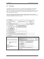
Preface
This maintenance manual describes how to perform hardware service maintenance for the
Toshiba Personal Computer PORTEGE R100, referred to as PORTEGE R100 in this manual.
The procedures described in this manual are intended to help service technicians isolate
faulty Field Replaceable Units (FRUs) and replace them in the field.
SAFETY PRECAUTIONS
Four types of messages are used in this manual to bring important information to your
attention. Each of these messages will be italicized and identified as shown below.
DANGER: “Danger” indicates the existence of a hazard that could result in death or
serious bodily injury, if the safety instruction is not observed.
WARNING: “Warning” indicates the existence of a hazard that could result in bodily
injury, if the safety instruction is not observed.
CAUTION: “Caution” indicates the existence of a hazard that could result in property
damage, if the safety instruction is not observed.
NOTE: “Note” contains general information that relates to your safe maintenance
service.
Improper repair of the computer may result in safety hazards. Toshiba requires service
technicians and authorized dealers or service providers to ensure the following safety
precautions are adhered to strictly.
Be sure to fasten screws securely with the right screwdriver. Be sure to use the PH
Point size “0” and “1” screwdrivers complying with the ISO/DIS 8764-1:1996. If a
screw is not fully fastened, it could come loose, creating a danger of a short circuit,
which could cause overheating, smoke or fire.
If you replace the battery pack or RTC battery, be sure to use only the same model
battery or an equivalent battery recommended by Toshiba. Installation of the wrong
battery can cause the battery to explode.
PORTEGE R100 Maintenance Manual (960-440)
iii
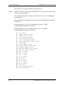
The manual is divided into the following parts:
Chapter 1
Hardware Overview describes the PORTEGE R100 system unit and
each FRU.
Chapter 2
Troubleshooting Procedures explains how to diagnose and resolve
FRU problems.
Chapter 3
Test and Diagnostics describes how to perform test and diagnostic
operations for maintenance service.
Chapter 4
Replacement Procedures describes the removal and replacement of the
FRUs.
Appendices
The appendices describe the following:
❑
❑
❑
❑
❑
❑
❑
❑
❑
iv
Handling the LCD module
Board layout
Pin assignment
Keyboard scan/character codes
Key layout
Wiring diagrams
BIOS/KBC/EC Update
Reliability
Key FD
PORTEGE R100 Maintenance Manual (960-440)
Conventions
This manual uses the following formats to describe, identify, and highlight terms and
operating procedures.
Acronyms
On the first appearance and whenever necessary for clarification acronyms are enclosed in
parentheses following their definition. For example:
Read Only Memory (ROM)
Keys
Keys are used in the text to describe many operations. The key top symbol as it appears on
the keyboard is printed in boldface type.
Key operation
Some operations require you to simultaneously use two or more keys. We identify such
operations by the key top symbols separated by a plus (+) sign. For example, Ctrl + Pause
(Break) means you must hold down Ctrl and at the same time press Pause (Break). If
three keys are used, hold down the first two and at the same time press the third.
User input
Text that you are instructed to type in is shown in the boldface type below:
DISKCOPY A: B:
The display
Text generated by the PORTEGE R100 that appears on its display is presented in the type
face below:
Format complete
System transferred
PORTEGE R100 Maintenance Manual (960-440)
v
Table of Contents
Chapter 1
Hardware Overview
1.1
Features ...................................................................................................................... 1-1
1.2
1.8-inch Hard Disk Drive........................................................................................... 1-9
1.3
Keyboard.................................................................................................................. 1-11
1.4
TFT Color Display................................................................................................... 1-12
1.5
Power Supply ........................................................................................................... 1-14
1.6
Batteries ................................................................................................................... 1-15
1.7
AC Adapter .............................................................................................................. 1-18
Chapter 2
Troubleshooting Procedures
2.1
Troubleshooting ......................................................................................................... 2-1
2.2
Troubleshooting Flowchart........................................................................................ 2-2
2.3
Power Supply Troubleshooting.................................................................................. 2-6
2.4
System Board Troubleshooting................................................................................ 2-16
2.5
USB 3.5” FDD Troubleshooting.............................................................................. 2-28
2.6
1.8” HDD Troubleshooting...................................................................................... 2-31
2.7
Keyboard Troubleshooting ...................................................................................... 2-36
2.8
Display Troubleshooting.......................................................................................... 2-37
2.9
Touch Pad ................................................................................................................ 2-39
2.10
Modem ..................................................................................................................... 2-40
2.11
LAN ......................................................................................................................... 2-42
2.12
Sound ....................................................................................................................... 2-44
2.13
SD card slot.............................................................................................................. 2-46
2.14
Wireless LAN Troubleshooting............................................................................... 2-47
vi
PORTEGE R100 Maintenance Manual (960-440)
Chapter 3
Tests and Diagnostics
3.1
The Diagnostic Test ................................................................................................... 3-1
3.2
Executing the Diagnostic Test ................................................................................... 3-3
3.3
Subtest ....................................................................................................................... 3-7
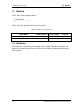
3.4
System Test................................................................................................................ 3-9
3.5
Memory Test............................................................................................................ 3-12
3.6
Keyboard Test.......................................................................................................... 3-14
3.7
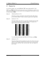
Display Test ............................................................................................................. 3-17
3.8
USB Floppy Disk Test ............................................................................................. 3-20
3.9
Hard Disk Test ......................................................................................................... 3-22
3.10
Real Timer Test........................................................................................................ 3-25
3.11
NDP Test.................................................................................................................. 3-27
3.12
Expansion Test......................................................................................................... 3-28
3.13
Wireless LAN Test Program.................................................................................... 3-30
3.14
Wireless LAN Test (Atheros) ................................................................................. 3-35
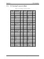
3.15
3.15 Wireless LAN Test (Calexico)......................................................................... 3-38
3.16
Sound/LAN/Modem Test......................................................................................... 3-39
3.17
Error Status Code..................................................................................................... 3-39
3.18
HDC Status .............................................................................................................. 3-44
3.19
FDD Cleaning .......................................................................................................... 3-46
3.20
Log Utilities ............................................................................................................. 3-47
3.21
Running Test............................................................................................................ 3-49
3.22
Floppy Disk Drive Utilities...................................................................................... 3-51
3.23
System Configuration .............................................................................................. 3-57
3.24
SETUP ..................................................................................................................... 3-59
Chapter 4
Replacement Procedures
4.1
Overview.................................................................................................................... 4-1
4.2
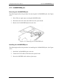
Battery pack/PC card ................................................................................................. 4-8
4.3
PC card/SD memory card ........................................................................................ 4-10
4.4
Memory Module ...................................................................................................... 4-12
PORTEGE R100 Maintenance Manual (960-440)
vii
4.5
HDD......................................................................................................................... 4-14
4.6
Keyboard/Bottom cover........................................................................................... 4-17
4.7
Touch pad................................................................................................................. 4-22
4.8
MDC board/HDD cable ........................................................................................... 4-23
4.9
Speaker/RTC battery................................................................................................ 4-25
4.10
Wireless LAN board ................................................................................................ 4-28
4.11
PC card slot .............................................................................................................. 4-31
4.12
LAN/MODEM jack ................................................................................................. 4-32
4.13
Sound board ............................................................................................................. 4-33
4.14
System board/FAN .................................................................................................. 4-34
4.15
LED SW membrane ................................................................................................. 4-38
4.16
LCD mask/FL inverter/LCD.................................................................................... 4-39
4.17
LCD cable/Wireless LAN cable/Antenna cover...................................................... 4-43
4.18
Hinge........................................................................................................................ 4-48
4.19
Fluorescent Lamp..................................................................................................... 4-50
Appendices
Appendix A
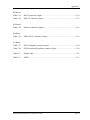
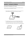
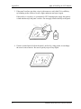
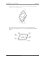
Handling the LCD Module ........................................................................ A-1
Appendix B
Board Layout ............................................................................................. B-1
Appendix C
Pin Assignment .......................................................................................... C-1
Appendix D
Keyboard Scan/Character Codes ............................................................... D-1
Appendix E
Key Layout..................................................................................................E-1
Appendix F
BIOS/KBC/EC Update ...............................................................................F-1
Appendix G
Reliability................................................................................................... G-1
Appendix H
Key FD....................................................................................................... H-1
viii
PORTEGE R100 Maintenance Manual (960-440)
Chapter 1
Hardware Overview
1 Hardware Overview
1
1-ii
Hardware Overview
PORTEGE R100 Maintenance Manual (960-440)
1 Hardware Overview
Chapter 1
Contents
1.1
Features ...................................................................................................................... 1-1
1.2
1.8-inch Hard Disk Drive........................................................................................... 1-9
1.3
Keyboard.................................................................................................................. 1-11
1.4
TFT Color Display................................................................................................... 1-12
1.4.1
LCD Module ...................................................................................... 1-12
1.4.2
FL Inverter Board............................................................................... 1-13
1.5
Power Supply ........................................................................................................... 1-14
1.6
Batteries ................................................................................................................... 1-15
1.7
1.6.1
Main Battery....................................................................................... 1-15
1.6.2
Battery Charging Control ................................................................... 1-17
1.6.3
RTC battery ........................................................................................ 1-17
AC Adapter .............................................................................................................. 1-18
PORTEGE R100 Maintenance Manual (960-440)
1-iii
1 Hardware Overview
Figures
Figure 1-1
Front of the computer..................................................................................... 1-4
Figure 1-2
System units configuration ............................................................................ 1-4
Figure 1-3
System Block Diagram .................................................................................. 1-5
Figure 1-4
1.8-inch HDD................................................................................................. 1-9
Tables
Table 1-1
1.8-inch HDD dimensions ............................................................................. 1-9
Table 1-2
1.8-inch HDD Specifications ....................................................................... 1-10
Table 1-3
LCD module specifications.......................................................................... 1-12
Table 1-4
FL inverter board specifications .................................................................. 1-13
Table 1-5
Power supply output specifications ............................................................. 1-14
Table 1-6
Battery specifications................................................................................... 1-16
Table 1-7
Time required for charges of main battery .................................................. 1-17
Table 1-8
RTC battery charging/data preservation time .............................................. 1-17
Table 1-9
AC adapter specifications ............................................................................ 1-18
1-iv
PORTEGE R100 Maintenance Manual (960-440)
1.1 Features
1
1 Hardware Overview
Features
1.1
Features
The PORTEGE R100 is an ultra thin and lightweight PC realizing cable-less environment on
a table by wireless function with an Intel Pentium® M processor realizing high performance.
❑ Microprocessor
Pentium® M
A 900/600MHz Pentium® M processor with a 400MHz external clock, 100MHz
bus and 1.2/1.05V core operation.
❑ Cache memory
A Pentium® M has 32KB primary cache and 1MB secondary cache (in CPU)
❑ Memory
One expansion memory module can be installed to provide a maximum of 1024MB.
128MB, 256MB and 512MB are provided for Memory.
❑ VRAM
32MB VRAM in Trident XP4m.
❑ HDD
40GB/30GB/20GB internal drive of 1.8-inch, 8.0mm height or 20GB internal drive of
1.8-inch, 5.0mm height.
❑ USB FDD
Three-mode 3.5 inch USB FDD supporting 720KB, 1.2MB and 1.44MB formats is
prepared as option.
❑ Display
LCD
Built-in 12.1 inch, 262,144 colors, XGA (1024×768 dots), thin type low temperature
poly- silicon TFT color display. Video controller is included in North Bridge chip.
CRT
Supported via an RGB connector
PORTEGE R100 Maintenance Manual (960-440)
1-1
1 Hardware Overview
1.1 Features
❑ Keyboard
Keyboards has 84(US)/85(UK)-key and supports Windows key.
❑ Touch pad
Touch pad is installed as a pointing device.
❑ Battery
The RTC battery is mounted inside computer.
The main battery is a detachable lithium polymer main battery (10.8V-1,950mAh)
and the RTC battery is a lithium ion battery(2.4V-15mAH).
❑ USB (Universal Serial Bus)
Six USB ports supporting USB 2.0. Two of these are occupied and others are usable.
❑ PC card slot
A PC card Type I or II is acceptable. Supports ToPIC-100 (3.3V/CardBus).
❑ SD card slot
One SD card slot.
❑ Sound system
Incorporates an internal monaural speaker, external monaural microphone connector
and stereo headphone connector.
❑ One touch button
Internet button and Mail button are installed.
❑ Built-in Modem
The computer contains a MDC, enabling data and fax communication. It supports
ITU-TV.90. The transfer rates are 56 Kbps for data reception, 33.6 Kbps for data
transmission, and 14,400 bps for fax transmission. However, the actual speed
depends on the line quality. The RJ11 modem jack is used to accommodate a
telephone line.
❑ LAN
The internal LAN supports 10/100Mbit Ethernet.
1-2
PORTEGE R100 Maintenance Manual (960-440)
1.1 Features
1 Hardware Overview
❑ Wireless LAN
The internal wireless LAN supports Mini PCI Type III(802.11ab) made by Agere.
PORTEGE R100 Maintenance Manual (960-440)
1-3
1 Hardware Overview
1.1 Features
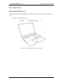
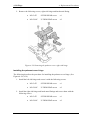
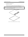
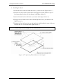
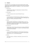
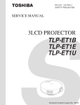
Figure 1-1 shows the front of the computer and Figure 1-2 shows the system units
configuration.
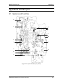
Figure 1-1 Front of the computer
External microphone
Wireless LAN card
FGOFL*
board
PJ998
Headphone
PJ997 PJ999
PJ8770
RTC battery
PJ8760
Battery
PJ8810
DC-IN
PJ8800
LCD
PJ5600
FL inverter
PJ5601
CRT
PJ5620
LED
PJ7
Memory
PJ1002
PJ9
PJ100
PJ501
FGOSC*
board
Fan
PJ500
PJ351
FGOMI*
board
PJ17
PJ1
FGOWS*
board
PJ1
PJ1
Docking I/F
PJ6002
Speaker
PJ4
USB1
PJ5
USB2
PJ4100
Network
PJ2210
SD card
PJ325
Debug port
System board
PJ11
PC card
PJ445
Keyboard
PJ334
(When there is no
wireless LAN, the
FGOWS card is
used instead of the
FGOMI card.)
PJ3
Pad
PJ1
PJ3
PJ2
MDC
HDD
FGOHD board
Figure 1-2 System units configuration
1-4
PORTEGE R100 Maintenance Manual (960-440)
1.1 Features
1 Hardware Overview
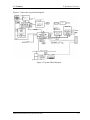
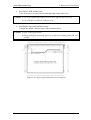
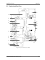
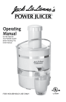
Figure 1-3 shows the system block diagram.
Figure 1-3 System Block Diagram
PORTEGE R100 Maintenance Manual (960-440)
1-5
1 Hardware Overview
1.1 Features
The PC contains the following components.
❑ CPU
Pentium® M
•
•
•
A 900/600MHz Centrino processor with a 400MHz external clock, 100MHz
bus and 1.2V/1.05 core operation voltage (built-in NDP).
Internal cache memory: 32KB Data and 32KB Instruction, Write-Back
Secondary cache memory: 1MB (in CPU)
❑ Memory
One memory slot capable of accepting 256MB-memory module for a maximum of
512MB.
• 2.5V operation
• 140-pin exclusive memory board
• Access time : 6ns
• Memory Supporting PC-2100(Operation is PC100)
❑ BIOS ROM (Flash memory)
•
•
•
•
1-6
4Mbit (256K×16-bit chip)
− 64KB used for logo
− 64KB used for setup and checksum
− 128KB used for system BIOS
− 64KB used for VGA-BIOS
− 64KB used for ACPI
− 8KB used for PnP
− 8KB used for password security
− 16KB used for booting
− 64KB used for LAN
− 32KB are reserved
5.0V operation
Access time : 120 ns or 90 ns
Data transfer: 8-bit
PORTEGE R100 Maintenance Manual (960-440)
1.1 Features
1 Hardware Overview
❑ PCI chipset
This gate array incorporates the following elements and functions
•
North Bridge (Intel-made Odem MCH-M)
− Pentium® M processor and Mobile Northwood processor supported
− Maximum capacity of DDR200 or DDR266 is 1GBmax
− DRAM control
− Complies with AGP V2.0 x 4 modes
− Complies with PCI R2.2
− Complies with APCI 1.0b
− Geyserville III supported
− Intel SpeedStep Technology supported
− 593-ball 37.5x37.5mm Micro-FCBGA package
•
South Bridge (Intel-made ICH4-M)
− PCI 3.3V/5V tolerance interface
− Provides Steerable PCI interrupts for PCI device Plug-and-Play
− Enhanced DMA controller
− Interrupt controller
− Counter/timers
− Distributed DMA supported
− PC/PCI DMA supported
− Serial IRQ supported
− Low Pin Count (LPC) host controller
− Plug-and-Play supported
− ACPI supporting features
− Built-in PCI IDE controller
− USB interface (6 x USB2.0 ports)
− SMBus interface
− Super I/O interface
− Audio system
− SW modem interface
− 421-ball (31mm x 31mm) BGA package
❑ VGA controller
Included in North Bridge
❑ PC card controller (Amkor-made YEBISU_SS)
•
•
•
•
PCI interface (PCI Rev.2.2)
Chipset interface
CardBus/PC Card controller (Yenta2 Ver.2.2) 1 slots
SD card controller (SDHC Ver.1.2)
PORTEGE R100 Maintenance Manual (960-440)
1-7
1 Hardware Overview
•
•
•
•
•
•
•
1.1 Features
SDIO card controller (Ver.1.1)
SmartMedia controller (SMHC Ver 01/SMIL1.0)
SmartCard I/F
SIO (UART) controller (MS Debug Port Specification Ver.1.0)
Docking station interface
External device interface
1.0mm pitch 256pin/17mm PBGA package
❑ Other main system chips
•
•
•
•
EC/KBC (Mitsubishi-made LPC microcontroller M306K5F8LRP x 1)
PSC (TMP87PM48U x 1)
Temperature sensor (ADM1032 x 1)
E2PROM (BR93LC46F-Q (used for LAN MAC address))
❑ Modem controller
Supported by MDC. Using of the secondary AC97 Line
❑ LAN controller (Kinnereth-made Intel:82550PM)
Controls LAN and supports 10/100Base-T.
1-8
PORTEGE R100 Maintenance Manual (960-440)
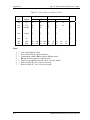
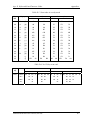
1.2 1.8-inch Hard Disk Drive
1.2
1 Hardware Overview
1.8-inch Hard Disk Drive
A compact, high-capacity HDD with a height of 5.0/8.0mm. Contains a 1.8-inch magnetic
disk and magnetic heads.
Figure 1-4 shows a view of the 1.8-inch HDD and Tables 1-1 and 1-2 list the specifications.
Figure 1-4 1.8-inch HDD
Table 1-1 1.8-inch HDD dimensions
Standard value
Parameter
TOSHIBA
TOSHIBA
TOSHIBA
TOSHIBA
HDD1422
MK2003GAH
HDD1384
HDD1524
Outline
Width (mm)
54.0
54.0
54.0 0.2
54.0 0.2
dimensions
Height (mm)
5.0 0.15
8.0
8.0 0.15
8.0 0.15
Depth (mm)
78.5 0.3
78.5
78.5 0.3
78.5 0.3
51max
62max
62max
62max
Weight (g)
PORTEGE R100 Maintenance Manual (960-440)
1-9
1 Hardware Overview
1.2 1.8-inch Hard Disk Drive
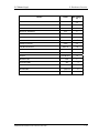
Table 1-2 1.8-inch HDD Specifications
Specification
Parameter
TOSHIBA
TOSHIBA
TOSHIBA
TOSHIBA
HDD1422
MK2003GAH
HDD1384
HDD1524
Storage size
(formatted)
20GB
20GB
30GB
40GB
Speed (RPM)
4,200 0.1
4,200
4,200
4,200 0.1
125.5 to 253.1
115.6 to 204.4
114.8 to 222.7
125.5 to 253.1
100
100
100
100
Track/mm(TPI)
3465
2237 (56.8K) max.
3039
3465
Bit/mm
27.4K
24.4K(621K) max.
24.1K
27.4K
Track to track
3
3
3
3
Average time
15
15
15
15
Max seek
26
26
26
26
3.5 typical
3.5 typical
3.5 typical
3.5 typical
20 max
20 max
20 max
20 max
Data transfer speed
(Mbits/s)
Interface transfer
rate (MB/s)
Track density
Access time (msec)
Start time (sec)
1-10
PORTEGE R100 Maintenance Manual (960-440)
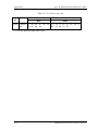
1.3 Keyboard
1.3
1 Hardware Overview
Keyboard
The keyboard is mounted 84(US)/85(UK) keys that consist of character key and control key,
and in conformity with JIS. The keyboard is connected to membrane connector on the system
board and controlled by the keyboard controller. See Appendix E about a layout of the
keyboard.
PORTEGE R100 Maintenance Manual (960-440)
1-11
1 Hardware Overview
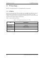
1.4
1.4 TFT Color Display
TFT Color Display
The TFT color display consists of a LCD module and FL inverter board.
1.4.1 LCD Module
The LCD module used for the TFT color display uses a backlight as the light source and can
display images and characters of 262,144 colors with 1024×768 resolution. The video
controller is incorporated into the North Bridge (M1644M) chip and can control both internal
and external XGA-support displays simultaneously.
Table 1-5 shows list the specifications.
Table 1-3 LCD module specifications (12.1 TFT)
Item
Specifications
G33C0000U
Number of Dots
Dot spacing (mm)
Display range (mm)
Outline
1024×768
0.24(H) x 0.24(V)
245.76(H) x 184.32(V)
264.4(w) x 197.5(H) x 5.35Max(D)
dimensions
1-12
PORTEGE R100 Maintenance Manual (960-440)
1.4 TFT Color Display
1 Hardware Overview
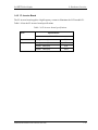
1.4.2 FL Inverter Board
The FL inverter board supplies a high frequency current to illuminate the LCD module FL.
Table 1-4 lists the FL inverter board specifications.
Table 1-4 FL inverter board specifications
Item
Specifications
UA2040P02
Input
Voltage
(V)
DC 5
Output
Voltage
(V)
750
Current
MAX (mA)
4.22
Current
MIN (mA)
0.412
PORTEGE R100 Maintenance Manual (960-440)
1-13
1 Hardware Overview
1.5
1.5 Power Supply
Power Supply
The power supply supplies eight different voltages to the system board.
The power supply microcontroller has the following functions.
1. Judges that the DC power supply (AC adapter) is connected to the computer.
2. Detects DC output and circuit malfunctions.
3. Controls the battery icon, and DC IN icon.
4. Turns the battery charging system on and off and detects a fully charged battery.
5. Turns the power supply on and off.
6. Provides more accurate detection of a low battery.
7. Calculates the remaining battery capacity.
8. Controls the transmission of the status signal of the main battery.
Table 1-5 lists the power supply output specifications.
Table 1-5 Power supply output specifications
Device
CPU
Name
DC Voltage
(V)
PPV
1.000 0.748
MCH-M
MCH1R2-P1V
1.2
PTV
1.075
GPU
2R5-P2V
2.5
MCH-M,SDRAM
2R5-B2V
2.5
SDRAM
1R25-B1V
1.25
CPU,MCH-M,ICH4-M
(1R25M-B1V)
GPU
PGV
1.2-1.5
LAN-E3V
3.3
ICH4-M,EC/KBC
S3V
3.3
YEBISUSS,PC Card,MDC
B3V
3.3
Clock Generator,ADM1032,ICH4-M,FWH,Mini PCI,
GPU,LCD,AD1981B,HDD
P3V
3.3
ICH4-M,KINNERETH
1-14
PORTEGE R100 Maintenance Manual (960-440)
1.5 Power Supply
1 Hardware Overview
Name
DC Voltage
(V)
SD-B3V
3.3
USB
E5V
5
PC Card
B5V
5
KB,LED,FL INVERTER
P5V
5
DOCK
D-E3V
3.3
DOCK
D-E5V
5
A4R7-P4V
4.7
A-P3V
3.3
1R8-P1V
1.8
Device
SD
AD1981B
Headphone,Ext-Mic
CPU,MCH-M,ICH4-M
MCH-M,ICH4-M,GPU
1R5-P1V
1.5
ICH4-M
1R5-S1V
1.5
ICH4-M
LAN1R5-E1V
1.5
MAX6501,LED
M5V
ICH4-M,EC/KBC
S5V
PSC
MCV
AD1981B,MIC
A4R7-P4V
ICH4-M
R3V
PORTEGE R100 Maintenance Manual (960-440)
5
5
5
4.7
2.0 - 3.3
1-15
1 Hardware Overview
1.6
1.6 Batteries
Batteries
The PC has the following two batteries.
❑ Main battery
❑ Real time clock (RTC) battery
Table 1-6 lists the specifications for these two batteries.
Table 1-6 Battery specifications
Battery Name
Main battery
(XM2043P02)
Real time clock (RTC) battery
Battery Element
Output Voltage
Capacity
Lithium ion
10.8V
1600mAh
Nickel hydride
2.4 V
15 mAh
1.6.1 Main Battery
The main battery is the primary power supply for the computer when the AC adapter is not
connected. In resume (instant recovery) mode, the main battery maintains the current status
of the computer.
1-16
PORTEGE R100 Maintenance Manual (960-440)
1.6 Batteries
1 Hardware Overview
1.6.2 Battery Charging Control
Battery charging is controlled by a power supply microprocessor. The power supply
microprocessor controls power supply and detects a full charge when the AC adaptor and
battery are connected to the computer. The system charges the battery using quick charge or
trickle charge.
❑ Quick Battery Charge
When the AC adapter is connected, normal charging is used while the system is
turned on and quick charge is used while the system is turned off or in suspend mode.
(See Table 1-7)
Table 1-7 Time required for charges of main battery
Charging Time
Normal charge
Quick charge
About 2 to 4 hours
About 2 hours
Quick battery charge is stopped in the following cases.
1. The main battery is fully charged
2. The main battery is removed
3. Main battery or AC adapter voltage is abnormal
4. Charging current is abnormal
❑ Trickle charge
When the main battery is fully charged and the AC adapter is plugged in, the power
supply microcontroller automatically switches from quick charge to trickle charge.
1.6.3 RTC Battery
The RTC battery provides the power supply to maintain the date, time, and other system
information in memory. Table 1-8 lists the battery charging time and data preservation times.
Table 1-8 RTC battery charging/data preservation time
Charging
AC adapter or main battery in use
Data preservation time (when fully charged)
PORTEGE R100 Maintenance Manual (960-440)
Time
8 hours (approx )
1 month
1-17
1 Hardware Overview
1.7
1.7 AC Adapter
AC Adapter
The AC adapter is also used to charge the battery.
Table 1-9 lists the AC adapter specifications.
Table 1-9 AC adapter specifications
Parameter
Input voltage
Input frequency
Input current(MAX)
1-18
Specification
AC 100 to 240V
50Hz/60Hz
1.2A (100VAC)
Output voltage
DC 15V
Output current
3.0A
PORTEGE R100 Maintenance Manual (960-440)
Chapter 2
Troubleshooting Procedures
2 Troubleshooting Procedures
2
2-ii
PORTEGE R100 Maintenance Manual (960-440)
2 Troubleshooting Procedures
Chapter 2
Contents
2.1
Troubleshooting ......................................................................................................... 2-1
2.2
Troubleshooting Flowchart........................................................................................ 2-2
2.3
Power Supply Troubleshooting.................................................................................. 2-6
2.4
2.5
2.6
2.7
Procedure 1
Power Status Check ............................................................... 2-7
Procedure 2
Error Code Check .................................................................. 2-9
Procedure 3
Connection Check................................................................ 2-14
Procedure 4
Quick Charge Check ............................................................ 2-14
Procedure 5
Replacement Check ............................................................. 2-15
System Board Troubleshooting................................................................................ 2-16
Procedure 1
Message Check .................................................................... 2-17
Procedure 2
Debug Port Check on Boot Mode........................................ 2-19
Procedure 3
Diagnostic Test Program Execution Check ......................... 2-27
Procedure 4
Replacement Check ............................................................. 2-27
USB 3.5” FDD Troubleshooting.............................................................................. 2-28
Procedure 1
FDD Head Cleaning Check ................................................. 2-28
Procedure 2
Diagnostic Test Program Execution Check ......................... 2-29
Procedure 3
Connector Check and Replacement Check.......................... 2-30
1.8” HDD Troubleshooting...................................................................................... 2-31
Procedure 1
Partition Check..................................................................... 2-31
Procedure 2
Message Check .................................................................... 2-32
Procedure 3
Format Check....................................................................... 2-33
Procedure 4
Diagnostic Test Program Execution Check ......................... 2-34
Procedure 5
Connector Check and Replacement Check.......................... 2-35
Keyboard Troubleshooting ...................................................................................... 2-36
Procedure 1
Diagnostic Test Program Execution Check ......................... 2-36
Procedure 2
Connector Check and Replacement Check.......................... 2-36
PORTEGE R100 Maintenance Manual (960-440)
2-iii
2 Troubleshooting Procedures
2.8
2.9
2.10
2.11
2.12
2.13
2.14
2-iv
Display Troubleshooting.......................................................................................... 2-37
Procedure 1
Diagnostic Test Program Execution Check ......................... 2-37
Procedure 2
Connector and Cable Check................................................. 2-37
Procedure 3
Fuse connection check ......................................................... 2-37
Procedure 4
Replacement Check ............................................................. 2-38
Touch Pad ................................................................................................................ 2-39
Procedure 1
Diagnostic Test Program Execution Check ......................... 2-39
Procedure 2
Connector checking and replacement checking................... 2-38
Procedure 3
Replacement Check ............................................................. 2-39
Modem ..................................................................................................................... 2-40
Procedure 1
Diagnostic Test Program Execution Check ......................... 2-40
Procedure 2
Connector checking and replacement checking................... 2-41
LAN ......................................................................................................................... 2-42
Procedure 1
Diagnostic Test Program Execution Check ......................... 2-42
Procedure 2
Connector checking and replacement checking................... 2-43
Sound ....................................................................................................................... 2-44
Procedure 1
Diagnostic Test Program Execution Check ......................... 2-44
Procedure 2
Connector Check.................................................................. 2-44
Procedure 3
Replacement Check ............................................................. 2-45
SD card slot.............................................................................................................. 2-46
Procedure 1
Check on Windows .............................................................. 2-46
Procedure 2
Connector/ Replacement Check........................................... 2-46
Wireless LAN Troubleshooting............................................................................... 2-47
Procedure 1
Trancemitting-Receiving Check .......................................... 2-47
Procedure 2
Antennas’ Connection Check .............................................. 2-48
Procedure 3
Antenna Check..................................................................... 2-49
Procedure 4
Replacement Check ............................................................. 2-50
PORTEGE R100 Maintenance Manual (960-440)
2 Troubleshooting Procedures
Figures
Figure 2-1
Troubleshooting flowchart(1/2) ..................................................................... 2-3
Figure 2-2
Troubleshooting flowchart(2/2) ..................................................................... 2-4
Figure 2-3
A set of tool for debug port test ................................................................... 2-19
Figure 2-4
Antenna Test jig........................................................................................... 2-49
Tables
Table 2-1
Battery icon.................................................................................................... 2-7
Table 2-2
DC IN icon..................................................................................................... 2-7
Table 2-3
D port status ................................................................................................. 2-21
Table 2-4
FDD error code and status ........................................................................... 2-29
Table 2-5
1.8” HDD error code and status................................................................... 2-34
PORTEGE R100 Maintenance Manual (960-440)
2-v
2 Troubleshooting Procedures
2-vi
PORTEGE R100 Maintenance Manual (960-440)
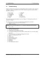
2.1 Troubleshooting
2 Troubleshooting
2
2.1
Troubleshooting
Chapter 2 describes how to determine which Field Replaceable Unit (FRU) in the computer is
causing the computer to malfunction. (The “FRU” means the replaceable unit in the field.)
The FRUs covered are:
1.
2.
3.
4.
5.
6.
Power supply
System board
3.5" USB FDD
1.8" HDD
Keyboard
Display
7. Touch pad
8. Modem
9. LAN
10. Sound
11. SD card slot
12. Wireless LAN
The Detailed replacement procedures are given in Chapter 4. Test Program operations are
described in Chapter 3.
The following tools are necessary for implementing the Diagnostics procedures:
1. Diagnostics Disk (Test program for maintenance)
2. Phillips screwdrivers
NOTE: Be sure to use the PH point size “0” screwdriver complying with the ISO/DIS
8764-1:1996.
3.
4.
5.
6.
Toshiba MS-DOS system FD
Work disk (for FDD testing)
Cleaning disk kit (for FDD head cleaning)
A set of tools for debug port test (test cable, test board, RS-232C cross cable, display,
D port FD)
7. PC with a serial port (for displaying debug port test result)
8. Wraparound connector for PC card
9. Tester
10. External CRT
11. External USB Keyboard
12. External USB mouse
13. Headphone
14. Microphone
15. LAN wraparound connector
PORTEGE R100 Maintenance Manual (960-440)
2-1
2 Troubleshooting
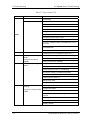
2.2
2.2 Troubleshooting Flowchart
Troubleshooting Flowchart
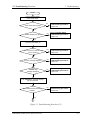
Use the flowchart in Figure 2-1 as a guide for determining which FRU malfunctions. Before
going through the flowchart steps, check the following:
®
Make sure that Toshiba Windows XP is installed on the hard disk. Non-Toshiba
operating systems can cause the computer malfunction.
Make sure all optional equipment is removed from the computer.
Make sure the USB FDD is empty.
2-2
PPORTEGE R100 Maintenance Manual (960-440)
2.2 Troubleshooting Flowchart
2 Troubleshooting
START
Connect the AC adapter
to the DC IN socket.
No
Does the DC IN icon glow?
Perform the Power Supply
Troubleshooting Procedures
in section 2.3.
Yes
Does the Battery icon glow?
No
Perform the Power Supply
Troubleshooting Procedures
in section 2.3.
Yes
Turn the Power Switch on.
Yes
Does the DC IN icon flash when the
power is turned on?
Perform the Power Supply
Troubleshooting Procedures
in section 2.3.
No
Is an error message displayed?
Yes
Perform the System Board
Troubleshooting Procedures
in section 2.4.
No
Is the
“Toshiba” logo
message displayed?
No
Perform the Display
Troubleshooting Procedures
in section 2.8.
No
Perform the 1.8” HDD
Troubleshooting Procedures
in section 2.6.
Yes
If the “Password=” message displays,
type the password.
Are Toshiba Windows XP being
loaded?
Yes
1
Figure 2-1 Troubleshooting flowchart (1/2)
PORTEGE R100 Maintenance Manual (960-440)
2-3
2 Troubleshooting
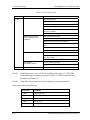
2.2 Troubleshooting Flowchart
1
Do typed characters
appear correctly?
No
Perform the Keyboard
Troubleshooting Procedures
in section 2.7.
No
Perform the Touch pad
Troubleshooting Procedures
in section 2.9.
Yes
Insert the diagnostic disk into USB FDD
and run the diagnostics test program.
(The reboot of the PC is needed.)
Do the touch pad work
correctly?
Yes
Insert the diagnostic disk into USB FDD
and run the diagnostics test program.
(The reboot of the PC is needed.)
No
Is the diagnostic test loaded?
Perform the 3.5” USB FDD
Troubleshooting Procedures
in section 2.5.
Yes
Perform each test of the diagnostic test.
Is an error
detected by any of the
diagnostic test?
Yes
After conforming which diagnostic
test has detected an error, perform
the appropriate procedures as
outlined below.
No
System is normal.
END
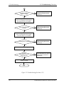
Figure 2-2 Troubleshooting flowchart (2/2)
2-4
PPORTEGE R100 Maintenance Manual (960-440)
2.2 Troubleshooting Flowchart
2 Troubleshooting
If the diagnostics program cannot detect an error, the problem may be intermittent. The Test
program should be executed several times to isolate the problem. Check the Log Utilities
function to confirm which diagnostic test detected an error(s), then perform the appropriate
troubleshooting procedures as follows:
1. If an error is detected on the system test, memory test, display test, Expansion test,
Real timer test or Sound/LAN/modem test, perform the System board Troubleshooting
Procedures in Section 2.4.
2. If an error is detected on the floppy disk test, perform the USB FDD Troubleshooting
Procedures in Section 2.5.
3. If an error is detected on the hard disk test, perform the HDD Troubleshooting
Procedures in Section 2.6.
4. If an error is detected on the keyboard test, perform the Keyboard Troubleshooting
Procedures in Section 2.7.
5. If an error is detected on the display test, perform the Display Troubleshooting
Procedures in Section 2.8.
PORTEGE R100 Maintenance Manual (960-440)
2-5
2 Troubleshooting
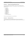
2.3
2.3 Power Supply Troubleshooting
Power Supply Troubleshooting
The power supply controller controls many functions and components. To determine if the
power supply is functioning properly, start with Procedure 1 and continue with the other
Procedures as instructed. The procedures described in this section are:
Procedure 1: Power supply icon Check
Procedure 2: Error Code Check
Procedure 3: Connection Check
Procedure 4: Quick Charge Check
Procedure 5: Replacement Check
2-6
PPORTEGE R100 Maintenance Manual (960-440)
2.3 Power Supply Troubleshooting
Procedure 1
2 Troubleshooting
Power supply icon Check
The following two icons indicate the power supply status:
Battery icon
DC IN icon
The power supply controller uses the power supply status with the Battery icon and the DC IN
icon as listed in the tables below.
Table 2-1 Battery icon
Battery icon
Power supply status
Lights orange
Battery is charged and the external DC is input. It has no relation with
ON/OFF of the system power.
Lights green
Battery is fully charged and the external DC is input. It has no relation
with ON/OFF of the system power.
Blinks orange
(even intervals)
The battery level is low while the system power is ON.
Flashes orange
The battery level is low and the power switch is pressed on in the
battery driving.
Doesn’t light
Any condition other than those above.
Table 2-2 DC IN icon
DC IN icon
Power supply status
Lights green
DC power is being supplied from the AC adapter.
Blinks orange
Power supply malfunction* 3
Doesn’t light
Any condition other than those above.
*3 When the power supply controller detects a malfunction, the DC IN icon blinks
orange. It shows an error code.
PORTEGE R100 Maintenance Manual (960-440)
2-7
2 Troubleshooting
2.3 Power Supply Troubleshooting
When icons are blinking, perform the following procedure.
1.
Remove the battery pack and the AC adapter and cut off the power supply to the
computer by force.
2.
Re-attach the battery pack and the AC adapter.
If icon s are still blinking after the operation above, check the followings:
Check 1
If the DC IN icon blinks orange, go to Procedure 2.
Check 2
If the DC IN icon does not light, go to Procedure 3.
Check 3
If the battery icon does not light orange or green, go to Procedure 4.
CAUTION: Use a recommended AC adapter (ADP-45W) only.
2-8
PPORTEGE R100 Maintenance Manual (960-440)
2.3 Power Supply Troubleshooting
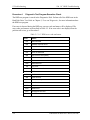
Procedure 2
2 Troubleshooting
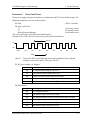
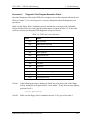
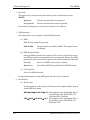
Error Code Check
If the power supply microprocessor detects a malfunction, the DC IN icon blinks orange. The
blink pattern indicates an error as shown below.
Start
Error code (8 bit)
“1”
“0”
Interval between data bits
The error code begins with LSB (Least Significant bit)
Example: Error code 11h (Error codes are given in hexadecimal format.)
Off for 2 seconds
On for one second
On for half second
On for half second
Re ad
On
1
0
0
0
1
0
0
0
D0
D1
D2
D3
D4
D5
D6
D7
Off
Start
Order
Check 1
Convert the DC IN icon blink pattern into the hexadecimal error code and
compare it to the tables below. Then go to Check 2.
DC power supply (AC adapter)
Error code
Meaning
10h
AC Adapter output voltage is over 16.5V.
11h
Commondock output voltage is over 16.5V.
12h
Current from the DC power supply is over 4.95A.
13h
Current from the DC power supply is over 0.5A when there is no load.
14h
Abnormal current has been sensed 0[A].
Main Battery
Error code
Meaning
20h
Over voltage is detected.
21h
Main battery charge current is over 4.95A.
22h
Main battery discharge current is over 0.5A when there is no load.
23h
Main battery charge current is over 2.3A.
24h
Abnormal current has been sensed 0[A].
25h
Main battery charge current is over 0.3A.
PORTEGE R100 Maintenance Manual (960-440)
2-9
2 Troubleshooting
2.3 Power Supply Troubleshooting
Second Battery
Error code
Meaning
30h
Over voltage is detected.
31h
Main battery charge current is over 4.95A.
32h
Main battery discharge current is over 0.5A when there is no load.
33h
Main battery charge current is over 2.3A.
34h
Abnormal current has been sensed 0[A].
35h
Main battery charge current is over 0.3A.
S3V output
Error code
Meaning
40h
S3V voltage is 3.14V or less when the computer is powered on/off.
45h
S3V voltage is 3.14V or less at power-on (CV support)
1R5-C1 output
Error code
Meaning
50h
1R5-C1 voltage is over 1.80V when the computer is powered on/off.
51h
1R5-C1 voltage is 1.275V or less when the computer is powered on.
52h
1R5-C1 voltage is 1.275V or less when the computer is booting up.
53h
1R5-C1 voltage is 1.275V or less while the computer is suspended.
54h
1R5-C1 voltage is abnormal during shutdown (CV support)
55h
1R5-C1 voltage is 1.275V or less at power-on (CV support)
1R8-C1 output
Error code
2-10
Meaning
60h
1R8-C1V voltage is over 2.16V when the computer is powered on/off.
61h
1R8-C1V voltage is 1.53V or less when the computer is powered on.
62h
1R8-C1V voltage is 1.53V or less when the computer is booting up.
63h
1R8-C1V voltage is 1.53V or less while the computer is suspended.
64h
1R8-C1V voltage is abnormal during shutdown (CV support)
65h
1R8-C1V voltage is 1.53V or less at power-on (CV support)
PPORTEGE R100 Maintenance Manual (960-440)
2.3 Power Supply Troubleshooting
2 Troubleshooting
PPV output
Error code
Meaning
70h
PPV voltage is over 1.80V when the computer is powered on/off.
71h
PPV voltage is 0.56V or less when the computer is powered on.
72h
PPV voltage is 0.56V or less when the computer is booting up.
73h
PPV voltage is 0.56V or more when the computer is powered off.
PGV output
Error code
Meaning
80h
PGV voltage is over 1.92V when the computer is powered on/off.
81h
PGV voltage is 0.68V or less when the computer is powered on.
82h
PGV voltage is 0.68V or less when the computer is booting up.
83h
PGV voltage is 0.68V or more when the computer is powered off.
E5V output
Error code
Meaning
90h
E5V voltage is over 6.00V when the computer is powered on.
91h
E5V voltage is 4.50V or less when the computer is powered on.
92h
E5V voltage is 4.50V or less when the computer is booting up.
93h
E5V voltage is 4.50V or less when the computer is powered off.
94h
E5V voltage is 4.50V or less while the computer is suspended.
E3V output
Error code
Meaning
A0h
E3V voltage is over 3.96V when the computer is powered on.
A1h
E3V voltage is 2.81V or less when the computer is powered on.
A2h
E3V voltage is 2.81V or less when the computer is booting up.
A3h
E3V voltage is 2.81V or less when the computer is powered off.
A4h
E3V voltage is 2.81V or less while the computer is suspended.
PORTEGE R100 Maintenance Manual (960-440)
2-11
2 Troubleshooting
2.3 Power Supply Troubleshooting
1R2-P1V output
Error code
Meaning
B0h
1R2-P1V voltage is over 1.44V when the computer is powered on.
B1h
1R2-P1V voltage is 1.02V or less when the computer is powered on.
B2h
1R2-P1V voltage is 1.02V or less when the computer is booting up.
B3h
1R2-P1V voltage is 1.02V or less when the computer is powered off.
B4h
1R2-P1V voltage is 1.02V or less while the computer is suspended.
PTV output
Error code
Meaning
C0h
PTV voltage is over 1.426V when the computer is powered on.
C1h
PTV voltage is 0.89V or less when the computer is powered on.
C2h
PTV voltage is 0.89V or less when the computer is booting up.
C3h
PTV voltage is 0.89V or less when the computer is powered off.
C4h
PTV voltage is 0.89V or less while the computer is suspended.
1R25-B1V output
Error code
Meaning
D0h
1R25-B1V voltage is over 1.50V when the computer is powered on.
D1h
1R25-B1V voltage is 1.063V or less when the computer is powered on.
D2h
1R25-B1V voltage is 1.063V or less when the computer is booting up.
D3h
1R25-B1V voltage is 1.063V or less when the computer is powered off.
D4h
1R25-B1V voltage is 1.063V or less while the computer is suspended.
2R5-B2V output
Error code
2-12
Meaning
E0h
2R5-B2V voltage is over 3.00V when the computer is powered on.
E1h
2R5-B2V voltage is 2.125V or less when the computer is powered on.
E2h
2R5-B2V voltage is 2.125V or less when the computer is booting up.
E3h
2R5-B2V voltage is 2.125V or less when the computer is powered off.
E4h
2R5-B2V voltage is 2.125V or less while the computer is suspended.
PPORTEGE R100 Maintenance Manual (960-440)
2.3 Power Supply Troubleshooting
Check 2
2 Troubleshooting
In the case of error code 10h or 12h:
Make sure the AC adapter and AC power cord are firmly plugged into the DC
IN 15 V socket and wall outlet. If the cables are connected correctly, go to the
following step:
Connect a new AC adapter and AC power cord. If the error still exists, go to
Procedure 5.
Check 3
In the case of error code 21h:
Go to Procedure 3.
Check 4
For any other errors, go to Procedure 5.
PORTEGE R100 Maintenance Manual (960-440)
2-13
2 Troubleshooting
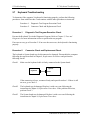
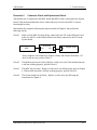
Procedure 3
2.3 Power Supply Troubleshooting
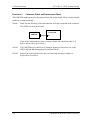
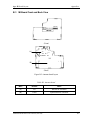
Connection Check
The wiring diagram related to the power supply is shown below:
Power
Cord
AC
adapter
System
Board
Battery pack
Any of the connectors may be disconnected. Perform starting from Check 1.
Check 1
Make sure the AC adapter and the AC power cord are firmly plugged into the DC
IN 15 V socket and wall outlet. If these cables are connected correctly, go to Check
2.
Check 2
Replace the AC adapter and the AC power cord with new ones.
•
•
Check 3
If the DC IN icon does not light, go to Procedure 5.
If the battery icon does not light, go to Check 3.
Make sure the battery pack is installed in the computer correctly. If the battery is
properly installed and the battery icon still does not light, go to Procedure 4.
Procedure 4
Quick Charge Check
Check if the power supply controller charges the battery pack properly. Perform the following
procedures:
Check 1
Make sure the AC adapter is firmly plugged into the DC IN socket.
Check 2
Make sure the battery pack is properly installed. If the battery is properly installed,
go to Check 3.
Check 3
The battery pack may be completely discharged. Wait a few minutes to charge the
battery pack while connecting the battery pack and the AC adapter. If the battery
pack is still not charged, go to Check 4.
Check 4
The battery’s temperature is too high or low. Return the temperature to normal
operating condition. If the battery pack is still not charged, go to Check 5.
Check 5
Replace the battery pack with a new one. If the battery pack is still not charged, go
to Procedure 5.
2-14
PPORTEGE R100 Maintenance Manual (960-440)
2.3 Power Supply Troubleshooting
Procedure 5
2 Troubleshooting
Replacement Check
The power is supplied to the System board by the AC adapter. If either the AC adapter or the
System board was damaged, perform the following Checks.
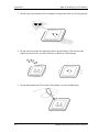
To disassemble the computer, follow the steps described in Chapter 4.
Check 1
Replace the AC adapter with a new one. If the AC adapter is still not functioning
properly, perform Check 2.
Check 2
Replace the System board with a new one.
PORTEGE R100 Maintenance Manual (960-440)
2-15
2 Troubleshooting
2.4
2.4 System board Troubleshooting
System board Troubleshooting
This section describes how to determine if the System board is defective. Start with Procedure
1 and continue with the other procedures as instructed. The procedures described in this
section are:
Procedure 1: Message Check
Procedure 2: Debug port (D port) Check on Boot Mode
Procedure 3: Diagnostic Test Program Execution Check
Procedure 4: Replacement Check
2-16
PPORTEGE R100 Maintenance Manual (960-440)
2.4 System board Troubleshooting
Procedure 1
2 Troubleshooting
Message Check
When the power is turned on, the system performs the Initial Reliability Test (IRT) installed
in the BIOS ROM. The IRT tests each IC on the System board and initializes it.
If an error message is shown on the display, perform Check 1.
If there is no error message, go to Procedure 2.
If MS-DOS or Windows® XP is properly loaded, go to Procedure 4.
Check 1
If one of the following error messages is displayed on the screen, press the F1 key
as the message instructs. These errors occur when the system configuration
preserved in the RTC memory (CMOS type memory) is not the same as the actual
configuration or when the data is lost.
If you press the F1 key as the message instructs, the SETUP screen appears to set
the system configuration. If error message (b) appears often when the power is
turned on, replace the RTC battery. If any other error message is displayed,
perform Check 2.
Check 2
(a)
*** Bad HDD type ***
Check system. Then press [F1] key ......
(b)
*** Bad RTC battery ***
Check system. Then press [F1] key ......
(c)
*** Bad configuration ***
Check system. Then press [F1] key ......
(d)
*** Bad memory size ***
Check system. Then press [F1] key ......
(e)
*** Bad time function ***
Check system. Then press [F1] key ......
(f)
*** Bad check sum (CMOS) ***
Check system. Then press [F1] key ......
(g)
*** Bad check sum (ROM) ***
Check system. Then press [F1] key ......
If the following error message is displayed on the screen press any key as the
message instructs.
The following error message appears when data stored in RAM under the resume
function is lost because the battery has become discharged or the System board is
damaged. Go to Procedure 3.
WARNING:
RESUME FAILURE.
PRESS ANY KEY TO CONTINUE.
PORTEGE R100 Maintenance Manual (960-440)
2-17
2 Troubleshooting
2.4 System board Troubleshooting
If any other error message is displayed, perform Check 3.
Check 3
The IRT checks the System board. When the IRT detects an error, the system stops
or an error message appears.
If one of the following error messages (1) through (17), (24) or (25) is displayed,
go to Procedure 5.
If error message (18) is displayed, go to the Keyboard Troubleshooting Procedures
in Section 2.7.
If error message (19), (20) or (21) is displayed, go to the 1.8” HDD
Troubleshooting Procedures in Section 2.6.
If error message (22) or (23) is displayed, go to the 3.5” USB FDD
Troubleshooting Procedures in Section 2.5.
(1)
(2)
(3)
(4)
(5)
(6)
(7)
(8)
(9)
(10)
(11)
(12)
(13)
(14)
(15)
(16)
(17)
(18)
(19)
(20)
(21)
(22)
(23)
(24)
(25)
2-18
PIT ERROR
MEMORY REFRESH ERROR
TIMER CH.2 OUT ERROR
CMOS CHECKSUM ERROR
CMOS BAD BATTERY ERROR
FIRST 64KB MEMORY ERROR
FIRST 64KB MEMORY PARITY ERROR
VRAM ERROR
SYSTEM MEMORY ERROR
SYSTEM MEMORY PARITY ERROR
EXTENDED MEMORY ERROR
EXTENDED MEMORY PARITY ERROR
DMA PAGE REGISTER ERROR
DMAC #1 ERROR
DMAC #2 ERROR
PIC #1 ERROR
PIC #2 ERROR
KBC ERROR
HDC ERROR
HDD #0 ERROR
HDD #1 ERROR
NO FDD ERROR
FDC ERROR
TIMER INTERRUPT ERROR
RTC UPDATE ERROR
PPORTEGE R100 Maintenance Manual (960-440)
2.4 System board Troubleshooting
Procedure 2
2 Troubleshooting
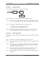
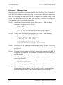
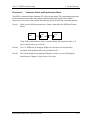
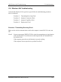
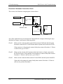
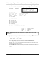
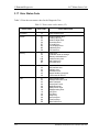
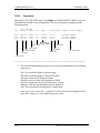
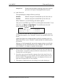
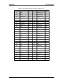
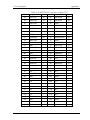
Debug Port Check on Boot Mode
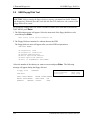
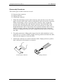
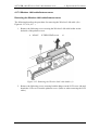
Check the D port status by a debug port test. The tool for debug port test is shown below.
Figure 2-3 A set of tool for debug port test
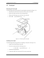
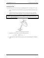
The test procedures are follows;
1. Connect the debug test cable to the connector PJ325 of the System board. For
disassembling to connect the test cable, refer to Chapter 4.
2. Connect the debug port test cable and RS-232C cross-cable to the test board.
3. Connect the RS-232C cross-cable to the PC that displays the results.
RS232C cross-cable
PC that displays
the test results
Debug port test cable
Test board
PJ325 System board
4. Boot the computer in MS-DOS mode.
PORTEGE R100 Maintenance Manual (960-440)
2-19
2 Troubleshooting
2.4 System board Troubleshooting
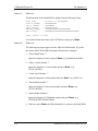
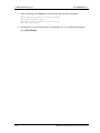
5. Execute GETDPORT.COM in the text menu in CPU REAL mode. (Insert the FD for
starting D port into FDD and input “FD starting drive:>dport”.)
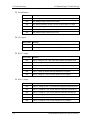
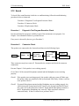
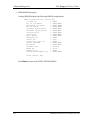
The D port status is displayed in the following form;
F100 : 000.000382
D port
status
Time (second) to
process
IRT_CHK_INI\SYSI_START
Contents of process
6. When the D port status is FFFFh (normal status), go to Procedure 3
7. When the D port status falls into any status in Table 2-3, execute Check 1.
2-20
PPORTEGE R100 Maintenance Manual (960-440)
2.4 System board Troubleshooting
2 Troubleshooting
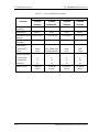
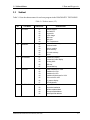
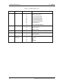
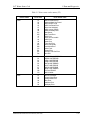
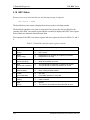
Table 2-3 D port status (1/6)
D port
status
Inspection items
details
F000h
Start
Clearing a software reset bit
Enabling address line A20
Initializing special registers and Intel chipset
Initializing the CH0 of a PIT
Initializing flags determining whether BIOS is rewritten
CHECK SUM CHECK
CHECK SUM CHECK
Switching to protected mode
Examining the checksum of Boot Block
Examining the checksum of other data in a flash memory
F001h
Initializing a KBC (1)
Checking if EC/KBC firmware is to be rewritten
Initializing a KBC
Sending command bytes
Sending scan enable command
Checking F12 key-in
F002h
Checking F12 key-in
Initializing a security controller
F005h
Checking whether BIOS
rewrite is requested
Checking whether BIOS rewrite is requested
F006H
Checking BIOS signature
Checking BIOS signature
F007h
Rewriting BIOS
Initializing HW
Initializing GPIO I/O space
Enabling BIOS writing
Serial interrupt control
Disabling BIOS write protection
Enabling SMBus I/O space
Enabling SMBus access
Configuring DRAM
Enabling L1 cache memory
Clearing memory
Disabling cache
Initializing special registers
F008h
Changing ROM BIOS to RAM BIOS
F009h
Storing key scan code
Setting up TASK_1ms_TSC
Displaying message on navipanel (EC/KBC UPDATE,
BIOS UPDATA/DAMAGED)
PORTEGE R100 Maintenance Manual (960-440)
2-21
2 Troubleshooting
2.4 System board Troubleshooting
Table 2-3 D port status (2/6)
D port status
Inspection items
details
Key inputting
Executing CHGBIOSA
Loading CHGBIOSA.EXE and CHGFIRMA.EXE
Resetting FDC
Setting parameter for 2HD and transmission rate
Reading the first sector
Setting parameter for 2DD and transmission rate
Searching CHGBIOSA.EXE in the root director
F009h
Calculating head and sector to start
Reading contents of root directory by one sector
Searching “CHGBIOSA.EXE”/ “CHGFIRMA.EXE” entry in
the sector
Reading EXE header of “CHGBIOSA.EXE”/
“CHGFIRMA.EXE”
Executing CHGBIOSA.EXE and CHGFIRMA.EXE
F100h
F101h
Initializing the Ch1 of a PIT(Refresh interval 30μs)
Checking the size and type of
DRAM
Testing the stack area of
SMRAM
F102h
Checking and initializing
CMOS
Checking the size and type of DRAM( on Cold Booting)
Checking the size of DRAM
Testing the stack area of SMRAM
Configuring cache memory
Enabling L1 cache memory
Testing CMOS for access ( on Cold Booting)
Checking the voltage of a CMOS backup battery
Examining the checksum of CMOS
Initializing data in CMOS (1)
Setting up IRT status
Storing the size of DRAM
F103h
Checking for branch of
resuming
Copying the contents of ROM
to RAM
Checking for branch of resuming
ICH4-M Power Failure
Examining the checksum of SMRAM
Checking whether the memory configuration have been
changed
Examining the checksum of system BIOS RAM area
Conducting resuming
Disabling all SMIs
2-22
PPORTEGE R100 Maintenance Manual (960-440)
2.4 System board Troubleshooting
2 Troubleshooting
Table 2-3 D port status (3/6)
D port status
Inspection items
F103
details
Clearing resuming status
Setting a request for a resuming error
Copying system BIOS from ROM to RAM
F104h
Initializing SMRAM
Initializing SMRAM
Checking the factor of WakeUp
Changing SMRAM base
Enabling SMI
F106h
Initializing a PIT and a CPU
Initializing devices before initializing PCI bus
Testing(only on COLD booting) and Initializing PIT
Setting test pattern to channel 0 of PIT#0
Checking whether the test pattern ca be read
Initializing PIT channel 0 (Interval of time
interrupt 55ms)
Initializing PIT channel 2 (frequency for sound
generator 664ms)
Testing PIT channel 1(Checks whether the refresh signal
operates correctly in refresh interval of 30μs)
Initializing PIT channel 2 ( checks whether the speaker
gate operates correctly)
Measuring CPU clock
Enabling SMI other than auto-off function
Control of battery discharging current
Performing timeshared process for time measurement of
IRT
Initializing CPU
Updating P6 micro-code
Enabling or disabling the function of processor serial
number ID
Checking whether Geyserville is supported
Switching CPU clock speed to high
Setting Graphics Aperture Size
F107h
Initializing ACPI, KBC, VGA,
Storing the size of ROM in a buffer
sound function, and PIC
Reading EC version
Updating the type of flash memory
Determining the destination
Checking the default settings of CMOS
Initializing ACPI table
PORTEGE R100 Maintenance Manual (960-440)
2-23
2 Troubleshooting
2.4 System board Troubleshooting
Table 2-3 D port status (4/6)
D port
status
Inspection items
F107h
details
Initializing devices before initializing PCI bus
Initializing temperature control information
Setting up a clock generator
AC’97 control
Initializing HC and recognizing devices
Initializing a KBC
Turning VGA display off and controlling reset
Initializing sound function
Starting the computer multiple box status check
Initializing a PCI
Testing a PIC
Initializing password
F108h
Starting sequence of HDD initializing
Initializing PCI
Initializing PCI bus
Checking the factor of WakeUp
F109h
Running a task waiting for the end of INIT_PCI
Initializing the data in CMOS (2)
Setting up the setup parameters
Setting Power off enable
Clearing wake-up conditions
CPU speed control
Control of panel open/close
Serial interrupt control
Serial interrupt control ( before using interrupts)
Initializing PC Card Slots
Auto-configuration of PCI
Creating a work area for auto configuration
Configuration
Storing the results of VGA configuration
F10Bh
Running a task waiting for completion of
PCI_CONFIGURATION
Initializing H/W required after
PCI configuration
Enabling/Disabling IEEE1394
Generating output codes
F10Ch
Checking the first 64KB of
memory
Checking the first 64KB of memory
F10D
Initializing interrupt vectors
Initializing interrupt vectors
2-24
PPORTEGE R100 Maintenance Manual (960-440)
2.4 System board Troubleshooting
2 Troubleshooting
Table 2-3 D port status (5/6)
D port status
Inspection items
Details
F10Eh
Initializing a NDP
Initializing a NDP
F10Fh
Setting up system
Storing CMOS error information in SMRAM
Initializing timer
Initializing a buffer for power saving
Initializing an EC, and reading battery information
Updating system BIOS (model name, and EDID of the
LCD)
F110h
Initializing the display
Waiting for completion of initializing VGA chip and
initializing VGA BIOS
F111h
Displaying a logo
Displaying a logo on the screen
F112h
Checking conventional memory
Checking conventional memory
F113h
Checking exception in protect
mode
Checking exception in protect mode
F114h
Checking DMA Page Register
Checking DMA Page Register
F117h
Checking DMAC
Checking DMAC
F118h
Initializing DMAC
Initializing DMAC
F119h
Checking password
Waiting for the end of the FDD initialization process
Waiting for the end of the HDD initialization
Checking key-in pressed during the IRT
Prioritizing ATA
F11Ch
Checking optional I/O ROM
Checking optional I/O ROM
F11Dh
Final setting up prior to boot-up
Storing the value of 40;00
Setting up the address of font data for resuming
password
Setting up the parameters for character repeat on a USB
keyboard
Getting keys pressed during the IRT
Storing shadow RAM size
Updating system resources information prior to boot-up
Renewing memory mapping data for INT15h E820h
function
Updating a table for DMI
Copying an ACPI table to the top of an expansion
memory
Waiting for the end of writing PSC version on BIOS
Waiting for the end of serial port initialization
PORTEGE R100 Maintenance Manual (960-440)
2-25
2 Troubleshooting
2.4 System board Troubleshooting
Table 2-3 D port status (6/6)
D port status
Inspection items
details
F11Dh
Canceling NMI mask
Examining the checksum of TIT
Clearing IRT running flag for runtime
Update checksum for runtime
Checking whether a CPU, an HDD or other component
have been upgraded
Disabling a PC Card that is not being used
Initializing HW just before
BOOT and waiting for the
completion
Setting up battery safe mode
Setting up date
Waiting for the end of AC-Link initialization
Updating DMI Wakeup factor and SM-BIOS structure
table
Closing configuration space of PCI devices
Cache control
Treating CPU-related items
Updating parameter block A
Setting up the clock speed of the CPU to the appointed
value by the Setup
Waiting for the motor off of a disabled HDD
FFFFh
Treating after
PRE_BOOT_SETUP
Clearing power button status
Completion
Completion of checking DPORT status
Enabling the power button
Check 1
If the D port status error code F11Ah is displayed, go to the 3.5” USB FDD
Troubleshooting Procedures in Section 2.5 or the 1.8” HDD Troubleshooting
Procedures in Section 2.6.
Check 2
If any other D port status error code is displayed, perform Procedure 3.
D port error statuses are following:
Error code
2-26
Contents
F160h
Timer CH2 error
F161h
PIT error
F162h
PIC #1 error
F163h
PIC #2 error
F11Eh
Clock generator setting error
PPORTEGE R100 Maintenance Manual (960-440)
2.4 System board Troubleshooting
Procedure 3
2 Troubleshooting
Diagnostic Test Program Execution Check
Execute the following tests from the Diagnostic Test Menu. These tests check the System
board and I/O unit. Refer to Chapter 3, Tests and Diagnostic, for more information on how to
perform these tests.
1. System test
2. Memory test
3. Keyboard test
4. Display test
5. Floppy Disk test
6. ASYNC test
7. Hard Disk test
8. Real Timer test
9. NDP test
10. Expansion test
11. Sound/LAN/Modem test
If an error is detected during these tests, go to Procedure 4.
Procedure 4
Replacement Check
I/O units or System board may be damaged. Replace the I/O units or disassemble the
computer following the steps described in Chapter 4 and replace the System board with a new
one.
PORTEGE R100 Maintenance Manual (960-440)
2-27
2 Troubleshooting
2.5 USB 3.5” FDD Troubleshooting
2
2.5
USB 3.5” FDD Troubleshooting
This section describes how to determine if the USB 3.5” FDD is functioning properly.
Perform the steps below starting with Procedure 1 and continuing with the other procedures as
required.
Procedure 1: FDD Head Cleaning Check
Procedure 2: Diagnostic Test Program Execution Check
Procedure 3: Connector Check and Replacement Check
Procedure 1
FDD Head Cleaning Check
FDD head cleaning is one option available in the Diagnostic Program.
Insert the Diagnostics Disk in the floppy disk drive of the computer, turn on the computer and
run the test. And then clean the FDD heads using the cleaning kit. If the FDD still does not
function properly after cleaning, go to Procedure 2.
Detailed operation is given in Chapter 3, Tests and Diagnostics.
If the test program cannot be executed on the computer, go to Procedure 3.
2-28
PORTEGE R100 Maintenance Manual (960-440)
2.5 USB 3.5” FDD Troubleshooting
Procedure 2
2 Troubleshooting
Diagnostic Test Program Execution Check
Insert the Diagnostics Disk in the FDD of the computer, turn on the computer and run the test.
Refer to Chapter 3, Tests and Diagnostics, for more information about the diagnostics test
procedures.
Make sure the floppy disk is formatted correctly and that the write protect tab is disabled.
Floppy disk drive test error codes and their status names are listed in Table 2-4. If any other
errors occur while executing the FDD diagnostics test, go to Check 1.
Table 2-4 FDD error code and status
Code
Check 1
Status
01h
Bad command
02h
Address mark not found
03h
Write protected
04h
Record not found
06h
Media replaced
08h
DMA overrun error
09h
DMA boundary error
10h
CRC error
20h
FDC error
40h
Seek error
60h
FDD not drive
80h
Time out error (Not ready)
EEh
Write buffer error
FFh
Data compare error
If the following message is displayed, disable the write protect tab on the floppy
disk by sliding the write protect tab to “write enable”. If any other message appears,
perform Check 2.
Write protected
Check 2
Make sure the floppy disk is formatted correctly. If it is, go to Procedure 3.
PORTEGE R100 Maintenance Manual (960-440)
2-29
2 Troubleshooting
Procedure 3
2.5 USB 3.5” FDD Troubleshooting
Connector Check and Replacement Check
The USB FDD connector may be disconnected from the System board. Check visually that the
connector is connected firmly.
Check 1
Make sure the following cable and connector are firmly connected to the connector
PJ4 (USB1) on the System board.
システム基
System
board
USB FDD
PJ4
If any of the connections are loose, reconnect firmly and repeat Procedure 2. If
there is still an error, go to Check 2.
Check 2
The USB FDD may be defective or damaged. Replace it with a new one. If the
FDD is still not functioning properly, perform Check 3.
Check 3
Replace the System board with a new one following the steps in Chapter 4,
Replacement Procedures.
2-30
PORTEGE R100 Maintenance Manual (960-440)
2.6 1.8” HDD Troubleshooting
2.6
2 Troubleshooting
1.8” HDD Troubleshooting
This section describes how to determine if the 1.8” HDD is functioning properly. Perform the
steps below starting with Procedure 1 and continuing with the other procedures as required.
Procedure 1: Partition Check
Procedure 2: Message Check
Procedure 3: Format Check
Procedure 4: Diagnostic Test Program Execution Check
Procedure 5: Connector Check and Replacement Check
CAUTION: The contents of the 1.8” hard disk will be erased when the 1.8” HDD
troubleshooting procedures are executed. Transfer the contents of the hard disk to floppy
disks or other storage drive(s). For the backup, refer to the User’s Manual.
Procedure 1
Partition Check
Insert the Toshiba MS-DOS system disk and start the computer. Perform the following
checks:
Check 1
Type C: and press [Enter]. If you cannot change to drive C, go to Check 2. If you
can change to drive C, go to Procedure 2.
Check 2
Type FDISK and press [Enter]. Choose Display Partition Information from the
FDISK menu. If drive C is listed in the Display Partition Information, go to Check
3. If drive C is not listed, return to the FDISK menu and choose the option to
create a DOS partition or a logical DOS drive on drive C. If the problem still exists,
go to Procedure 2.
Check 3
If drive C is listed as active in the FDISK menu, go to Check 4. If drive C is not
listed as active, return to the FDISK menu and choose the option to set the active
partition for drive C. Then go to Procedure 2.
Check 4
Remove the system disk from the FDD and reboot the computer. If the problem
still exists, go to Procedure 2. Otherwise, the HDD is operating normally.
PORTEGE R100 Maintenance Manual (960-440)
2-31
2 Troubleshooting
Procedure 2
2.6 1.8” HDD Troubleshooting
Message Check
When the power is turned on, the system performs the Initial Reliability Test (IRT) installed
in the BIOS ROM. When the test detects an error, an error message is displayed on the screen.
Make sure of no floppy disk in the FDD. Turn on the computer and check the message on the
screen. When an OS starts from the 1.8” HDD, go to Procedure 3. Otherwise, start with Check
1 below and perform the other checks as instructed.
Check 1
If any of the following messages appear, go to Procedure 3. If the following
messages do not appear, perform Check 2.
HDC ERROR
or
HDD #X ERROR (After 5 seconds this message will disappear.)
Check 2
If either of the following messages appears, go to Check 3. If the following
messages do not appear, perform Check 5.
Insert system disk in drive
Press any key when ready .....
or
Non-System disk or disk error
Replace and press any key when ready
Check 3
Check SETUP to see whether the Hard Disk option is set to Not used. If it is set to
Not used, choose another setting and return to Check 1. If it is not set to Not used,
go to Check 4.
Check 4
Using the SYS command of the MS-DOS, transfer the system to the 1.8" HDD. If
the system is not transferred, go to Procedure 3. Refer to the MS-DOS Manual for
detailed operation.
If the following message appears on the display, the system program has been
transferred to the HDD.
System Transferred
If an error message appears on the display, perform Check 5.
Check 5
2-32
The 1.8" HDD and the connector of the System board may be disconnected (Refer
to the steps described in Chapter 4, Replacement Procedures for disassembling.).
Insert the connectors firmly. If they are firmly connected, go to Procedure 3.
PORTEGE R100 Maintenance Manual (960-440)
2.6 1.8” HDD Troubleshooting
Procedure 3
2 Troubleshooting
Format Check
The computer’s 1.8" HDD is formatted using the MS-DOS FORMAT program or the physical
format program of the test program. To format the 1.8" HDD, start with Check 1 below and
perform the other steps as required.
Refer to the MS-DOS Manual for the operation of MS-DOS. For the format by the test
program, refer to the Chapter 3.
Check 1
Format the 1.8" HDD using MS-DOS FORMAT command. Type as FORMAT
C:/S/U.
If the 1.8" HDD can not be formatted, perform Check 2.
Check 2
Using the MS-DOS FDISK command, set the 1.8" HDD partition. If the partition
is not set, go to Check 3. If it is set, format the 1.8" HDD using MS-DOS
FORMAT command.
Check 3
Using the Diagnostic Disk, format the 1.8" HDD with a format option (physical
format). If the 1.8" HDD is formatted, set the 1.8" HDD partition using MS-DOS
FDISK command.
If you cannot format the 1.8" HDD using the Tests and Diagnostic program, go to
Procedure 4.
PORTEGE R100 Maintenance Manual (960-440)
2-33
2 Troubleshooting
Procedure 4
2.6 1.8” HDD Troubleshooting
Diagnostic Test Program Execution Check
The HDD test program is stored in the Diagnostics Disk. Perform all of the HDD tests in the
Hard Disk Drive Test. Refer to Chapter 3, Tests and Diagnostics, for more information about
the HDD test program.
If an error is detected during the HDD test, an error code and status will be displayed. The
error codes and statuses are described in Table 2-5. If an error code is not displayed but the
problem still exists, go to Procedure 5.
Table 2-5 1.8” HDD error code and status
Code
2-34
Status
01h
Bad command
02h
Address mark not found
04h
Record not found
05h
HDC not reset
07h
Drive not initialized
08h
HDC overrun error (DRQ)
09h
DMA boundary error
0Ah
Bad sector error
0Bh
Bad track error
10h
ECC error
11h
ECC recover enable
20h
HDC error
40h
Seek error
80h
Time out error
AAh
Drive not ready
BBh
Undefined error
CCh
Write fault
E0h
Status error
EEh
Access time out error
DAh
No HDD
PORTEGE R100 Maintenance Manual (960-440)
2.6 1.8” HDD Troubleshooting
Procedure 5
2 Troubleshooting
Connector Check and Replacement Check
The HDD is connected to the connector PJ3 of the System board. The connecting portion may
be disconnected. Disassemble the computer following the steps described in Chapter 4,
Replacement Procedures and perform the following checks to check the connecting portion:
Check 1
Make sure the following connector is firmly connected to the HDD and System
board.
HDD
HD
board
PJ1
PJ2
System
board
PJ3
If any of the connections are loose, reconnect firmly and repeat Procedure 1. If
there is still an error, go to Check 2.
Check 2
The 1.8" HDD may be damaged. Replace it with a new one and check the
operation. If the problem still exists, perform Check 3.
Check 3
The System board may be damaged. Replace it with a new one following the
instructions in Chapter 4, Replacement Procedures.
PORTEGE R100 Maintenance Manual (960-440)
2-35
2 Troubleshooting
2.7
2.7 Keyboard Troubleshooting
Keyboard Troubleshooting
To determine if the computer’s keyboard is functioning properly, perform the following
procedures. Start with Procedure 1 and continue with the other procedures as instructed.
Procedure 1: Diagnostic Test Program Execution Check
Procedure 2: Connector Check and Replacement Check
Procedure 1
Diagnostic Test Program Execution Check
Execute the Keyboard Test in the Diagnostic Program. Refer to Chapter 3, Tests and
Diagnostics for more information on how to perform the test program.
If an error occurs, go to Procedure 2. If an error does not occur, the keyboard is functioning
properly.
Procedure 2
Connector Check and Replacement Check
The keyboard or System board may be disconnected or damaged. Disassemble the computer
following the steps described in Chapter 4, Replacement Procedures and perform the
following checks:
Check 1
Make sure the keyboard cable is firmly connected to the System board.
System
Keyboard
PJ445
If the connection is loose, reconnect firmly and repeat Procedure 1. If there is still
an error, go to Check 2.
Check 2
The keyboard may be damaged. Replace it with a new one following the
instructions in Chapter 4, Replacement Procedures. If the problem still exists,
perform Check 3.
Check 3
The System board may be damaged. Replace it with a new one following the
instructions in Chapter 4, Replacement Procedures.
2-36
PORTEGE R100 Maintenance Manual (960-440)
2.8 Display Troubleshooting
2.8
2 Troubleshooting
Display Troubleshooting
This section describes how to determine if the computer’s display is functioning properly.
Start with Procedure 1 and continue with the other procedures as instructed.
Procedure 1: Diagnostic Test Program Execution Check
Procedure 2: Connector and Cable Check
Procedure 3: Fuse Conduction Check
Procedure 4: Replacement Check
Procedure 1
Diagnostic Test Program Execution Check
The Display Test program is stored on the Diagnostics disk. Insert the Diagnostics disk in the
computer’s floppy disk drive, turn on the computer and run the test. Refer to Chapter 3, Tests
and Diagnostics for details.
This program checks the display controller on the System board. If an error is detected, go to
Procedure 3.
Procedure 2
Connector and Cable Check
The LCD module is connected to the System board through the LCD harness. The cable may
be disconnected from each board or damaged. Disassemble the computer following the steps
described in Chapter 4, Replacement Procedures. If the connection is loose, reconnect firmly
and repeat Procedure 2. If there is still an error, go to Procedure 3.
Procedure 3
Fuse Conduction check
Some fuses may be blown. To test the conduction of the fuse F5600 and F56001 near the I/F
connector (PJ5600/PJ5601), disassemble the computer following the steps described in
Chapter 4, Replacement Procedures. If either fuse is blown, replace the system board repeat
Procedure 3. If there is still an error, go to Procedure 4.
PORTEGE R100 Maintenance Manual (960-440)
2-37
2 Troubleshooting
Procedure 4
2.8 Display Troubleshooting
Replacement Check
The display unit has a FL inverter board, Display module, System board, LCD harness and
Display ON/OFF switch. Any of the components may be damaged. Disassemble the computer
following the steps described in Chapter 4, Replacement Procedures, then perform the
following checks:
(1)
If characters or graphics are not displayed on the internal display, perform Check 1.
(2)
If characters are displayed on the internal display but the display is not normal,
perform Check 2.
(3)
If characters are displayed on the internal display but the display is dark (the back-light
does not light), perform Check 5.
Check 1
The display ON/OFF switch may be damaged. Remove the display ON/OFF
switch and repeat Procedure 4. If there is still an error, go to Check 2.
Check 2
The LCD harness may be damaged. Replace the damaged harness with a new one
and repeat Procedure 4. If there is still an error, go to Check 3.
Check 3
The display module may be damaged. Replace it with a new one and repeat
Procedure 4. If there is still an error, go to Check 4.
Check 4
The FL inverter board may be damaged. Replace it with a new one and repeat
Procedure 4. If there is still an error, go to Check 5.
Check 5
The FL may be damaged. Replace it with a new one and repeat Procedure 4. If
there is still an error, go to Check 6.
Check 6
The display controller of the System board may be damaged. Replace the System
board with a new one.
2-38
PORTEGE R100 Maintenance Manual (960-440)
2.9 Touch Pad
2.9
2 Troubleshooting
Touch Pad
To determine whether the Touch Pad is faulty or not, perform the following procedures:
Procedure 1 Diagnostic Test Program Execution Check
Procedure 2 Connector checking and replacement checking
Procedure 3: Replacement Check
Procedure 1 Diagnostic Test Program Execution Check
Execute the keyboard test program, or maintenance test program, because the pointing device
test program is a component of the keyboard test program. For the operating procedure, see
Chapter 3.
If any error is detected, perform Procedure 2. The pointing device is operating normally if no
error is detected.
Procedure 2 Connector checking and replacement checking
The touch pad is connected to the System board (PJ334) with a flexible cable. This cable may
have come off the connector or the connector may have come off the System board.
Disassemble the computer and check the cable connections. See Chapter 4 for the disassembly
procedure. If the connector has come off, connect firmly and make sure the operation. If there
is still an error, go to Procedure 3.
Touch Pad
Procedure 3
System board
PJ334
Replacement Check
The touch pad may be damaged. Replace the touch pad.
PORTEGE R100 Maintenance Manual (960-440)
2-39
2 Troubleshooting
2.10 Modem
2.10 Modem
To check if the modem is defective or malfunctioning, follow the troubleshooting procedures
below as instructed.
Procedure 1 Diagnostic Test Program Execution Check
Procedure 2 Connector Check and Replacement Check
Procedure 1
Diagnostic Test Program Execution Check
Execute the Modem test program available as part of the maintenance test program. This
program checks the modem. See Chapter 3 for information on how to perform the test.
If any error is detected by the test, go to Procedure 2.
2-40
PORTEGE R100 Maintenance Manual (960-440)
2.10 Modem
Procedure 2
2 Troubleshooting
Connector Check and Replacement Check
The Modem jack is connected to the MDC board and MDC board is connected to the System
board. If the modem malfunctions, these connections may be bad or the MDC or System
board might be faulty.
Disassemble the computer following the steps described in Chapter 4 and perform the
following checks:
Check 1
Make sure the MDC has been firmly connected to the PJ3 on the HD board. And
make sure the PJ1 on the HD board has been firmly connected to the PJ3 on the
System board
MDC
HD board
PJ3
PJ1
PJ3
System board
If any connector is disconnected, connect it firmly and return to Procedure 1. If
there is still an error, perform Check 2.
Check 2
The Modem jack may be faulty. Replace it with a new one. If the modem function
is still not working properly, perform Check 3.
Check 3
The MDC may be faulty. Replace it with a new one following the steps in Chapter
4. If the modem function is still not working properly, perform Check 4.
Check 4
The System board may be faulty. Replace it with a new one following the
instructions in Chapter 4.
PORTEGE R100 Maintenance Manual (960-440)
2-41
2 Troubleshooting
2.11 LAN
2.11 LAN
To check if the computer’s LAN is defective or malfunctioning, follow the troubleshooting
procedures below as instructed.
Procedure 1 Diagnostic Test Program Execution Check
Procedure 2 Connector Check and Replacement Check
Procedure 1
Diagnostic Test Program Execution Check
To check the LAN function, execute the Modem test program subtest 03 (LAN loop-back test).
See Chapter 3 for information on how to perform the test.
If any error is detected by the test, go to Procedure 2.
2-42
PORTEGE R100 Maintenance Manual (960-440)
2.11 LAN
2 Troubleshooting
Procedure 2
Connector Check and Replacement Check
The LAN function is installed on the System board. The modem/LAN jack is connected to the
System board by the cable. If the LAN malfunctions, the connection is bad or the System
board might be faulty.
Disassemble the computer following the steps described in Chapter 4 and perform the
following checks:
Check 1
Check if the LAN jack is connected firmly to the connector PJ352 of the System
board.
Network
PJ352
System board
If it is loose or disconnected, connect it firmly and return to Procedure 1. If there is
still an error, perform Check 2
Check 2
The LAN jack may be defective. Replace the LAN jack with a new one. If the
problem persist, perform Check 3.
Check 3
The System board may be faulty. Replace the System board following the steps
described in Chapter 4.
PORTEGE R100 Maintenance Manual (960-440)
2-43
2 Troubleshooting
2.12 Sound
2.12 Sound
To check if the sound function is defective or malfunctioning, follow the troubleshooting
procedures below as instructed.
Procedure 1 Diagnostic Test Program Execution Check
Procedure 2 Connector Check
Procedure 2 Replacement Check
Procedure 1
Diagnostic Test Program Execution Check
Execute the Sound test program available as part of the maintenance test program. See
Chapter 3 for information on how to perform the test.
If any error is detected by the test, go to Procedure 2
Procedure 2
Connector Check
The speakers are connected to the System board shown in the following figure.
Speaker
System board
PJ6002
PJ9
FL board
PJ500
PJ501
PJ997
Headphone
PJ998
External Microphone
SC board
PJ999
These connecters may have come off. Disassemble the computer and check the connector
connections.
Execute Chapter 1 if the speaker is not working properly.
Go to Check 2 if the external Microphone terminal and the Headphone are not working
properly.
Check 1 If the speaker is not working properly, the speaker cable may come off. Make sure
the speaker cables are connected to the System board PJ10 firmly. If there is still an
error, perform Check 3
Check 2 If external Microphone terminal and the Headphone are not working properly, the
cable between the System board and SC board, or the System board and FL board
may come off. Or the cable between the SC board and the Microphone terminal or
the SC board and the Headphone may come off. Make sure those cables are
connected firmly. If there is still an error, perform Check 3.
2-44
PORTEGE R100 Maintenance Manual (960-440)
2.12 Sound
Procedure 3
2 Troubleshooting
Replacement Check
Check 1
If the speaker is not working properly, the speaker may be faulty. Replace it with a
new one following the steps in Chapter 4. If the speaker is still not working
properly, go to Check 2.
Check 2
The System board may be faulty. Replace it with a new one following the
instructions in Chapter 4.
Check 3
The external Microphone terminal and the Headphone are not working properly,
the System board, the FL board or the SC board may be faulty. Replace those
boards with new ones following the steps in Chapter 4.
PORTEGE R100 Maintenance Manual (960-440)
2-45
2 Troubleshooting
2.13 SD card slot
2.13 SD card slot
To check if the SD card/Smart Media slot is good or no good, follow the troubleshooting
procedures below as instructed.
Procedure 1 Check on Windows
Procedure 2 Connector/Replacement Check
Procedure 1
Check on Windows
Insert a SD card into the slot. Check if the installed Windows XP recognizes automatically the
SD card and the data in the SD card can be read.
If the card is nor recognized or data are not read, go to Procedure 2.
Procedure 2
Connector/Replacement Check
The SD card is connected to the connector PJ364 of the System board.
SD card
P2210
System board
Check 1
Check the SD card is firmly inserted to the connector PJ2210 of the System board.
If not, insert it firmly. If the SD card is still not functioning properly, perform
Check 2.
Check 2
The SD card may be faulty. Replace it with a new one in order. If the problem
persists, perform Check 3.
Check 3
The System board may be faulty. Replace it with a new one.
2-46
PORTEGE R100 Maintenance Manual (960-440)
2.14 Wireless LAN Troubleshooting
2 Troubleshooting
2.14 Wireless LAN Troubleshooting
To check if the Wireless LAN is good or no good, follow the troubleshooting procedures
below as instructed.
Procedure 1: Transmitting-Receiving Check
Procedure 2: Antennas' Connection Check
Procedure 3: Antennas' Capability Check
Procedure 4: Replacement Check
Procedure 1 Transmitting-Receiving Check
Make sure the wireless communication switch on the computer is turned ON. If it is not, turn
ON.
Check 1
Execute test program CERT201T.EXE to check the transmitting-receiving function
of the wireless LAN. You will need a second computer that can communicate by
the wireless LAN
If the computer passes the test, the function is correctly working.
If the computer does not pass the test, perform Procedure 2.
PORTEGE R100 Maintenance Manual (960-440)
2-47
2 Troubleshooting
2.14 Wireless LAN Troubleshooting
Procedure 2 Antennas' Connection Check
The wireless LAN function wiring diagram is shown below:
MI board
Right Antenna
Wireless LAN
board
Left Antenna
Antenna Cable
PJ351
v
PJ1
SC board
(Switch)
PJ100
PJ9
PJ999
System board
Cable(FL board)
Any of the connections may be disconnected. Disassemble the computer following the steps
described in Chapter 4, perform the following checks:
Check 1
Make sure the connection between the Wireless board, MI board and the System
board (the connector PJ351 on MI board and the System board connector PJ100).
If the connecter is disconnected, connect firmly then return to Procedure 1. If there
is still an error, go to Check 2.
Check 2
Make sure the wireless LAN antennas (black and white) are firmly connected to
the Wireless board. If the antennas are disconnected, connect firmly then return to
Procedure 1. If there is still an error , go to Check 3.
Check 3
Make sure the connection between the SC board PJ999 and the System board PJ9.
If the cable is disconnected, connect firmly then return to Procedure 1. If there is
still an error, perform Procedure 3.
2-48
PORTEGE R100 Maintenance Manual (960-440)
2.14 Wireless LAN Troubleshooting
2 Troubleshooting
Procedure 3 Antenna Check
Use an antenna test cable to check the antennas' connection. Follow the steps below.
Any of the connections may be disconnected. Disassemble the computer following the steps
described in Chapter 4, perform the following checks
1. Disconnect the wireless LAN antenna (white and black) from the wireless LAN
board.
2. Connect the tester set up for impedance measurement to the antenna jig.
Measure the white antenna’s resistance
3. Determine the resistance. The antenna passes the test when the resistance is
less than 5Ω. If it is more than 5Ω, the antenna is faulty.
4. Measure the black antenna’s resistance. Check if there is faulty.
Figure 2-4 Antenna Test jig
Measurement Value
Pass/fail
Comment
Less than 5Ω
Pass
Include cable loss
More than 5Ω
Fail
The digital tester shows 0L ,etc. if there is a broken wire.
NOTE:
1.
The resistances determined with the steps above may not be stable according
to the length of the antenna. The impedance of the antenna itself is about 0.50.8Ω.
2.
The above steps cannot accurately determine the impedance of the antenna.
Use an LC meter for a precise measure of impedance.
If each wireless antenna pass the above test, return the Wireless LAN module back, then
perform Procedure 1.
If the wireless LAN has still an error, go to Procedure 4.
PORTEGE R100 Maintenance Manual (960-440)
2-49
2 Troubleshooting
Procedure 4
2.14 Wireless LAN Troubleshooting
Replacement Check
Check if the wireless LAN board, MI board, SC board and the System board are connected
properly. Any of these components may be damaged. Disassemble the computer following the
steps described in Chapter 4 and replace the board with a new one.
Check 1
The wireless LAN board or the MI board may be defective or damaged.
Disassemble the computer following the steps described in Chapter 4 and replace
the board with a new one. If there is still an error go to Check 2.
Check 2
The SC board may be defective or damaged. Disassemble the computer following
the steps described in Chapter 4 and replace the board with a new one. If there is
still an error go to Check 3.
Check 3
The System board may be defective or damaged. Disassemble the computer
following the steps described in Chapter 4 and replace the board with a new one.
2-50
PORTEGE R100 Maintenance Manual (960-440)
Chapter 3
Tests and Diagnostics
3 Tests and Diagnostics
3
3-ii
PORTREGE R 100 Maintenance Manual (960-440)
3 Tests and Diagnostics
Chapter 3
Contents
3.1
The Diagnostic Test ................................................................................................... 3-1
3.2
Executing the Diagnostic Test ................................................................................... 3-3
3.3
Subtest ....................................................................................................................... 3-7
3.4
System Test................................................................................................................ 3-9
3.5
Memory Test............................................................................................................ 3-12
3.6
Keyboard Test.......................................................................................................... 3-14
3.7
Display Test ............................................................................................................. 3-17
3.8
USB Floppy Disk Test ............................................................................................. 3-20
3.9
Hard Disk Test ......................................................................................................... 3-22
3.10
Real Timer Test........................................................................................................ 3-25
3.11
NDP Test.................................................................................................................. 3-27
3.12
Expansion Test......................................................................................................... 3-28
3.13
Wireless LAN Test (Agere) ..................................................................................... 3-30
3.14
Wireless LAN Test (Atheros) ................................................................................. 3-35
3.15
3.15 Wireless LAN Test (Calexico)......................................................................... 3-38
3.16
Sound/LAN/Modem Test ........................................................................................ 3-39
3.17
Error Status Code..................................................................................................... 3-42
3.18
HDC Status .............................................................................................................. 3-44
3.19
FDD Cleaning .......................................................................................................... 3-46
3.20
3.19.1
Function Description .......................................................................... 3-46
3.19.2
Operations .......................................................................................... 3-46
Log Utilities ............................................................................................................. 3-47
3.20.1
Function Description .......................................................................... 3-47
3.20.2
Operations .......................................................................................... 3-48
PORTEGE R100 Maintenance Manual (960-440)
3-iii
3 Tests and Diagnostics
3.21
3.22
3.23
3.24
Running Test............................................................................................................ 3-49
3.21.1
Function Description .......................................................................... 3-49
3.21.2
Operations .......................................................................................... 3-49
Floppy Disk Drive Utilities...................................................................................... 3-51
3.22.1
Function Description .......................................................................... 3-51
3.22.2
Operations .......................................................................................... 3-52
System Configuration .............................................................................................. 3-57
3.23.1
Function Description .......................................................................... 3-57
3.23.2
Operations .......................................................................................... 3-58
SETUP ..................................................................................................................... 3-59
3.24.1
Function Description .......................................................................... 3-59
3.24.2
Accessing the SETUP Program.......................................................... 3-60
Tables
Table 3-1 Subtest names ...................................................................................................... 3-7
Table 3-2 Error status codes names.................................................................................... 3-42
Table 3-3 Hard disk controller status register contents...................................................... 3-44
Table 3-4 Error register contents........................................................................................ 3-45
3-iv
PORTREGE R 100 Maintenance Manual (960-440)
3.1 The Diagnostic Test
3
3 Tests and Diagnostics
Tests and Diagnostics
3.1
The Diagnostic Test
This chapter explains how to use the Diagnostic Test program to test the functions of the
computer’s hardware modules. They are grouped into the Service Program Modules and the
Test Program Modules and the Diagnostic Test consists of 10 programs.
NOTE: To start the diagnostics, follow these steps:
1. Check all cables for loose connections.
2. Exit any application and close Windows.
The DIAGNOSTIC MENU consists of the following 8 test programs.
DIAGNOSTIC TEST
HARD DISK FORMAT
HEAD CLEANING
LOG UTILITIES
RUNNING TEST
FDD UTILITIES
SYSTEM CONFIGURATION
SETUP
The DIAGNOSTIC TEST MENU contains the following 9 functional tests:
SYSTEM TEST
MEMORY TEST
KEYBOARD TEST
DISPLAY TEST
FLOPPY DISK TEST
HARD DISK TEST
REAL TIMER TEST
NDP TEST
EXPANSION TEST
PORTEGE R100 Maintenance Manual (960-440)
3-1
3 Tests and Diagnostics
3.1 The Diagnostic Test
You will need the following equipment to perform some of the Diagnostic test programs.
The Diagnostics Disk (all tests, 3 disks)
A formatted working disk (Floppy disk test)
A cleaning kit to clean the floppy disk drive heads (FDD Head Cleaning)
A PC card wraparound connector (Expansion test)
An external CRT monitor (Expansion test)
Headphone (Sound/LAN/Modem test)
A microphone (Sound/LAN/Modem test)
FAT-MODE inspection device (Sound/LAN/Modem test)
The following sections detail the tests of the DIAGNOSTIC TEST MENU. Refer to Sections
3.13 through 3.24 for detailed information on the remaining Service Program Module
functions.
3-2
PORTEGE R100 Maintenance Manual (960-440)
3.2 Executing the Diagnostic TestExecuting the Diagnostic Test
3.2
3 Tests and Diagnostics
Executing the Diagnostic Test
To start the DIAGNOSTIC PROGRAM, follow these steps:
1. Insert the test program disk (No.1) in the floppy disk drive.
2. Turn on the computer by pressing the F12 key and, select the FDD in the display for
selecting booting unit. Then press ENTER. The following menu will appear:
TOSHIBA personal computer XXXX DIAGNOSTICS
version X.XX (c) copyright TOSHIBA Corp. 20XX
DIAGNOSTICS MENU :
1
2
3
4
5
6
7
8
9
–
-
DIAGNOSTIC TEST
HARD DISK FORMAT
HEAD CLEANING
LOG UTILITIES
RUNNING TEST
FDD UTILITIES
SYSTEM CONFIGURATION
EXIT TO MS-DOS
NOTE: To exit the DIAGNOSTIC TEST MENU, press the [Esc] key. If a test program is
in progress, press[ Ctrl] + [Break] to exit the test program. If a test program is in
progress, press [Ctrl] + [C] to stop the test program.
PORTEGE R100 Maintenance Manual (960-440)
3-3
3 Tests and Diagnostics
3.2 Executing the Diagnostic Test
3. Set the highlight bar to 1, and press Enter. The following TEST MENU will appear:
TOSHIBA personal computer XXXX DIAGNOSTICS
Version X.XX (c) copyright TOSHIBA Corp. 20XX
DIAGNOSTIC TEST MENU :
1
2
3
4
5
6
7
8
9
10
11
12
13
14
88
99
–
–
–
-
SYSTEM TEST
MEMORY TEST
KEYBOARD TEST
DISPLAY TEST
FLOPPY DISK TEST
HARD DISK TEST
REAL TIMER TEST
NDP TEST
EXPANSION TEST
ERROR RETRY COUNT SET [FDD & HDD]
EXIT TO DIAGNOSTICS MENU
Functions 1 through 14 are the Diagnostic Tests. Function 88 sets the floppy disk
drive and hard disk drive error retry count (0-255).
Return to the Diagnostics Menu, set the highlight bar to Function 99 and press Enter.
3-4
PORTEGE R100 Maintenance Manual (960-440)
3.2 Executing the Diagnostic TestExecuting the Diagnostic Test
3 Tests and Diagnostics
4. Select the option you want to execute on the test menu and press Enter. When you
select 1- SYSTEM TEST, the following message will appear:
TEST NAME
XXXXXXX
SUB-TEST : XX
PASS COUNT: XXXXX
WRITE DATA: XX
ADDRESS : XXXXXX
XXXX DIAGNOSTIC TEST VX.XX
[Ctrl]+[Break] ; test end
[Ctrl]+[C]
; key stop
ERROR COUNT: XXXXX
READ DATA : XX
STATUS : XXX
SUB-TEST MENU :
01
02
03
04
05
06
07
08
09
99
–
-
ROM checksum
Fan ON/OFF
Geyserville
Quick charge
DMI read
DMI write
CPU Temperature
Exit to DIAGNOSTIC TEST MENU
NOTE: The menu displayed by your computer may be slightly different from the one
shown above.
5. Select the desired subtest number from the subtest menu and press Enter. The
following message will appear:
TEST LOOP : YES (or NO)
ERROR STOP : YES (or NO)
Use the right and left arrow keys to move the cursor to the desired option.
Selecting YES of TEST LOOP increases the pass counter by one, each time the test
cycle ends and restarts the test cycle.
Selecting NO of TEST LOOP returns the process to the subtest menu after the test is
complete.
PORTEGE R100 Maintenance Manual (960-440)
3-5
3 Tests and Diagnostics
3.2 Executing the Diagnostic Test
Use the up and down arrow keys to move the cursor to “ERROR STOP”.
Use the right and left arrow keys to move the cursor to the desired option and press
Enter.
Selecting YES of ERROR STOP stops the test program when an error is found and
displays the operation guide on the right side of the display screen as shown below:
ERROR STATUS NAME
[[ HALT OPERATION ]]
1: Test end
2: Continue
3: Retry
Press [1]
Press [2]
Press [3]
Terminates the test program and returns to the subtest menu.
Continues the test.
Restarts the test from the error.
Selecting NO of ERROR STOP keeps the test running even if an error is found.
When an error occurred, the error status is displayed and the error counter is
increased by one.
6. Table 3-1 in section 3.3 describes the function of each test on the subtest menu. Table
3-2 in section 3.17 describes the error codes and error status for each error.
3-6
PORTEGE R100 Maintenance Manual (960-440)
3.3 SubtestSubtest
3.3
3 Tests and Diagnostics
Subtest
Table 3-1 lists the subtest names for each test program in the DIAGNOSTIC TEST MENU.
Table 3-1 Subtest names (1/2)
No.
Test Name
Subtest No.
Subtest Name
1
SYSTEM
01
04
05
06
07
08
09
ROM checksum
Fan ON/OFF
Geyserville
Quick charge
DMI read
DMI write
CPU Temperature
2
MEMORY
01
02
03
04
05
06
Conventional memory
Protected mode
Memory module
Cache memory
L2 Cache memory
Stress
3
KEYBOARD
01
02
04
05
07
Pressed key display
Pressed key code display
Pointing Stick
USB test
Internet/Mail key
4
DISPLAY
01
02
03
04
05
06
07
VRAM read/write for VGA
Gradation for VGA
Gradation for LCD
Gradation & Mode test for VGA
All dot on/off for LCD
“H” pattern display
LCD Brightness
5
FLOPPY DISK
01
02
03
04
05
Sequential read
Sequential read/write
Random address/data
Write specified address
Read specified address
PORTEGE R100 Maintenance Manual (960-440)
3-7
3 Tests and Diagnostics
3.3 Subtest
Table 3-1 Subtest names (2/2)
No.
Test Name
Subtest No.
8
HARD DISK
01
02
03
04
06
07
09
10
Sequential read
Address uniqueness
Random address/data
Cross talk & peak shift
Write specified address
Read specified address
Sequential write
W-R-C specified address
9
REAL TIMER
01
02
03
Real time
Backup memory
Real time carry
10
NDP
01
NDP test
11
EXPANSION
01
03
PCMCIA wraparound
RGB monitor ID
SOUND/MO
DEM/LAN
01
02
Microphone recording & play
Sin wave
LAN
MODEM
03
04
3-8
Subtest Name
PORTEGE R100 Maintenance Manual (960-440)
3.4 System TestSystem Test
3.4
3 Tests and Diagnostics
System Test
To execute the System Test, select 1-SYSTEM TEST from the DIAGNOSTIC TEST
MENU, press Enter and follow the directions on the screen. The System test contains seven
subtests. Move the highlight bar to the subtest you want to execute and press Enter.
Subtest 01
ROM Checksum
This subtest executes a checksum test of the BIOS ROM (range: F0000h to
FFFFFh, 64KB) on the System Board.
Subtest 04
Fan On/Off
This subtest checks CPU fan operation using the on/off command. The
following message will appear when this subtest is executed. Make sure the
fan does not rotate and press Enter.
*** Test Fan Revolution 0000RPM Start
The following message will appear. Make sure the fan rotates at low speed
and press Enter.
*** Test Fan Revolution Low speed start
The following message will appear. Make sure the fan rotates at high speed
and press Enter.
*** Test Fan Revolution High speed start
Subtest 05
Gerserville
If the CPU supports Gerserville (SpeedStep), this Subtest checks that the CPU
operating clock speed can be changed.
Subtest 06
Quick charge
This subtest checks the status for the quick charge.
PORTEGE R100 Maintenance Manual (960-440)
3-9
3 Tests and Diagnostics
Subtest 07
3.4 System Test
DMI read
The information in the Flash-ROM is displayed in the following format.
Model Name
Version Number
Serial Number
Model Number
PCN/BND Number
UNID Number
:
:
:
:
:
:
DyanBook SS XX/XXXXXX
XXXXXXXXXXX
XXXXXXXXX
XXXXXX-XXXXX
XXXXXXXXXXXX/XXXXXXXXXXX
XXXXXXXXXXXXXXXXXXXXXXXXXXXXXXXX
Press [Enter] to EXIT
To exit this subtest and return to the SYSTEM test menu, press Enter.
Subtest 08
DMI write
The following messages appear in order. Input each information. (If you do
not replace the PCB, the DMI information should not be changed.)
1. “Enter Model Name ?”
Input the computer’s name and press Enter. (e.g. DynaBook Satellite)
2. “Enter Version Number ?”
Input the computer’s version number and press Enter. (e.g.
XP341C401A86)
3.
“Enter Serial Number ?”
Input the computer’s serial number and press Enter. (e.g. Z9012374)
4. “Enter Model Number ?”
Input the computer’s sales model number and press Enter. (e.g.
XP341C401A86)
5. “Enter Bundle Number ?”
Input the computer’s PCN/bundle number and press Enter. (e.g.
PCN0482TOZ01/S2A0281D990)
6. When you press Enter, the DMI information is written to the Flash-ROM.
3-10
PORTEGE R100 Maintenance Manual (960-440)
3.4 System TestSystem Test
Subtest 09
3 Tests and Diagnostics
CPU Temperature
This subtest displays the temperature of the CPU
When the subtest is executed, the following message is displayed.
CPU TEMP = XX deg C
PORTEGE R100 Maintenance Manual (960-440)
Throttling level = XXXXh
3-11
3 Tests and Diagnostics
3.5
3.5 Memory Test
Memory Test
To execute the Memory Test, select 2-MOMORY TEST from the DIAGNOSTIC TEST
MENU, press Enter and follow the directions on the screen. The Memory test contains six
subtests that test the memory module. Move the highlight bar to the subtest you want to
execute and press Enter.
Subtest 01
Conventional Memory
This subtest writes data to conventional memory (0 to 640 KB). Then reads
and compares the result with the original data. The test address is displayed
each 4 KB.
Subtest 02
Protected Mode
NOTE: The CONFIG.SYS file must be configured without extended memory manager
programs such as EMM386.EXE, EMM386.SYS or QEMM386.SYS. Also, the
HIMEM.SYS must be deleted from the CONFIG.SYS file.
This subtest writes constant data and address data then reads the new data and
compares the result with the original data.
Subtest 03
Memory module
This subtest writes constant data and address data in an expanded memory
module then reads the new data and compares the result with the original data.
Subtest 04
Cache Memory
To test the cache memory, a pass-through write-read comparison of ‘5A’ data
is run repeatedly to the test area (‘7000’:’Program’ size to ‘7000’:’7EEE’ (32
KB)) to check the hit-miss ratio (on/off status) for CPU cache memory.
Number of misses < Number of hits → OK
Number of misses ≥ Number of hits → NG
3-12
PORTEGE R100 Maintenance Manual (960-440)
3.5 Memory TestMemory Test
Subtest 05
3 Tests and Diagnostics
L2 Cache Memory
To test the L2 cache memory, a pass-through write-read comparison of ‘5A’
data is run repeatedly to the test area (‘7000’:’Program’ size to ‘7000’:’7FFF’
(32 KB)) to check the hit-miss ratio (on/off status) for L2 cache memory.
Number of misses < Number of hits → OK
Number of misses ≥ Number of hits → NG
Read/Write/ Compare data directly by G.A. operation for the TAG-RAM.
Subtest 06
Stress
This test prepares the write/read buffer (size:1b30h) and produce write date in
the write buffer. The write data is written in the area larger than 1 MB and
read into the read buffer then repeated to compare until maximum size.
Test data:
ffh, ffh, ffh, ffh, ffh
00h, 00h, 00h, 00h, 00h
ffh, ffh, ffh, 00h, ffh
00h, 00h, 00h, ffh, 00h
00h, ffh, ffh, ffh, ffh
00h, 00h, 00h, 00h, aah
These data are generated repeatedly by 1b30h size.
PORTEGE R100 Maintenance Manual (960-440)
3-13
3 Tests and Diagnostics
3.6
3.6 Keyboard Test
Keyboard Test
To execute the Keyboard Test, select 3-KEYBOARD TEST from the DIAGNOSTIC TEST
MENU, press Enter and follow the directions on the screen. The Keyboard test contains five
subtests that test the computer’s keyboard actions. Move the highlight bar to the subtest you
want to execute and press Enter.
Subtest 01
Pressed Key Display
When you execute this subtest, the keyboard layout is drawn on the display as
shown below. When any key is pressed, the corresponding key on the screen
changes to the key character that was pressed. Holding a key down enables
the auto-repeat function which causes the key’s display character to blink.
Press DEL + Enter to exit.
Subtest 02
Pressed Key Code Display
This test displays scan code, character code and key top of the pressed key.
3-14
PORTEGE R100 Maintenance Manual (960-440)
3.6 Keyboard TestKeyboard Test
Subtest 04
3 Tests and Diagnostics
Touch pad/IPS
This subtest checks the functions of the touch pad as shown below.
A) Direction of touch pad.
B) Touch pad switch function check.
This test reports the response of touch pad, and touch pad switch. When you
touch the touch pad and slide your finger towards the upper left, the
<DIRECTION> display changes according to the following illustration.
When a touch pad switch is pressed, the <BUTTON> displays appear on the
right side one by one.
The parameters appear on the center of the display. To exit the subtest, press
the IPS <BUTTONS> at the same time.
***** IPS TEST PROGRAM (Vx.xx) *****
<POINTING>
■■
■■■■
■■■■■■
■■■■■■
■■■■
■■
<PARAMETER>
STATUS:0008h
X-RATE:0000h
Y-RATE:0000h
<BUTTONS>
(2)
(1)
<<Press BUTTON1 + BUTTON2 THEN END>>
***** IPS TEST PROGRAM (Vx.xx) *****
<BUTTONS>
(1)
(2)
<<Press BUTTON1 + BUTTON2 THEN END>>
PORTEGE R100 Maintenance Manual (960-440)
3-15
3 Tests and Diagnostics
Subtest 05
3.6 Keyboard Test
USB test
This subtest checks USB. The USB TEST Module (ZD0003P01) and USB
Cable (ZD0003P02) must be connected to the computer.
The following message will appear. Select a port to be tested and press Enter.
Test port number select (1:Port0, 2:Port1) ?
If the test ends successfully, OK is displayed. If nothing is displayed, there
may be a problem with the USB port.
Check the connection of the wraparound connector and repeat the test.
Subtest 07
Internet/Mail key
This subtest checks moving of the Internet key and Mail key.
The following message will appear.
Press [Internet] key
Press [Mail] key
3-16
PORTEGE R100 Maintenance Manual (960-440)
3.7 Display TestDisplay Test
3.7
3 Tests and Diagnostics
Display Test
To execute the Display Test, select 4-DISPLAY TEST from the DIAGNOSTIC TEST
MENU, press Enter and follow the directions on the screen. The Display test contains seven
subtests that test the display in various modes. Move the highlight bar to the subtest you want
to execute and press Enter.
Subtest 01
VRAM Read/Write for VGA
This subtest writes the constant data (AAh and 55h) and the address data to
the video RAM (16MB). The data is read and compared to the original data.
Subtest 02
Gradation for VGA
This subtest displays four colors: red, green, blue and white from left to right
across the screen from black to maximum brightness. The display below
appears on the screen when this subtest is executed.
To exit this subtest and return to the DISPLAY TEST menu, press Enter.
Subtest 03
Gradation for LCD
This subtest displays bands of gradations for mixed colors, then for red, green,
and blue. Next, it displays eight solid colors full screen: red, semi-red, green,
semi-green, blue, semi-blue, white, and semi-white. Each color displays for
three seconds.
PORTEGE R100 Maintenance Manual (960-440)
3-17
3 Tests and Diagnostics
Subtest 04
3.7 Display Test
Gradation & Mode test for VGA
This subtest displays gradations for following modes. To change the mode,
press Enter.
[Mode
[Mode
[Mode
[Mode
[Mode
[Mode
[Mode
[Mode
12]
13]
3]
111
112
114
115
117
640*480 64K]
640*480 16M]
800*600 64K]
800*600 16M]
1024*768 64K]
The display below appears on the screen when this subtest
is executed.
(Display example: Mode 12)
To exit this subtest and return to the DISPLAY TEST menu, press Enter.
Subtest 05
All Dot On /Off for LCD
This subtest displays an all-white screen then an all-black screen. The display
changes automatically every three seconds.
3-18
PORTEGE R100 Maintenance Manual (960-440)
3.7 Display TestDisplay Test
Subtest 06
3 Tests and Diagnostics
“H” Pattern Display
This subtest displays a full screen of “H” patterns.
HHHHHHHHHHHHHHHHHHHHHHHHHHHHHHHHHHHHHHHHHHHHHHHHHH
HHHHHHHHHHHHHHHHHHHHHHHHHHHHHHHHHHHHHHHHHHHHHHHHHH
HHHHHHHHHHHHHHHHHHHHHHHHHHHHHHHHHHHHHHHHHHHHHHHHHH
HHHHHHHHHHHHHHHHHHHHHHHHHHHHHHHHHHHHHHHHHHHHHHHHHH
HHHHHHHHHHHHHHHHHHHHHHHHHHHHHHHHHHHHHHHHHHHHHHHHHH
HHHHHHHHHHHHHHHHHHHHHHHHHHHHHHHHHHHHHHHHHHHHHHHHHH
HHHHHHHHHHHHHHHHHHHHHHHHHHHHHHHHHHHHHHHHHHHHHHHHHH
HHHHHHHHHHHHHHHHHHHHHHHHHHHHHHHHHHHHHHHHHHHHHHHHHH
HHHHHHHHHHHHHHHHHHHHHHHHHHHHHHHHHHHHHHHHHHHHHHHHHH
HHHHHHHHHHHHHHHHHHHHHHHHHHHHHHHHHHHHHHHHHHHHHHHHHH
HHHHHHHHHHHHHHHHHHHHHHHHHHHHHHHHHHHHHHHHHHHHHHHHHH
HHHHHHHHHHHHHHHHHHHHHHHHHHHHHHHHHHHHHHHHHHHHHHHHHH
HHHHHHHHHHHHHHHHHHHHHHHHHHHHHHHHHHHHHHHHHHHHHHHHHH
HHHHHHHHHHHHHHHHHHHHHHHHHHHHHHHHHHHHHHHHHHHHHHHHHH
HHHHHHHHHHHHHHHHHHHHHHHHHHHHHHHHHHHHHHHHHHHHHHHHHH
To exit this subtest and return to the DISPLAY TEST menu, press Enter.
NOTE: The last row may not be completely filled. This condition does not indicate an
error.
Subtest 07
LCD Brightness
The LCD brightness changes in the following order:
Super-Bright → Bright → Semi-Bright→ Bright → Super-Bright
PORTEGE R100 Maintenance Manual (960-440)
3-19
3 Tests and Diagnostics
3.8
3.8 USB Floppy Disk Test
USB Floppy Disk Test
COUTION: Before running the floppy disk test, prepare a formatted work disk. Remove
the Diagnostics Disk and insert the work disk into the FDD. Otherwise, the contents of the
floppy disk will be erased.
To execute the Floppy Disk Test, select 5-FLOPPY DISK TEST from the DIAGNOSTIC
TEST MENU, press Enter.
1. The following message will appear. Select the start track of the floppy disk drive to be
tested then press Enter.
Test start track (Enter:0/dd:00-79)
2. The Floppy Disk test contains five subtests that test the FDD.
The floppy disk test menu will appear after you select FDD test parameters.
SUB-TEST MENU:
01-Sequential read
02-Sequential read/write
03-Random address/data
04-Write specified address
05-Read specified address
99-Exit to DIAGNOSTIC TEST MENU
Select the number of the subtest you want to execute and press Enter. The following
message will appear during the floppy disk test.
Floppy Disk
XXXXXXX
xxx DIAGNOSTIC TEST VX.XX
[Ctrl]+[Break]
;test end
[Ctrl]+[C]
;key stop
SUB-TEST
PASS COUNT:XXXXX
WRITE DATA:XXXXX
ADDRESS
:XXXXXX
3-20
ERROR COUNT:XXXXX
READ DATA :XX
STATUS
:XXX
PORTEGE R100 Maintenance Manual (960-440)
3.8 USB Floppy Disk TestUSB Floppy Disk Test
Subtest 01
3 Tests and Diagnostics
Sequential Read
This subtest performs a Cyclic Redundancy Check (CRC) that continuously
reads all the tracks (track: 0 to 39/0 to 79) on a floppy disk.
The start track is specified at the start of the FDD test. Refer to 2.in this
chapter.
Subtest 02
Sequential Read/Write
This subtest continuously writes data pattern B5ADADh to all the tracks
(track: 0 to 39/0 to 79) on a floppy disk. The data is then read and compared
to the original data.
Subtest 03
Random Address/Data
This subtest writes random data to random addresses on all tracks (track: 0 to
39/0 to 79) on a floppy disk. The data is then read and compared to the
original data.
Subtest 04
Write Specified Address
This subtest writes the data specified by an operator to a specified track, head,
and address.
Subtest 05
Read Specified Address
This subtest reads data from a track, head, and address specified by an
operator.
PORTEGE R100 Maintenance Manual (960-440)
3-21
3 Tests and Diagnostics
3.9
3.9 Hard Disk Test
Hard Disk Test
To execute the Hard Disk Test, select 8-HARD DISK TEST from the DIAGNOSTIC TEST
MENU, press Enter, and follow the directions on the screen. The hard disk test contains
eight subtests that test the hard disk drive functions.
COUTION: The contents of the hard disk will be erased when subtest 02, 03, 04, 06, 09
or 10 is executed. Before running the test, the customer should transfer the
contents of the hard disk to another one by executing BACKUP.EXE or
others.
The following messages will appear after selecting the hard disk test from the DIAGNOSTIC
TEST MENU.
1. Select the hard disk test drive number to be tested.
Test drive number select
(1:HDD#1,2:HDD#2,0:HDD1&2)
2. This message is used to select the retry operation when the hard disk controller
detects an error. Select yes or no.
HDC F/W error retry
(1:yes,2:no)
3. This message is used to select the error dump operation when a data compare error is
detected. Select yes or no.
Data compare error dump
3-22
(1:No,2:Yes)
PORTEGE R100 Maintenance Manual (960-440)
3.9 Hard Disk TestHard Disk Test
3 Tests and Diagnostics
4. This message is used to select whether or not the HDC status is displayed on the
screen. The HDC status is described in section 3.18. Select yes or no.
Detail status display
(1:No,2:Yes)
5. After setting is completed, select the number of the subtest and press Enter. The
following message will appear.
HDD DISK TEST IN PROGRESS
XXXXXXX
SUB-TEST :XX
PASS COUNT:XXXXX
WRITE DATA:XXXXX
ADDRESS
:XXXXXX
xxx DIAGNOSTIC TEST VX.XX
[Ctrl]+[Break]
; test end
[Ctrl]+[C]
; key stop
ERROR COUNT:XXXXX
READ DATA :XX
STATUS
:XXX
The first three digits of the ADDRESS indicate which cylinder is being tested, the
fourth digit indicates the head and the last two digits indicate the sector.
The first digit of the STATUS number indicates the drive number being tested and
the last two digits indicate the error status code as explained in Table 3-2.
Subtest 01
Sequential read
This subtest is a sequential reading of all the tracks on the HDD starting at
track 0 to maximum track. When all the tracks on the HDD have been read,
the test starts at the maximum track and reads the tracks on the HDD
sequentially back to track 0.
Subtest 02
Address uniqueness
This subtest writes unique address data to each sector of the HDD track-bytrack. The data written to each sector is then read and compared with the
original data. There are three ways the HDD can be read:
1.
2.
3.
Subtest 03
Forward sequential
Reverse sequential
Random
Random address/data
This subtest writes random data in a random length to random addresses. This
data is then read and compared to the original data.
PORTEGE R100 Maintenance Manual (960-440)
3-23
3 Tests and Diagnostics
Subtest 04
3.9 Hard Disk Test
Cross Talk & Peak Shift
This subtest writes eight types of worst pattern data (listed below) to a
cylinder, then reads the data while moving from cylinder to cylinder (to check
the data interference in the neighbor track) to compare. After the third pass, it
tests the motor-off function (HDD motor is turned off, stops for 20 minutes
and is turned on).
Worst pattern data
Subtest 06
Cylinder
‘B5ADAD’
0 cylinder
‘4A5252’
1 cylinder
‘EB6DB6’
2 cylinder
‘149249’
3 cylinder
’63B63B’
4 cylinder
‘9C49C4’
5 cylinder
‘2DB6DB’
6 cylinder
‘D24924’
7 cylinder
Write Specified Address
This subtest writes specified data to a specified cylinder and head on the
HDD.
Subtest 07
Read Specified Address
This subtest reads data which has been written to a specified cylinder and
head on the HDD.
Subtest 09
Sequential Write
This subtest writes specified 2-byte data to all of the cylinders on the HDD.
Subtest 10
W-R-C Specified Address
This subtest writes data to a specified cylinder and head on the HDD, then
reads the data and compares it to the original data.
3-24
PORTEGE R100 Maintenance Manual (960-440)
3.10 Real Timer TestReal Timer Test
3 Tests and Diagnostics
3.10 Real Timer Test
To execute the Real Timer Test, select 9-REAL TIMER TEST from the DIAGNOSTIC
TEST MENU, press Enter and follow the directions on the screen. The real timer test
contains three subtests. Move the highlight bar to the subtest you want to execute and press
Enter.
Subtest 01
Real Time
A new date and time can be input during this subtest. To execute the real time
subtest follow these steps:
Step 1: Select subtest 01 and the following message will appear:
Current date : XX-XX-XXXX
Current time : XX:XX:XX
Enter new date:
PRESS [ENTER] KEY TO EXIT TEST
Step 2: If the current date is not correct, input the correct date and press
Enter. The date is updated and the following prompt will appear:
Enter new time :
Step 3: If the current time is not correct, input the correct time in 24-hour
format and press Enter. The time is updated.
The date and the time are displayed alternately by pressing Enter. To exit,
press Ctrl + Break.
Subtest 02
Backup Memory
This subtest checks the following backup memories:
Writes 1-bit of “on” data (01h through 80h) to address 0Eh through 7Fh
Writes 1-bit of “off” data (FEh through 7Fh) to address 0Eh through 7Fh
Writes the data pattern AAh and 55h to the address 0Eh to 7Fh
Then the subtest reads and compares this data with the original data.
PORTEGE R100 Maintenance Manual (960-440)
3-25
3 Tests and Diagnostics
Subtest 03
3.10 Real Timer Test
Real Time Carry
CAUTION: When this subtest is executed, the current date and time are erased.
This subtest checks the real time clock increments. Make sure the date and
time are displayed in the following format and they move forward correctly.
Current date :
Current time :
12-31-1999
23:59:58
PRESS [Enter] KEY TO EXIT TEST
Press Enter to exit.
3-26
PORTEGE R100 Maintenance Manual (960-440)
3.11 NDP TestNDP Test
3 Tests and Diagnostics
3.11 NDP Test
To execute the NDP test, select 10-NDP TEST from the DIAGNOSTICS TEST MENU,
press Enter and follow the directions on the screen. The NDP test contains one subtest.
Subtest 01
NDP
This test checks the following functions of NDP:
Control word
Status word
Bus
Addition
Multiplication
Press Ctrl + Break to exit.
PORTEGE R100 Maintenance Manual (960-440)
3-27
3 Tests and Diagnostics
3.12 Expansion Test
3.12 Expansion Test
To execute the expansion test, select 11-EXPANSION TEST from the DIAGNOSTICS
TEST MENU, press Enter and follow the directions on the screen. The expansion test
contains two subtests.
NOTE: To execute this subtest, the PC card wraparound connector is required.
Subtest 01
PCMCIA Wraparound
This test checks the following signal line of the PC card slot:
Address line
REG#, CE#1, CE#2 line
Data line
Speaker line
Wait line
BSY#, BVD1 line
This subtest is executed in the following order:
Sub#
Address
Good
Bad
Contents
01
00001
00001
nn
nn
xx
xx
Address line
REG#, CE#1, CE#2
nn=A0, 90, 80, 00
02
00002
ww
rr
Data line
ww=write data, rr=read data
03
00003
––
––
Speaker line
04
00004
40,80
xx
Wait line (40<xx<80)
05
00005
nn
xx
Other lines (BSY#, BVD1)
NN=21, 00
NOTE: When selecting the subtest number 01, the following message will appear. Specify
the slot you want to use.
Test slot number select (1:slot0, 2:slot1, 0:slot0&1)?
Select the number.
3-28
PORTEGE R100 Maintenance Manual (960-440)
3.12 Expansion TestExpansion Test
Subtest 03
3 Tests and Diagnostics
RGB monitor ID test
Connect a CRT monitor for this subtest. This subtest is conducted with VESA
commands.
PORTEGE R100 Maintenance Manual (960-440)
3-29
3 Tests and Diagnostics
3
3.13 Wireless LAN Test (Agere)
Tests and Diagnostics
3.13 Wireless LAN Test (Agere)
This section describes how to perform the wireless LAN transmitting-receiving test with the
test program.
NOTE: Use another computer (with Agere wireless LAN card) that can
communicate by the wireless LAN as a reference machine to perform this test.
To start the Wireless LAN test program, follow the steps below:
NOTE: 1) Before starting the wireless LAN test, make sure the Wireless
Communication Switch on the left side of the computer is turned on. (The
Wireless Communication LED lights orange.)
2) Release the write-protection of the floppy disk for the test.
Insert a floppy disk containing the test program into the target machine and turn on the target
machine. The Wireless LAN test menu will appear.
##############################################################
####
Wireless LAN sub system repair test VX.XX
####
##############################################################
*
*
*
1 Transmit & Receive test [Responder]
*
*
2 MAC Address test [Mini-PCI Wireless LAN]
*
*
3 Wireless LAN (WEP64/128) test
*
*
*
*
0 Transmit & Receive test [Initiator]
*
*
*
*************************************************************
....Press test number [1-3,0]
?
Press 1, 2 or 3, and the Enter to perform the corresponding sub test. To quit the Wireless
LAN test program, eject the floppy disk and turn the computer off while the menu above is
displayed.
3-30
PORTEGE R100 Maintenance Manual (960-440)
3.13 Wireless LAN Test (Agere)
Subtest 01
3 Tests and Diagnostics
Transmit & Receive test
This sub test checks transmit and receive functions.
Transmit test
Press 1 to select the test and press Enter in the target machine as a responder. The following
message will appear:
###############################################################
####
Wireless LAN sub system repair test VX.XX
####
###############################################################
*
*
*
1 Transmit & Receive test [Responder]
*
*
2 MAC Address test [Mini-PCI Wireless LAN]
*
*
3 Wireless LAN (WEP64/128) test
*
*
*
*
0 Transmit & Receive test [Initiator]
*
*
*
***************************************************************
....Press test number [1-2,0]
?1
======== RESPONDER SET ========
ORiWL.EXE Rev.03 Copyright (c) Toshiba Corporation,2000, 2001
Initializing...
[[[ Responder Mode ]]]
MAC adress : XXXXXXXXXXXX
Ad-hoc mode
SS ID : PHN Test
Channel : 10
Tx ratio : 2 Mbps
To prepare the tester machine for the Wireless LAN test program, insert a floppy disk
containing the test program into the tester machine and turn on the tester machine. The
Wireless LAN test menu will appear.
Press 0 to select the test and press Enter in the initiator machine. The following message
will appear:
##############################################################
####
Wireless LAN sub system repair test VX.XX
####
##############################################################
*
*
*
1 Transmit & Receive test [Responder]
*
*
2 MAC Address test [Mini-PCI Wireless LAN]
*
*
*
*
0 Transmit & Receive test [Initiator]
*
*
*
*************************************************************
....Press test number [1-2,0]
?1
======== RESPONDER SET ========
ORiWL.EXE Rev.03 Copyright (c) Toshiba Corporation,2000, 2001
Initializing...
[[[ Responder Mode ]]]
MAC address : XXXXXXXXXXXX
Ad-hoc mode
SS ID : PHN Test
Channel : 10
Tx ratio : 2 Mbp
PASS : 134 ERROR : 0
PORTEGE R100 Maintenance Manual (960-440)
3-31
3 Tests and Diagnostics
3.13 Wireless LAN Test (Agere)
When the machine has passed the test, “OK” message will appear in the test machine.
Then press Enter in the target machine; the “OK” message will appear also in the target
machine.
Press Enter to return to the main menu.
Receive test
In receive test reverse the procedures of the transmit test. To prepare the tester machine for
the Wireless LAN test program, insert a floppy disk containing the test program into the
tester machine and turn on the tester machine. The Wireless LAN test menu will appear.
Press 1 to select the test and press Enter. The following message will appear:
##############################################################
####
Wireless LAN sub system repair test VX.XX
####
##############################################################
*
*
*
1 Transmit & Receive test [Responder]
*
*
2 MAC Address test [Mini-PCI Wireless LAN]
*
*
3 Wireless LAN (WEP64/128) test
*
*
*
*
0 Transmit & Receive test [Initiator]
*
*
*
*************************************************************
....Press test number [1-2,0]
?1
======== RESPONDER SET ========
ORiWL.EXE Rev.03 Copyright (c) Toshiba Corporation,2000, 2001
Initializing...
[[[ Responder Mode ]]]
MAC address : XXXXXXXXXXXX
Ad-hoc mode
SS ID : PHN Test
Channel : 10
Tx ratio : 2 Mbps
PASS : 134 ERROR : 0
3-32
PORTEGE R100 Maintenance Manual (960-440)
3.13 Wireless LAN Test (Agere)
3 Tests and Diagnostics
Press 0 to select the test and press Enter in the target machine. The following message will
appear:
##############################################################
####
Wireless LAN sub system repair test VX.XX
####
##############################################################
*
*
*
1 Transmit & Receive test [Responder]
*
*
2 MAC Address test [Mini-PCI Wireless LAN]
*
*
3 Wireless LAN (WEP64/128) test
*
*
*
*
0 Transmit & Receive test [Initiator]
*
*
*
*************************************************************
....Press test number [1-2,0]
?1
======== RESPONDER SET ========
ORiWL.EXE Rev.03 Copyright (c) Toshiba Corporation,2000, 2001
Initializing...
[[[ Responder Mode ]]]
MAC address : XXXXXXXXXXXX
Ad-hoc mode
SS ID : PHN Test
Channel : 10
Tx ratio : 2 Mbps
When the machine has passed the test, “OK” message will appear in the target machine.
Then press Enter in the test machine; the “OK” message will appear also in the test
machine.
Press Enter to return to the main menu.
PORTEGE R100 Maintenance Manual (960-440)
3-33
3 Tests and Diagnostics
Subtest 02
3.13 Wireless LAN Test (Agere)
Mac Address test
This subtest reads MAC Address. If there is no problem, the “OK” message
will appear.
Subtest 03
Wireless LAN (WEP64/128) test
This subtest reads the WEP of the wireless LAN card installed in the target
machine. A message similar to the following will appear:
****** This CARD is WEP ******
Press any key to continue
3-34
PORTEGE R100 Maintenance Manual (960-440)
3.14 Wireless LAN Test (Atheros)
3 Tests and Diagnostics
3.14 Wireless LAN Test (Atheros)
This section describes how to perform the wireless LAN transmitting-receiving test with the
test program.
NOTE: Use another computer (with Atheros wireless LAN card) that can
communicate by the wireless LAN as a responder machine to perform this test.
In this test, the following items are tested:
* Test PC [Initiator] side
(1) SKU (destination code) check
(2) Mac Address check
(3) Communication test (802.11a Main antenna)
(4) Communication test (802.11a Sub antenna)
(5) Communication test (802.11b)
* [Responder] side
(1) Communication test (802.11b)
This program conducts the above test items continuously and displays results for each item
during the test. However, only the last result for the whole test shall be checked. (The
message "OK" or "NG" is displayed.)
When an "NG" item is detected during the test, the message "NG" is displayed on the screen
and the test stops.
NOTE: This program takes a long time until the test ends.
To start the Wireless LAN test program, follow the steps below:
NOTE: Before starting the wireless LAN test, make sure the Wireless
Communication Switch on the left side of the computer is turned on. (The Wireless
Communication LED lights orange.)
PORTEGE R100 Maintenance Manual (960-440)
3-35
3 Tests and Diagnostics
3.14 Wireless LAN Test (Atheros)
Setting the responder machine
NOTE: Release the write-protection of the floppy disk for the test.
Insert a floppy disk containing the test program into the FDD for the responder machine and
turn on the responder machine. The Wireless LAN test menu will appear.
###############################################################
####
Atheros WLAN sub system repair test VX.XX
####
###############################################################
*
*
*
1 .....Test PC [Initiator]
*
*
*
*
0 .....[Responder]
*
*
*
***************************************************************
....Press test number [1,0] ?
Press 0 and Enter in the responder machine. After a while, the following messages will
appear. The latter message is updated ever 3 seconds.
Waiting for transmitter to ring the bell in 11a mode.
Input or output error (EIO) : rxDatBegin : nothing receive within
3000millisecs(waitTime)
The responder machine is ready for the test.
Setting the tester machine
NOTE: Release the write-protection of the floppy disk for the test.
Insert a floppy disk containing the test program into the FDD of the tester machine and turn
on the tester machine. The Wireless LAN test menu will appear.
###############################################################
####
Atheros WLAN sub system repair test VX.XX
####
###############################################################
*
*
*
1 .....Test PC [Initiator]
*
*
*
*
0 .....[Responder]
*
*
*
***************************************************************
....Press test number [1,0] ?
Press 1 and Enter in the tester machine. After a while, the following message will appear:
-------------------------------------------mac address check OK !!
...Press any key !!
--------------------------------------------
To proceed the test, press any key.
3-36
PORTEGE R100 Maintenance Manual (960-440)
3.14 Wireless LAN Test (Atheros)
3 Tests and Diagnostics
When the tester machine has passed the test, "OK" message will appear in the tester machine.
Press Enter to return to the main menu.
When the tester machine has not passed the test, "NG" message will appear in the tester
machine. Pressing Enter on the screen shows the following message.
*************************************************************
*
*
*
8.02 11a Tx Test AUX Antenna NG
*
*
*
*************************************************************
Then the test returns to the main menu automatically.
PORTEGE R100 Maintenance Manual (960-440)
3-37
3 Tests and Diagnostics
3.15 Wireless LAN Test (Calexico)
3.15 Wireless LAN Test (Calexico)
This section describes how to perform the wireless LAN transmitting-receiving test with the
test program.
NOTE: Use another computer (with Calexico wireless LAN card) that can communicate
by the wireless LAN as a reference machine to perform this test. An access point is also
required.
In this test, the following items are tested.
(1) Communication test (Main antenna, Aux antenna)
(2)
MAC address Check
To start the Wireless LAN test program, follow the steps below:
NOTE: Before starting the wireless LAN test, make sure the Wireless Communication
Switch on the left side of the computer is turned on. (The Wireless Communication LED
lights orange.) Release the write-protection of the floppy disk for the test.
Setting the responder machine
Connect the responder machine to the access point with a cross cable and turn on the access
point.
Insert the floppy disk containing the wireless LAN test program into the USB FDD of the
responder machine and turn on the responder machine. Then wait until the following
message appears.
Setting the target machine
Insert the floppy disk containing the wireless LAN test program into the USB FDD of the
target machine and turn on the target machine. Then the test starts automatically.
When the machine has passed the test, “OK !” message will appear on the target machine.
Press any key to exit the test.
When an error is detected during the test, “NG !” massage will appear. Press any key to
display the NG item (Main antenna, Aux. antenna or MAC address check). The following
message appears.
*************************************************************
*
*
*
Main Antenna Test: NG !!
*
*
*
*************************************************************
3-38
PORTEGE R100 Maintenance Manual (960-440)
3.16 Sound/LAN/Modem Test
3 Tests and Diagnostics
3.16 Sound/LAN/Modem Test
To execute the Sound/LAN/Modem Test, use the Test Diagnostics disk (No.2). Finish the
tests of the Diagnostics disk (No.1) by selecting 99 - EXIT TO DIAGNOSTICS MENU in
the DIAGNOSTIC TEST MENU. Then in the DIAGNOSTICS MENU, select 9 - EXIT TO
MS-DOS.
Insert the Test program disk (No.2) in the floppy disk drive and turn on the power. The
following message will appear:
####################################################################
#######
GUAM DIAGNOSTICS PROGRAM (SOUND/LAN/MODEM TEST)
#######
####################################################################
*
*
*
1 ............ (Microphoned recording&play)
*
*
2 ............ (Sin wave)
*
*
3 ............ (LAN)
*
*
4 ............ (MODEM)
*
********************************************************************
.... Press test number[1-4] ?
Press the number you want to test and press Enter.
Subtest 01
Microphoned recording & play
This subtest checks the function of the CODEC A/D D/A converter. Both the
microphone and headphone terminal can be checked at the same time.
Before executing this subtest, connect an external microphone to the
computer. If necessary, connect a headphone to the computer to check
whether the headphone jack of the computer is working properly.
When the subtest is selected, the following message appears.
....Press test number[1-4] ? pause
Press any key, and the following two messages appear.
Press any key to continue...
....Press test number[1-4] ? call micrec
The sound is recorded for five seconds automatically from the microphone.
After the recording is completed, the computer immediately plays back the
sound recorded. When the playing is finished, a message similar to the one
below appears.
PORTEGE R100 Maintenance Manual (960-440)
3-39
3 Tests and Diagnostics
Completing
End time
System Status
3.16 Sound/LAN/Modem Test
SoundMAX/ICH microphone capture test
XXX XXX XX XX*XX:XX XXXX
0x0
Performing SoundMAX/ICH play buffer to line out
Start Time:
XXX XXX XX XX:XX:XX XXXX
Play to destination is LINEOUT
Volume requested is X.XXX dB
Play from buffer name is BUFFER0
Requested play time is 5.000 seconds.
Actual play time will be 5.000 seconds.
Completing SoundMAX/ICH play buffer to line out
End Time XXX XXX XX :XX:XX XXXX
System Status 0x0
Test completed at XXX XXX XX :XX:XX XXXX
System completion code was 0x0
Then, the screen returns to the main menu and the following message will
appears.
....Press test number[1-4] ?
To execute a subtest continuously, select the test number and press Enter. To
exit the Sound/LAN/Modem test, remove the test program disk from the USB
FDD and turn off the computer.
Subtest 02
Sin Wave
This subtest is executed by the load format of COM file (ADSIN.COM). The
program expands sin wave data table to data in 16-64KB, and creates play
data (It sounds like continuous beep). By using wave measuring devices such
as an oscilloscope, this program can read sine wave without expanding.
When the subtest is executed, the following message appears.
....Press test number[1-4] ? pause
Press any key to continue...
Press any key, and the following message appears. Then sin wave is expanded
to 16-64KB data and is played.
....Press test number[1-4] ? call sin
When the beep sound finished, the screen returns to the main menu and the
following massage appears.
3-40
PORTEGE R100 Maintenance Manual (960-440)
3.16 Sound/LAN/Modem Test
3 Tests and Diagnostics
....Press test number [1-4] ?
To execute a subtest continuously, select the test number and press Enter. To
exit the Sound/Modem test, remove the test program disk from the USB FDD
and turn the computer off.
Subtest 03
LAN
This subtest checks the operation of mini-PCI I/F by the loopback in the chip.
The large “OK” is displayed if no error occurred.
Subtest 04
MODEM
For this subtest, connect the modem PCB and RJ11 connector with a harness.
This subtest contains the following tests. They are tested with the dedicated
“FAT-MODE inspection device(Product Code QE2000P01 made by Nittou
Denki Seisakusyo)
•
•
•
•
•
Scorpio Modem Initialize
Digital Loopback Test
Modem Sound Test
External Loopback test
RJ11 Connector Test (LED)
To finish the Sound/LAN/Modem test, the power of the computer is turned
off.
PORTEGE R100 Maintenance Manual (960-440)
3-41
3 Tests and Diagnostics
3.17 Error Status Code
3.17 Error Status Code
Table 3-2 lists the error status codes for the Diagnostic Test.
Table 3-2 Error status codes names (1/2)
Device name
3-42
Error code
Error status name
(Common)
FF
Data Compare Error
System
01
02
03
04
FE
0A
0B
88
ROM Checksum Error
Location ID Error
Serial ID Writer Error
Thermistor Error
EC read Error
LAN loopback Error
1394 date Error
FAN test Error
Memory
01
02
14
DD
DE
DF
Parity error
Protected mode not change
Memory write/read error
Cache memory error
2nd Cache error
TAG-RAM error
Keyboard
01
02
03
04
05
06
Mouse interface error
IPS interface error
Interface error
Retransmit error
Mouse handler not support
PS/2 mouse & IPS not
FDD
01
02
03
04
06
08
09
10
20
40
60
80
EE
Bad Command Error
Address Mark Not Found
Write Protected
Record Not Found
Media Removed
DMA Overrun Error
DMA Boundary Error
CRC Error
FDC Error
Seek Error
Not Drive Error
Time Out Error
Write Buffer Error
PORTEGE R100 Maintenance Manual (960-440)
3.17 Error Status Code
3 Tests and Diagnostics
Table 3-2 Error status codes names (2/2)
Device name
Error code
Error status name
HDD
01
02
04
05
07
08
09
0A
0B
10
11
20
40
80
AA
BB
CC
E0
EE
DA
Bad Command Error
Address Mark Not Found
Record Not Found
HDC Not Reset Error
Drive Not Initialized
HDC overrun (DRQ)
DMA Boundary Error
Bad Sector
Bad Track Error
ECC Error
ECC recover enable
HDC Error
Seek Error
Time Out Error
Drive Not Ready
Undefined Error
Write Fault
Status Error
Access Time Out Error
No HDD
PCMCIA
C1
C2
C3
C4
C5
C6
C7
C8
CB
CD
ADDRESS LINE ERROR
REG# LINE ERROR
CE#1 LINE ERROR
CE#2 LINE ERROR
DATA LINE ERROR
WAIT LINE ERROR
BSY# LINE ERROR
BVD1 LINE ERROR
ZV Port ERROR
NO PCMCIA
NDP
01
02
03
04
05
06
No Co-Processor
Control Word Error
Status Word Error
Bus Error
Addition Error
Multiplay Error
PORTEGE R100 Maintenance Manual (960-440)
3-43
3 Tests and Diagnostics
3.18 HDC Status
3.18 HDC Status
When an error occurs in the hard disk test, the following message is displayed:
HDC status = XXXX
The hard disk test error status is displayed on the screen by a four-digit number.
The hard disk controller error status is composed of two bytes; the first byte displays the
contents of the HDC error status register and the second byte displays the HDC error register.
Each of them are indicated in hexadecimal form
The contents of the HDC error status register and error register are listed in Tables 3-3 and 34.
Table 3-3 Hard disk controller status register contents
Bit
Name
Description
7
BSY
(Busy)
“0” … HDC is ready.
“1” … HDC is busy.
6
DRDY
(Drive ready)
“0” … Hard disk drive is not ready to accept any command.
“1” … Hard disk drive is ready.
5
DWF
(Drive write fault)
“0” … DWF error is not detected.
“1” … Write fault condition occurred.
4
DSC
(Drive seek complete)
“0” … The hard disk drive heads are not settled over a track.
“1” … The hard disk drive heads are settled over a track.
3
DRQ
(Data request)
“0” … Drive is not ready for data transfer.
“1” … Drive is ready for data transfer.
2
CORR
(Corrected data)
“0” … Not used
“1” … Correctable data error is corrected.
1
IDX
(Index)
“0” … Not used
“1” … Index is sensed.
0
ERR
(Error)
“0” … Normal
“1” … The previous command was terminated with an error.
3-44
PORTEGE R100 Maintenance Manual (960-440)
3.18 HDC Status
3 Tests and Diagnostics
Table 3-4 Error register contents
Bit
Name
Description
7
BBK
(Bad block mark)
“0” … Not used
“1” … A bad block mark is detected.
6
UNC
(Uncorrectable)
“0” … There is no uncorrectable data error.
“1” … Uncorrectable data error has been detected.
5
——
Not used
4
IDN
(Identification)
“0” … Not used
“1” … There was no ID field.
3
——
Not used
2
ABT
(Abort)
“0” … Not used
“1” … Illegal command error or a command abort.
1
TK0
(Track zero)
“0” … The hard disk detected track 0.
“1” … The hard disk could not detect track 0.
0
——
Not used.
PORTEGE R100 Maintenance Manual (960-440)
3-45
3 Tests and Diagnostics
3.19 FDD Cleaning
3.19 FDD Cleaning
3.19.1
Function Description
This function cleans the heads in the 3.5-inch FDD by executing a series of head load/seek
and read operations. A cleaning disk is necessary to perform this program.
3.19.2
Operations
1. Selecting test 4-HEAD CLEANING from the DIAGNOSTIC MENU and pressing
Enter displays the following messages:
DIAGNOSTICS – FLOPPY DISK HEAD CLEANING : V6.00
Mount cleaning disk(s) on drive(s).
Press any key when ready.
2. Remove the Diagnostics Disk from the FDD, then insert the cleaning disk and press
Enter.
3. When the following message appears, the FDD head cleaning has begun.
Cleaning start
4. The display automatically returns to the DIAGNOSTIC MENU when the program is
completed.
3-46
PORTEGE R100 Maintenance Manual (960-440)
3.20 Log Utilities
3 Tests and Diagnostics
3.20 Log Utilities
3.20.1
Function Description
This function logs error information generated while a test is in progress and stores the
results in RAM. This function can also store data on a floppy disk or output the data to a
display or a printer.
If the power switch is turned off, the error information will be lost. The error information is
displayed in the following order:
1.
2.
3.
4.
5.
6.
7.
8.
9.
Error count (CNT)
Test name, Subtest number (TS-No)
Pass count (PASS)
Error status code (STS)
FDD/HDD or memory address (ADDR)
Write data (WD)
Read data (RD)
HDC status code (HSTS)
Error status name (ERROR STATUS NAME)
PORTEGE R100 Maintenance Manual (960-440)
3-47
3 Tests and Diagnostics
3.20.2
3.20 Log Utilities
Operations
Selecting 5-LOG UTILITIES and pressing Enter in the DIAGNOSTIC MENU logs error
information into RAM or onto a floppy disk. The error information is displayed in the
following format:
CNT
0003 ERRORS
TS-No
PASS STS
ADDR
WD RD HSTS [ERROR STATUS NAME]
001
002
003
FDD 01
FDD 01
FDD 03
24015
30108
23106
00 00
00 00
00 00
0000 110
0001 110
0003 110
FDD/HDD or
memory address
Error status
Pass count
Subtest number
Test name
FDD-CRC ERROR
FDD-CRC ERROR
FDD-CRC ERROR
HDC status
Read data
Write data
Error status name
Error count
[[1:Next,2:Prev,3:Exit,4:Clear,5:Print,6:FD Log Read,7:FD Log Write]]
2. The error information displayed on the screen can be manipulated by the following
number keys:
The 1 key scrolls the display to the next page.
The 2 key scrolls the display to the previous page.
The 3 key returns to the Diagnostic Menu.
The 4 key erases all error log information in RAM.
The 5 key outputs the error log information to a printer.
The 6 key reads the log information from a floppy disk.
The 7 key writes the log information to a floppy disk.
3. In the case of “error retry OK,” a capital “R” will be placed at the beginning of the
error status. However, it is not added to the error count.
3-48
PORTEGE R100 Maintenance Manual (960-440)
3.21 Running Test
3 Tests and Diagnostics
3.21 Running Test
3.21.1
Function Description
This function automatically executes the following tests in sequence:
1.
2.
3.
4.
5.
6.
System test (subtest 01)
Memory test (subtests 01,02, 04)
Display test (subtest 01)
FDD test (subtest 02)
HDD test (subtests 01)
Real timer test (subtest 02)
The system automatically detects the number of floppy disk drives connected to the computer
for the FDD test.
3.21.2
Operations
COUTION: Do not forget to load a formatted work disk in the FDD. If a work disk is not
loaded, an error will be generated during the FDD testing.
1. Remove the diagnostics disk from the floppy disk drive and insert the formatted work
disk.
2. Select 6-RUNNING TEST from the DIAGNOSTIC MENU and press Enter. The
following message is displayed.
Serial #A wrap around test (Y/N) ?
Select Y (yes) to execute the Serial #A test or N (NO) not to execute, then press
Enter. A RS-232C wraparound connector must be connected to the serial port of the
computer to execute properly this test.
PORTEGE R100 Maintenance Manual (960-440)
3-49
3 Tests and Diagnostics
3.21 Running Test
3. After specifying of the Serial #A test, the following message will appear:
Mount the work disk(s) on the drive(s),
then press [Enter] key.
[Warning : The contents of the disk(s),
will be destroyed.]
4. This program is executed in the above mentioned ways. To terminate the program,
press Ctrl + Break.
3-50
PORTEGE R100 Maintenance Manual (960-440)
3.22 Floppy Disk Drive Utilities
3 Tests and Diagnostics
3.22 Floppy Disk Drive Utilities
3.22.1
Function Description
This function formats the FDD, copies the floppy disk and displays the dump list for both the
FDD and HDD.
1. FORMAT
COUTION: This program is only for testing a floppy disk drive. The option is different
from the MS-DOS FORMAT command.
This program formats the floppy disk in the following formats.
(a) 2DD: Double-sided, double-density, double-track, 96/135 TPI, MFM mode,
512 bytes, 9 sectors/track.
(b) 2HD: Double-sided, high-density, double-track, 96/135 TPI, MFM mode, 512
bytes, 18 sectors/track.
2. COPY
This program copies data from a source floppy disk to a target floppy disk.
3. DUMP
This program displays the contents of the floppy disk and the designated sectors of
the hard disk.
4. HDD-ID
This program reads the hard disk ID and displays the hard disk ID, serial number and
other hard disk information.
PORTEGE R100 Maintenance Manual (960-440)
3-51
3 Tests and Diagnostics
3.22.2
3.22 Floppy Disk Drive Utilities
Operations
1. Selecting 7-FDD UTILITIES from the DIAGNOSTIC MENU and pressing Enter
displays the following message:
[ FDD UTILITIES ]
1
2
3
4
9
-
FORMAT
COPY
DUMP
HDD-ID
EXIT TO DIAGNOSTICS MENU
2. FORMAT program
(a) When FORMAT program is loaded, the following message is displayed:
DIAGNOSTICS - FLOPPY DISK FORMAT : V6.00
Drive number select (1:A, 2:B) ?
(b) Select a drive number to display the following message:
Type select (0:2DD, 3:2HD) ?
(c) Select a media/drive type number and press Enter. A message will be
displayed:
Warning : Disk data will be destroyed.
Insert work disk into drive A:
Press any key when ready.
(d) Remove the Test program Disk from the FDD, insert the work disk and press
any key. The following message will be displayed and the FDD format is
executed:
[ FDD TYPE ] : TRACK = XXX
[ FDD TYPE ] : HEAD
= X
[ FDD TYPE ] : SECTOR = XX
Format start
[[track, head = XXX X]]
After the floppy disk is formatted, the following message will appear:
Format complete
Another format (1:Yes/2:No) ?
(e) Typing 1 displays the message from step (c) above. Typing 2 returns the test
to the DIAGNOSTIC MENU.
3-52
PORTEGE R100 Maintenance Manual (960-440)
3.22 Floppy Disk Drive Utilities
3 Tests and Diagnostics
3. COPY program
(a) When FORMAT program is loaded, the following message is displayed:
FLOPPY DISK FORMAT & COPY : VX.XX
Type select (0:2DD,3:2HD) ?
(b) Selecting a media/drive type number will display a message below:
Insert source disk into drive A:
Press any key when ready.
(c) Remove the Diagnostics Disk from the FDD, insert the source disk and press
any key. The following message will appear, indicating the program has
started.
[ FDD TYPE ] : TRACK = XXX
[ FDD TYPE ] : HEAD = X
[ FDD TYPE ] : SECTOR = XX
Copy start
[[ track,head = XXX X ]]
(d) Remove the source disk from the FDD, insert a formatted work disk and press
any key. The following message will appear and start copying to the target
disk.
Insert target disk into drive A:
Press any key when ready.
[[ track,head = XXX X ]]
(e) When the amount of data is too large to be copied in one operation, the
message from step (b) is displayed again. After the floppy disk has been
copied, the following message will appear:
Copy complete
Another copy (1:Yes/2:No) ?
(f) To copy another disk, type 1 and the message from step (a) is displayed again.
Entering 2 returns the test program to the DIAGNOSTIC MENU.
PORTEGE R100 Maintenance Manual (960-440)
3-53
3 Tests and Diagnostics
3.22 Floppy Disk Drive Utilities
4. DUMP program
(a) When DUMP program is loaded, the following message appears:
DIAGNOSTICS-HARD DISK & FLOPPY DISK DUMP : VX.XX
Drive type select (1:FDD, 2:HDD) ?
(b) Select a format type number. If 2:HDD is selected, the display will go to step
(g).
If 1:FDD is selected, the following message appears:
Select drive number
(1:A, 2:B) ?
(c) Select a drive number and the following message will be displayed.
Format type select (1:2DD, 2:2HD) ?
(d) Select a format type and the following message will appear:
Insert source disk into drive A:
Press any key when ready.
(e) Select a media mode and the following message will appear:
Insert source disk into drive A:
Press any key when ready.
(f) Insert a source disk and press any key and the following message will appear:
—— Max.
[Track ]
[ Head ]
[Sector]
address ——
= XXXX
= XX
= XX
Track number ??
(g) Set the track number, the head number and the sector number you want to
dump. The system will access the disk and dump a list. Then the message
shown in (j) will appear.
(h) The following message will appear.
Select drive number
(1:C, 2:D) ?
(i) Select a drive number and the following message will be displayed.
—— Max. address ——
[LBA ] = XXXXXXXXX
LBA number ??
3-54
PORTEGE R100 Maintenance Manual (960-440)
3.22 Floppy Disk Drive Utilities
3 Tests and Diagnostics
(j) Set the LBA number you want to dump. The system will access the disk and
dump a list.
(k) The following message will appear. To finish the dump, select 3.
Press number key (1:up, 2:down, 3:end) ?
(l) The following message will appear. Selecting 2 returns to the FDD
UTILITIES MENU.
Another dump (1:Yes, 2:No) ?
PORTEGE R100 Maintenance Manual (960-440)
3-55
3 Tests and Diagnostics
3.22 Floppy Disk Drive Utilities
5. HDD-ID READ program
Loading HDD ID displays the following HDD ID configuration:
[HDD ID Read (V5.10)] [Drive #X]
ID code (h)
= XXXX
No. of Cylinders
= XXXX XXXX
Removable Cylinders
= XXXX XXXX
No. of Heads
= XXXX XXXX
Unformat Bytes/Track
= XXXX XXXX
Unformat Bytes/Sector
= XXXX XXXX
Sectors/Track
= XXXX XXXX
Gap Length
= XXXX XXXX
Sync. Bytes
= XXXX XXXX
Reserved (h)
= XXXX
Serial No.
= YYY...
Controller Type (h)
= XXXX
Sector Buffers
= XXXX XXXX
ECC Bytes
= XXXX XXXX
Firmware Rev.
= YYYYYY..
Model No.
= YYYY...
Reserved (h)
= XXXX
Double Word Capability = XXXX XXXX
Press [Enter] key
Press Enter to return to the FDD UTILITIES MENU.
3-56
PORTEGE R100 Maintenance Manual (960-440)
3.23 System Configuration
3 Tests and Diagnostics
3.23 System Configuration
3.23.1
Function Description
The System Configuration program contains the following configuration information for the
computer:
1. Processor Type
2. VGA Controller
3. MS-DOS Version
4. BIOS ROM version (1st ID, 2nd ID)
5. BOOT ROM version
6. KBC version
7. PS Micon Version
8. Total Memory Size
9. Battery Code
10. Sound System
11. The number of printer ports
12. The number of ASYNC ports
13. The number of math co-processors
14. The number of PCMCIA Slots
15. Modem Type
16. LAN Type
17. FDD Information
18. The number of HDD
19. Date/Time
PORTEGE R100 Maintenance Manual (960-440)
3-57
3 Tests and Diagnostics
3.23.2
3.23 System Configuration
Operations
1. Selecting 8-SYSTEM CONFIGURATION from the DIAGNOSTIC MENU and pressing
Enter displays the following system configuration:
System Configuration Display : Ver 5.xx0 [Machine Name : 2000 ]
**
**
*
*
*
*
*
*
*
**
*
*
*
*
*
*
*
*
-
Processor Type =
VGA Controller =
MS-DOS Version =
BIOS-ROM Version =
BOOT-ROM Version =
KBC Version
=
PS Micom Version =
Total Memory Size=
Battery Code
=
Sound System
=
0 Printer Adapter
0 ASYNC Adapter
P3 – 750 (C0)
xxxxx
Vxxxx
Vxxxx 1st ID = FCH, 2nd ID = 73H
Vxxxx
Vxxxx
Vxxxx (EC Version = V0.51)
xxxxMB(Conventional Memory = 00639KB)
M1535
LPT1 =
LPT2 =
LPT3 =
COM1 = XXX COM2 =
COM3 =
1 Math Co-Processor
1 PCMCIA Slot
Modem / LAN = None
1 Floppy Disk Drive(s) Track =000
Sector =18
1 Hard Disk Drive(s) #1 Sectors = 0009780750 (05007MB)
#2 Sectors =
(
* Press Enter Key
MB)
[Date = YYYY-MM-DD, HH:MM:SS]
2. Press Enter to return to the DIAGNOSTIC MENU.
3-58
PORTEGE R100 Maintenance Manual (960-440)
3.24 SETUP
3 Tests and Diagnostics
3.24 SETUP
3.24.1 Function Description
This program displays the current system setup information as listed below:
1. Memory
(a) Total
2. System Date/Time
(a) System Date
(b) System Time
3. Battery
4. Password
5. HDD Password
(a) HDD
(b) HDD Password mode
(c) User Password
6. Boot Priority
(a) Boot Priority
(b) HDD Priority
(c) Network Boot Protocol
7. Display
8. Others
(a) CPU Cache
(b) Level 2 Cache
(c) Dynamic CPU Frequency Mode
(d) Auto Power On
9. Configuration
10. Drives I/O
11. PCI Bus
12. PC card
13. Peripheral
(a) Internal Pointing Device
(b) Hard Disk Mode
14. LEGACY Emulation
(1) USB KB/Mouse Legacy Emulation
(2) USB-FDD Legacy Emulation
15. PCI LAN
PORTEGE R100 Maintenance Manual (960-440)
3-59
3 Tests and Diagnostics
3.24.2
3.24 SETUP
Accessing the SETUP Program
Selecting 0-SETUP from the DIAGNOSTICS MENU and pressing Enter displays the
followings:
↑↓→←: Select items Space, BkSp: Change values PgDn, PgUp: Change pages
Esc: Exit without saving Home : Set default values End: Save changes and Exit
↑↓→←: Select items Space, BkSp: Change values PgDn, PgUp: Change pages
Esc: Exit without saving Home : Set default values End: Save changes and Exit
3-60
PORTEGE R100 Maintenance Manual (960-440)
3.24 SETUP
3 Tests and Diagnostics
Moving Within the SETUP Menu and Changing Values
1. Press Å and Æ to move between the columns horizontally. Press ↑ and ↓ to move
between items in a column. Press Fn+↑ (PgUp) and Fn + ↓ (PgDn) to move
between the two pages.
2. Press either the Space bar or Back Space to change the value.
Accepting Changes and Exiting the SETUP Window
1. Press End to accept the changes you made.
If the changed item does not require the system to reboot, the following message is
displayed:
Are you sure? (Y/N)
If the changed item requires the system to reboot, the following message is displayed:
Are you sure? (Y/N)
The changes you made will cause the system to reboot.
2. To make other changes, press N. Repeat the steps above.
3. To accept the changes, press Y.
NOTE: You can press Esc to quit at any time without saving changes. SETUP asks you
to confirm that you do not want to save your changes. When SETUP is displayed at the
next time, the current configuration appears.
The Factory Preset Configuration
When you access SETUP, the current configuration is displayed.
1. To display the factory preset configuration, press Fn, Å and Home.
2. To accept the default settings, press End and then press Y.
NOTE: When you execute the default setting, the following settings are not changed:
(1) HDD mode
(2) Password
(3) Write Policy
PORTEGE R100 Maintenance Manual (960-440)
3-61
3 Tests and Diagnostics
3.24 SETUP
SETUP Options
The SETUP screen is divided into 15 functionally related groups. This section describes each
group and its option.
1. Memory
This group of options displays the computer’s memory.
Total
This field displays the total amount of memory installed and is automatically
calculated by the computer. You cannot change this value.
2. System Date/Time
Sets the date and time with Space and Backspace key. Change of Hour to Minute
(and vice versa), and of Month to Day (and vice versa) with ↑ and ↓.
(a) System Date/Time
Use this option to set the date (month-day-year).
(b) System Date/Time
Use this option to set the time (hour : minute).
3. Battery
This option is used to select Full Power, Low Power or User Setting of the battery
save mode. When you select the battery save mode, the followings will appear.
Full Power
The following shows full power settings.
BATTERY SAVE OPTIONS
Processing Speed
CPU Sleep Mode
Display Auto off
HDD Auto off
System Auto off
LCD Brightness
Cooling Method
Low Power
3-62
=
=
=
=
=
=
High
Enabled
30Min.
30Min.
Disabled (*1)
Bright (*2)
Super-Bright (*3)
= Maximum Performance
The following shows low power settings.
PORTEGE R100 Maintenance Manual (960-440)
3.24 SETUP
3 Tests and Diagnostics
BATTERY SAVE OPTIONS
Processing Speed
CPU Sleep Mode
Display Auto off
HDD Auto off
System Auto off
LCD Brightness
Cooling Method
=
=
=
=
=
=
Low
Enabled
03Min.
03Min.
30Min. (*1)
Semi-Bright (*2)
Bright (*3)
= Battery Optimized
PORTEGE R100 Maintenance Manual (960-440)
3-63
3 Tests and Diagnostics
3.24 SETUP
NOTE: In boot mode, the System Auto Off (*1) item does not appear.
Display of the LCD Brightness will be changed in the condition below:
(*2) Operating by the battery
(*3) Using the AC adapter
User Setting
Use this option to set the battery save parameters on
the sub-window, BATTERY SAVE OPTIONS. For
details, see Battery Save Options below.
Battery Save Options
(a) Processing Speed
This feature changes the CPU processing speed.
High
Makes the CPU processing speed high.
(Default in Full Power Mode)
Low
Makes CPU processing speed low.
(Default in Low Power Mode)
(b) CPU Sleep Mode
Use this option to enable or disable the CPU sleep function.
Enabled
Enables sleep mode. (Default)
Disabled
Disables sleep mode.
(c) Display Auto Off
Use this option to disable or set the duration of the display automatic power
off function. This function causes the computer to turn the LCD panel’s
illumination off if you make no entry (including no operation of a mouse or
touch pad) for the set period of time.
3-64
Disabled
Disables display automatic power off.
xx Min.
Automatically turns off the power to the LCD panel’s
illumination if the panel is not used for the duration set.
The duration xx can be set to 1, 3, 5, 10, 15, 20 or 30
minutes.
PORTEGE R100 Maintenance Manual (960-440)
3.24 SETUP
3 Tests and Diagnostics
(d) HDD Auto Off
Use this option to set the duration of the HDD automatic power off function.
This option stops the rotation of the HDD if you do not read or write to the
HDD more than the duration set.
xx Min.
Automatically turns off the power to the hard disk drive
if it is not used for the duration set. The duration xx
can be set to 1, 3, 5, 10, 15, 20, 30.
(e) System Auto Off
Use this option to disable or set the duration of the system automatic off
function in Resume mode. This option turns off the power to the system at the
time set if the computer is not used. In Boot mode, this is disabled.
Disabled
Disables system automatic power off.
xx Min.
Automatically turns off the power to the system if it is
not used for the duration set. The duration xx can be
set to 10, 20, 30, 40, 50 or 60 minutes or Disabled.
(f) LCD Brightness
Use this option to set the level of LCD brightness.
Super-Bright
Full brightness for maximum visibility.
Bright
Full brightness for high visibility.
Semi-Bright
Less than full brightness for saving power.
(g) Cooling Method
Maximum Performance
If the CPU becomes too hot, the fan turns on
automatically in a high speed to cool down the
CPU.
Performance
If the CPU becomes too hot, the fan turns on
automatically. When the CPU temperature falls
to a normal range, the fan turns off.
Battery optimized
If the CPU becomes too hot, the processing
speed is lowered. If the temperature is still too
high, the fan turns on. When the CPU
temperature falls to a normal range, the fan is
turned off and the processing speed is increased.
NOTE: Too hot condition may cause defect on the CPU. When the hot condition
continues, the power is automatically turned off in resume mode.
PORTEGE R100 Maintenance Manual (960-440)
3-65
3 Tests and Diagnostics
3.24 SETUP
4. Password
This option sets or resets the user password for power on and instant security
(Fn+F1).
Registered
The user password has been registered.
Not registered
The user password has not been registered.
For details on setting the user password, refer to the User’s Manual.
5. HDD password
This option allows you to register or delete HDD password.
(a) HDD
Hard disk for setting the password.
Built-in HDD
The password is set to Built-in HDD. This option can not
be changed.
(b) HDD Password Mode
Select the HDD password to be registered. This can be selected only when a
user HDD password or master password is not registered. When a user HDD
password or master password is registered, once delete it and select the mode.
User Only
Master+User
Sets a User HDD Password only. (Default)
Sets a Master HDD Password and User HDD Password.
(c) User Password
Sets a User HDD Password.
For detailed information on the HDD password, refer to User’s Manual.
6. Boot Priority
(a) Boot Priority
Use this option to set the priority for booting of the computer and the priority
for the HDD for booting.
HDD→FDD→ CD-ROM→LAN: The computer looks for bootable files in
the following order: HDD, FDD, CDROM and LAN. (Default)
FDD→HDD→CD-ROM→LAN: The computer looks for bootable files in
the following order: FDD, HDD, CDROM and LAN
3-66
PORTEGE R100 Maintenance Manual (960-440)
3.24 SETUP
3 Tests and Diagnostics
HDD→ CD-ROM→LAN→FDD:The computer looks for bootable files in
the following order: HDD, CD-ROM,
LAN and FDD.
FDD→ CD-ROM→LAN→HDD: The computer looks for bootable files in
the following order: FDD, CD-ROM, LAN
and HDD.
CD-ROM→LAN→HDD→FDD: The computer looks for bootable files in
the following order: CD-ROM, LAN,
HDD and FDD.
CD-ROM→LAN→FDD→HDD: The computer looks for bootable files in
the following order: CD-ROM, LAN, FDD
and HDD.
(b) HDD Priority
Use this option to select the priority when using HDDs.
Built-in HDD→PC card
Search a booting file in the order of builtin HDD in PC and PC card type HDD.
PC card → Built-in HDD
Search a booting file in the order of PC
card type HDD and built-in HDD in PC.
(c) Network Boot Protocol
Use this option to set the starting method via a network.
PXE
Sets to PXE protocol. (Default)
RPL
Sets to RPL protocol.
7. Display
This group of options configures the computer’s display.
(d) Power On Display
This option is used to select the display when booting up.
Auto-Selected
Selects an external monitor if one is connected.
Otherwise, it selects the internal LCD. (Default)
LCD+AnalogRGB
Selects both the internal LCD and the external CRT
for simultaneous display.
NOTE: When Simultaneous is selected while connecting the external display not
corresponding to SVGA mode, no image appears on the display.
PORTEGE R100 Maintenance Manual (960-440)
3-67
3 Tests and Diagnostics
3.24 SETUP
8. Others
Whether or not you need to configure the computer with these options depends primarily
on the kind of software or peripherals you use.
(a) CPU Cache
Use this option to enable or disable the CPU cache.
Enabled
Enables the CPU cache. (Default)
Disabled
Disables the CPU cache.
When "Enabled" is selected, the following sub-window is displayed to select
the cache write policy. The options for this setting are Write-back (default)
and Write-through for CPU cache.
OPTION
Write policy
=
Write-back
Write-back policy provides better system performance, because main memory
is accessed only when necessary to update the cache contents with changes in
main memory. Write-through policy accesses main memory every time data is
handled by the processor.
(c) Level 2 Cache
Use this option to enable or disable the level 2 cache. When "CPU Cache" is
set to "Disabled", this option cannot be changed.
Enabled
Enables the level 2 cache. (Default)
Disabled
Disables the level 2 cache.
(d) Dynamic CPU Frequency mode
Use this option to choose a setting from the followings.
This is displayed only when the CPU is a Mobile Intel® Pentium® III
processor-M.
Dynamically Switchable
Enables Intel SpeedStep technology. When the computer is
in use, CPU power consumption and clock speed are
automatically switched when necessary. (Default)
Always High
3-68
Disables Intel SpeedStep technology and always runs the
processor at its fastest speed.
PORTEGE R100 Maintenance Manual (960-440)
3.24 SETUP
3 Tests and Diagnostics
Always Low
Disables Intel SpeedStep technology and always runs the
processor at low power consumption and low speed
(e) Auto Power On
This option displays setting for Wake-up on LAN.
Disabled
Indicates auto power on and Wake-up on LAN is not set.
Enabled
Indicates auto power on and Wake-up on LAN is set.
When “Enabled” is set, the following sub-window appears.
Auto power on and Wake-up on LAN is set in the options sub-window. To set
alarm time, use Space and BackSpace. To switch between time and
minute, month and date, use ↑ and ↓.
OPTIONS
Alarm Time
Alarm Date Option
Wake-up on LAN
= 00:00:00
= Disabled
= Disabled
Alarm Time sets a time and date for automatic power on. Second cannot be
set. When this option is set to “Disabled”, the time for automatic power on is
not set.
Alarm Date Option sets a month and date in order for automatic power on.
When Alarm Time is set to “Disabled”, month and date for automatic power
on is not set.
Wake-up on LAN automatically turn on the computer when accessed by the
administrator of LAN. When Built-in LAN is “Enabled”, this option can be
set to “Enabled”. AC adapter is required for this option.
NOTE: 1. Do not remove the AC adapter and battery pack at the same time when you
use this feature. If you do so, data saved by the resume function will be lost.
You must also reset this option.
2. If you have set a password and the computer boots by the Auto Power On
function and Resume is on, the computer will start with the instant security
function enabled. The password = message is not displayed; however, you
must enter the password to use the computer.
3. This option is enabled only once, the setting is reset, after booting up
PORTEGE R100 Maintenance Manual (960-440)
3-69
3 Tests and Diagnostics
3.24 SETUP
9. Configuration
This option lets you set the device configuration.
Setup by OS
Operating system sets devices that it can control. (Default)
All Devices
BIOS sets all devices.
NOTE: When using installed OS, selecting “Set by OS” is recommended. But, when
setting “PC CARD-Controller Mode” to other than “ Auto-Selected”, select “ All
Devices”.
10. DRIVES I/O
This option set the HDD, CD-ROM and PC card.
(a) Build-in HDD
Displays an address and interrupt level for the hard disk drive.
(b) PC Card
Displays an address and interrupt level for a PC card type of hard disk drive
that can boot the computer, when the computer is booted by the drive.
11. PCI Bus
This option displays the interrupt level for the Card Bus in the computer. It is for
information only and cannot be changed.
PCI BUS
= IRQ11
12. PC Card
This option displays the PC Card Controller mode. When “Device Config.” is set to
“All Devices”, it can be changed.
3-70
Auto-Selected
Use this setting when OS supports Plug&Play. (Default)
Card Bus/16 bit
Use this setting when Cared Bus does not work properly in
“Auto-Selected” or PC card supports 16-bit.
PCIC
Use this setting when using a 16-bit PC card which does
not operate correctly in Auto-Selected or CardBus/16-bit.
PORTEGE R100 Maintenance Manual (960-440)
3.24 SETUP
3 Tests and Diagnostics
13. Peripheral
This option set the HDD and other devices.
(a) Internal Pointing Device
Enabled
Enables touch pad. (Default)
Disabled
Disables touch pad.
(b) Hard Disk Mode
Use this item to select the hard disk mode.
Enhanced IDE (Normal):
Select this mode when the HDD is used for Windows XP Tablet PC Edition.
(Default)
Standard IDE:
Select this mode when using an OS which does not support the Enhanced IDE.
When this mode is selected, up to 528MB is logically available and the rest of
the capacity is not usable.
NOTE: Formats for Enhanced IDE and Standard IDE are different, so if you change the
setting, you will have to reformat the hard disk for the appropriate setting.
14. LEGACY EMULATION
(a) USB KB/Mouse Legacy Emulation
This option sets the Legacy support condition of the USB keyboard and the
USB mouse.
Enabled
Enables LEGACY support. (Default)
USB keyboard/USB mouse are available without the driver.
Disabled
Disables LEGACY support
(b) USB-FDD Legacy Emulation
This option sets the Legacy support condition of the USB floppy disk drive.
Enabled
Enables LEGACY support. (Default)
USB floppy disk is available without the driver. To start the
computer by FD, set this option to "Enabled".
Even when “USB-FDD Legacy Emulation” is set to
“Enabled and when “Boot Priority” of “Boot PRIORITY”
PORTEGE R100 Maintenance Manual (960-440)
3-71
3 Tests and Diagnostics
3.24 SETUP
is set to “FDD→FDD→CD-ROM→LAN”, the PC boots
by the built-in HDD.
Disabled
Disables LEGACY support
15. PCI LAN
This option sets the Enable / Disable of the built-in LAN functions.
3-72
Enabled
Enables built-in LAN functions. (Default)
Disabled
Disables built-in LAN functions.
PORTEGE R100 Maintenance Manual (960-440)
3.24 SETUP
PORTEGE R100 Maintenance Manual (960-440)
3 Tests and Diagnostics
3-73
Chapter 4
Replacement Procedures
4 Replacement Procedures
4
4-ii
PORTEGE R100 Maintenance Manual (960-440)
4 Replacement Procedures
Chapter 4
4.1
Contents
Overview.............................................................................................................. 4-1
Safety Precautions .......................................................................................... 4-2
Before you Begin .......................................................................................... 4-3
Disassembly Procedures ................................................................................ 4-4
Assembly Procedures..................................................................................... 4-5
Tools and Equipment ..................................................................................... 4-5
Screw Tightening Torque .............................................................................. 4-6
Grip Color
.......................................................................................... 4-6
Screw Notation
.......................................................................................... 4-7
4.2
Battery pack ......................................................................................................... 4-8
4.3
PC card/SD memory card .................................................................................. 4-10
4.3.1 PC card................................................................................................ 4-10
4.3.2 SD memory card ................................................................................. 4-11
4.4
Memory module ................................................................................................ 4-12
4.5
HDD................................................................................................................... 4-14
4.6
Keyboard/Bottom cover..................................................................................... 4-17
4.6.1 Keyboard............................................................................................. 4-17
4.6.2 Bottom cover....................................................................................... 4-19
4.7
Touch pad........................................................................................................... 4-22
4.8
MDC board/HDD cable ..................................................................................... 4-23
4.8.1 MDC board ......................................................................................... 4-23
4.8.2 HDD cable .......................................................................................... 4-24
4.9
Speaker/RTC battery.......................................................................................... 4-25
4.9.1 Speaker................................................................................................ 4-25
4.9.2 RTC battery......................................................................................... 4-27
4.10
Wireless LAN board .......................................................................................... 4-28
4.11
PC card slot ........................................................................................................ 4-31
4.12
LAN/MODEM jack ........................................................................................... 4-32
4.13
Sound board ....................................................................................................... 4-33
PORTEGE R100 Maintenance Manual (960-440)
4-iii
4 Replacement Procedures
4.14
System board/FAN ............................................................................................ 4-34
4.14.1 System board..................................................................................... 4-34
4.14.2 FAN................................................................................................... 4-36
4.15
LED SW membrane ........................................................................................... 4-38
4.16
LCD mask/FL inverter/LCD.............................................................................. 4-39
4.16.1 LCD mask ......................................................................................... 4-39
4.16.2 FL inverter ........................................................................................ 4-41
4.16.3 LCD................................................................................................... 4-42
4.17
LCD cable/Wireless LAN cable/Antenna cover................................................ 4-43
4.17.1 LCD cable ......................................................................................... 4-43
4.17.2 Wireless LAN cable/Antenna cover ................................................. 4-45
4.18
Hinge.................................................................................................................. 4-48
4.19
Fluorescent Lamp............................................................................................... 4-50
4.19.1 Replacing the 14.1 inch Toshiba fluorescent lamp........................... 4-51
4-iv
PORTEGE R100 Maintenance Manual (960-440)
4 Replacement Procedures
Figures
Figure 4-1 Removing the battery pack............................................................................ 4-8
Figure 4-2 Removing the PC card ............................................................................... 4-10
Figure 4-3 Removing the SD Memory card ................................................................. 4-11
Figure 4-4 Removing memory slot cover .................................................................... 4-12
Figure 4-5 Removing the memory module .................................................................. 4-12
Figure 4-6 Removing the HDD slot cover.................................................................... 4-14
Figure 4-7 Removing the HDD ASSY ........................................................................ 4-15
Figure 4-8 Removing the HDD..................................................................................... 4-15
Figure 4-9 Removing the bottom cover ........................................................................ 4-17
Figure 4-10 Removing the keyboard holder ................................................................. 4-18
Figure 4-11 Removing the bottom cover (1) ................................................................. 4-19
Figure 4-12 Removing the bottom cover (2) ................................................................. 4-20
Figure 4-13 Removing the touch pad............................................................................. 4-22
Figure 4-14 Removing the MDC board ......................................................................... 4-23
Figure 4-15 Removing the HDD cable .......................................................................... 4-24
Figure 4-16 Peeling off the glass tape............................................................................ 4-25
Figure 4-17 Removing the speaker ................................................................................ 4-25
Figure 4-18 Removing the RTC battery ........................................................................ 4-27
Figure 4-19 Removing the wireless LAN board(1) ....................................................... 4-28
Figure 4-20 Removing the wireless LAN board(2) ....................................................... 4-29
Figure 4-21 Removing the wireless LAN board(3) ....................................................... 4-29
Figure 4-22 Removing the PC card slot......................................................................... 4-31
Figure 4-23 Removing the LAN/MODEM jack............................................................ 4-32
Figure 4-24 Removing the sound board......................................................................... 4-33
Figure 4-25 Removing the system board (1) ................................................................. 4-34
Figure 4-26 Removing the system board (2) ................................................................. 4-35
Figure 4-27 Removing the FAN .................................................................................... 4-36
Figure 4-28 Applying silicon grease.............................................................................. 4-37
Figure 4-29 Removing the LED SW membrane............................................................ 4-38
Figure 4-30 Removing the LCD mask........................................................................... 4-39
Figure 4-31 Removing the FL inverter .......................................................................... 4-41
Figure 4-32 Removing the LCD .................................................................................... 4-42
PORTEGE R100 Maintenance Manual (960-440)
4-v
4 Replacement Procedures
Figure 4-31 Removing the LCD mask........................................................................... 4-41
Figure 4-32 Removing the LCD .................................................................................... 4-42
Figure 4-33 Removing the LCD cable holder................................................................ 4-43
Figure 4-34 Removing the LCD cable........................................................................... 4-44
Figure 4-35 Removing the Wireless LAN cable holder (1)........................................... 4-45
Figure 4-36 Removing the Wireless LAN cable holder (2)........................................... 4-46
Figure 4-37 Removing the antenna cover...................................................................... 4-46
Figure 4-38 Removing the palm rest cover left side hinge............................................ 4-48
Figure 4-39 Removing the palm rest cover right side hinge.......................................... 4-49
Figure 4-40 to 4-51 Replacing Toshiba fluorescent lamp (1) to (10) ................4-51 to 4-60
4-vi
PORTEGE R100 Maintenance Manual (960-440)
4.1 Overview
4 Replacement Procedures
4
4.1
Overview
This chapter describes the procedure for removing and replacing the field replaceable
units (FRUs) in the PC. It may not be necessary to remove all the FRUs in order to
replace one. The chart below provides a guide as to which other FRUs must be removed
before a particular FRU can be removed. The numbers in the chart indicate the relevant
section numbers in this manual.
In all cases when removing an FRU, the battery pack must also be removed. When
repairing an FRU that is the potential cause of a computer fault, use the chart to determine
the order in which FRUs need to be removed.
Chart Notation:
The chart to the right shows the
case for the following example:
•
Removing the touch
pad.
All FRUs
(from 4.2 Battery to
4.6 Keyboard/Bottom) must be
removed.
PORTEGE R100 Maintenance Manual (960-440)
4-1
4 Replacement Procedures
4.1 Overview
Safety Precautions
Please read the following safety instructions before disassembling the computer and
always follow the instructions while working on the computer.
Danger: 1. In the case of the battery, always use authentic parts or equivalent parts
approved by Toshiba. Other batteries may have different specifications
that are incompatible with the computer and may result in fire or
explosion.
Due to the risk of alkali fluid leaks, never attempt to heat or disassemble
the battery. Similarly, due to the risk of explosion, never expose the
battery to flame.
2. Some parts including the power supply and FL inverter generate high
voltages. If you need to turn on the power while disassembling the
computer, do not touch any connectors or other components due to the
risk of electric shock. Also, do not disassemble individual parts when
performing routine maintenance.
Warning:1. To prevent electric shock, turn off the power unplug the AC adapter from
the power source.
2. As the battery installed to the computer is typically already charged, the
risk of electric shock remains even when the AC adapter is unplugged
from the socket. To prevent electric shock, always take off any metal
jewelry or accessories such as necklaces, bracelets or rings before
working on the computer. Never work with wet or moist hands.
3. Take care not to injury yourself on any edges or corners.
Caution: 1. Confirm that replacement parts have compatible specifications before
replacing on the computer. Never use incorrect parts as these may cause
faults on the computer.
2. To prevent internal damage such as short circuits or burning, do not allow
any screws, paper clips, or other metal objects to fall into the computer.
When removing screws, always replace with the same size screw. Ensure
that all screws are fully tightened. Loose screws may result in short
circuits leading to overheating, smoke or flame.
3. To prevent electric shock, check that you have disconnected all cables
from a part before removing the part.
4. When connecting to the AC power supply, use only an AC adapter and
cable approved by Toshiba.
5. To prevent electric shock, ensure that all replacement parts are
compatible with the computer and that all cables and connectors are
securely connected.
4-2
PORTEGE R100 Maintenance Manual (960-440)
4.1 Overview
4 Replacement Procedures
Before You Begin
Take note of the following points before starting work. Always remove the AC adapter
and battery pack before commencing any of the procedures. The procedure for removing
the battery pack is described in section “4.2.1 Battery Pack”.
1. Do not disassemble the computer unless it is operating abnormally.
2. Use the designated tools.
3. Ensure that the environment for working on and storing parts does not contain any
of the following.
❑ Dust or dirt
❑ Static electricity
❑ Extremely hot, cold, or humid conditions
4. Perform the diagnostic tests described in Chapter 2 to determine which FRU is the
cause of the fault.
5. Do not perform any unnecessary work. Always work in accordance with the
disassembly and re-assembly procedures in this manual.
6. Keep parts removed from the computer in a safe place away from the computer
where they will not be damaged or interfere with your work.
7. Disassembling requires the removal of a large number of screws. Keep removed
screws in a safe place such that you can determine which screws belong to which
part.
8. When reassembling, ensure that you use the correct screws and fit parts in the
correct position. Screw sizes are noted in the text and figures.
9. As all parts have sharp edges and corners, take care not to cut yourself.
10. After replacing an FRU, check that the computer and replaced part operate
correctly.
PORTEGE R100 Maintenance Manual (960-440)
4-3
4 Replacement Procedures
4.1 Overview
Disassembly Procedures
Three main types of cable connector are used.
❑ Pressure plate connector
❑ Spring connector
❑ Normal pin connector
1. When disconnecting a pressure plate connector, draw the tab on one side of the
plastic pressure plate on the connector and pull the cable out from the connector.
When reconnecting a cable to a pressure plate connector, draw enough the
pressure plate and insert the cable into the connector. Press both sides of the
pressure plate such that both sides of the plate and connector are at the same
height and that the cable is fixed in the correct position. Pull the cable to ensure
that it is securely connected. If the cable is disconnected from the connector,
reconnect it making sure that you draw enough the pressure plate to insert fully
the cable.
2. For spring connectors, lifting up the stopper frees the cable and allows it to be
pulled out. To reconnect, hold the stopper in the up position and insert the cable,
then lower the stopper to secure the cable.
3. Normal pin connectors are used for all other cables. Simply pull out or push in
these connectors to disconnect or reconnect.
Pressure plate connector
4-4
Spring connector
PORTEGE R100 Maintenance Manual (960-440)
4.1 Overview
4 Replacement Procedures
Assembly Procedure
After the computer has been disassembled and the part that caused the fault has been
repaired or replaced, the computer must be reassembled.
Take note of the following general points when assembling the computer.
❑ Take your time and follow the instructions carefully. Hurrying the assembly work
will only introduce new problems.
❑ Check that all cables and connectors are securely connected.
❑ Before fastening FRUs or other parts in place, ensure that no cables are caught on
screws or the FRU.
❑ Check that all latches are securely closed.
❑ Ensure that you have installed all FRUs correctly and do not have any screws left
over. Using an incorrect screw may damage the thread or screw head and result in
the FRU not being securely fastened in place.
After installing FRUs, check that the computer operates correctly.
Tools and Equipment
For your safety and the safety of the people around you, it is important that you use
Electrostatic Discharge (ESD) equipment. Correctly utilizing of the equipment increases
the percentage of successful repairs and saves on the cost of damaged or destroyed parts.
The following equipment is required for disassembly and assembly.
❑ One Philips screwdriver with type 0 bit (for THIN HEAD screws)
❑ One Philips screwdriver with type 1 bit (for screws other than above)
❑ One screwdriver for LH sticks (for Mini PCI card cover)
❑ Tweezers (for lifting screws)
❑ ESD mats (lay on work table or floor)
❑ An ESD wrist strap and heel grounder
❑ Anti-static carpet or flooring
❑ A pair of needle-nose pliers
PORTEGE R100 Maintenance Manual (960-440)
4-5
4 Replacement Procedures
4.1 Overview
Screw Tightening Torque
Use the following torque when tightening screws.
Caution: Overtightening may damage screws or parts. Undertightening may allow
screws to loosen (and possibly fall out) causing a short circuit or other
damage.
Note: To tighten screws quickly and accurately, an electric screwdriver is
recommended.
❑ M2 (2mm)
0.167 N∙m (1.7 kgf∙cm)
❑ M2.5 (2.5mm) 0.294 N∙m(3.0 kgf∙cm)
❑ M3 (3mm)
0.549 N∙m(5.6 kgf∙cm)
Note: To prevent damage to THIN HEAD screws, press along the axis of the
screwdriver while turning the screw. This is because the contact area between
the screw and driver is less than for a pan head screw (standard pan-shaped
screw head).
Grip Color
Some screws have a colored grip area to help you determine the length of the screw.
❑ Even numbered length screws: Brown
❑ Odd numbered length screws: White
❑ Special length screw: Blue
“Special length screw” means screws whose length is indicated
in an integral number to the first decimal places such as 2.5 mm,
2.8 mm and so on.
4-6
Grip area
PORTEGE R100 Maintenance Manual (960-440)
4.1 Overview
4 Replacement Procedures
Screw Notation
To make maintenance of the computer easier, markings of the kinds of the screws
including the types and lengths of the screws are indicated on the computer body.
Format:
Screw shape + Screw length (mm)
Screw shape
B: Bind screw
F: Flat head screw
S: Super thin head screw
T: Tapping screw
U: Other screws (Unique screws: pan head, stud, etc.)
Example: B6 ... 6mm bind screw
PORTEGE R100 Maintenance Manual (960-440)
4-7
4 Replacement Procedures
4.2
4.2 Battery pack
Battery pack
Removing the battery pack
The following describes the procedure for removing the battery pack (See Figurer 4-1)
Caution: Take care not to short circuit the terminals when removing the battery pack.
Similarly, do not drop, knock, scratch, disassemble, twist, or bend the battery
pack.
1. Turn off the power of the computer.
2. Disconnect the AC adapter and all other external devices from the computer.
3. Turn the computer upside down.
4. Slide the battery latch in the direction indicated by the arrow and open the lock.
Pull the battery slightly.
Figure 4-1 Removing the battery pack
Note: Dispose of the used battery pack in accordance with the laws and ordinances of
your local authority.
4-8
PORTEGE R100 Maintenance Manual (960-440)
4.2 Battery pack
4 Replacement Procedures
Installing the battery pack
The following describes the procedure for installing the battery pack. (See Figure 4-1)
Caution: There is a danger that the lithium ion battery pack may explode if not fitted,
operated, handled, or disposed correctly. Dispose always the used battery
pack in accordance with the laws and ordinances of your local authority.
Use only the batteries approved by Toshiba.
Note:
Check visually the battery terminals and clean off any dirt with a dry cloth.
1. Turn off the power of the computer.
2. Connect the AC adapter and all other external devices to the computer.
3. Inset the battery fitting the guides.
PORTEGE R100 Maintenance Manual (960-440)
4-9
4 Replacement Procedures
4.3
4.3 PC card/SD memory card
PC card/SD memory card
4.3.1 PC card
Removing the PC card
The following describes the procedure for removing the PC card. (See Figure 4-2)
Caution: Insert or remove the PC card in accordance with any instructions in the PC
card manual or the manuals of the computer system you are using.
1. Push the eject button. It will pop out when you release it. Then press the eject
button again to eject the PC card.
2. Grasp the PC card and remove it.
Figure 4-2 Removing the PC card
Installing the PC card
The following describes the procedure for installing the PC card. (See Figure 4-2)
1. Make sure the eject button does not stick out.
2. Insert the PC card and press it until it is securely connected.
4-10
PORTEGE R100 Maintenance Manual (960-440)
4.3 PC card/SD memory card
4 Replacement Procedures
4.3.2 SD memory card
Removing the SD memory card
The following describes the procedure for removing the SD memory card. (See Figure
4-3)
Caution: Insert or remove the SD memory card in accordance with any instructions in
the SD memory card manual or the manuals of the computer system you are
using.
1. Push the SD memory card. It will pop out partly when you release, then pull out
the card.
Figure 4-3 Removing the SD Memory card
Installing the SD memory card
The following procedure describes the procedure for installing a SD memory card. (See
Figure 4-3.)
1. Insert the SD memory card and press it until it securely connected.
PORTEGE R100 Maintenance Manual (960-440)
4-11
4 Replacement Procedures
4.4
4.4 Memory module
Memory module
Caution: The power of the computer must be turned off when you remove the memory
module. Removing a memory module with the power on risks damaging the
module or the computer itself.
Do not touch the memory module terminals. Any dirt on the terminals may
cause memory access problems.
Never press hard or bend the memory module.
Removing the memory module
To remove a memory module, confirm that the computer is in boot mode. Then perform
the following procedure (See Figures 4-4, 4-5)
1. Turn the computer upside down.
2. Remove the following screws fixing the memory slot cover.
•
M2×2.5B SPECIAL HEAD screw
x1
Figure 4-4 Removing the memory slot cover
3. Remove the memory slot cover.
4-12
PORTEGE R100 Maintenance Manual (960-440)
4.4 Memory module
4 Replacement Procedures
4. Push both the latches to the outside and remove the memory module.
Figure 4-5 Removing the memory module
Installing the memory module
To install the memory module, confirm that the computer is in boot mode. Then perform
the following procedure (See Figures 4-4, 4-5)
1. Connect the memory module to the connector on the system board and push it
downward.
Caution: The power must be turned off when you insert the memory module. Inserting
a memory module with the power on risks damaging the module or the
computer itself.
Never press hard or bend the memory module.
2. Install the memory slot cover.
3. Secure the following screws to fix the memory slot cover.
•
M2×2.5B SPECIAL HEAD screw x1
PORTEGE R100 Maintenance Manual (960-440)
4-13
4 Replacement Procedures
4.5
4.5 HDD
HDD
Removing the HDD
The following describes the procedure for removing the HDD (See Figures 4-6, 4-7, 4-8)
Caution: Take care not to press on the top or bottom of the HDD. Pressure may cause
data loss or damage to the device.
1. Turn the computer upside down.
2. Remove the following screws fixing the HDD slot cover and remove the cover.
•
M2×4B
BIND screw
x2
Figure 4-6 Removing the HDD slot cover
4-14
PORTEGE R100 Maintenance Manual (960-440)
4.5 HDD
4 Replacement Procedures
3. Hold the HDD holder handle and remove the HDD ASSY from the connector of
the system board
Figure 4-7 Removing the HDD ASSY
4. Detach the HDD holder from the HDD.
Figure 4-8 Removing the HDD
PORTEGE R100 Maintenance Manual (960-440)
4-15
4 Replacement Procedures
4.5 HDD
Installing the HDD
The following describes the procedure for installing an HDD (See Figures 4-6, 4-7, 4-8).
1. Install the HDD to the HDD holder.
2. Insert the HDD into the connector of the system board while holding the HDD
holder handle, then set the HDD ASSY.
3. Install the HDD slot cover and secure it with the following screws.
•
4-16
M2×4B
BIND screw x2
PORTEGE R100 Maintenance Manual (960-440)
4.6 Keyboard/Bottom cover
4.6
4 Replacement Procedures
Keyboard/Bottom cover
4.6.1 Keyboard
Removing the keyboard
The following describes the procedure for removing the keyboard (See Figures 4-9, 4-10).
Caution: The keytop may fall out; when handling the keyboard always hold it by the
frame and do not touch the keytop.
1. Remove the following screw securing the bottom cover.
•
M2×4B
BIND screw
x1
Figure 4-9 Removing the bottom cover
2. Open the display.
PORTEGE R100 Maintenance Manual (960-440)
4-17
4 Replacement Procedures
4.6 Keyboard/Bottom cover
3. Insert your nails in the slot on the right and left of the keyboard holder and lift it
up to remove.
4. Remove the following screws securing the keyboard.
•
M2×3B
S-THIN HEAD screw
x2
Figure 4-10 Removing the keyboard holder
5. Pick up the top of the keyboard from the front and disconnect the flexible
keyboard cable from PJ445 on the system board.
Installing the keyboard
The following describes the procedure for installing the keyboard (See Figures 4-9, 4-10).
1. Connect the flexible keyboard cable to PJ445 on the system board.
2. Install the keyboard and secure it with the following screws.
•
M2×3B
S-THIN HEAD screw
x2
3. Install the keyboard holder.
4. Close the display
5. Install the bottom cover and secure it with the following screw.
•
4-18
M2×4B
BIND screw
x1
PORTEGE R100 Maintenance Manual (960-440)
4.6 Keyboard/Bottom cover
4 Replacement Procedures
4.6.2 Bottom cover
Removing the bottom cover
The following describes the procedure for removing the bottom cover. (See Figures 4-11,
4-12)
1. Remove the following screws.
•
M2×4Z
S-THIN HEAD screw
x3
Figure 4-11 Removing the bottom cover(1)
PORTEGE R100 Maintenance Manual (960-440)
4-19
4 Replacement Procedures
4.6 Keyboard/Bottom cover
2. Turn over the computer and remove the following screws.
•
M2×6B
BIND screw
x11
•
M2×6B
FLAT BIND screw
x1
•
M2×4B
BIND screw
x2
([1],[2],[3],[4]: Order of driving screws in assembling.
No specific order for other screws.)
Figure 4-12 Removing the bottom cover(2)
3. Remove the bottom cover.
4-20
PORTEGE R100 Maintenance Manual (960-440)
4.6 Keyboard/Bottom cover
4 Replacement Procedures
Installing the bottom cover
The following describes the procedure for installing the bottom cover. (See Figures 4-11,
4-12)
1. Turn over the computer and install the bottom cover from the IO connector side
first.
2. Secure the following screws.
•
M2×6B
BIND screw
x11
•
M2×6B
FLAT BIND screw
x1
•
M2×4B
BIND screw
x2
3. Turn the computer face it up and secure the following screws.
•
M2×4S
S-THIN HEAD screw
PORTEGE R100 Maintenance Manual (960-440)
x3
4-21
4 Replacement Procedures
4.7
4.7 Touch pad
Touch pad
Removing the Touch pad
The following describes the procedure for removing the touch pad. (See Figure 4-13.)
1. Disconnect the cable from the connector PJ334 on the system board.
2. Release the latches and remove the touch pad holder.
3. Remove the following screws and remove the touch pad.
•
M2×2.5BS
Special HEAD screw
x3
Figure 4-13 Removing the touch pad
Installing a touch pad
The following describes the procedure for installing a touch pad. (See Figure 4-13.)
1. Apply the touch pad fitting to the guide.
2. Secure the touch pad with the following screws.
•
M2×2.5BS
Special HEAD screw
x3
3. Install the touch pad holder.
4. Connect the cable to the connector PJ334 on the system board.
4-22
PORTEGE R100 Maintenance Manual (960-440)
4.8 MDC board/HDD cable
4.8
4 Replacement Procedures
MDC board/HDD cable
4.8.1 MDC board
Removing the MDC board
The following describes the procedure for removing the MDC board. (See Figure 4-14.)
1. Peel off the glass tape. (See Figure 4-12.)
2. Remove the following screws securing the MDC board.
•
M2×4Z
FLAT BIND screw
x2
3. Disconnect the MDC cable from the MDC board.
Figure 4-14 Removing the MDC board
Installing the MDC board
The following describes the procedure for installing the MDC board. (See Figure 4-14)
1. Connect the MDC cable to the MDC board.
2. Install the MDC board and secure it with the following screws.
•
M2×4Z
FLAT BIND screw
x2
3. Apply the glass tape to secure the MDC cable.
PORTEGE R100 Maintenance Manual (960-440)
4-23
4 Replacement Procedures
4.8 MDC board/HDD cable
4.8.2 HDD cable
Removing the HDD cable
The following describes the procedure for removing the HDD cable. (See Figure 4-15)
1. Remove the HDD cable from the connector PJ3 on the system board.
Figure 4-15 Removing the HDD cable
Installing the HDD cable
The following describes the procedure for installing the HDD cable. (See Figure 4-15)
1. Connect the connector PJ3 to the system board and install the HDD cable.
4-24
PORTEGE R100 Maintenance Manual (960-440)
4.9 Speaker/ RTC battery
4.9
4 Replacement Procedures
Speaker/ RTC battery
4.9.1 Speaker
Removing the speaker
The following describes the procedure for removing the speaker (See Figures 4-16, 4-17).
1. Peel off the glass tape.
Figure 4-16 Peeling off the glass tape
2. Remove the speaker cable from connector PJ6002 on the system board and
remove the speaker rubber holder from the speaker slot.
3. Remove the speaker from the rubber holder.
Figure 4-17 Removing the speaker
PORTEGE R100 Maintenance Manual (960-440)
4-25
4 Replacement Procedures
4.9 Speaker/ RTC battery
Installing the speaker
The following describes the procedure for installing the speaker (See Figures 4-16, 4-17).
1. Set the speaker in the rubber holder.
2. Install the speaker rubber holder to the speaker slot and connect the speaker cable
to PJ6002 on the system board.
4-26
PORTEGE R100 Maintenance Manual (960-440)
4.9 Speaker/ RTC battery
4 Replacement Procedures
4.9.2 RTC battery
Removing the RTC battery
The following describes the procedure for removing the RTC battery. (See Figure 4-18)
1. Disconnect the RTC battery cable from PJ8760 on the system board and remove
the RTC battery from the RTC battery slot.
Figure 4-18 Removing the RTC battery
Installing the RTC battery
The following describes the procedure for installing the RTC battery (See Figure 4-18).
1. Install the RTC battery passing through the hole of the RTC battery slot. Connect
the RTC battery cable PJ8760 on the system board.
2. Apply the glass tape.
PORTEGE R100 Maintenance Manual (960-440)
4-27
4 Replacement Procedures
4.10 Wireless LAN board
4.10 Wireless LAN board
Removing the wireless LAN board
The following describes the procedure for removing the wireless LAN board. (See
Figures 4-19, 4-20, 4-21)
1. Remove the following screws.
•
M2×4Z
•
TORX screw
FLAT BIND screw
x2 or x1
0 or x1
(When a specified Wireless LAN board is used, a TORX screw is used.)
Figure 4-19 Removing the wireless LAN board(1)
2. Turn over the computer.
3. Remove the wireless board upward from PJ100 on the system board and peel off
the glass tape.
4-28
PORTEGE R100 Maintenance Manual (960-440)
4.10 Wireless LAN board
4 Replacement Procedures
Figure 4-20 Removing the wireless LAN board(2)
4. Disconnect the two wireless LAN cables from the wireless LAN board.
5. Release the latches and remove the wireless LAN board from the wireless board.
Figure 4-21 Removing the wireless LAN board(3)
PORTEGE R100 Maintenance Manual (960-440)
4-29
4 Replacement Procedures
4.10 Wireless LAN board
Installing the wireless LAN board
The following describes the procedure for installing the wireless LAN board (See Figures
4-19, 4-20, 4-21).
1. Install the wireless LAN board to the cable on the wireless board.
2. Connect the two wireless LAN cables to the wireless LAN board and apply the
glass tape to secure them.
3. Connect the wireless board to PJ100 on the system board.
4. Turn over the computer and fix the wireless board with the following screws.
4-30
•
M2×4Z
•
TORX screw
FLAT BIND screw
x2 or x1
0 or x1
PORTEGE R100 Maintenance Manual (960-440)
4.11 PC card slot
4 Replacement Procedures
4.11 PC card slot
Removing the PC card slot
The following describes the procedure for removing the PC card slot. (See Figure 4-22)
1. Remove the following screws fixing the PC card slot.
•
M2×4Z
FLAT BIND screw
x2
2. Release the lock of the connector PJ11 on the system board and remove the PC
card slot.
Figure 4-22 Removing the PC card slot
Installing the PC card slot
The following describes the procedure for installing the PC card slot. (See Figure 4-22)
1. Connect the PC card slot to PJ11 on the system board and lock it.
2. Secure the PC card slot with the following screws.
•
M2×4Z
FLAT BIND screw
PORTEGE R100 Maintenance Manual (960-440)
x2
4-31
4 Replacement Procedures
4.12 LAN/MODEM jack
4.12 LAN/MODEM jack
Removing the LAN/MODEM jack
The following describes the procedure for removing the LAN/MODEM jack. (See Figure
4-23.)
1. Peel off the two glass tapes securing the MODEM cable.
2. Disconnect the LAN cable from PJ4100 on the system board.
3. Remove the LAN/MODEM jack from the slot.
Figure 4-23 Removing the LAN/MODEM jack
Installing the LAN/MODEM jack
The following describes the procedure for installing the LAN/MODEM jack. (See Figure
4-23.)
1. Install the LAN/MODEM jack to the slot.
2. Connect the LAN cable to PJ4100 on the system board.
3. Secure the MODEM cable with two glass tapes.
4-32
PORTEGE R100 Maintenance Manual (960-440)
4.13 Sound board
4 Replacement Procedures
4.13 Sound board
Removing the sound board
The following describes the procedure for removing the sound board. (See Figure 4-24.)
1. Lift up and remove the sound board and cover.
2. Disconnect the sound cable from PJ999 on the sound board.
Figure 4-24 Removing the sound board
Installing the sound board
The following describes the procedure for installing the sound board. (See Figure 4-24.)
1. Connect the sound cable to PJ999 on the sound board.
2. Install the sound board to the cover, fitting the position of the wireless LAN
switch holder of the cover to the position of the sound board switch.
3. Install the cover (with the sound board) to the base, fitting to the guide pin. Pass
the tip of the cable holder under the board.
PORTEGE R100 Maintenance Manual (960-440)
4-33
4 Replacement Procedures
4.14 System board/ FAN
4.14 System board/ FAN
4.14.1 System board
Removing the system board
The following describes the procedure for removing the system board. (See Figures
4-25, 4-26)
1. Disconnect connectors PJ9, PJ334, and PJ7 from the system board.
Figure 4-25 Removing the system board (1)
4-34
PORTEGE R100 Maintenance Manual (960-440)
4.14 System board/ FAN
4 Replacement Procedures
2. Turn over the computer and peel off the glass tape. Disconnect the LCD cable
from PJ5600 and PJ5601 on the system board.
3. Remove the following screws securing the system board.
•
M2×4Z
S-THIN HEAD screw
x2
4. Remove the system board.
Figure 4-26 Removing the system board (2)
Installing the system board
The following describes the procedure for installing the system board. (See Figures 4-25,
4-26.)
1. Install the system board and secure it with the following screws.
•
M2×4Z
S-THIN HEAD screw
x2
2. Connect the cables to PJ5600 and PJ5601 on the system board and apply the glass
tape.
3. Turn over the computer and connect the cables to PJ9, PJ334, and PJ7 on the
system board.
PORTEGE R100 Maintenance Manual (960-440)
4-35
4 Replacement Procedures
4.14 System board/ FAN
4.14.2 FAN
Removing the FAN
The following describes the procedure for removing the FAN. (See Figure 4-27.)
1. Peel off the cellophane tape and remove the FAN cable from PJ8780 on the
system board.
2. Remove the following screws securing the FAN.
•
M2×4Z
FLAT BIND screw
x3
3. Remove the FAN.
Figure 4-27 Removing the FAN
4-36
PORTEGE R100 Maintenance Manual (960-440)
4.14 System board/ FAN
4 Replacement Procedures
Installing the FAN
The following describes the procedure for installing the FAN. (See Figures 4-27, 4-28.)
1. Use a soft cloth to remove the old silicon grease from the heat sink fin and CPU
chip.
2. Apply new silicon grease to the heat sink fin and CPU chip using a dedicated
injector. The face of CPU chip shall be covered completely with silicon grease.
Caution: When using a dedicated injector, completely cover the face of CPU chip
with silicon grease.
Figure 4-28 Applying silicon grease
3. Install the FAN and secure it with the following screws.
•
M2×4Z
BIND screw x3
4. Connect the FAN cable to PJ8780 on the system board and apply the cellophane
tape.
PORTEGE R100 Maintenance Manual (960-440)
4-37
4 Replacement Procedures
4.15 LED SW membrane
4.15 LED SW membrane
Removing the LED SW membrane
The following describes the procedure for removing the LED SW membrane. (See Figure
4-29.)
1. Remove the following screws fixing the LED SW membrane and LED lens.
•
M2×3B
S-THIN HEAD screw
x2
2. Remove the LED SW membrane and LED lens.
Figure 4-29 Removing the LED SW membrane
Installing the LED SW membrane
The following describes the procedure for installing the LED SW membrane. (See Figure
4-29.)
1. Install the LED SW membrane and LED lens with the following screws.
•
4-38
M2×3B
S-THIN HEAD screw
x2
PORTEGE R100 Maintenance Manual (960-440)
4.16 LCD mask/FL inverter/LCD
4 Replacement Procedures
4.16 LCD mask/FL inverter/LCD
4.16.1 LCD mask
Removing the LCD mask
The following describes the procedure for removing the LCD mask. (See Figure 4-30.)
1. Remove the six mask seals and four LCD cushions on the LCD mask, and remove
the following screws.
•
M2×4Z
S-THIN HEAD screw
x10
2. Carefully insert the fingers of both hands between the mask and the LCD module
and pry up to release the latches. Do one side at a time.
Figure 4-30 Removing the LCD mask
PORTEGE R100 Maintenance Manual (960-440)
4-39
4 Replacement Procedures
4.16 LCD mask/FL inverter/LCD
Installing the LCD mask
The following describes the procedure for installing the LCD mask. (See Figure 4-30)
1. Install the LCD mask, pressing firmly all around the edges to secure the latches.
2. Secure the following screws to fix the LCD mask.
•
M2×4Z
S-THIN HEAD screw
x10
3. Replace the six LCD mask seals and 4 LCD cushions on the LCD mask.
4-40
PORTEGE R100 Maintenance Manual (960-440)
4.16 LCD mask/FL inverter/LCD
4 Replacement Procedures
4.16.2 FL inverter
Removing the FL inverter
The following describes the procedure for removing the FL inverter. (See Figure 4-31.)
1. Remove the following screw fixing the FL inverter.
•
M2×4Z
FLAT HEAD screw
x1
2. Disconnect the cable from the both sides of the connector and remove the FL
inverter.
Figure 4-31 Removing the FL inverter
Installing the FL inverter
The following describes the procedure for installing the FL inverter. (See Figure 4-31.)
1. Connect the cable to both sides of the connector and install the FL inverter.
2. Install the following screw to fix the FL inverter.
•
M2×4Z
FLAT HEAD screw
PORTEGE R100 Maintenance Manual (960-440)
x1
4-41
4 Replacement Procedures
4.16 LCD mask/FL inverter/LCD
4.16.3 LCD
Removing the LCD
The following describes the procedure for removing the LCD. (See Figure 4-32.)
1. Lift the top of the LCD and peel off the glass tape.
2. Disconnect the LCD cable on the back and remove the LCD.
Figure 4-32 Removing the LCD
Installing the LCD
The following describes the procedure for installing the LCD. (See Figure 4-32.)
1. Connect the LCD cable on the back.
2. Replace the glass tape and install the LCD.
4-42
PORTEGE R100 Maintenance Manual (960-440)
4.17 LCD cable/Wireless LAN cable/Antenna cover
4 Replacement Procedures
4.17 LCD cable/Wireless LAN cable/Antenna cover
4.17.1 LCD cable
Removing the LCD cable
The following describes the procedure for removing the LCD cable. (See Figures 4-33,
4-34.)
1. Remove the following screw on the back of the palm lest cover and remove the
LCD cable holder.
•
M2×3B
S-THIN HEAD screw
x1
Figure 4-33 Removing the LCD cable holder
2. Peel off the three glass tapes securing the LCD cable on the LCD cover side.
PORTEGE R100 Maintenance Manual (960-440)
4-43
4 Replacement Procedures
4.17 LCD cable/Wireless LAN cable/Antenna cover
3. Remove the following screws fixing both the hinges of the LCD cover and detach
the LCD cover from the palmrest cover.
•
M3×3.5Z BIND screw
x2 (on both the sides)
•
M2×4Z
x2 (on both the sides)
S-THIN HEAD screw
Figure 4-34 Removing the LCD cable
4. Pull out the LCD cable to the LCD cover.
Installing the LCD cable
The following describes the procedure for installing the LCD cable. (See Figures 4-33,
4-34)
1. Pass the LCD cable from the LCD cover side to palmrest side and secure the
following screws to fix both the hinges of the LCD cover side.
•
M3×3.5Z BIND screw
x2 (on both the sides)
•
M2×4Z
x2 (on both the sides)
S-THIN HEAD screw
2. Apply the three glass tapes to secure the LCD cable in place.
3. Connect the palmrest side LCD cable (Pass under the LCD cable holder) and
secure the following screw to fix the LCD cable holder.
•
4-44
M2×3B
S-THIN HEAD screw
x1
PORTEGE R100 Maintenance Manual (960-440)
4.17 LCD cable/Wireless LAN cable/Antenna cover
4 Replacement Procedures
4.17.2 Wireless LAN cable/Antenna cover
Removing the Wireless LAN cable/Antenna cover
The following describes the procedure for removing the Wireless LAN cable. (See
Figures 4-35, 4-36, 4-37.)
1. Remove the following screw securing the Wireless LAN cable holder on the
backside of the palmrest cover.
•
M2×4Z
S-THIN HEAD screw
x1
Figure 4-35 Removing the Wireless LAN cable holder (1)
2. Remove the following screws securing both the hinges on the LCD cover side and
detach the LCD cover from the palmrest cover. (Same as when removing the LCD
cable.)
PORTEGE R100 Maintenance Manual (960-440)
4-45
4 Replacement Procedures
4.17 LCD cable/Wireless LAN cable/Antenna cover
3. Peel off the three glass tapes securing the Wireless LAN cable.
Figure 4-36 Removing the Wireless LAN cable holder (2)
4. Peel off both the wireless LAN antennas and pull out the wireless LAN cable to
the LCD cover side.
5. Remove the antenna cover, releasing the four latches.
Figure 4-37 Removing the antenna cover
4-46
PORTEGE R100 Maintenance Manual (960-440)
4.17 LCD cable/Wireless LAN cable/Antenna cover
4 Replacement Procedures
Installing the Wireless LAN cable
The following describes the procedure for Installing the Wireless LAN cable. (See
Figures 4-35, 4-36, 4-37.)
1. Apply the Wireless antenna fitting to the guide.
2. Pass the wireless antenna cable to the palmrest cover side, and install both the
hinges to the LCD cover.
3. Apply three glass tapes to secure the wireless LAN antenna cable in place.
4. Set the wireless LAN cable of the palmrest side (Pass under the wireless LAN
cable holder) and secure the following screw to fix the wireless LAN cable holder.
•
M2×4Z
S-THIN HEAD screw
x1
5. Install the antenna cover to the LCD cover.
PORTEGE R100 Maintenance Manual (960-440)
4-47
4 Replacement Procedures
4.18 Hinge
4.18 Hinge
Removing the palm lest cover hinge
The following describes the procedure for removing the palm lest cover hinge. (See
Figures 4-38, 4-39)
1. Remove the following screws and the left side hinge.
•
M2.5×5Z
S-THIN HEAD screw
x1
•
M2.5x3SC
U-THIN HEAD screw
x2
Figure 4-38 Removing the palmrest cover left side hinge
4-48
PORTEGE R100 Maintenance Manual (960-440)
4.18 Hinge
4 Replacement Procedures
2. Remove the following screws, right side hinge and latch metal fitting.
•
M2.5×5Z
S-THIN HEAD screw
x1
•
M2.5x3SC
U-THIN HEAD screw
x2
Figure 4-39 Removing the palmrest cover right side hinge
Installing the palmrest cover hinge
The following describes the procedure for installing the palmrest cover hinge. (See
Figures 4-38, 4-39.)
1. Install the left side hinge and secure it with the following screws.
•
M2.5×5Z
S-THIN HEAD screw
x1
•
M2.5x3SC
U-THIN HEAD screw
x2
2. Install the right side hinge and latch metal fittings and secure them with the
following screws.
•
M2.5×5Z
S-THIN HEAD screw
x1
•
M2.5x3SC
U-THIN HEAD screw
x2
PORTEGE R100 Maintenance Manual (960-440)
4-49
4 Replacement Procedures
4.19 Fluorescent Lamp
4.19 Fluorescent Lamp
This system uses LCD modules from the following supplier.
Type
12.1 inch
Part.No
G33C0000U110001
Supplier
Toshiba Matsushita
Section
4.19.1
Note: - When working with an LCD module, always use a flat, grounded table.
- Handle the backlight unit in the environment without dust, such as on the clean
bench. Keep the worktable free from any screws or other material that may
scratch the LCD surface.
- Use an anti-static or protective sheet.
- When replacing the FL unit, cover with a finger protector or similar to prevent
dirtying or scratching the LCD panel.
- Take care when handling the lamp. Excessive force may break the lamp.
- Take care not to deform the lamp reflector or allow it to get dirty.
- Ensure always that the power of the LCD module is turned off before
connecting or disconnecting cables and connectors.
4-50
PORTEGE R100 Maintenance Manual (960-440)
4.19 Fluorescent Lamp
4.19.1
4 Replacement Procedures
Replacing the 12.1 Inch Toshiba Matsushita Fluorescent Lamp
The following describes the procedure for replacing the fluorescent lamp (See Figures
4-40 to 4-49).
Disassembling the module.
1. Peel off tapes and insulating sheets.
1) Carefully place the module face up on a clean and flat worktable. To avoid
scratching the face of the LCD module, make sure the table is free of dirt and
dust. Place a protection sheet (soft cloth or similar item) over the front of the
module.
2) Remove the items indicated by the diagonal line in the figure.
Caution: 1) Be careful not to damage the TAB, PCB, B/L and reflection sheet.
2) Leave the insulation sheet on the bezel to reuse later.
3) When peeling off the double-adhesive tape of the insulation sheet, be
careful not to damage the TAB and PCB.
Figure 4-40 Replacing Toshiba fluorescent lamp(1)
PORTEGE R100 Maintenance Manual (960-440)
4-51
4 Replacement Procedures
4.19 Fluorescent Lamp
2. Removing screws
1) Spread out the insulation sheet without detaching from the bezel side, as shown
in the figure below.
2) Remove the left side screws and right side screws in the order c shown in the
figure below.
Caution: Use a Philips screwdriver with type 0 bit to remove the screws.
Figure 4-41 Replacing Toshiba fluorescent lamp(2)
4-52
PORTEGE R100 Maintenance Manual (960-440)
4.19 Fluorescent Lamp
4 Replacement Procedures
3. Removing the bezel
1) Place the module with the insulation sheet facing upwards.
2) Release three latches of the upper bezel and frame. Release four latches (two
each on both sides), peeling off the double-adhesive tape on the back of the
bezel slowly, then remove the bezel.
3) Release four latches of the bottom bezel and frame and slowly peel off the
double-adhesive tape on the back of the bezel. (The bezel with double-adhesive
tape will be reused.)
Caution: 1) When peeling off the latches and the double-faced tapes, be careful not to
damage the TAB.
2) When removing the bezel, do not break it and do not deform the bezel.
(The bezel with double-adhesive tape will be reused.)
4. Opening up the PCB
1) Open the PCB to the horizontal position as shown in the figure below.
Caution: Be careful not to damage the FPC.
Figure 4-42 Replacing Toshiba fluorescent lamp(4)
PORTEGE R100 Maintenance Manual (960-440)
4-53
4 Replacement Procedures
4.19 Fluorescent Lamp
5. Removing the cell with the PCB
1) Remove the cell with the PCB from the backlight unit as shown in the figure
below.
Caution: 1) Peel off the cell carefully not to break it.
2) Be careful not to damage the TAB.
Figure 4-43 Replacing Toshiba fluorescent lamp(5)
4-54
PORTEGE R100 Maintenance Manual (960-440)
4.19 Fluorescent Lamp
4 Replacement Procedures
Assembling the module
1. Checking the back-light
1) Check the items shown in the figure below.
Figure 4-44 Replacing Toshiba fluorescent lamp(6)
PORTEGE R100 Maintenance Manual (960-440)
4-55
4 Replacement Procedures
4.19 Fluorescent Lamp
2. Assembling the cell with the PCB.
1) Illuminate the backlight.
2) Make sure there are no scratches or dirt on the backlight. Also, check the back
of the cell. Next, install the cell with the PCB to the backlight unit.
Caution: 1) Install by aligning the left side under the corner as shown below.
2) Be careful not to damage the FPC.
Figure4-45 Replacing Toshiba fluorescent lamp(7)
4-56
PORTEGE R100 Maintenance Manual (960-440)
4.19 Fluorescent Lamp
4 Replacement Procedures
3. Folding and securing (temporary) the FPC (PCB).
1) Fold the TAB (PCB) around the back of the backlight unit as shown in the
figure below.
Caution: 1) Be careful not to damage the TAB.
Figure 4-46 Replacing Toshiba fluorescent lamp(8)
PORTEGE R100 Maintenance Manual (960-440)
4-57
4 Replacement Procedures
4.19 Fluorescent Lamp
4. Installing the bezel
1) Install the bezel to the left under the frame. (as shown in the figure below 1.)
2) Release the three latches at the bottom and apply the double-adhesive tape of
the bottom bezel to the cell. (As shown in the figure below 2.)
3) Set the left side bezel to the frame. (As shown in the figure below 3.)
4) Engage the two latches each of the left and light side bezel. (As shown in the
figure below 4.)
5) Engage the four latches at the top and apply the double-adhesive tape of the top
bezel to the cell. (As shown in the figure below 5.)
1) Be careful not to damage the cell, TAB and P/L.
Figure 4-47 Replacing Toshiba fluorescent lamp(9)
4-58
PORTEGE R100 Maintenance Manual (960-440)
4.19 Fluorescent Lamp
4 Replacement Procedures
5. Screwing the PCB and the bezel.
1) Use two screws to secure the left and right edge in the order of (1).
Caution: 1) The screw tightening torque is 0.167N·m(1.7kgf·cm) for all screws.
2) Use a Philips screwdriver with type 0 bit.
6. Installing the tapes and insulation sheets.
1) Apply the double- adhesive tape of the insulation sheet.
Caution: 1) Refer to the figure below.
2) When sticking the insulation sheet, be careful not to damage the PCB, cell
and B/L.
Figure 4-48 Replacing Toshiba fluorescent lamp(10)
PORTEGE R100 Maintenance Manual (960-440)
4-59
Appendices
Appendices
App-ii
PORTEGE R100 Maintenance Manual (960-440)
Appendices
Appendix
Contents
Appendix A Handling the LCD Module......................................................................... A-1
Appendix B Board Layout................................................................................................B-1
B.1
Main Board Front View .................................................................................B-1
B.2
Main Board Back View .................................................................................B-3
B.3
MI Board Front and Back View.....................................................................B-5
B.4
SC Board Front and Back View.....................................................................B-6
Appendix C Pin Assignment............................................................................................ C-1
System Board
C.1
PJ34 LCD connector (15pin) ........................................................................ C-1
C.2
PJ35 FL Inverter connector (7pin)............................................................... C-1
C.3
PJ6 CRT I/F connector (15pin)..................................................................... C-2
C.4
PJ4 USB1 connector (4pin) .......................................................................... C-2
C.5
PJ5 USB2 connector (4pin) .......................................................................... C-2
C.6
PJ325 Debug port connector (4pin) .............................................................. C-3
C.7
PJ11 PC Card Slot connector (80pin) ........................................................... C-4
C.8
PJ364 SD Card connector (12pin) ................................................................ C-5
C.9
PJ7 LED SW connector (15pin) ................................................................... C-5
C.10
PJ445 Keyboard connector (28pin) ...............................................................C-6
C.11
PJ334 PAD connector (5pin) ........................................................................ C-6
C.12
PJ8 In touch Button connector (4pin) ............................................................C-7
C.13
PJ9 FL board I/F connector (26pin)...............................................................C-7
C.14
PJ10 Speaker I/F connector (2pin).................................................................C-8
C.15
PJ100 MI Board I/F connector (100pin)....................................................... C-9
C.16
PJ352 Network I/F connector (14pin)......................................................... C-10
C.17
PJ1 Docking I/F connector (50pin)..............................................................C-11
C.18
PJ800 DC-IN connector (2pin) ................................................................... C-11
PORTEGE R100 Maintenance Manual (960-440)
App-iii
Appendices
C.19
PJ810 Battery connector (10pin) .................................................................C-12
C.20
PJ790 RTC battery connector (3pin) ...........................................................C-12
C.21
PJ780 FAN connector (3pin) .......................................................................C-12
FL Board
C.22
PJ501 SC board I/F connector (26pin) ....................................................... C-13
HD Board
C.23
PJ2 HD I/F connector (44pin)..................................................................... C-14
C.24
PJ3 MDC I/F connector (30pin) ..................................................................C-15
ME board
C.25
PJ1 Memory connector (140pin) ................................................................ C-16
MI Board
C.26
PJ351 MINI PCI I/F connector (124pin) .................................................... C-18
SC Board
C.27
PJ997 Headphone connector (6pin) ............................................................ C-20
C.28
PJ1998 Outside Microphone connector (6pin) ............................................C-20
Appendix D Keyboard Scan/Character Codes .............................................................. D-1
Appendix E Key Layout ...................................................................................................E-1
Appendix F BIOS/KBC/EC Update ................................................................................F-1
Appendix G Reliability..................................................................................................... G-1
Appendix H Key FD ......................................................................................................... H-1
App-iv
PORTEGE R100 Maintenance Manual (960-440)
Appendices
Figures
Figure B-1
Main board layout (front)...............................................................................B-1
Figure B-2
Main board layout (Back) ..............................................................................B-3
Figure B-3
Antenna board layout.....................................................................................B-5
Figure B-4
Connector board layout..................................................................................B-6
Figure E-1
Key layout (UK) ............................................................................................E-1
Figure E-2
Key layout (US) .............................................................................................E-1
PORTEGE R100 Maintenance Manual (960-440)
App-v
Appendices
Tables
Table B-1
Main board (front).........................................................................................B-2
Table B-2
Main board (back).........................................................................................B-4
Table B-3
Antenna board................................................................................................B-5
Table B-4
Connector board.............................................................................................B-6
System board
Table C-1
LCD connector (15pin) ..................................................................................C-1
Table C-2
FL Inverter connector (7pin).........................................................................C-1
Table C-3
CRT I/F connector (15pin).............................................................................C-2
Table C-4
USB1 connector (4pin) ..................................................................................C-2
Table C-5
USB2 connector (4pin) ..................................................................................C-2
Table C-6
Debug port connector (4pin)..........................................................................C-3
Table C-7
PC Card Slot connector (80pin).....................................................................C-4
Table C-8
SD Card connector (12pin) ............................................................................C-5
Table C-9
LED SW connector (15pin) ...........................................................................C-5
Table C-10
Keyboard connector (28pin) ..........................................................................C-6
Table C-11
PAD connector (5pin) ....................................................................................C-6
Table C-12
In touch Button connector (4pin)...................................................................C-7
Table C-13
FL board I/F connector (26pin)......................................................................C-7
Table C-14
Speaker I/F connector (2pin) .........................................................................C-8
Table C-15
MI Board I/F connector (100pin)...................................................................C-9
Table C-16
Network I/F connector (14pin) ....................................................................C-10
Table C-17
Docking I/F connector (50pin).....................................................................C-11
Table C-18
DC-IN connector (2pin)...............................................................................C-11
Table C-19
Battery connector (10pin) ............................................................................C-12
Table C-20
RTC battery connector (3pin) ......................................................................C-12
Table C-21
FAN connector (3pin) ..................................................................................C-12
FL Board
Table C-22
App-vi
SC board I/F connector (26pin) ...................................................................C-13
PORTEGE R100 Maintenance Manual (960-440)
Appendices
HD Board
Table C-23
HD I/F connector (44pin).............................................................................C-14
Table C-24
MDC I/F connector (30pin) .........................................................................C-15
ME Board
Table C-25
Memory connector (140pin) ........................................................................C-16
MI Board
Table C-26
MINI PCI I/F connector (124pin) ................................................................C-18
SC Board
Table C-27
PJ997 Headphone connector (6pin) .............................................................C-20
Table C-28
PJ1998 Outside Microphone connector (6pin) ............................................C-20
Table D-1
Display codes ............................................................................................... D-1
Table G-1
MTBF............................................................................................................ G-1
PORTEGE R100 Maintenance Manual (960-440)
App-vii
Appendices
App-viii
PORTEGE R100 Maintenance Manual (960-440)
Apx. A Handling the LCD Module
Appendices
Apx. A
Appendix A Handling the LCD Module
Precautions for handling the LCD module
The LCD module can be easily damaged during assembly or disassembly. Observe the
following precautions when handling the LCD module:
1. When installing the LCD module in the LCD cover, be sure to seat it so that it is
properly aligned and maximum visibility of the display is maintained.
2. Be careful to align the holes at the four corners of the LCD module with the
corresponding holes in the LCD cover before securing the module with screws.
Do not force the module into place, because stress can affect its performance.
Also, the panel’s polarized surface is easily scarred, so be careful when handling it.
PORTEGE R100 Maintenance Manual (960-440)
A-1
Appendices
Apx. A Handling the LCD Module
3. If the panel’s surface gets dirty, wipe it with cotton or a soft cloth. If it is still dirty,
try breathing on the surface to create a light condensate and wipe it again.
If the surface is very dirty, we recommend a CRT cleaning agent. Apply the agent to
a cloth and then wipe the panel’s surface. Do not apply cleanser directly to the panel.
4. If water or other liquid is left on the panel’s surface for a long period, it can change
the screen’s tint or stain it. Be sure to quickly wipe off any liquid.
A-2
PORTEGE R100 Maintenance Manual (960-440)
Apx. A Handling the LCD Module
Appendices
5. Glass is used in the panel, so be careful not to drop it or let it strike a hard object,
which could cause breakage or cracks.
6. CMOS-LSI circuits are used in the module, so guard against damage from
electrostatic discharge. Be sure to wear a wrist or ankle ground when handling the
module.
PORTEGE R100 Maintenance Manual (960-440)
A-3
Appendices
Apx. A Handling the LCD Module
7. Do not expose the module to direct sunlight or strong ultraviolet rays for long periods.
8. Do not store the module at temperatures below specifications. Cold can cause the
liquid crystals to freeze, lose their elasticity or otherwise suffer damage.
9. Do not disassemble the LCD module. Disassembly can cause malfunctions.
A-4
PORTEGE R100 Maintenance Manual (960-440)
Apx. A Handling the LCD Module
Appendices
10. If you transport the module, do not use packing material that contains epoxy resin
(amine) or silicon glue (alcohol or oxime). These materials can release gas that can
damage the panel’s polarization.
PORTEGE R100 Maintenance Manual (960-440)
A-5
Appendices
A-6
Apx. A Handling the LCD Module
PORTEGE R100 Maintenance Manual (960-440)
Apx. B Board Layout
Appendices
Apx. B
Appendix B Board Layout
B.1
System board Front View
(D)
(A)
(K)
(J)
(I)
(H)
(B)
(L)
(G)
(C)
(F)
(M)
(E)
Figure B-1 System board layout (front)
PORTEGE R100 Maintenance Manual (960-440)
B-1
Appendices
Apx. B Board Layout
Table B-1 System board (front)
B-2
Mark
Number
Name
(A)
PJ445
Keyboard connector
(B)
PJ334
Touch pad connector
(C)
PJ325
Debug port
(D)
IC3200
EC/KBC
(E)
PJ9
FL Board I/F connector
(F)
PJ4
USB1 connector
(G)
PJ5
USB2 connector
(H)
PJ5620
External CRT connector
(I)
PJ7
LED SW connector
(J)
PJ8800
AC adapter connector
(K)
PJ8780
Cooling fan connector
(L)
IC8972
PSC
(M)
IC2000
YEBISUSS
PORTEGE R100 Maintenance Manual (960-440)
Apx. B Board Layout
B.2
Appendices
System board Back View
(P)
(A)
(B)
(C)
(O)
(D)
(N)
(M)
(L)
(E)
(F)
(Q)
(K)
(J)
(G)
(H)
(I)
Figure B-2 System board layout (Back)
PORTEGE R100 Maintenance Manual (960-440)
B-3
Appendices
Apx. B Board Layout
Table B-2 System board (back)
B-4
Mark
Number
name
(A)
IC1005
CPU
(B)
PJ5600
LCD I/F connector
(C)
PJ5601
FL inverter connector
(D)
IC1200
ODEM
(E)
IC5000
Trident XP4
(F)
PJ1
Docking I/F connector
(G)
IC1600
ICH4-M
(H)
PJ4100
Network connector
(I)
PJ100
MI board I/F connector
(J)
PJ11
PC card connector
(K)
PJ8810
Battery connector
(L)
PJ3
HD board I/F connector
(M)
PJ6002
Speaker connector
(N)
PJ1002
Expansion memory connector
(O)
PJ8760
RTC battery connector
(P)
PJ2210
SD card connector
(Q)
IC4010
LAN controller
PORTEGE R100 Maintenance Manual (960-440)
Apx. B Board Layout
B.3
Appendices
MI Board Front and Back View
(Front)
(A)
(B)
(Back)
Figure B-3 Antenna board layout
Table B-3 Antenna board
Mark
Number
Name
(A)
PJ1
Mini PCI I/F connector
(B)
PJ351
System board I/F connector
PORTEGE R100 Maintenance Manual (960-440)
B-5
Appendices
B.4
Apx. B Board Layout
SC Board Front and Back View
V
(A)
(B)
(Front)
(C)
(Back)
Figure B-4 Connector board layout
Table B-4 Connector board
B-6
Mark
Number
Name
(A)
PJ997
Headphone connector
(B)
PJ998
External microphone connector
(C)
PJ999
IL board I/F connector
PORTEGE R100 Maintenance Manual (960-440)
1 Pin Assignment
1
Appendices
Pin Assignment
Appendix C Pin Assignment
System Board
C.1
PJ5600 LCD connector (15pin)
Table C-1 LCD connector (15pin)
Pin No.
C.2
Signal name
I/O
Pin No.
Signal Name
I/O
1
PNL-P3V
O
2
PNL-P3V
O
3
TC1-P3N
O
4
TC1-P3P
O
5
GND
-
6
TCLK1-P3N
O
7
TCLK1-P3P
O
8
GND
-
9
TA1-P3N
O
10
TA1-P3P
O
11
GND
-
12
TB1-P3N
O
13
TB1-P3P
O
14
GND
-
15
GND
-
PJ5601 FL Inverter connector (7pin)
Table C-2 FL Inverter connector (7pin)
Pin No.
Signal name
I/O
Pin No.
Signal Name
I/O
1
FL-P5V
O
2
FL-P5V
O
3
GND
-
4
GND
-
5
BRT2DA-S3P
O
6
BRT1-P5P
O
7
BRT0-P5P
O
Portégé R100 Maintenance Manual (960-440)
1-1
Appendices
C.3
1 Pin Assignment
PJ5620 CRT I/F connector (15pin)
Table C-3 CRT I/F connector (15pin)
C.4
Pin No.
Signal name
I/O
Pin No.
Signal name
I/O
1
3
5
7
9
11
13
15
RED-PXP
BLUE-PXP
GND
GND
P5V
N.C
SHSYNC-P5P
CRTSCL-P5P
O
O
I/O
O
2
4
6
8
10
12
14
GREEN-PXP
N.C
GND
GND
GND
CRTSDA-P5P
SVSYNC-P5P
O
I/O
O
PJ4 USB1 connector (4pin)
Table C-4 USB1 connector (4pin)
C.5
Pin No.
Signal name
I/O
Pin No.
Signal name
I/O
1
USBV0-E5V
O
2
USBP0-E3N
I/O
3
USBP0-E3P
I/O
4
GND
-
PJ5 USB2 connector (4pin)
Table C-5 USB2 connector (4pin)
Pin No.
1-2
Signal name
I/O
Pin No.
Signal Name
1
USBV1-E5V
O
2
USBP1-E3N
3
USBP1-E3P
I/O
4
GND
I/O
I/O
-
Portégé R100 Maintenance Manual (960-440)
1 Pin Assignment
C.6
Appendices
PJ325 Debug port connector (4pin)
Table C-6 Debug port connector (4pin)
Pin No.
C.7
Signal name
I/O
Pin No.
Signal name
I/O
1
B3V
-
2
DBGRX-B3P
I
3
DBGTX-B3P
O
4
GND
-
PJ11 PC Card Slot connector (80pin)
Table C-7 PC Card Slot connector (80pin) (1/2)
Pin No.
Signal name
I/O
Pin No.
Signal name
I/O
-
2
GND
-
1
GND
3
ACAD00-BYP
I/O
4
ACCD1-B3N
I
5
ACAD01-BYP
I/O
6
ACAD2-BYP
I/O
7
ACAD03-BYP
I/O
8
ACAD4-BYP
I/O
9
ACAD05-BYP
I/O
10
ACAD06-BYP
I/O
11
ACAD07-BYP
I/O
12
GND
13
ACD14-BYP
I/O
14
ACCBE0-BYN
I/O
15
ACAD08-BYP
I/O
16
ACAD9-BYP
I/O
17
ACAD10-BYP
I/O
18
ACAD11-BYP
I/O
19
ACVS1-B3P
I/O
20
GND
21
ACAD12-BYP
I/O
22
ACAD13-BYP
I/O
23
ACAD14-BYP
I/O
24
ACAD15-BYP
I/O
25
ACCBE1-BYN
I/O
26
ACAD16-BYP
I/O
27
ACPAR-BYP
I/O
28
GND
29
ACA18-BYP
I/O
30
ACPERR-BYN
I/O
31
ACLOCK-BYN
I/O
32
ACGNT-BYN
O
33
ACSTOP-BYN
I/O
34
ACINT-BYN
I
35
ACDEVS-BYN
I/O
36
MCVCCA-BYV
O
37
MCVCCA-BYV
O
38
MCVCCA-BYV
O
39
MCVCCA-BYV
O
40
MCVCCA-BYV
O
Portégé R100 Maintenance Manual (960-440)
-
-
-
1-3
Appendices
1 Pin Assignment
Table C-7 PC Card Slot connector (80pin) (2/2)
Pin No.
1-4
Signal name
I/O
Pin No.
Signal name
I/O
41
MCVPPA-BYV
O
42
MCVPPA-BYV
O
43
MCVPPA-BYV
O
44
MCVPPA-BYV
O
45
MCVPPA-BYV
O
46
ACCLK-BYP
I/O
47
ACIRDY-BYN
I/O
48
ACIRDY-BYN
I/O
49
ACFRAM-BYN
I/O
50
ACCBE2-BYN
I/O
51
ACAD17-BYP
I/O
52
ACAD18-BYP
I/O
53
ACAD19-BYP
I/O
54
GND
55
ACAD20-BYP
I/O
56
ACVS2-B3P
I/O
57
ACAD21-BYP
I/O
58
ACRST-BYN
I/O
59
ACAD22-BYP
I/O
60
ACSERR-BYN
I/O
61
ACAD23-BYP
I/O
62
GND
63
ACREQ-BYN
I
64
ACAD24-BYP
I/O
65
ACCBE3-BYN
I/O
66
ACAD25-BYP
I/O
67
ACAUDI-BYP
I
68
ACAD26-BYP
I/O
69
ACSTSC-BYP
I
70
GND
71
ACAD27-BYP
I/O
72
ACAD28-BYP
I/O
73
ACAD29-BYP
I/O
74
ACAD30-BYP
I/O
75
ACD02-BYP
I/O
76
ACAD31-BYP
I/O
77
ACCLKR-BYN
I/O
78
ACCD2-B3N
I
79
GND
-
80
GND
-
-
-
-
Portégé R100 Maintenance Manual (960-440)
1 Pin Assignment
C.8
Appendices
PJ2210 SD Card connector (12pin)
Table C-8 SD Card I/F connector (12pin)
Pin No.
C.9
Signal name
I/O
Pin No.
I/O
2
SDCMD-B3P
Signal name
I/O
1
SDAT3-B3P
I/O
3
GND
-
4
SD-B3V
-
5
SDCLK-B3P
O
6
GND
-
7
SDAT0-B3P
I/O
8
SDAT1-B3P
I/O
9
SDAT2-B3P
I/O
10
SDCD-B3N
I
11
SDWP-B3P
I
12
GND
-
PJ7 LED SW connector (13pin)
Table C-9 LED SW connector (13pin)
Pin No.
Signal name
I/O
Pin No.
Signal name
I/O
1
BTLED-S3P
O
2
HDDLED-P3P
O
3
BAT2GR-S5N
O
4
BAT2DR-S5N
O
5
BAT1GR-S5N
O
6
BAT1DR-S5N
O
7
PWLEGR-S3P
O
8
PWLEDR-S3P
O
9
DCINGR-S5N
O
10
DCINOR-S5N
O
11
P5V
O
12
M5V
O
13
M5V
O
Portégé R100 Maintenance Manual (960-440)
1-5
Appendices
C.10
1 Pin Assignment
PJ445 Keyboard connector (34pin)
Table C-10 Keyboard connector (34pin)
Pin No.
C.11
Signal name
I/O
Pin No.
Signal name
I/O
1
N.C.
-
2
N.C.
-
3
N.C.
-
4
N.C.
-
5
N.C.
-
6
N.C.
-
7
KBSC15-S3N
O
8
KBSC14-S3N
O
9
KBRT07-S3N
I
10
KBRT06-S3N
I
11
KBSC13-S3N
O
12
KBRT12-S3N
O
13
KBRT05-S3N
I
14
KBRT04-S3N
I
15
KBSC11-S3N
O
16
KBRT10-S3N
O
17
KBRT03-S3N
I
18
KBRT02-S3N
I
19
KBRT01-S3N
I
20
KBSC09-S3N
O
21
KBSC08-S3N
O
22
KBSC07-S3N
O
23
KBRT00-S3N
I
24
KBSC06-S3N
O
25
KBSC05-S3N
O
26
KBSC04-S3N
O
27
KBSC03-S3N
O
28
KBSC02-S3N
O
29
KBSC01-S3N
O
30
KBSC00-S3N
O
31
P5V
-
32
CAPLED-P5N
O
33
ARWLED-P5N
O
34
NUMLED-P5N
O
PJ334 PAD connector (5pin)
Table C-11 PAD connector (5pin)
Pin No.
1-6
Signal name
1
GND
3
IPDDAT-P5P
5
P5V
I/O
Pin No.
Signal Name
-
2
IPDCLK-P5P
I/O
4
N.C.
I/O
I/O
-
-
Portégé R100 Maintenance Manual (960-440)
1 Pin Assignment
C.12
Appendices
PJ9 FL board I/F connector (13pin)
Table C-12 FL board I/F connector (13pin)
Pin No.
C.13
Signal name
I/O
Pin No.
Signal Name
I/O
1
S3V
-
2
BTSWON-S3P
I
3
GND
-
4
GND
-
5
A-GND
-
6
HEADL-PXP
O
7
A-GND
-
8
HEADR-PXP
O
9
A-GND
-
10
HPIN-P5P
I
11
25VREF-P2V
-
12
MICIN-PXP
I
13
A4R7-P4V
-
PJ6002 Speaker I/F connector (2pin)
Table C-13 Speaker I/F connector (2pin)
Pin No.
1
Signal name
VO-
Portégé R100 Maintenance Manual (960-440)
I/O
Pin No.
O
2
Signal name
I/O
VO+
O
1-7
Appendices
C.14
1 Pin Assignment
PJ100 MI Board I/F connector (100pin)
Table C- 14 MI Board I/F connector (100pin) (1/2)
Pin No.
1-8
Signal name
I/O
Pin No.
Signal name
I/O
1
GND
-
2
GND
-
3
GND
-
4
PIRQD-P3N
O
5
N.C.
-
6
PCIRST-S3N
O
7
P3V
-
8
PGNT2-P3N
O
9
GND
-
10
PME-S3N
I/O
11
N.C.
-
12
AD30-P3P
I/O
13
P3V
-
14
AD28-P3P
I/O
15
AD25-P3P
I/O
16
AD24-P3P
I/O
17
AD26-P3P
I/O
18
GND
19
AD22-P3P
I/O
20
AD20-P3P
I/O
21
PAR-P3P
22
AD18-P3P
I/O
23
AD16-P3P
I/O
24
GND
25
FRAME-P3N
I/O
26
TRDY-P3N
27
STOP-P3N
I/O
28
P3V
-
29
DEVSEL-P3N
I/O
30
GND
-
31
AD15-P3P
I/O
32
AD13-P3P
33
AD11-P3P
I/O
34
GND
35
AD09-P3P
I/O
36
CBEO-P3N
I/O
37
P3V
-
38
AD06-P3P
I/O
39
AD04-P3P
I/O
40
AD02-P3P
I/O
41
AD00-P3P
I/O
42
GND
-
43
N.C.
-
44
B3V
-
45
B3V
-
46
B3V
-
47
N.C.
-
48
N.C.
-
49
P5V
-
50
P5V
-
51
GND
-
52
X33MPC-P3P
O
53
GND
-
54
WLON-S3N
O
55
PIRQA-P3N
I/O
56
PREQ2-P3N
I
57
AD31-P3P
I/O
58
GND
-
59
AD29-P3P
I/O
60
AD27-P3P
-
I/O
I/O
-
I/O
Portégé R100 Maintenance Manual (960-440)
1 Pin Assignment
Appendices
Table C-14 MI Board I/F connector (100pin) (2/2)
Pin No.
C.15
Signal name
I/O
Pin No.
Signal name
I/O
61
AD25-P3P
I/O
62
P3V
-
63
CBE3-P3N
I/O
64
AD23-P3P
I/O
65
GND
-
66
AD21-P3P
I/O
67
AD19-P3P
I/O
68
GND
69
AD17-P3P
I/O
70
CBE2-P3N
71
IRDY-P3N
I/O
72
GND
73
CLKRUN-P3N
I/O
74
SERR-P3N
I/O
75
P3V
-
76
PERR-P3N
I/O
77
CBE1-P3N
I/O
78
AD14-P3P
I/O
79
GND
-
80
AD12-P3P
I/O
81
N.C.
-
82
GND
-
83
N.C.
-
84
N.C.
-
85
P3V
-
86
AD10-P3P
87
AD08-P3P
I/O
88
GND
89
AD07-P3P
I/O
90
AD05-P3P
91
P3V
-
92
N.C.
93
GND
-
94
AD03-P3P
95
AD01-P3P
I/O
96
GND
-
97
GND
-
98
N.C.
-
99
P5V
-
100
P5V
-
I/O
-
I/O
I/O
I/O
PJ4100 Network I/F connector (10pin)
Table C-15 Network I/F connector (10pin)
Pin No.
Signal name
I/O
Pin No.
Signal name
I/O
1
TDP-E3P
O
2
TDN-E3N
O
3
RDP-E3P
I
4
RDN-E3N
I
5
6
7
LAN-E3V
-
8
LAN-E3V
-
9
ACT-E3N
O
10
LNK-E3N
O
Portégé R100 Maintenance Manual (960-440)
1-9
Appendices
C.16
1 Pin Assignment
PJ1 Docking I/F connector (50pin)
Table C-16 Docking I/F connector (50pin)
1-10
Pin No.
Signal name
I/O
Pin No.
Signal name
I/O
1
DOCDT2-S3N
I
2
BT2VD
O
3
BT2VD
O
4
PSCL-S5P
I/O
5
D-E3V
-
6
CDCHG2-S5P
O
7
GND
-
8
GND
-
9
GND
-
10
GND
-
11
DOCSCL-P5P
I/O
12
D-E5V
-
13
D-E5V
-
14
D-E5V
-
15
DRED-PXP
O
16
DGREEN-PXP
O
17
DBLUE-PXP
O
18
DHSYNC-P5P
O
19
GND
-
20
ACT-E3N
O
21
EJCTRQ-S3N
I
22
VOID
-
23
VOID
-
24
TXP-EXP
O
25
TXN-EXN
O
26
GND
-
27
DBT20V-S5N
O
28
BTMP2-SXP
O
29
PSDA-S5P
I/O
30
D-E3V
-
31
PWRSW-S3N
O
32
GND
-
33
USBP2-E3P
I/O
34
USBP2-E3N
I/O
35
GND
-
36
DOCSDA-P5P
O
37
D-E5V
-
38
D-E5V
-
39
D-E5V
-
40
GND
-
41
GND
-
42
GND
-
43
DVSYNC-P5P
O
44
LAN-E3V
-
45
LNK-E3N
O
46
DOCDT1-S3N
I
47
VOID
-
48
VOID
-
49
RXP-EXP
O
50
RXN-EXN
O
Portégé R100 Maintenance Manual (960-440)
1 Pin Assignment
C.17
Appendices
PJ8800 DC-IN connector (2pin)
Table C-17 DC-IN connector (2pin)
Pin No.
1
C.18
Signal name
I/O
Pin No.
I
2
ADPDC
Signal name
I/O
(GND)
-
PJ8810 Battery connector (10pin)
Table C-18 Battery connector (10pin)
Pin No.
C.19
Signal name
I/O
Pin No.
Signal name
I/O
1
[+]
-
2
BTMP1
O
3
DCHG
O
4
M5V
O
5
PSCL-S5P
I/O
6
PSDA-S5P
I/O
7
GND
-
8
DBT10V-S5N
I
9
GND
-
10
GND
-
PJ8760 RTC battery connector (3pin)
Table C-19 RTC battery connector (3-pin)
Pin No.
C.20
Signal name
I/O
Pin No.
2
1
(Vbat)
-
3
GND
-
I/O
Signal name
N.C
-
PJ8780 FAN connector (3pin)
Table C-20 FAN connector (3pin)
Pin No.
Signal name
I/O
Pin No.
Signal name
I/O
1
FAN VCC
O
2
GND
-
3
FANG―P3P
I
Portégé R100 Maintenance Manual (960-440)
1-11
Appendices
C.21
1 Pin Assignment
PJ3 HD Board I/F connector (80pin)
Table C- 21 HD Board I/F connector (80pin) (1/2)
Pin No.
1-12
Signal name
I/O
Pin No.
Signal name
I/O
1
GND
-
2
GND
-
3
N.C.
-
4
N.C.
-
5
P3V
-
6
P3V
-
7
P3V
-
8
P3V
-
9
GND
-
10
P3V
-
11
N.C.
-
12
N.C.
-
13
GND
-
14
N.C.
-
15
HDDLED-P3N
I
16
N.C.
-
17
PDCS3-P3N
O
18
PDCS1-P3N
O
19
PDA2-P3P
O
20
PDA0-P3P
O
21
PDA1-P3P
O
22
GND
-
23
GND
-
24
GND
-
25
IRQ14-P3P
I/O
26
PDDACK-P3N
O
27
GND
-
28
PIORDY-P3P
I
29
GND
-
30
GND
-
31
GND
-
32
PDIOR-P3N
O
33
PDIOW-P3N
O
34
PDDREQ-P3P
I
35
GND
-
36
GND
-
37
GND
-
38
PDD15-P3P
I/O
39
PDD00-P3P
I/O
40
PDD14-P3P
I/O
41
PDD01-P3P
I/O
42
PDD13-P3P
I/O
43
GND
-
44
GND
-
45
GND
-
46
PDD02-P3P
-
47
PDD12-P3P
I/O
48
PDD03-P3P
I/O
49
PDD11-P3P
I/O
50
GND
-
51
GND
-
52
GND
-
53
PDD04-P3P
I/O
54
PDD10-P3P
I/O
55
PDD05-P3P
I/O
56
PDD09-P3P
I/O
57
GND
-
58
GND
59
GND
-
60
PDD06-P3P
I/O
Portégé R100 Maintenance Manual (960-440)
1 Pin Assignment
Appendices
Table C-21 HD Board I/F connector (80pin) (2/2)
Pin No.
Signal name
I/O
Pin No.
Signal name
I/O
61
PDD08-P3P
I/O
62
PDD07-P3P
63
IDRSTA-P3N
O
64
GND
-
65
GND
-
66
GND
-
67
N.C.
-
68
N.C.
-
69
MDC-B3V
O
70
MDC-B3V
O
71
M97SY2-P3P
O
72
M970T2-P3P
O
73
GND
-
74
M97IN2-B3P
I
75
X97BC2-P3P
I/O
76
M97RS2-S3N
O
77
GND
-
78
MDMP-BXP
I
79
GND
-
80
GND
-
Portégé R100 Maintenance Manual (960-440)
I/O
1-13
Appendices
C.22
1 Pin Assignment
PJ1002 Memory connector (200pin)
Table C-22 Memory connector (200pin) (1/4)
Pin No.
1-14
Signal name
I/O
Pin No.
Signal name
I/O
1
MR1R25-P1V
-
2
MR1R25-P1V
-
3
GND
-
4
GND
-
5
SDQ05R-B2P
I/O
6
SDQ01R-B2P
I/O
7
SDQ00R-B2P
I/O
8
SDQ04R-B2P
I/O
9
2R5-B2V
-
10
2R5-B2V
11
SDQS0R-B2P
I/O
12
GND
13
SDQ06R-B2P
I/O
14
SDQ07R-B2P
-
15
GND
-
16
GND
-
17
SDQ03R-B2P
I/O
18
SDQ02R-B2P
I/O
19
SDQ09R-B2P
I/O
20
SDQ08R-B2P
I/O
21
2R5-B2V
I/O
22
2R5-B2V
23
SDQ13R-B2P
I/O
24
SDQ12R-B2P
25
SDQS1R-B2P
I/O
26
GND
-
27
GND
-
28
GND
-
29
SDQ15R-B2P
I/O
30
SDQ10R-B2P
I/O
31
SDQ14R-B2P
I/O
32
SDQ11R-B2P
I/O
33
2R5-B2V
-
34
2R5-B2V
-
35
CSK3-B2P
O
36
2R5-B2V
-
37
CSK3-B2N
O
38
GND
-
39
GND
-
40
GND
-
41
SDQ21R-B2P
I/O
42
SDQ16R-B2P
I/O
43
SDQ17R-B2P
I/O
44
SDQ20R-B2P
I/O
45
2R5-B2V
-
46
2R5-B2V
-
47
SDQS2R-B2P
I/O
48
GND
-
49
SDQ23R-B2P
I/O
50
SDQ18R-B2P
51
GND
-
52
GND
53
SDQ19R-B2P
I/O
54
SDQ22R-B2P
I/O
55
SDQ29R-B2P
I/O
56
SDQ24R-B2P
I/O
57
2R5-B2V
-
58
2R5-B2V
59
SDQ28R-B2P
I/O
60
SDQ25R-B2P
-
I/O
I/O
-
I/O
Portégé R100 Maintenance Manual (960-440)
1 Pin Assignment
Appendices
Table C-22 Memory connector (200pin) (2/4)
Pin No.
Signal name
I/O
Pin No.
61
SDQS3R-B2P
I/O
62
GND
-
63
GND
-
64
GND
-
65
SDQ27R-B2P
I/O
66
SDQ31R-B2P
I/O
67
SDQ26R-B2P
I/O
68
SDQ30R-B2P
I/O
69
2R5-B2V
-
70
2R5-B2V
71
SCB5B-B2P
I/O
72
SCB0B-B2P
I/O
73
SCB4B-B2P
I/O
74
SCB1B-B2P
I/O
75
GND
-
76
GND
-
77
SDQSBB-B2P
I/O
78
GND
-
79
SCB2B-B2P
O
80
SCB3B-B2P
O
81
2R5-B2V
-
82
2R5-B2V
-
83
SCB6B-B2P
O
84
SCB7B-B2P
O
85
N.C.
-
86
N.C.
-
87
GND
-
88
GND
-
89
2R5-B2V
-
90
GND
-
91
GND
-
92
GND
-
93
2R5-B2V
-
94
2R5-B2V
-
95
SCKE3-B2P
O
96
SCKE2-B2P
O
97
N.C.
-
98
N.C.
-
99
SMA12-B2P
O
100
SMA11-B2P
O
101
SMA09-B2P
-
102
SMA08-B2P
-
103
GND
O
104
GND
-
105
SMA07-B2P
O
106
SMA06-B2P
O
107
SMA05-B2P
O
108
SMA04-B2P
O
109
SMA03-B2P
O
110
SMA02-B2P
O
111
SMA01-B2P
O
112
SMA00-B2P
O
113
2R5-B2V
-
114
2R5-B2V
-
115
SMA10-B2P
O
116
SBS1-B2P
O
117
SBS0-B2P
O
118
SRAS1-B2N
O
119
SWE-B2N
O
120
SCAS-B2N
O
121
SCS2-B2N
O
122
SCS3-B2N
O
123
N.C.
-
124
N.C.
-
Portégé R100 Maintenance Manual (960-440)
Signal name
I/O
-
1-15
Appendices
1 Pin Assignment
Table C-22 Memory connector (200pin) (3/4)
Pin No.
1-16
Signal name
I/O
Pin No.
Signal name
-
126
GND
I/O
125
GND
127
SDQ32R-B2P
I/O
128
SDQ36R-B2P
I/O
129
SDQ37R-B2P
I/O
130
SDQ33R-B2P
I/O
131
2R5-B2V
-
132
2R5-B2V
-
133
SDQS4R-B2P
I/O
134
GND
-
135
SDQ35R-B2P
I/O
136
SDQ34R-B2P
137
GND
-
138
GND
139
SDQ39R-B2P
I/O
140
SDQ38R-B2P
I/O
141
SDQ40R-B2P
I/O
142
SDQ45R-B2P
I/O
143
2R5-B2V
-
144
2R5-B2V
145
SDQ44R-B2P
I/O
146
SDQ41R-B2P
147
SDQS5R-B2P
I/O
148
GND
-
149
GND
-
150
GND
-
151
SDQ47R-B2P
I/O
152
SDQ42R-B2P
I/O
153
SDQ46R-B2P
I/O
154
SDQ43R-B2P
I/O
155
2R5-B2V
-
156
2R5-B2V
-
157
2R5-B2V
-
158
SCK4-B2N
O
159
GND
-
160
SCK4-B2P
O
161
GND
-
162
GND
-
163
SDQ53R-B2P
I/O
164
SDQ49R-B2P
I/O
165
SDQ52R-B2P
I/O
166
SDQ48R-B2P
I/O
167
2R5-B2V
-
168
2R5-B2V
-
169
SDQS6R-B2P
I/O
170
GND
-
171
SDQ55R-B2P
I/O
172
SDQ50R-B2P
173
GND
-
174
GND
175
SDQ51R-B2P
I/O
176
SDQ54R-B2P
I/O
177
SDQ61R-B2P
I/O
178
SDQ57R-B2P
I/O
179
2R5-B2V
-
180
2R5-B2V
181
SDQ50R-B2P
I/O
182
SDQ56R-B2P
183
SDQS7R-B2P
I/O
184
GND
-
185
GND
-
186
GND
-
187
SDQ59R-B2P
I/O
188
SDQ58R-B2P
-
I/O
-
I/O
I/O
-
I/O
I/O
Portégé R100 Maintenance Manual (960-440)
1 Pin Assignment
Appendices
Table C-22 Memory connector (200pin) (4/4)
Pin No.
Signal name
I/O
Pin No.
Signal name
I/O
189
SDQ63R-B2P
I/O
190
SDQ62R-B2P
I/O
191
2R5-B2V
-
192
2R5-B2V
-
193
SMBDAT-P3P
I/O
194
P3V
-
195
SMBCLK-P3P
I/O
196
GND
-
197
P3V
-
198
GND
-
199
N.C
-
200
N.C
-
Portégé R100 Maintenance Manual (960-440)
1-17
Appendices
1 Pin Assignment
FL Board
C.23
PJ501 SC board I/F connector (13pin)
Table C-23 SC board I/F connector (13pin)
Pin No.
C.24
Signal name
I/O
Pin No.
Signal name
I/O
1
A4R7-P4V
-
2
MICIN-PXP
I
3
25VREF-P2V
-
4
HPIN-P5P
I
5
A-GND
-
6
HEADR-PXP
O
7
A-GND
-
8
HEADL-PXP
O
9
A-GND
-
10
GND
-
11
GND
-
12
BTSWON-S3P
I
13
S3V
-
PJ500 System board I/F connector (13pin)
Table C-24 System board I/F connector (13pin)
Pin No.
1-18
Signal name
I/O
Pin No.
Signal name
I/O
1
S3V
-
2
BTSWON-S3P
O
3
GND
-
4
GND
-
5
A-GND
-
6
HEADL-PXP
I
7
A-GND
-
8
HEADR-PXP
I
9
A-GND
-
10
HPIN-P5P
O
11
25VREF-P2V
-
12
MICIN-PXP
O
13
A4R7-P4V
-
Portégé R100 Maintenance Manual (960-440)
1 Pin Assignment
Appendices
HD Board
C.25
PJ1 System board I/F connector (88pin)
Table C-25 System board I/F connector (88pin)(1/2)
Pin No.
Signal name
I/O
Pin No.
Signal name
I/O
1
GND
-
2
GND
-
3
N.C.
-
4
N.C.
-
5
P3V
-
6
P3V
-
7
P3V
-
8
P3V
-
9
GND
-
10
P3V
-
11
N.C.
-
12
N.C.
-
13
GND
-
14
N.C.
-
15
HDDLED-P3N
O
16
N.C.
-
17
PDCS3-P3N
I
18
PDCS1-P3N
I
19
PDA2-P3P
I
20
PDA0-P3P
I
21
PDA1-P3P
I
22
GND
-
23
GND
-
24
GND
-
25
IRQ14-P3P
O
26
PDDACK-P3N
I
27
GND
-
28
PIORDY-P3P
O
29
GND
-
30
GND
-
31
GND
-
32
PDIOR-P3N
I
33
PDIOW-P3N
I
34
PDDREQ-P3P
O
35
GND
-
36
GND
-
37
GND
-
38
PDD15-P3P
I/O
39
PDD00-P3P
I/O
40
PDD14-P3P
I/O
41
PDD01-P3P
I/O
42
PDD13-P3P
I/O
43
GND
-
44
GND
45
GND
-
46
PDD02-P3P
I/O
47
PDD12-P3P
I/O
48
PDD03-P3P
I/O
49
PDD11-P3P
I/O
50
GND
Portégé R100 Maintenance Manual (960-440)
-
-
1-19
Appendices
1 Pin Assignment
Table C-25 System board I/F connector (88pin)(2/2)
Pin No.
1-20
Signal name
I/O
Pin No.
-
52
GND
Signal name
I/O
51
GND
-
53
PDD04-P3P
I/O
54
PDD10-P3P
I/O
55
PDD05-P3P
I/O
56
PDD09-P3P
I/O
57
GND
-
58
GND
59
GND
-
60
PDD06-P3P
I/O
61
PDD08-P3P
I/O
62
PDD07-P3P
I/O
63
IDRSTA-P3N
I
64
GND
-
65
GND
-
66
GND
-
67
N.C.
-
68
N.C.
-
69
MDC-B3V
I
70
MDC-B3V
I
71
M97SY2-P3P
I
72
M970T2-P3P
I
73
GND
-
74
M97IN2-B3P
O
75
X97BC2-P3P
I/O
76
M97RS2-S3N
I
77
GND
-
78
MDMP-BXP
O
79
GND
-
80
GND
-
-
Portégé R100 Maintenance Manual (960-440)
1 Pin Assignment
C.26
Appendices
PJ2 HDD I/F connector (44pin)
Table C-26 HDD I/F connector (44pin)
Pin No.
Signal name
I/O
Pin No.
Signal name
I/O
1
IDRSTA-P3N
O
2
GND
3
PDD07-P3P
I/O
4
PDD08-P5P
I/O
5
PDD06-P3P
I/O
6
PDD09-P5P
I/O
7
PDD05-P3P
I/O
8
PDD10-P5P
I/O
9
PDD04-P3P
I/O
10
PDD11-P5P
I/O
11
PDD03-P3P
I/O
12
PDD12-P5P
I/O
13
PDD02-P3P
I/O
14
PDD13-P5P
I/O
15
PDD01-P3P
I/O
16
PDD14-P5P
I/O
17
PDD00-P3P
I/O
18
PDD15-P5P
I/O
19
GND
-
20
N.C
-
21
PDDREQ-P3P
I
22
GND
-
23
PDIOW-P3N
O
24
GND
-
25
PDIOR-P3N
O
26
GND
-
27
PIORDY-P3P
I
28
CSEL-P3N
-
29
PDDACK-P3N
O
30
GND
-
31
IRQ14-P3P
I
32
N.C
-
33
PDA1-P3P
O
34
N.C
-
35
PDA0-P3P
O
36
PDA2-P3P
O
37
PDCS1-P3N
O
38
PDCS3-P3N
O
39
HDDLED-P3N
I
40
GND
-
41
P3V
-
42
P3V
-
43
GND
-
44
N.C
-
Portégé R100 Maintenance Manual (960-440)
-
1-21
Appendices
C.27
1 Pin Assignment
PJ3 MDC I/F connector (30pin)
Table C-27 MDC I/F connector (30pin)
Pin No.
1-22
Signal name
I/O
Pin No.
Signal name
I/O
1
N.C
-
2
GND
-
3
GND
-
4
MDMP-BXP
I
5
N.C
-
6
NC
-
7
N.C
-
8
GND
-
9
N.C
-
10
N.C
-
11
N.C
-
12
N.C
-
13
N.C
-
14
N.C
-
15
GND
-
16
MDC-B3V
-
17
MDC-B3V
-
18
N.C
-
19
GND
-
20
GND
-
21
N.C
-
22
M97SY2-P3P
O
23
M97OT2-P3P
O
24
N.C
-
25
M97RS2-S3N
O
26
M97IN2-B3P
I
27
GND
-
28
GND
-
29
GND
-
30
M97BC2-P3P
I/O
Portégé R100 Maintenance Manual (960-440)
1 Pin Assignment
Appendices
MI Board
C.28
PJ1 System board I/F connector (100pin)(1/2)
Table C-28 System board I/F connector (100pin) (1/2)
Pin No.
Signal name
I/O
Pin No.
Signal name
I/O
1
GND
-
2
GND
-
3
GND
-
4
PIRQD-P3N
I
5
N.C.
-
6
PCIRST-S3N
I
7
P3V
-
8
PGNT2-P3N
I
9
GND
-
10
PME-S3N
I/O
11
N.C.
-
12
AD30-P3P
I/O
13
P3V
-
14
AD28-P3P
I/O
15
AD26-P3P
I/O
16
AD24-P3P
I/O
17
MPCID-P3P
I/O
18
GND
19
AD22-P3P
I/O
20
AD20-P3P
I/O
21
PAR-P3P
22
AD18-P3P
I/O
23
AD16-P3P
I/O
24
GND
25
FRAME-P3N
I/O
26
TRDY-P3N
27
STOP-P3N
I/O
28
P3V
-
29
DEVSEL-P3N
I/O
30
GND
-
31
AD15-P3P
I/O
32
AD13-P3P
33
AD11-P3P
I/O
34
GND
35
AD09-P3P
I/O
36
CBEO-P3N
I/O
37
P3V
-
38
AD06-P3P
I/O
39
AD04-P3P
I/O
40
AD02-P3P
I/O
41
AD00-P3P
I/O
42
GND
-
43
N.C.
-
44
B3V
-
45
B3V
-
46
B3V
-
47
N.C.
-
48
N.C.
-
49
P5V
-
50
P5V
-
Portégé R100 Maintenance Manual (960-440)
-
I/O
I/O
-
1-23
Appendices
1 Pin Assignment
Table C-28 System board I/F connector (100pin) (2/2)
Pin No.
1-24
Signal name
I/O
Pin No.
Signal name
I/O
51
GND
-
52
X33MPC-P3P
I
53
GND
-
54
WLON-S3N
I
55
PIRQA-P3N
I/O
56
PREQ2-P3N
O
57
AD31-P3P
I/O
58
GND
-
59
AD29-P3P
I/O
60
AD27-P3P
61
AD25-P3P
I/O
62
P3V
63
CBE3-P3N
I/O
64
AD23-P3P
I/O
65
GND
-
66
AD21-P3P
I/O
67
AD19-P3P
I/O
68
GND
69
AD17-P3P
I/O
70
CBE2-P3N
71
IRDY-P3N
I/O
72
GND
73
CLKRUN-P3N
I/O
74
SERR-P3N
I/O
75
P3V
-
76
PERR-P3N
I/O
77
CBE1-P3N
I/O
78
AD14-P3P
I/O
79
GND
-
80
AD12-P3P
I/O
81
N.C.
-
82
GND
-
83
N.C.
-
84
N.C.
-
85
P3V
-
86
AD10-P3P
87
AD08-P3P
I/O
88
GND
89
AD07-P3P
I/O
90
AD05-P3P
91
P3V
-
92
N.C.
93
GND
-
94
AD03-P3P
95
AD01-P3P
I/O
96
GND
-
97
GND
-
98
N.C.
-
99
P5V
-
100
P5V
-
I/O
-
I/O
-
I/O
I/O
I/O
Portégé R100 Maintenance Manual (960-440)
1 Pin Assignment
C.29
Appendices
PJ351 MINI PCI I/F connector (124pin)
Table C-29 MINI PCI I/F connector (124pin) (1/2)
Pin No.
Signal name
I/O
Pin No.
Signal name
I/O
1
N.C
-
2
N.C
-
3
N.C
-
4
N.C
-
5
N.C
-
6
N.C
-
7
N.C
-
8
N.C
-
9
N.C
-
10
N.C
-
11
N.C
-
12
N.C
-
13
WLON-S3N
O
14
N.C
-
15
GND
-
16
N.C
-
17
PIRQA-P3N
I/O
18
P5V
-
19
P3V
-
20
PIRQD-P3N
O
21
N.C
-
22
N.C
-
23
GND
-
24
B3V
-
25
X33MPC-P3P
O
26
PCIRST-S3N
O
27
GND
-
28
P3V
-
29
PREQ2-P3N
I
30
PGNT2-P3N
O
31
P3V
-
32
GND
-
33
AD31-P3P
I/O
34
PME-S3N
35
AD29-P3P
I/O
36
N.C
37
GND
-
38
AD30-P3P
39
AD27-P3P
I/O
40
P3V
41
AD25-P3P
I/O
42
AD28-P3P
I/O
43
N.C
-
44
AD26-P3P
I/O
45
CBE3-P3N
I/O
46
AD24-P3P
I/O
47
AD23-P3P
I/O
48
MPCID-P3P
I/O
49
GND
-
50
GND
51
AD21-P3P
I/O
52
AD22-P3P
I/O
53
AD19-P3P
I/O
54
AD20-P3P
I/O
55
GND
-
56
PAR-P3P
I/O
Portégé R100 Maintenance Manual (960-440)
I/O
I/O
-
-
1-25
Appendices
1-26
1 Pin Assignment
Portégé R100 Maintenance Manual (960-440)
1 Pin Assignment
Appendices
Table C-29 MINI PCI I/F connector (124pin) (2/2)
Pin No.
Signal name
I/O
Pin No.
Signal name
I/O
57
AD17-P3P
I/O
58
AD18-P3P
I/O
59
CBE2-P3N
I/O
60
AD16-P3P
I/O
61
IRDY-P3N
I/O
62
GND
63
P3V
-
64
FRAME-P3N
I/O
65
CLKRUN-P3N
I/O
66
TRDY-P3N
I/O
67
SERR-P3N
I/O
68
STOP-P3N
I/O
69
GND
-
70
P3V
71
PERR-P3N
I/O
72
DEVSEL-P3N
73
CBE1-P3N
I
74
GND
-
75
AD14-P3P
I
76
AD15-P3P
O
77
GND
-
78
AD13-P3P
O
79
AD12-P3P
I
80
AD11-P3P
O
81
AD10-P3P
I
82
GND
-
83
GND
-
84
AD09-P3P
O
85
AD08-P3P
I
86
CBE0-P3N
O
87
AD07-P3P
I
88
P3V
-
89
P3V
-
90
AD06-P3P
O
91
AD05-P3P
I
92
AD04-P3P
O
93
N.C
-
94
AD02-P3P
O
95
AD03-P3P
I
96
AD00-P3P
O
97
P5V
-
98
N.C
-
99
AD01-P3P
I
100
N.C
-
101
GND
-
102
GND
-
103
N.C
-
104
GND
-
105
N.C
-
106
N.C
-
107
N.C
-
108
N.C
-
109
N.C
-
110
N.C
-
111
N.C
I
112
N.C
-
113
GND
-
114
GND
-
115
N.C
-
116
N.C
-
117
GND
-
118
GND
-
119
GND
-
120
GND
-
121
N.C
-
122
N.C
-
123
P5V
-
124
P3V
-
Portégé R100 Maintenance Manual (960-440)
-
I/O
1-27
Appendices
1 Pin Assignment
SC Board
C.30
PJ999 FL board I/F connector (13pin)
Table C-30 FL board I/F connector (13pin)
Pin No.
C.31
Signal name
I/O
Pin No.
Signal name
I/O
1
A4R7-P4V
-
2
MICIN-PXP
O
3
25VREF-P2V
-
4
HPIN-P5P
O
5
A-GND
-
6
HEADR-PXP
I
7
A-GND
-
8
HEADL-PXP
I
9
A-GND
-
10
GND
-
11
GND
-
12
BTSWON-S3P
O
13
S3V
-
PJ997 Headphone connector (5pin)
Table C-31 Headphone connector (5pin)
Pin No.
C.32
Signal name
I/O
Pin No.
Signal name
I/O
1
GND
-
2
HEADL-PXP
O
3
HEADR-PXP
O
4
GND
-
5
HPIN-P5P
I
PJ998 External Microphone connector (5pin)
Table C-32 External Microphone connector (5pin)
Pin No.
1-28
Signal name
I/O
Pin No.
Signal name
I/O
1
GND
-
2
MICIN
I
3
REFV
-
4
REFV
-
5
N.C
-
Portégé R100 Maintenance Manual (960-440)
Apx. D Keyboard Scan/Character Codes
Apx. D
Appendices
Keyboard Scan/Character Codes
Appendix D Keyboard Scan/Character Codes
Table D-1 Scan codes (set 1 and set 2) (1/4)
Cap
Code set 1
Note
Code set 2
No.
Keytop
Make
Break
Make
01
‘ ~
29
A9
0E
F0
0E
02
1 !
02
82
16
F0
16
03
2 @
03
83
1E
F0
1E
04
3 #
04
84
26
F0
26
05
4 $
05
85
25
F0
25
06
5 %
06
86
2E
F0
2E
07
6 ^
07
87
36
F0
36
08
7 &
08
88
3D
F0
3D
*2
09
8 *
09
89
3E
F0
3E
*2
10
9 (
0A
8A
46
F0
46
*2
11
0 )
0B
8B
45
F0
45
*2
12
- _
0C
8C
4E
F0
4E
13
= +
0D
8D
55
F0
55
15
BkSp
0E
8E
66
F0
66
16
Tab
0F
8F
0D
F0
0D
17
Q
10
90
15
F0
15
18
W
11
91
1D
F0
1D
19
E
12
92
24
F0
24
20
R
13
93
2D
F0
2D
21
T
14
94
2C
F0
2C
22
Y
15
95
35
F0
35
23
U
16
96
3C
F0
3C
*2
24
I
17
97
43
F0
43
*2
25
O
18
98
44
F0
44
*2
26
P
19
99
4D
F0
4D
*2
27
[ {
1A
9A
54
F0
54
28
] }
1B
9B
5B
F0
5B
PORTEGE R100 Maintenance Manual (960-440)
Break
D-1
Appendices
Apx. D Keyboard Scan/Character Codes
Table D-1 Scan codes (set 1 and set 2) (2/4)
Cap
D-2
Code set 1
Code set 2
Note
No.
Keytop
Make
Break
Make
29
\ |
2B
AB
5D
F0
5D
30
Caps Lock
3A
BA
58
F0
58
31
A
1E
9E
1C
F0
1C
32
S
1F
9F
1B
F0
1B
33
D
20
A0
23
F0
23
34
F
21
A1
2B
F0
2B
35
G
22
A2
34
F0
34
36
H
23
A3
33
F0
33
37
J
24
A4
3B
F0
3B
*2
38
K
25
A5
42
F0
42
*2
39
L
26
A6
4B
F0
4B
*2
40
; :
27
A7
4C
F0
4C
*2
41
‘ “
28
A8
52
F0
52
43
Enter
1C
9C
5A
F0
5A
44
Shift (L)
2A
AA
12
F0
12
45
No.102
key
56
D6
61
F0
61
46
Z
2C
AC
1A
F0
1A
47
X
2D
AD
22
F0
22
48
C
2E
AE
21
F0
21
49
V
2F
AF
2A
F0
2A
50
B
30
B0
32
F0
32
51
N
31
B1
31
F0
31
52
M
32
B2
3A
F0
3A
*2
53
, <
33
B3
41
F0
41
*2
54
. >
34
B4
49
F0
49
*2
55
/ ?
35
B5
4A
F0
4A
*2
57
Shift (R)
36
B6
59
F0
59
Break
*5
*3
PORTEGE R100 Maintenance Manual (960-440)
Apx. D Keyboard Scan/Character Codes
Appendices
Table D-1 Scan codes (set 1 and set 2) (3/4)
Cap
Code set 1
Code set 2
Note
No.
Keytop
Make
Break
Make
58
Ctrl
1D
9D
14
F0
14
*3
60
Alt (L)
38
B8
11
F0
11
*3
61
Space
39
B9
29
F0
29
62
ALT (R)
E0
38
E0
B8
E0
11
E0
F0
11
75
Ins
E0
52
E0
D2
E0
70
E0
F0
70
*1
76
Del
E0
53
E0
D3
E0
71
E0
F0
71
*1
79
←
E0
4B
E0
CB
E0
6B
E0
F0
6B
*1
80
Home
E0
47
E0
C7
E0
6C
E0
F0
6C
*1
81
End
E0
4F
E0
CF
E0
69
E0
F0
69
*1
83
↑
E0
48
E0
C8
E0
75
E0
F0
75
*1
84
↓
E0
50
E0
D0
E0
72
E0
F0
72
*1
85
PgUp
E0
49
E0
C9
E0
7D
E0
F0
7D
*1
86
PgDn
E0
51
E0
D1
E0
7A
E0
F0
7A
*1
89
→
E0
4D
E0
CD
E0
74
E0
F0
74
*1
110
Esc
01
81
76
F0
76
112
F1
3B
BB
05
F0
05
113
F2
3C
BC
06
F0
06
114
F3
3D
BD
04
F0
04
115
F4
3E
BE
0C
F0
0C
116
F5
3F
BF
03
F0
03
117
F6
40
C0
0B
F0
0B
118
F7
41
C1
83
F0
83
119
F8
42
C2
0A
F0
0A
120
F9
43
C3
01
F0
01
121
F10
44
C4
09
F0
09
PORTEGE R100 Maintenance Manual (960-440)
Break
*3
D-3
Appendices
Apx. D Keyboard Scan/Character Codes
Table D-1 Scan codes (set 1 and set 2) (4/4)
Cap
Code set 1
Code set 2
Note
No.
Keytop
122
F11
57
D7
78
F0
78
*3
123
F12
58
D8
07
F0
07
*3
124
PrintSc
*6
*6
*6
*6
*6
126
Pause
*7
*7
*7
*7
*7
202
Fn
—
—
—
—
*4
203
Win
E0
5B
E0
DB
E0
1F
E0
F0
1F
204
App
E0
5D
E0
DD
E0
2F
E0
F0
2F
Make
Break
Make
Break
Notes:
1.
2.
3.
4.
5.
6.
7.
D-4
*
*
*
*
*
*
*
Scan codes differ by mode.
Scan codes differ by overlay function.
Combination with the Fn key makes different codes.
Fn key does not generate a code by itself.
This key corresponds to key No. 42 in a 102-key model.
Refer to Table D-6, No. 124 key scan code.
Refer to Table D-7, No. 126 key scan code.
PORTEGE R100 Maintenance Manual (960-440)
Apx. D Keyboard Scan/Character Codes
Appendices
Table D-2 Scan codes with left Shift key
Cap
Key
Code set 1
Code set 2
No.
top
55
/
E0
AA
E0
35
E0
B5
E0
2A
E0
F0
12
E0
4A
E0
F0
4A
E0
12
75
INS
E0
AA
E0
52
E0
D2
E0
2A
E0
F0
12
E0
70
E0
F0
70
E0
12
76
DEL
E0
AA
E0
53
E0
D3
E0
2A
E0
F0
12
E0
71
E0
F0
71
E0
12
79
←
E0
AA
E0
4B
E0
CB
E0
2A
E0
F0
12
E0
6B
E0
F0
6B
E0
12
80
Home
E0
AA
E0
47
E0
C7
E0
2A
E0
F0
12
E0
6C
E0
F0
6C
E0
12
81
End
E0
AA
E0
4F
E0
CF
E0
2A
E0
F0
12
E0
69
E0
F0
69
E0
12
83
↑
E0
AA
E0
48
E0
C8
E0
2A
E0
F0
12
E0
75
E0
F0
75
E0
12
84
↓
E0
AA
E0
50
E0
D0
E0
2A
E0
F0
12
E0
72
E0
F0
72
E0
12
85
PgUp
E0
AA
E0
49
E0
C9
E0
2A
E0
F0
12
E0
7D
E0
F0
7D
E0
12
86
PgDn
E0
AA
E0
51
E0
D1
E0
2A
E0
F0
12
E0
7A
E0
F0
7A
E0
12
89
→
E0
AA
E0
4D
E0
CD
E0
2A
E0
F0
12
E0
74
E0
F0
74
E0
12
203
Win
E0
AA
E0
5B
E0
DB
E0
2A
E0
F0
12
E0
1F
E0
F0
1F
E0
12
204
App
E0
AA
E0
5D
E0
DD
E0
2A
E0
F0
12
E0
2F
E0
F0
2F
E0
12
Make
Break
Make
Break
Note : The table above shows scan codes with the left Shift key. In combination with the
right Shift key, scan codes are changed as listed below:
Set 1
Set 2
With left Shift
E0 AA __________
E0 2A ___________
E0 F0 12 ________
E0 12 ___________
With right Shift
E0 B6
E0 36
E0 F0 59
E0 59
PORTEGE R100 Maintenance Manual (960-440)
D-5
Appendices
Apx. D Keyboard Scan/Character Codes
Table D-3 Scan codes in Numlock mode
Cap
Key
Code set 1
No.
top
75
INS
E0
2A
E0
52
E0
D2
E0
AA
E0
12
E0
70
E0
F0
70
E0
F0
12
76
DEL
E0
2A
E0
53
E0
D3
E0
AA
E0
12
E0
71
E0
F0
71
E0
F0
12
79
←
E0
2A
E0
4B
E0
CB
E0
AA
E0
12
E0
6B
E0
F0
6B
E0
F0
12
80
Home
E0
2A
E0
47
E0
C7
E0
AA
E0
12
E0
6C
E0
F0
6C
E0
F0
12
81
End
E0
2A
E0
4F
E0
CF
E0
AA
E0
12
E0
69
E0
F0
69
E0
F0
12
83
↑
E0
2A
E0
48
E0
C8
E0
AA
E0
12
E0
75
E0
F0
75
E0
F0
12
84
↓
E0
2A
E0
50
E0
D0
E0
AA
E0
12
E0
72
E0
F0
72
E0
F0
12
85
PgUp
E0
2A
E0
49
E0
C9
E0
AA
E0
12
E0
7D
E0
F0
7D
E0
F0
12
86
PgDn
E0
2A
E0
51
E0
D1
E0
AA
E0
12
E0
7A
E0
F0
7A
E0
F0
12
89
→
E0
2A
E0
4D
E0
CD
E0
AA
E0
12
E0
74
E0
F0
74
E0
F0
12
203
Win
E0
2A
E0
5B
E0
DB
E0
AA
E0
12
E0
1F
E0
F0
1F
E0
F0
12
204
App
E0
2A
E0
5D
E0
DD
E0
AA
E0
12
E0
2F
E0
F0
2F
E0
F0
12
Make
Code set 2
Break
Make
Break
Table D-4 Scan codes with Fn key
Cap
Code set 1
Code set 2
No.
Keytop
43
ENT
E0
1C
E0
9C
E0
5A
E0
F0
5A
58
CTRL
E0
1D
E0
9D
E0
14
E0
F0
14
60
LALT
E0
38
E0
B8
E0
11
E0
F0
11
121
ARROW
45
C5
77
F0
77
122
NUMERIC
45
C5
77
F0
77
123
Scrl
46
C5
7E
F0
7E
D-6
Make
Break
Make
Break
PORTEGE R100 Maintenance Manual (960-440)
Apx. D Keyboard Scan/Character Codes
Appendices
Table D-5 Scan codes in overlay mode
Cap
No.
Keytop
Code set 1
Code set 2
Make
Break
Make
Break
08
7
(7)
47
C7
6C
F0
6C
09
8
(8)
48
C8
75
F0
75
10
9
(9)
49
C9
7D
F0
7D
11
0
(*)
37
B7
7C
F0
7C
23
U
(4)
4B
CB
6B
F0
6B
24
I
(5)
4C
CC
73
F0
73
25
O
(6)
4D
CD
74
F0
74
26
P
(–)
4A
CA
7B
F0
7B
37
J
(1)
4F
CF
69
F0
69
38
K
(2)
50
D0
72
F0
72
39
L
(3)
51
D1
7A
F0
7A
40
;
(+)
4E
CE
79
F0
79
52
M
(0)
52
D2
70
F0
70
54
.
(.)
53
D3
71
F0
71
55
/
(/)
E0
35
E0
B5
40
4A
E0
F0
4A
Table D-6 No.124 key scan code
Key
top
Shift
Prt Sc
Common
Code set 1
Make
2A
E0
Ctrl +
E0
Shift +
E0
Alt +
E0
Code set 2
Break
37
E0
B7
E0
37
E0
37
E0
54
D4
PORTEGE R100 Maintenance Manual (960-440)
Make
AA
E0
12
E0
B7
E0
B7
E0
Break
7C
E0
F0
7C
E0
7C
E0
F0
7C
7C
E0
F0
7C
84
F0
B4
F0
12
D-7
Appendices
Apx. D Keyboard Scan/Character Codes
Table D-7 No.126 key scan code
Key
top
Pause
Shift
Code set 1
Code set 2
Make
Make
Common* E1 1D
45
E1
Ctrl*
E0
C6
E0 46
9D
C5
E1
14
77
E1
F0
E0
7E
E0
F0
7E
14
F0
77
*: This key generates only make codes.
D-8
PORTEGE R100 Maintenance Manual (960-440)
Apx. E Key Layout
Apx. E
Appendices
Key Layout
Appendix E
Key Layout
Figure E-1 Key layout (UK)
Figure E-2 Key layout (US)
PORTEGE R100 Maintenance Manual (960-440)
E-1
Appendices
E-2
Apx. E Key Layout
PORTEGE R100 Maintenance Manual (960-440)
Apx. F BIOS/KBC/EC Update
Apx. F
Appendices
BIOS Rewrite Procedures
Appendix F
BIOS/KBC/EC Update
When updating the BIOS and EC/KBC set floppy diskette including updated program into
the floppy drive and turn on the computer while holding down following key.
• In case of updating the BIOS
F12
• In case of updating the KBC/EC
Tab
The power is automatically turned off as soon as the beep sound is heard and completion
message is displayed when updating has been finished. Make sure with T&D whether
updating has been done.
Caution
1) The power must not be turned off during the rewrite. If the
write operation fails, the machine may not start up.
PORTEGE R100 Maintenance Manual (960-440)
F-1
Appendices
F-2
Apx. F BIOS/KBC/EC Update
PORTEGE R100 Maintenance Manual (960-440)
Apx. G Reliability
Apx. G
Appendices
Reliability
Appendix G Reliability
The following table shows MTBF (Mean Time Between Failures) for each component.
Table G-1 MTBF
Component
System
PORTEGE R100 Maintenance Manual (960-440)
Time (hours)
6,156.7
G-1
Appendices
G-2
Apx. G Reliability
PORTEGE R100 Maintenance Manual (960-440)
Apx. H Key FD
Apx. H
Appendices
Reliability
Appendix H Key FD
This Appendix explains how to make a key FD.
1. Start the setup program.
2. Set the cursor to Not Registered of PASSWORD and press Space or BackSpace
key. The screen to input the password appears.
If the password has been set, Registered is displayed PASSWORD item. Then cancel
the password first and set a new one.
3. Enter a password.
The number of words shall be within ten. The character "*" is displayed as you enter a
word.
4. Press Enter key.
The first password is recognized and the second one is required.
5. Enter the second password.
Enter the same password as the first one. . The character "*" is displayed as you enter a
word.
6. Press Enter key.
The password is registered. When the second password differs from the first one, the
input of the password is required again. Then enter the password same as the first one.
7. When the password is set, press Fn + → keys. Then the following message appears.
Are you sure ? (Y/N)
The changes you made will cause the system to reboot.
Insert password service disk if necessary.
8. Insert a FD into the USB FDD and press Y key. Then the following message appears.
Password Service Disk Type ? (1:2HD,2:2DD)
When the set FD is 2HD, press 1 key. For 2DD, press 2 key.
The data is written to the FD. (If no FD is set, this procedure is finished.)
When the wiring to the FD is completed, the following message appears.
Remove the password service disk, then press any key.
Remove the FD and finish the procedure by pressing any key.
PORTEGE R100 Maintenance Manual (960-440)
H-1
Appendices
H-2
Apx. H Key FD
PORTEGE R100 Maintenance Manual (960-440)