1
Toshiba Personal Computer
Satellite & Satellite Pro
Maintenance Manual
TOSHIBA CORPORATION
[CONFIDENTIAL]
Copyright
© 2009 by Toshiba Corporation. All rights reserved. Under the copyright laws, this manual
cannot be reproduced in any form without the prior written permission of Toshiba. No patent
liability is assumed with respect to the use of the information contained herein.
Toshiba Personal Computer Satellite & SatellitePro Maintenance Manual
First edition April. 2010
Disclaimer
The information presented in this manual has been reviewed and validated for accuracy. The
included set of instructions and descriptions are accurate for the Satellite Series at the time of this
manual's production. However, succeeding computers and manuals are subject to change without
notice. Therefore, Toshiba assumes no liability for damages incurred directly or indirectly from
errors, omissions, or discrepancies between any succeeding product and this manual.
Trademarks
IBM is a registered trademark, and OS/2 and PS/2 are trademarks of IBM Corporation.
Microsoft, MS-DOS, Windows, DirectSound and DirectMusic are registered trademarks of
Microsoft Corporation.
Intel and Pentium are registered trademarks, and SpeedStep is a trademark of Intel Corporation.
Sound Blaster is a registered trademark of Creative Technology Ltd.
Centronics is a registered trademark of Centronics Data Computer Corporation.
Photo CD is a trademark of Eastman Kodak.
All other properties are trademarks or registered trademarks of their respective holders.
ii
[CONFIDENTIAL]
Satellite L670/L675/ Pro L670/L675 Series Maintenance Manual
Preface
This maintenance manual describes how to perform hardware service maintenance for the Toshiba
Personal Computer Satellite, referred to as the Satellite Series in this manual.
The procedures described in this manual are intended to help service technicians isolate faulty
Field Replaceable Units (FRUs) and replace them in the field.
SAFETY PRECAUTIONS
Four types of messages are used in this manual to bring important information to your attention.
Each of these messages will be italicized and identified as shown below.
DANGER: “Danger” indicates the existence of a hazard that could result in death or
serious bodily injury if the safety instruction is not observed.
WARNING: “Warning” indicates the existence of a hazard that could result in bodily
injury if the safety instruction is not observed.
CAUTION: “Caution” indicates the existence of a hazard that could result in property
damage if the safety instruction is not observed.
NOTE: “Note” contains general information that relates to your safe maintenance
service.
Improper repair of the computer may result in safety hazards. Toshiba requires service technicians
and authorized dealers or service providers to ensure the following safety precautions are adhered
to strictly.
Be sure to fasten screws securely with the right screwdriver. If a screw is not fully fastened, it
could come loose, creating a danger of a short circuit, which could cause overheating,
smoke or fire.
If you replace the battery pack or RTC battery, be sure to use only the same model battery or
an equivalent battery recommended by Toshiba. Installation of the wrong battery can
cause the battery to explode.
Satellite L670/L675/ProL670/L675 Series Maintenance Manual
[CONFIDENTIAL]
iii
The manual is divided into the following parts:
Chapter 1
Hardware Overview describes the Satellite Series system unit and each
FRU.
Chapter 2
Troubleshooting Procedures explains how to diagnose and resolve FRU
problems.
Chapter 3
Test and Diagnostics describes how to perform test and diagnostic
operations for maintenance service.
Chapter 4
Replacement Procedures describes the removal and replacement of the
FRUs.
Appendices
The appendices describe the following:
Handling the LCD module
Board layout
Pin assignments
Keyboard scan/character codes
Key layout
Screw torque list
Reliability
Conventions
This manual uses the following formats to describe, identify, and highlight terms and operating
procedures.
Acronyms
On the first appearance and whenever necessary for clarification, acronyms are enclosed in
parentheses following their definition. For example:
Read Only Memory (ROM)
Keys
Keys are used in the text to describe many operations. The key top symbol as it appears on the
keyboard is printed in boldface type.
Key operation
iv
[CONFIDENTIAL]
Satellite L670/L675/ Pro L670/L675 Series Maintenance Manual
Some operations require you to simultaneously use two or more keys. We identify such operations
by the key top symbols separated by a plus (+) sign. For example, Ctrl + Pause (Break) means
you must hold down Ctrl and at the same time press Pause (Break). If three keys are used, hold
down the first two and at the same time press the third.
User input
Text that you are instructed to type in is shown in the boldface type below:
DISKCOPY A: B:
The display
Text generated by the computer that appears on its display is presented in the typeface below:
Format complete
System transferred
Satellite L670/L675/ProL670/L675 Series Maintenance Manual
[CONFIDENTIAL]
v
Table of Contents
Chapter 1
Hardware Overview
1.1
Features .............................................................................................................................1-1
1.2
2.5-inch HDD .................................................................................................................1-10
1.3
DVD Super Multi (+-R Double Layer) ..........................................................................1-11
1.4
BD-Writer and BD-Combo drives……………………………………………………..1-12
1.5
Power Supply ..................................................................................................................1-13
1.6
Batteries ..........................................................................................................................1-15
1.6.1
Main Battery .....................................................................................................1-15
1.6.2
Battery Charging Control .................................................................................1-15
1.6.3
RTC Battery......................................................................................................1-16
Chapter 2
Troubleshooting Procedures
2.1
Troubleshooting Introduction .............................................................................................. 3
2.2
Troubleshooting Flowchart.................................................................................................. 4
2.3
Power Supply Troubleshooting ........................................................................................... 9
2.4
Display Troubleshooting ................................................................................................... 14
2.5
Keyboard Troubleshooting ................................................................................................ 17
2.6
External USB Devices Troubleshooting............................................................................ 19
2.7
TouchPad Troubleshooting................................................................................................ 21
2.8
Speaker Troubleshooting ................................................................................................... 23
2.9
Optical Drive Troubleshooting .......................................................................................... 25
2.10
Modem Troubleshooting .................................................................................................. 28
2.11
Wireless LAN Troubleshooting......................................................................................... 30
2.12
Camera Troubleshooting ................................................................................................... 32
2.13
Bluetooth Troubleshooting…………………...…………………………….……….. 34
2.14
vi
Bridge Media slot Troubleshooting……………………………………………..…... 36
[CONFIDENTIAL]
Satellite L670/L675/ Pro L670/L675 Series Maintenance Manual
2.15
HDD Troubleshooting………………………………………………………………..38
2.16
CRT failure Troubleshooting ……………………………………………………….. 40
2.17
HDMI Troubleshooting …………………………………………………………….. 42
2.18
MIC Troubleshooting ………………………………………………………………. 44
2.19
E-SATA Troubleshooting ………………………………………….……………….. 46
2.20
LAN Troubleshooting………………………………………………………………...48
Figures
Figure 2-1
Troubleshooting Flowchar(1/2)
………………………………………………Fehler! Textmarke nicht definiert.
Figure 2-1
Troubleshooting Flowchart (2/2)
……………………………………………...Fehler! Textmarke nicht definiert.
Figure 2-2
Power Supply Troubleshooting Process……………………………………….9
Figure 2-3
Display Troubleshooting Process ............. Fehler! Textmarke nicht definiert.
Figure 2-4
Keyboard Troubleshooting Process .................................................................17
Figure 2-5
External USB Device Troubleshooting Process ..............................................19
Figure 2-6
TouchPad Troubleshooting Process.................................................................21
Figure 2-7
Speaker Troubleshooting Process ....................................................................23
Figure 2-8
Optical Drive Troubleshooting Process ...........................................................25
Figure 2-9
Modem Troubleshooting Process………………………...…………………..28
Figure 2-10
Wireless LAN Troubleshooting Process………………………………...…...30
Figure 2-11
Camera Troubleshooting Process…………………………………………….32
Figure 2-12
Bluetooth Troubleshooting Process…..…………..………………….……….34
Figure 2-13
3 in 1 Card TroubleshootingProcess…………………………..…….………..36
Figure 2-14
HDD Troubleshooting Process…………………………….………………....38
Figure 2-15
CRT Failure Troubleshooting Process ………………………..……………...40
Figure 2-16
HDMI Troubleshooting Process …………………………………………......42
Figure 2-17
MIC Troubleshooting Process ………………………….……………….…...44
Figure 2-18
E-SATA Troubleshooting Process ……………………...….………………...46
Figure 2-19
LAN Troubleshooting Process …………………...…….………………….....48
Satellite L670/L675/ProL670/L675 Series Maintenance Manual
[CONFIDENTIAL]
vii
Chapter 3
Tests and Diagnostics
3.1
The Diagnostic Test .................................................... Fehler! Textmarke nicht definiert.
3.2
Executing the Diagnostic Test .................................... Fehler! Textmarke nicht definiert.
3.3
Display Configuration ................................................ Fehler! Textmarke nicht definiert.
3.4
Audio Sound Test ................................................................................................................8
3.5
Fan ON/OFF Test ..............................................................................................................11
3.6
Main Battery Charge Test ..................................................................................................13
3.7
FDD Test........................................................................................................................…15
3.8
Memory Check ..................................................................................................................16
3.9
Keyboard Test ....................................................................................................................19
3.10
Mouse (Pad) Test ...............................................................................................................21
3.11
LCD Pixels Mode Test ......................................................................................................22
3.12
Magnetic Switch Test ........................................................................................................23
3.13
LAN Test ...........................................................................................................................25
3.14
RTC Test ............................................................................................................................27
3.15
1st HDDTest ……………………………....……….…….……………....….……….......28
3.16
Read DMI Test………………...….………………….………………...…..……….….....31
3.17
Write DMI Test …………….…………………………..………....…....….………........32
3.18
EEPROM Setting ………………………..………………………………………….…...34
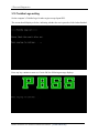
3.19 TOSHIBA Logo Setting…………………..…………………………………………...…..37
3.20 DYNABOOK Logo Setting..............................................................................................39
Chapter 4
4.1
Replacement Procedures
General ........................................................................ Fehler! Textmarke nicht definiert.
Safety Precautions ....................................................... Fehler! Textmarke nicht definiert.
Before You Begin ....................................................... Fehler! Textmarke nicht definiert.
Disassembly Procedures.............................................. Fehler! Textmarke nicht definiert.
viii
[CONFIDENTIAL]
Satellite L670/L675/ Pro L670/L675 Series Maintenance Manual
Assembly Procedures .................................................. Fehler! Textmarke nicht definiert.
Tools and Equipment .................................................. Fehler! Textmarke nicht definiert.
Screw Tightening Torque ............................................ Fehler! Textmarke nicht definiert.
Colors of Screw Shanks .............................................. Fehler! Textmarke nicht definiert.
Symbols of Screws on the Laptop Body ..................... Fehler! Textmarke nicht definiert.
Symbol examples ........................................................ Fehler! Textmarke nicht definiert.
4.2
Battery ......................................................................... Fehler! Textmarke nicht definiert.
Removing the Battery Pack ......................................... Fehler! Textmarke nicht definiert.
Installing the Battery Pack .......................................... Fehler! Textmarke nicht definiert.
4.3
HDD ............................................................................ Fehler! Textmarke nicht definiert.
Removing the HDD ..................................................... Fehler! Textmarke nicht definiert.
Installing the HDD ...................................................... Fehler! Textmarke nicht definiert.
4.4
Memory ....................................................................... Fehler! Textmarke nicht definiert.
Removing the Optional Memory................................. Fehler! Textmarke nicht definiert.
Installing the Optional Memory .................................. Fehler! Textmarke nicht definiert.
4.5
ODD ............................................................................ Fehler! Textmarke nicht definiert.
Removing the ODD ..................................................... Fehler! Textmarke nicht definiert.
Installing the ODD ...................................................... Fehler! Textmarke nicht definiert.
Disassembling the ODD .............................................. Fehler! Textmarke nicht definiert.
Assembling the ODD Drive ........................................ Fehler! Textmarke nicht definiert.
4.6
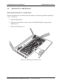
Keyboard Cover and Keyboard .................................. Fehler! Textmarke nicht definiert.
Removing the Keyboard Cover and Keyboard ........... Fehler! Textmarke nicht definiert.
Installing the Keyboard Cover and Keyboard ............. Fehler! Textmarke nicht definiert.
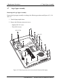
4.7
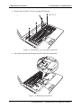
Logic Upper Assembly ............................................... Fehler! Textmarke nicht definiert.
Removing the Logic Upper Assembly ........................ Fehler! Textmarke nicht definiert.
Installing the Logic Upper Assembly ......................... Fehler! Textmarke nicht definiert.
4.8
Touchpad FFC ............................................................ Fehler! Textmarke nicht definiert.
Removing the Touchpad FFC ..................................... Fehler! Textmarke nicht definiert.
Installing the Touchpad FFC ....................................... Fehler! Textmarke nicht definiert.
4.9
WLAN Card ................................................................ Fehler! Textmarke nicht definiert.
Removing the WLAN Card......................................... Fehler! Textmarke nicht definiert.
Satellite L670/L675/ProL670/L675 Series Maintenance Manual
[CONFIDENTIAL]
ix
Installing the WLAN card ........................................... Fehler! Textmarke nicht definiert.
4.10
Modem Card ............................................................... Fehler! Textmarke nicht definiert.
Removing the Modem Card ........................................ Fehler! Textmarke nicht definiert.
Installing the Modem Card.......................................... Fehler! Textmarke nicht definiert.
4.11
USB Board .................................................................. Fehler! Textmarke nicht definiert.
Removing the Right USB Board on the Right Side .... Fehler! Textmarke nicht definiert.
Installing the Right USB Board .................................. Fehler! Textmarke nicht definiert.
4.12
ODD Board ................................................................. Fehler! Textmarke nicht definiert.
Removing the ODD Board .......................................... Fehler! Textmarke nicht definiert.
Installing the ODD switch board ................................ Fehler! Textmarke nicht definiert.
4.13
Touchpad Button Board .............................................. Fehler! Textmarke nicht definiert.
Removing the Touchpad Button Board....................... Fehler! Textmarke nicht definiert.
Installing the touchpad button switch board ............... Fehler! Textmarke nicht definiert.
4.14
Power Board ............................................................... Fehler! Textmarke nicht definiert.
Removing the Power Board ........................................ Fehler! Textmarke nicht definiert.
Installing the Power Board .......................................... Fehler! Textmarke nicht definiert.
4.15
Bluetooth Card ............................................................ Fehler! Textmarke nicht definiert.
Removing the Bluetooth card...................................... Fehler! Textmarke nicht definiert.
Installing the Bluetooth card ....................................... Fehler! Textmarke nicht definiert.
4.16
Display Assembly ....................................................... Fehler! Textmarke nicht definiert.
Removing the Display Assembly ................................ Fehler! Textmarke nicht definiert.
Installing the Display Assembly ................................. Fehler! Textmarke nicht definiert.
4.17
Thermal Fan ................................................................ Fehler! Textmarke nicht definiert.
Removing the Thermal Fan ......................................... Fehler! Textmarke nicht definiert.
Installing the Thermal Fan .......................................... Fehler! Textmarke nicht definiert.
4.18
Motherboard................................................................ Fehler! Textmarke nicht definiert.
Removing the Motherboard ........................................ Fehler! Textmarke nicht definiert.
Installing the Motherboard .......................................... Fehler! Textmarke nicht definiert.
4.19
Speakers ...................................................................... Fehler! Textmarke nicht definiert.
Removing the Speakers ............................................... Fehler! Textmarke nicht definiert.
Installing the Speakers ................................................ Fehler! Textmarke nicht definiert.
x
[CONFIDENTIAL]
Satellite L670/L675/ Pro L670/L675 Series Maintenance Manual
4.20
RJ11 Cable .................................................................. Fehler! Textmarke nicht definiert.
Removing the RJ11 Cable ........................................... Fehler! Textmarke nicht definiert.
Installing the RJ11 Cable ............................................ Fehler! Textmarke nicht definiert.
4.21
CPU and Thermal Module .......................................... Fehler! Textmarke nicht definiert.
Removing the CPU and Thermal Module ................... Fehler! Textmarke nicht definiert.
Installing the CPU and Thermal Module .................... Fehler! Textmarke nicht definiert.
4.22
LCD Bezel .................................................................. Fehler! Textmarke nicht definiert.
Removing the LCD Bezel ........................................... Fehler! Textmarke nicht definiert.
Install the LCD bezel assembly according to the following procedures.Fehler! Textmarke
nicht definiert.
4.23
LCD Module ............................................................... Fehler! Textmarke nicht definiert.
Removing the LCD Module ........................................ Fehler! Textmarke nicht definiert.
Installing the LCD Panel ............................................. Fehler! Textmarke nicht definiert.
4.24
Camera Module ........................................................... Fehler! Textmarke nicht definiert.
Removing the Camera Module ................................... Fehler! Textmarke nicht definiert.
Installing the Camera Module ..................................... Fehler! Textmarke nicht definiert.
4.25
Antennas for WLAN ................................................... Fehler! Textmarke nicht definiert.
Removing the Antennas for WLAN............................ Fehler! Textmarke nicht definiert.
Installing the Antennas for WLAN ............................. Fehler! Textmarke nicht definiert.
Figures
Figure 4.1 Removing the Battery Pack ............................. Fehler! Textmarke nicht definiert.
Figure 4.2 Removing the logic lower door ....................... Fehler! Textmarke nicht definiert.
Figure 4.3 Removing the HDD from the HDD bay .......... Fehler! Textmarke nicht definiert.
Figure 4.4 Removing the HDD aluminum ........................ Fehler! Textmarke nicht definiert.
Figure 4.5 Installing the HDD aluminum ......................... Fehler! Textmarke nicht definiert.
Figure 4.6 Installing the logic lower door......................... Fehler! Textmarke nicht definiert.
Figure 4.7 Removing the RAM from the connectors ....... Fehler! Textmarke nicht definiert.
Satellite L670/L675/ProL670/L675 Series Maintenance Manual
[CONFIDENTIAL]
xi
Figure 4.8 Removing the ODD ......................................... Fehler! Textmarke nicht definiert.
Figure 4.9 Removing the ODD bracket from the ODD .... Fehler! Textmarke nicht definiert.
Figure 4.10 Removing the keyboard cover....................... Fehler! Textmarke nicht definiert.
Figure 4.11 Removing screws securing the keyboard ...... Fehler! Textmarke nicht definiert.
Figure 4.12 Removing the keyboard................................. Fehler! Textmarke nicht definiert.
Figure 4.13 Removing twenty-one screws from the bottom of the laptopFehler! Textmarke nicht
definiert.
Figure 4.14 Removing five screws and disconnecting one FFC from the motherboard Fehler!
Textmarke nicht definiert.
Figure 4.15 Removing the logic upper assembly from the laptop .....Fehler! Textmarke nicht
definiert.
Figure 4.16 Removing the touchpad FFC ......................... Fehler! Textmarke nicht definiert.
Figure 4.17 Removing the WLAN Card ........................... Fehler! Textmarke nicht definiert.
Figure 4.18 Removing two screws securing the modem cardFehler! Textmarke nicht definiert.
Figure 4.19 Disconnecting the cable from the modem cardFehler! Textmarke nicht definiert.
Figure 4.20 Disconnecting the FFC from the motherboardFehler! Textmarke nicht definiert.
Figure 4.21 Disconnecting the ODD board FFC .............. Fehler! Textmarke nicht definiert.
Figure 4.22 Removing the touchpad button board ........... Fehler! Textmarke nicht definiert.
Figure 4.23 Disconnecting the FFC from the motherboardFehler! Textmarke nicht definiert.
Figure 4.24 Removing the power board ........................... Fehler! Textmarke nicht definiert.
Figure 4.25 Removing the Bluetooth card ........................ Fehler! Textmarke nicht definiert.
Figure 4.26 Disconnecting the Bluetooth cable ................ Fehler! Textmarke nicht definiert.
Figure 4.27 Removing the display assembly .................... Fehler! Textmarke nicht definiert.
Figure 4.28 Removing the thermal fan from the logic lower assemblyFehler! Textmarke nicht
definiert.
Figure 4.29 Removing the motherboard from the logic lower assemblyFehler! Textmarke nicht
definiert.
Figure 4.30 Removing the speakers.................................. Fehler! Textmarke nicht definiert.
Figure 4.31 Pulling out the cable from the routing channelFehler! Textmarke nicht definiert.
Figure 4.32 Removing the RJ11 connector ...................... Fehler! Textmarke nicht definiert.
Figure 4.33 Removing the Thermal Module spring screwsFehler! Textmarke nicht definiert.
Figure 4.34 Removing the Thermal Module spring screwsFehler! Textmarke nicht definiert.
Figure 4.35 Removing the CPU ........................................ Fehler! Textmarke nicht definiert.
xii
[CONFIDENTIAL]
Satellite L670/L675/ Pro L670/L675 Series Maintenance Manual
Figure 4.36 Reapply the Shinetsu 7726 grease on the thermal module and remove any release
papers ........................................................ Fehler! Textmarke nicht definiert.
Figure 4.37 Removing the LCD Bezel ............................. Fehler! Textmarke nicht definiert.
Figure 4.38 Prying up the LCD Bezel .............................. Fehler! Textmarke nicht definiert.
Figure 4.39 Removing the LCD Bezel ............................. Fehler! Textmarke nicht definiert.
Figure 4.40 Removing the LCD Module from the LCD cover assemblyFehler! Textmarke nicht
definiert.
Figure 4.41 Disconnect the camera module cable ............ Fehler! Textmarke nicht definiert.
Figure 4.42 Removing the LCD hinges ............................ Fehler! Textmarke nicht definiert.
Figure 4.43 Removing the LVDS cable from the LCD panelFehler! Textmarke nicht definiert.
Figure 4.44 Installing the LCD hinges.............................. Fehler! Textmarke nicht definiert.
Figure 4.45 Removing the Camera Module...................... Fehler! Textmarke nicht definiert.
Figure 4.46 Removing the antennas from the LCD cover assembly Fehler! Textmarke nicht
definiert.
Appendices
Appendix A
Handling the LCD Module ....................................................................................A-1
Appendix B
Board Layout ......................................................................................................... B-1
Appendix C
Pin Assignments..................................................................................................... C-1
Appendix D
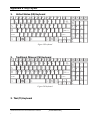
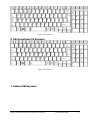
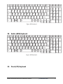
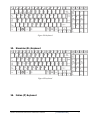
Keyboard Scan/Character Codes ...........................................................................D-1
Appendix E
Key Layout............................................................................................................. E-1
Appendix F
Series Screw Torque List ....................................................................................... F-1
Appendix G
Reliability...............................................................................................................G-1
Satellite L670/L675/ProL670/L675 Series Maintenance Manual
[CONFIDENTIAL]
xiii
1 Hardware Overview
Chapter 1
Hardware Overview
Satellite L670/Pro L670 Maintenance Manual[CONFIDENTIAL]
1 Hardware Overview
Chapter 1
Contents
1.1
Features .................................................................................................................. 1-1
1.2
2.5-inch HDD ....................................................................................................... 1-10
1.3
DVD Super Multi (+-R Double Layer) ................................................................ 1-11
1.4
BD-Writer and BD-Combo drives ....................................................................... 1-12
1.5
Power Supply ....................................................................................................... 1-13
1.6
Batteries ................................................................................................................ 1-15
1.6.1
Main Battery ......................................................................................... 1-15
1.6.2
Battery Charging Control ..................................................................... 1-15
1.6.3
RTC Battery .......................................................................................... 1-16
[CONFIDENTIAL] Satellite L670/Pro L670 Maintenance Manual
1 Hardware Overview
Figures
Figure 1-1A
ID Parts Description Placement Part A.......................................................... 1-5
Figure 1-2
SATA HDD ................................................................................................. 1-10
Figure 1-3
DVD Super Multi Drive .............................................................................. 1-11
Figure 1-4
BD-Writer or BD-Combo drive (depending on the model) ......................... 1-12
Tables
Table 1-1
HDD Specifications ..................................................................................... 1-10
Table 1-2
DVD Super Multi Drive Specifications ....................................................... 1-11
Table 1-3
Blu-ray Disc Drive specifications ................................................................ 1-12
Table 1-4
Quick/Normal Charging Time ..................................................................... 1-15
Satellite L670/Pro L670 Maintenance Manual[CONFIDENTIAL]
1.1 Features
1.1
1 Hardware Overview
Features
The Toshiba Satellite L670/Pro L670 is a full-size PC notebook equipped with a Dual Core
Processor, providing high-speed processing capabilities and advanced features. The computer
employs a lithium ion battery that allows it to be battery-operated for long periods of time. The
display uses 17.3-inch WXGA LCD panel. Many features can be Built To Order (BTO) to
customize the system for each user.
The computer has the following features:
Processor (BTO)
The computer is equipped with one of the following Intel® processors:
Intel® Arrandale Processor
Memory (BTO)
The computer has two SODIMM slots which come standard with 1GB/2GB/4GB, accepting
BTO for your memory requirements. It can incorporate up to 8 GB of main memory and
supports DDR3 at 1333MHz (Works as 1066MHz)/1066MHz/800MHz.
Battery Pack
The computer is powered by one rechargeable and removable lithium ion battery pack. The
capacity can be either 3-cell, 6-cell or 12-cell, depending on the model of the computer.
RTC Battery
The internal RTC battery backs up the Real Time Clock and calendar.
Hard Disk Drive (HDD) (BTO)
The computer accommodates a 9.5 mm HDD with the following storage capacities:
y 250/320/400/500/640 GB, S-ATA (5,400rpm)
y 500 GB, S-ATA (7,200rpm)
[CONFIDENTIAL]Satellite L670/Pro L670 Maintenance Manual
1 Hardware Overview
1.1 Features
ODD (BTO)
y 12.7mm height DVD Super Multi drive supporting ±R Double Layer
y 12.7mm height DVD Super Multi drive supporting ±R Double Layer w/ Labelflash
y 12.7mm height BD-Combo drive
y 12.7mm height BD Writer drive
Display
The LCD display comes with the following:
y 17.3" W (16:9) HD+ (1600x900) LED CSV and Non-CSV Type.
Graphics (BTO)
Mobile Intel® HM55/HM57 Chipset for integrated graphics display
ATI Mobility RadeonTM HD 5145/HD5470/HD5650 (DDR3, 1024MB)for external
graphics support
(depending on model)
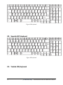
Keyboard
The computer is equipped with a Toshiba standard 360mm keyboard, which has A4 +
10key Genchaku Keyboard without stick-point. It is a Win7-compliant keyboard with
optional Windows keys and application keys.
Pointing Device
The integrated Wide Touch Pad and two control buttons in the palm rest allow control of
the on-screen pointer and support functions such as the scrolling of windows.
External Monitor Port
The analog VGA port provides support for VESA DDC2B compatible functions. A WDDM
driver is ready for Win7.
Universal Serial Bus (USB) Ports
The computer has two USB 2.0 ports along with one USB/eSATA combo port (see below).
It is supported to daisy-chain a maximum of 127 USB devices. The serial data transfer rate
is 480 Mbps or 12 Mbps and 1.5 Mbps. These ports support PnP installation and hot
plugging.
Satellite L670/Pro L670 Maintenance Manual[CONFIDENTIAL]
1.1 Features
1 Hardware Overview
eSATA
The external SATA or eSATA port executes high-speed data transfer to external devices
and supports shielded cable lengths of up to 2 meters outside the PC. The port also provides
dual USB compatibility.
Bridge Media Slot
This slot allows you to insert SD/SDHC/SDXC memory card, miniSD/microSD Card,
Memory Stick (PRO), and MultiMediaCard. It supports high-speed SD, SDHC and SDXC.
This model does not support CF, SmartMedia cards, xD or Memory Stick Duo cards.
Sound system
The integrated sound system is composed of two Realtek Azalia internal speakers, an
internal microphone (BTO with internal camera), and standard Microphone-IN and
Headphone-OUT ports. Dolby® Advanced Audio function is also integrated in the system.
Internal Camera (BTO)
It supports 0.3M and 1.3M pixels with Auto Macro and comes with a blue LED indicator.
An internal microphone is BTO with the internal camera and includes echo cancellation.
The camera is not a rotation type.
Headphones/Line-out Jack
This jack connects digital speakers or stereo headphones (16 ohm minimum). When
connected to digital speakers or headphones, the internal speaker is automatically disabled.
Microphone/ Line-in Jack
A 3.5mm mini microphone jack enables connection of a three-conductor microphone for
monaural input and also enables the connection of a stereo device for audio input.
HDMI Out Port (BTO)
The HDMI out port can connect with a Type A connector HDMI cable. The HDMI out port
can send SD and HD video/audio signals.
[CONFIDENTIAL]Satellite L670/Pro L670 Maintenance Manual
1 Hardware Overview
1.1 Features
LAN (BTO)
The computer has built-in support for 10M/100M Ethernet LAN (10/100 megabits per
second, 10/100BASE-T). It employs a Realtek RTL8105E for 10M/100Mbit LAN (for
discrete platform, Realtek RTL8111E for 10M/100M/1000M is employed). It is preinstalled as a standard device in some markets.
Wireless LAN (BTO)
Some computers in this series are equipped with a Wireless LAN (WLAN) card. This
WLAN module may come with the following types (depending on the model):
Atheros 802.11 b/g (HB95 1x1n)
Realtek 802.11 b/g/n (8191SE)
Internal Modem (BTO)
Some models are equipped with an integrated modem. The integrated modem provides
capability for data and fax communications that support the V.90 (V.92) standards and
includes a modem jack for connection to the telephone line. Please note that both the V.90
and V.92 standards are only supported in the USA, Canada, United Kingdom, France,
Germany and Australia - only the V.90 standard is supported in other regions. You should
also be aware that the speed of data and fax transfer will depend on the analog telephone
line conditions. The integrated model is only installed as a standard device in some markets.
This internal modem comes with MDC 1.5 solution (Azalia interface).
Bluetooth (BTO)
Some computers in this series offer Bluetooth wireless communication functionality which
eliminates the need for cables between electronic devices such as computers and printers.
When implemented, Bluetooth provides wireless communication in a small space. This
module is Version 2.1 + EDR (BCM2070 Flash SLIM with Antenna), ie – Toshiba stack
support.
Satellite L670/Pro L670 Maintenance Manual[CONFIDENTIAL]
1.1 Features
1 Hardware Overview
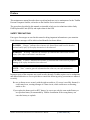
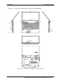
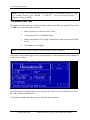
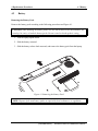
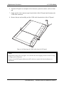
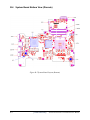
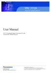
Figure 1-1A shows the computer and its system unit configuration.
CAMERA
Printing sub-brand
SPEAKER
SPEAKER
KENSINGTON LOCK
THERMAL VAN HOLES
VGA
RJ45
ODD
eSATA/USB
TOUCH PAD ON/OFF BTN
HDMI
TOUCH PAD
TP BTN
USB
USB
MICROPHONE
HEADPHONE
Bridge Media Slot
MAIN BATTERY
POWER
HDD/ODD/ESATA ACCESS
BRIDGE MEDIA ACCESS
DC IN
WIRELESS ACCESS
LED Lens
& RAM DOOR
Figure 1-1A
ID Parts Description Placement Part A
[CONFIDENTIAL]Satellite L670/Pro L670 Maintenance Manual
1 Hardware Overview
1.1 Features
A
B
C
Compal Confidential
D
E
Fan Control
Intel Arrandale
Model Name : NALAA
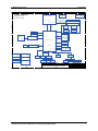
File Name : LA-6041P
Clock Generator
APL5607KI-TRG
RTM890N-631-GRT
page 6
page 13
1
1
Memory BUS(DDRIII) 200pin DDRIII-SO-DIMM X2
rPGA-989
Dual Channel
BANK 0, 1, 2, 3
1.5V DDRIII 800/1066 MT/s
page 5,6,7,8,9,10
USB/B
FDI X8
DMI X4
2.7GHz
2.5GHz
page 11,12
BT conn
USB port 0,1
USB port 5
page 26
page 30
3IN1 RTS5138-GR
USB port 10
USB port 11
page 31
USB
LCD Conn.
Int. Camera
page 13
5V 480MHz
page 13
2
2
CRT
PCIeMini Card
WiMax
page 14
USB
USB port 13
page 27
5V 480MHz
HDMI Conn.
PCIe 1x
HDMI Level Shifter
PCIeMini Card
WLAN
1.5V 2.5GHz(250MB/s)
page 15
PCIe port 2
page 27
Intel Ibex Peak
page 15
SATA port 1
5V 3GHz(300MB/s)
RJ45
PCIe 1x
RTL8105E-GR 10/100M
page 28
PCIe port 1
page 28
SATA port 4
BGA-951
1.5V 2.5GHz(250MB/s)
5V 3GHz(300MB/s)
3
SATA HDD
page 25
SATA ODD
page 25
3
SATA port 5
5V 3GHz(300MB/s)
USB port 3
Power/B
5V 480MHz
HD Audio
RTC CKT.
page 34
page 25
USB
USB port 3
page 25
3.3V/1.5V 24MHz
HDA Codec
MDC 1.5 Conn
page 16
SPI ROM
page 16
USB/B
3.3V 33 MHz
LPC BUS
page 16~24
eSATA
page 30
DC/DC Interface CKT.
page 25
Power Circuit DC/DC
Debug Port
ENE KB926 E0
page 33
ALC259-GR
page 26
page 29
page 32
page 35
Touch Pad
4
ODD/B
page 26
Int.KBD
page 33
2009/01/23
Issued Date
Deciphered Date
B
C
Satellite L670/Pro L670 Maintenance Manual[CONFIDENTIAL]
HP CONN
page 30
SPK CONN
page 30
4
Compal Electronics, Inc.
2010/01/23
THIS SHEET OF ENGINEERING DRAWING IS THE PROPRIETARY PROPERTY OF COMPAL ELECTRONICS, INC. AND CONTAINS CONFIDENTIAL
AND TRADE SECRET INFORMATION. THIS SHEET MAY NOT BE TRANSFERED FROM THE CUSTODY OF THE COMPETENT DIVISION OF R&D
DEPARTMENT EXCEPT AS AUTHORIZED BY COMPAL ELECTRONICS, INC. NEITHER THIS SHEET NOR THE INFORMATION IT CONTAINS
MAY BE USED BY OR DISCLOSED TO ANY THIRD PARTY WITHOUT PRIOR WRITTEN CONSENT OF COMPAL ELECTRONICS, INC.
A
MIC CONN
page 30
Compal Secret Data
Security Classification
page 36~44
Int.
MIC CONN
(LVDS CONN)
page 13
EC ROM
page 26
D
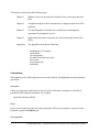
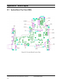
Title
Block Diagrams
Size
Document Number
Rev
1.0
NALAA LA-6041P M/B
Date:
Thursday, February 25, 2010
Sheet
E
2
of
48
1.1 Features
1 Hardware Overview
A
B
C
D
Compal Confidential
E
Fan Control
PCIE-Express 16X 2.5GHz
1
VGA Thermal Sensor
APL5607KI-TRG
Intel Arrandale
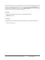
Model Name : NALAA
File Name : LA-6042P
Clock Generator
ADM1032ARMZ-2R
page 6
RTM890N-631-GRT
page 21
page 22
1
rPGA-988
Memory BUS(DDRIII) 204pin DDRIII-SO-DIMM X2
Dual Channel
page 5,6,7,8,9,10
VGA (DDR3)
ATI M92 XTX,64bit with 512MB
ATI Park XT,64bit with 512MB
ATI Madison LP,128bit with 1GB
page 11,12
BANK 0, 1, 2, 3
1.5V DDRIII 800/1066 MT/s
DMI X4
AUDIO & USB/B
BT conn
USB port 0,1
USB port 5
page 35
page 39
2.5GHz
3IN1 RTS5138-GR
USB port 10
page 13,14,15,16,17,18,19,20,21
Int. Camera
USB port 11
page 40
USB
page 22
5V 480MHz
2
LCD Conn.
page 22
CRT
2
HDMI Conn.
page 23
page 24
PCIeMini Card
WLAN
USB
5V 480MHz
USB port 13
page 36
PCIe 1x
1.5V 2.5GHz(250MB/s)
PCIe port 2
page 36
Intel Ibex Peak
SATA port 1
BGA-951
5V 3GHz(300MB/s)
SATA port 4
5V 3GHz(300MB/s)
3
RJ45
page 37
RTL8105E-VB-GR 10/100M
RTL8111E-VB-GR Giga
PCIe port 1
PCIe 1x
page 34
SATA ODD
page 34
3
SATA port 5
1.5V 2.5GHz(250MB/s)
page 37
SATA HDD0
5V 3GHz(300MB/s)
page 25,26,27,28,29,30,31,32,33
USB port 3
eSATA
page 34
Power/B
3.3V 33 MHz
LPC BUS
5V 480MHz
HD Audio
DC/DC Interface CKT.
page 43
SPI ROM
page 25
Debug Port
ENE KB926 E0
page 42
HDA Codec
ALC259-GR
page 35
page 38
page 41
Digital MIC
Power Circuit DC/DC
page 39
USB port 3
page 34
3.3V/1.5V 24MHz
MDC 1.5 Conn
page 44
AUDIO & USB/B
USB
page 45~54
4
ODD/B
Touch Pad
page 34
page 35
RTC Circuit
Int.KB
LCD Conn.
EC ROM
page 35
page 22
page 42
AUDIO & USB/B
USB port 0,1
SPK CONN
4
page 39
page 39
page 25
LED/B
Compal Electronics, Inc.
Compal Secret Data
Security Classification
page 43
2009/10/01
Issued Date
Deciphered Date
2010/10/01
THIS SHEET OF ENGINEERING DRAWING IS THE PROPRIETARY PROPERTY OF COMPAL ELECTRONICS, INC. AND CONTAINS CONFIDENTIAL
AND TRADE SECRET INFORMATION. THIS SHEET MAY NOT BE TRANSFERED FROM THE CUSTODY OF THE COMPETENT DIVISION OF R&D
DEPARTMENT EXCEPT AS AUTHORIZED BY COMPAL ELECTRONICS, INC. NEITHER THIS SHEET NOR THE INFORMATION IT CONTAINS
MAY BE USED BY OR DISCLOSED TO ANY THIRD PARTY WITHOUT PRIOR WRITTEN CONSENT OF COMPAL ELECTRONICS, INC.
A
B
C
D
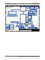
Title
Block Diagrams
Size
Document Number
Rev
1.0
NALAA LA6042P M/B
Date:
Thursday, February 04, 2010
Sheet
2
of
57
E
[CONFIDENTIAL]Satellite L670/Pro L670 Maintenance Manual
1 Hardware Overview
1.1 Features
The system unit of the computer consists of the following components:
Processor (BTO)
The computer is equipped with one of the following Intel® processors:
Intel® Arrandale Processor
Memory (BTO)
The computer has two SODIMM slots which come standard with 1GB/2GB/4GB, accepting
BTO for your memory requirements. It can incorporate up to 8 GB of main memory. It
supports DDR3 at 1333MHz (Works as 1066MHz)/1066MHz/800MHz.
BIOS ROM (EEPROM)
The system BIOS uses one 4096KB flash ROM and the keyboard BIOS uses another
256KB flash ROM. The flash utility can be used to program both system and keyboard
BIOS at the same time.
System Controllers
Advanced Power Management 1.2 support
ACPI 4.0b and Windows Logo Program 3.0 compliant
Support SMBIOS specification V2.4
Hot keys for system control
Audio volume output control
External LED control
Battery scope report and control
Sticky key support
Power switch control
Two host interface channels support
Supports three independent devices
Internal Keyboard country selection
Computrace
Satellite L670/Pro L670 Maintenance Manual[CONFIDENTIAL]
1.1 Features
1 Hardware Overview
Graphics Controller
Intel® HM55/HM57 Chipset for integrated graphics display
ATI Mobility RadeonTM HD5145/HD5470/HD5650 (DDR3, 1024MB)for external
graphics support
Audio Controller
Realtek Azalia ALC259
One Audio-in port: Mic-in/Line-in
One Audio-out port: Headphone-out/Line-out
Internal Microphone (with Internal Camera, MIC with echo cancellation)
Volume control: Digital control
Microsoft inbox audio driver support
Software EQ support
Wireless LAN Controller
Atheros 802.11 b/g (HB95 1x1n)
Realtek 802.11 b/g/n (8191SE)
WPS supported
[CONFIDENTIAL]Satellite L670/Pro L670 Maintenance Manual
1 Hardware Overview
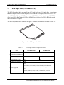
1.2
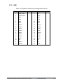
1.2 2.5-inch HDD
2.5-inch HDD
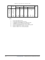
The computer contains an extremely low-profile and lightweight, high-performance HDD. The
HDD incorporates a 9.5 mm magnetic disk and mini-Winchester type magnetic heads. The HDD
interface conforms to Serial ATA. Storage capacities supported are 250, 320, 400, 500 and 640
GB.
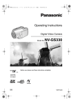
The HDD is shown in Figure 1-2 and some of its specifications are listed in Table 1-1.
Figure 1-2
Table 1-1
SATA HDD
HDD Specifications
Specifications
Item
Capacity (GB)
Rotational Speed (RPM)
Height
User Data Sectors
Bytes / Sector
250G
320 GB
400G
5400 RPM
5400 RPM
5400 RPM
9.5 mm
9.5 mm
9.5 mm
488,397,168
625,142,448
781,422,768
512
512
512
Specifications
Item
Capacity (GB)
Rotational Speed (RPM)
Height
User Data Sectors
Bytes / Sector
500G
640 GB
5400 RPM
5400 or 7200 RPM
9.5 mm
9.5 mm
976,773,168
1,250,263,728
512
512
Satellite L670/Pro L670 Maintenance Manual[CONFIDENTIAL]
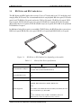
1.3 DVD Super Multi (+-R Double Layer)
1.3
1 Hardware Overview
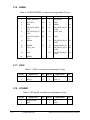
DVD Super Multi (+-R Double Layer)
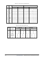
The DVD Super Multi drive accepts 12-cm (4.72-inch) and 8-cm (3.15-inch) discs. At maximum,
the drive can play back a DVD at 8x speed, read CD-ROM at 24x speed, and write CD-R at 24x
speed, CD-RW at 24x speed, DVD-R at 8x speed, DVD-R (Dual Layer) at 6x speed, DVD-RW
at 6x speed, DVD+R at 8x speed, DVD+R (Double Layer) at 6x speed, DVD+RW at 8x speed
and DVD-RAM at 5x speed.
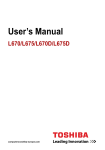
The DVD Super Multi drive is shown in Figure 1-3 and its specifications are listed in Table 1-2.
Figure 1-3
Table 1-2
DVD Super Multi Drive
DVD Super Multi Drive Specifications
Item
DVD-ROM Mode
CD-ROM Mode
33.3 (U-DMA transfer mode 2)
Data Transfer Rate (Mbytes/s)
16.6 (PIO mode 4, Multiword DMA mode 2)
Access Time (ms)
Average Random Access
130
130
Data Buffer Size (Mbytes)
2MB
DVD:
Formats Supported
DVD-VIDEO, DVD-ROM, DVD-R, DVD-RW, DVD-R (Double
Layer), DVD+R, DVD+RW, DVD+R (Double Layer), DVD-RAM.
CD:
CD-DA, CD-ROM, CD-R, CD-RW, CD-ROMXA, Photo CD
(Multi-Session), Video CD, CD-Extra (CD+), CD-Text.
[CONFIDENTIAL]Satellite L670/Pro L670 Maintenance Manual
1 Hardware Overview
1.4
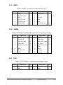
1.4 BD-Writer and BD-Combo drives
BD-Writer and BD-Combo drives
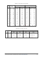
The BD-Writer and BD-Combo drives accept 12-cm (4.72-inch) and 8-cm (3.15-inch) discs and
can play BDs, DVDs and CDs. At maximum the drives can playback BD at 6x speed, DVD at 8x
speed, read CD-ROM at 24x speed, and write, CD-R at 24x speed, CD-RW at 16x speed, DVDR at 8x speed, DVD-R (Dual Layer) at 4x speed, DVD-RW at 6x speed, DVD+R at 8x speed
(BD-Combo drive at 4x speed), DVD+R (Double Layer) at 4x speed, DVD+RW at 8x speed and
DVD-RAM at 5x speed.
In addition to being able to write to recordable CD/DVD discs, the BD-Writer drive can write to
BD-R at 6x speed, BD-R (DL) at 4x speed, BD-RE at 2x speed and BD-RE (DL) at 2x speed.
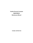
Figure 1-4
BD-Writer or BD-Combo drive (depending on the model)
Table 1-3
Item
Blu-ray Disc Drive specifications
BD-ROM Mode
DVD-ROM Mode
CD-ROM Mode
33.3 (U-DMA transfer mode 2)
Data Transfer Rate (Mbytes/s)
16.6 (PIO mode 4, Multiword DMA mode 2)
Access Time (ms)
Average Random Access
130
Data Buffer Size (Mbytes)
2MB
BD:
BD-ROM, BD-R, BD-R (DL), BD-RE, BD-RE (DL)
DVD:
Formats Supported
DVD-VIDEO, DVD-ROM, DVD-R, DVD-RW, DVD-RAM, DVD+R,
DVD+-R (Double Layer), DVD+RW.
CD:
CD-DA, CD-ROM, CD-R, CD-RW, CD-ROMXA, Photo CD
(Multi-Session), Video CD, CD-Extra (CD+), CD-Text.
Satellite L670/Pro L670 Maintenance Manual[CONFIDENTIAL]
1.5 Power Supply
1.5
1 Hardware Overview
Power Supply
The power supply unit provides constant voltage (19V) for the system board and performs the
following functions:
1. Power input monitor
y Checks whether the AC adapter (DC power supply) is connected to the computer.
y Checks whether the battery pack is connected to the computer.
y Monitors the DC power supply input voltage (AC Adapter output voltage).
2. Power supply's internal control
y Turns on and off the battery pack charging power supply.
y Issues a charging current instruction to the PWM control IC of the battery pack charging
power supply.
y Controls the supply of DC power supply input (AC Adapter output) to the power supply
unit.
y Controls the supply of power to the system block (load/logic circuit side).
y Controls forced shutdown if the power supply malfunctions.
3. Logic circuit control
y Instructs the gate array to enable/disable tuning the power on.
y Controls power-on/off operation.
4. Status display
y Turns on the Power LED (in White).
y Battery indicator (in White or Amber).
y DC-IN indicator (in White)
5. External interface
y Performs communication through the I2C bus (via the internal EC/KBC).
y Transfers the power supply operation mode.
[CONFIDENTIAL]Satellite L670/Pro L670 Maintenance Manual
1 Hardware Overview
1.5 Power Supply
6. Output monitor
y Monitors the voltage output to the system block (load/logic circuit side).
y Monitors the voltage, over-voltage, input/output current of the battery pack.
y Monitors the internal temperature of the battery pack.
y Monitors the supply voltage from the AC adapter.
Satellite L670/Pro L670 Maintenance Manual[CONFIDENTIAL]
1.6 Batteries
1.6
1 Hardware Overview
Batteries
The computer has the following two types of batteries:
Main Battery Pack
Real Time Clock (RTC) Battery
1.6.1
Main Battery
The main battery pack serves as the computer's main power source when the AC adapter is not
attached. The main battery maintains the state of the computer when the AC adapter is detached.
1.6.2
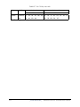
Battery Charging Control
Battery charging is controlled by EC KB926. When the AC adapter and battery pack are attached
to the computer, the EC KB926 controls the charge on/off state and detects a full charge.
Battery Charge
When the AC adapter is attached, the battery is charged by off-state charge when the system
is powered off or by on-state charge when it is powered on.
Table 1-4
Quick/Normal Charging Time
State
Charge Time
Off-State Charge
3/6/12 Cell
About 4 hours max
On-State Charge
3/6/12 Cell
About 12 hours max
[CONFIDENTIAL]Satellite L670/Pro L670 Maintenance Manual
1 Hardware Overview
1.6 Batteries
NOTE: The time required for normal charge depends on the power consumption by the
system. Using a fluorescent lamp and frequently accessing the disk consumes more power and
lengthens the charge time.
Any of the following can stops battery charge:
1. The battery becomes fully charged.
2. The AC adapter or battery pack is removed.
3. The battery or AC adapter voltage is abnormal.
Detection of full charge
A full charge is detected only when the battery is being charged by quick or normal charge.
A full charge is detected when either of the following conditions is met:
1. The current in the battery charging circuit drops below the predetermined value.
2. The charging time exceeds the fixed limit.
1.6.3
RTC Battery
The RTC battery provides power to keep the current date, time and other system information in
memory while the computer is turned off.
Satellite L670/Pro L670 Maintenance Manual[CONFIDENTIAL]
2 Troubleshooting Procedures
Chapter 2
Troubleshooting Procedures
Satellite L670/L675/ProL675 Series Maintenance Manual [CONFIDENTIAL]
2 Troubleshooting Procedures
Chapter 2
Contents
2.1
Troubleshooting Introduction…………………………………………………….…... 3
2.2
Troubleshooting Flowchart ……………………………………………………………4
2.3
Power Supply Troubleshooting………………………………………………………. 9
2.4
Display Troubleshooting ..............................................................................................14
2.5
Keyboard Troubleshooting ..........................................................................................17
2.6
External USB Devices Troubleshooting ......................................................................19
2.7
TouchPad Troubleshooting ..........................................................................................21
2.8
Speaker Troubleshooting .............................................................................................23
2.9
Optical Drive Troubleshooting ....................................................................................25
2.10
Modem Troubleshooting …………………………………………………………… 28
2.11
Wireless LAN Troubleshooting ...................................................................................30
2.12
Camera Troubleshooting……………………………………………………………. 32
2.13
Bluetooth Troubleshooting…………………...…………………………….……….. 34
2.14
Bridge Media slot Troubleshooting……………………………………………..…... 36
2.15
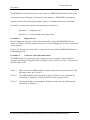
HDD Troubleshooting………………………………………………………………..38
2.16
CRT failure Troubleshooting ……………………………………………………….. 40
2.17
HDMI Troubleshooting …………………………………………………………….. 42
2.18
MIC Troubleshooting ………………………………………………………………. 44
2.19
E-SATA Troubleshooting ………………………………………….……………….. 46
2.20
LAN Troubleshooting………………………………………………………………...48
[CONFIDENTIAL]
ual
Satellite L670/L675/ProL670 Series Maintenance Man
2 Troubleshooting Procedures
Figures
Figure 2-1
Troubleshooting Flowchar(1/2) ………………………………………………6
Figure 2-1
Troubleshooting Flowchart (2/2) ……………………………………………...8
Figure 2-2
Power Supply Troubleshooting Process……………………………………….9
Figure 2-3
Display Troubleshooting Process .................................................................... 16
Figure 2-4
Keyboard Troubleshooting Process................................................................. 17
Figure 2-5
External USB Device Troubleshooting Process .............................................. 19
Figure 2-6
TouchPad Troubleshooting Process ................................................................ 21
Figure 2-7
Speaker Troubleshooting Process ................................................................... 23
Figure 2-8
Optical Drive Troubleshooting Process .......................................................... 25
Figure 2-9
Modem Troubleshooting Process………………………...…………………..28
Figure 2-10
Wireless LAN Troubleshooting Process………………………………...…...30
Figure 2-11
Camera Troubleshooting Process…………………………………………….32
Figure 2-12
Bluetooth Troubleshooting Process…..…………..………………….……….34
Figure 2-13
3 in 1 Card TroubleshootingProcess…………………………..…….………..36
Figure 2-14
HDD Troubleshooting Process…………………………….………………....38
Figure 2-15
CRT Failure Troubleshooting Process ………………………..……………...40
Figure 2-16
HDMI Troubleshooting Process …………………………………………......42
Figure 2-17
MIC Troubleshooting Process ………………………….……………….…...44
Figure 2-18
E-SATA Troubleshooting Process ……………………...….………………...46
Figure 2-19
LAN Troubleshooting Process …………………...…….………………….....48
Tables
Table 2-1
Battery LED ....................................................................................................... 12
Table 2-2
DC-IN LED ........................................................................................................ 13
2.1
Troubleshooting Introduction
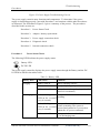
Chapter 2 describes how to determine if a Field Replaceable Unit (FRU) in the computer is
causing the computer to malfunction. The FRUs covered are:
Satellite L670/L675/ProL670 Series Maintenance Manual
[CONFIDENTIAL]
2-iii
2 Troubleshooting Procedures
1. Display
5. Touch Pad
9. Wireless LAN
13. MIC
2. USB Floppy Drive 6. Speaker/Head
10. Camera
14. E-SATA
3. Keyboard
7. Optical Drive
11. Bluetooth
15. LAN
4. USB ports
8. Modem
12. HDMI
The Diagnostics Disk operations are described in Chapter 3. Detailed replacement
procedures are given in Chapter 4.
The following tools are necessary for implementing the troubleshooting procedures:
1. Phillips screwdriver (3.5 mm)
2. 2DD or 2HD formatted work disk for floppy disk drive testing
3. Multimeter
4. External monitor
5. USB compatible keyboard
6. Multimedia sound system with line-in and line-out ports
7. Headphones
8. USB test module and USB cable
9. Music CD
10. MIC module and MIC line
11. E-SATA HDD
12. HDMI
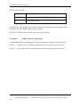
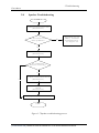
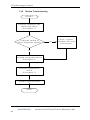
2.2
Troubleshooting Flowchart
If you know the location of the malfunction, turn directly to the appropriate section of this
chapter. If the problem is unspecified, use the flowchart in Figure 2-1 as a guide for
[CONFIDENTIAL]
ual
Satellite L670/L675/ProL670 Series Maintenance Man
2 Troubleshooting
Procedures
determining which troubleshooting procedures to execute. Before performing any
troubleshooting procedures, verify the following:
z
Ask the user if a password is registered, if it is, ask him or her to enter the password.
z
Verify with the customer that Toshiba Windows7 is installed on the hard disk. Operating
systems that were not preinstalled by Toshiba can cause the computer to malfunction.
z
Make sure all optional equipment is removed from the computer.
z
Make sure the optical disk drive, if installed, is empty. If no ODD module is installed,
you should use an external ODD to run the diagnostics tests
Satellite L670/L675/ProL670 Series Maintenance Manual
[CONFIDENTIAL]
2-iii
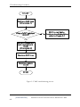
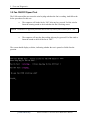
2 Troubleshooting Procedures
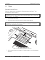
START
C onnect the A C adapter to the D C -IN
socket
Is the D C -IN L E D on?
No
P erform the P ow er S upply
T roubleshooting procedures in
section 2.3
Y es
Is the B attery L E D on?
No
P erform the P ow er S upply
T roubleshooting procedures in
section 2.3
No
P erform the P ow er S upply
T roubleshooting procedures in
section 2.3
Y es
T urn the P ow er sw itch on
Y es
Is the P ow er O n L E D on?
Y es
Is the B IO S logo m essage display?
No
P erform the P ow er S upply
T roubleshooting procedures in
section 2.3
Y es
If the "passw ord" m essage displays,
type the passw ord, then press E nter.
Is T oshiba W indow s7 being loaded?
No
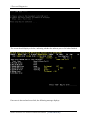
P erform diagnostics program .
R un C M 165.E X E and select the
H A R D D IS K item .
Y es
A
[CONFIDENTIAL]
ual
Satellite L670/L675/ProL670 Series Maintenance Man
2 Troubleshooting
Procedures
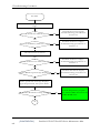
Figure 2-1 Troubleshooting flowchart (1/2)
Satellite L670/L675/ProL670 Series Maintenance Manual
[CONFIDENTIAL]
2-iii
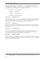
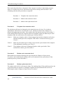
2 Troubleshooting Procedures
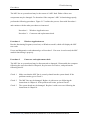
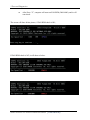
A
Does typed characters appear correctly?
No
Perform the Keyboard
Troubleshooting
procedures in section 2.4
No
Perform the USB memory/
CD disk
Troubleshooting
procedures in section 2.5
Yes
After confirming which
diagnostics test has
detected an error, perform
the appropriate procedure
as outlined below.
Yes
Insert USB memory/CD disk,
Then run the diagnostics test program.
Yes
Is the diagnostics test loaded?
Yes
Allow each test to perform
automatically
Is an error detected by any of the
diagnostics tests?
No
System is normal
End
[CONFIDENTIAL]
ual
Satellite L670/L675/ProL670 Series Maintenance Man
2 Troubleshooting
Procedures
Figure 2-1 Troubleshooting flowchart (2/2)
Satellite L670/L675/ProL670 Series Maintenance Manual
[CONFIDENTIAL]
2-iii
2 Troubleshooting Procedures
If the diagnostics program cannot detect an error, the problem may be intermittent. The test
program should be executed several times to isolate the problem. When a problem has been
located, perform the appropriate troubleshooting procedures as follows:
1. If an error is detected by the battery test, perform the Power Supply Troubleshooting
Procedures in Section 2.3
2. If an error is detected by the display test, perform the Display Troubleshooting
Procedures in Section 2.4
3. If an error is detected by the keyboard test, perform the Keyboard Troubleshooting
Procedures in Section 2.5
4. If an error is detected by the Touchpad test, perform the Touchpad Troubleshooting
Procedures in Section 2.7
5. If an error is detected by the audio test, perform the Speaker Troubleshooting
procedures in Section 2.8 and the Optical Drive Troubleshooting Procedures in
Section 2.9
6. If an error is detected by the HDD test, perform the HDD Troubleshooting Procedures
in Section 2.15
[CONFIDENTIAL]
ual
Satellite L670/L675/ProL670 Series Maintenance Man
2 Troubleshooting
Procedures
Other problems that are not covered by the diagnostics program may be discovered by a
user.
1. If an error is detected when using an external USB device, perform the External USB
Devices Troubleshooting Procedures in Section 2.6
2. If an error is detected when using the modem, perform the Modem Troubleshooting
Procedures in Section 2.10
3. If an error is detected when using the Wireless LAN, perform the Wireless LAN
Troubleshooting Procedures in Section 2.11
4. If an error is detected when using the camera, perform the camera Troubleshooting
Procedures in Section 2.12
5. If an error is detected when using the Bluetooth, perform the Bluetooth
Troubleshooting Procedures in Section 2.13
6. If an error is detected when using the Bridge Media Slot, perform the Bridge Media
Slot Troubleshooting Procedures in Section 2.14
7. If an error is detected when using the CRT, perform the CRT Troubleshooting
Procedures in Section 2.16
8. If an error is detected when using the HDMI TV, perform the HDMI TV
Troubleshooting Procedures in Section 2.17.
9. If an error is detected when using the MIC, perform the MIC Troubleshooting
Procedures in Section 2.18
10. If an error is detected when using the E-SATA, perform the E-SATA Troubleshooting
Procedures in Section 2.19
11. If an error is detected when using the LAN, perform the LAN Troubleshooting
Procedures in Section 2.20
Satellite L670/L675/ProL670 Series Maintenance Manual
[CONFIDENTIAL]
2-iii
2 Troubleshooting Procedures
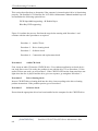
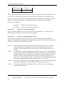
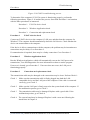
2.3
Power Supply Troubleshooting
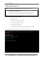
STA R T
C h e c k P o w e r S u p p ly
S ta tu s (P ro c e d u re 1 )
A re th e D C -IN
a n d B a tte ry L E D s
lit?
No
R e p la c e a d a p to r /
b a tte ry
(P ro c e d u re 2 )
Y es
R u n d ia g n o s tic
p ro g ra m
(P ro c e d u re 4 )
Y es
C h e c k p o w e r s u p p ly
c o n n e c tio n s
(P ro c ed u re 3 )
C a n y o u tu rn th e
c o m p u te r o n ?
No
A re th e in te rn a l
p o w e r c o n n e c tio n s
secu re?
No
P e rfo rm in te rn a l
c o n n e c tio n c h e c k
(P ro c e d u re 5 )
Y es
R e p la c e s y s te m b o a rd
EN D
[CONFIDENTIAL]
ual
Satellite L670/L675/ProL670 Series Maintenance Man
2 Troubleshooting
Procedures
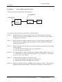
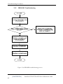
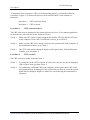
Figure 2-2 Power Supply Troubleshooting Process
The power supply controls many functions and components. To determine if the power
supply is functioning properly, start with Procedure 1 and continue with the other Procedures
as instructed. The flowchart in Figure 2-2 gives a summary of the process. The procedures
described in this section are:
Procedure 1: Power Status Check
Procedure 2: Adaptor / battery replacement
Procedure 3: Power supply connection check
Procedure 4: Diagnostic check
Procedure 5: Internal connection check
Procedure 1
Power Status Check
The following LEDS indicate the power supply status:
Battery LED
DC-IN LED
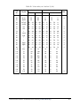
The power supply controller displays the power supply status through the Battery and the DCIN LEDS as listed in the tables below.
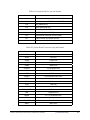
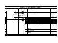
Table 2-1 Battery LED
Battery State
LED colors
Definition
Charging
Amber, solid on
Battery charging with AC.
White, solid on
Battery fully charged by AC
Amber color off
Battery abnormal stop charging with AC
(Bad cell/ Overheated)
Discharging
Amber, blinking
Battery within low state: 12 minutes
(LED on for 1 second remaining
every 4 seconds)
Amber, blinking
Battery within critical low state: 3
(LED on for 1 second minutes remaining. The system is
protected and cannot be re-powered on
every 2 seconds)
without the AC power connected.
Amber color off
Battery not in low or critical low state;
It’s in discharging state
Satellite L670/L675/ProL670 Series Maintenance Manual
[CONFIDENTIAL]
2-iii
2 Troubleshooting Procedures
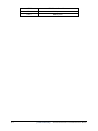
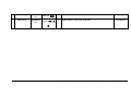
Table 2-2 DC-IN LED
AC-IN LED
Power supply status
Solid on
AC power exists (LED is solid White).
Off
No AC power exists.
To check the power supply status, install a battery pack and connect an AC adaptor to the
DC-IN port on the computer and to a power supply.
If the DC-IN LED or Battery LED is not lit, go to Procedure 2.
Procedure 2
Adaptor / battery replacement
A faulty adaptor may not supply power or may not charge the battery. Perform Check 1.
Check 1
Connect a new AC adaptor. If the problem is not resolved, go to Check 2.
Check 2
Insert a new battery. If the problem is still not resolved, go to Procedure 3.
[CONFIDENTIAL]
ual
Satellite L670/L675/ProL670 Series Maintenance Man
2 Troubleshooting
Procedures
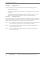
Procedure 3
Power supply connection check
The power supply wiring diagram is shown below:
AC adaptor cord
AC power cord
AC
adaptor
System
board
Battery
Any of the connectors may be disconnected. Perform Check 1.
Check 1
Disconnect the AC power cord from wall outlet. Check the power cable for
breaks. If the power cord is damaged, connect a new AC power cord. If there is
no damage, go to Check 2.
Check 2
Make sure the AC adaptor cord and AC power cord are firmly plugged into the
DC-IN socket, AC adaptor inlet and wall outlet. If these cables are connected
correctly, go to Check 3.
Check 3
Make sure that the DC-IN input port socket is firmly secured to the system board
of the computer.
• If the DC-IN input socket is loose, go to Procedure 5.
• If it is not loose, go to Check 4.
Check 4
Use a multi-meter to make sure that the AC adaptor output voltage is close to 19
V. If the output is several percent lower than 19 V, go to Check 5. If the output
is close to 19 V, go to Check 6.
Check 5
Connect a new AC adaptor or AC power cord.
• If the DC-IN LED does not light, go to Procedure 4.
• If the battery LED does not light, go to Check 6.
Check 6
Make sure the battery pack is installed in the computer correctly. If the battery is
properly installed and the battery LED still does not light, go to Procedure 4.
Satellite L670/L675/ProL670 Series Maintenance Manual
[CONFIDENTIAL]
2-iii
2 Troubleshooting Procedures
Procedure 4
Diagnostic check
The power supply may not charge the battery pack. Perform the following procedures:
1. Reinstall the battery pack.
2. Attach the AC adaptor and turn on the power. If you cannot turn on the power, go to
Procedure 5.
3. Run the Diagnostic test following the procedures described in Chapter 3, Tests and
Diagnostics. If no problem is detected, the battery is functioning normally.
Procedure 5
Replacement check
The system board may be disconnected or damaged. Disassemble the computer following the
steps described in Chapter 4, Replacement Procedures. Check the connection between the AC
adaptor and the system board. After checking the connection, perform Check 1:
Check 1
Use a multimeter to make sure that the fuses on the system board are not blown. If
a fuse is not blown, go to Check 2. If a fuse is blown, go to Check 3.
Check 2
Make sure that the battery cable is firmly connected to the system board. If it is
connected firmly, go to Check 3.
Check 3
The system board may be damaged. Replace it with a new one following the
instructions in Chapter 4.
[CONFIDENTIAL]
ual
Satellite L670/L675/ProL670 Series Maintenance Man
2 Troubleshooting
Procedures
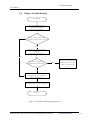
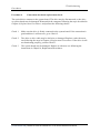
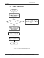
2.4
Display Troubleshooting
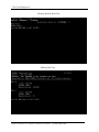
START
P e rfo rm e x te rn a l
d is p la y c h e c k
(P ro ce d u re 1 )
D o e s th e e x te rn a l
d is p la y fu n c tio n o k ?
No
P e rfo rm d ia g n o s tic
check
(P ro ce d u re 2 )
Y es
W a s a d is p la y
p ro b le m d e te c te d ?
No
D is p la y is n o t
fa u lty . C o n tin u e
tro u b le s h o o tin g
-re fe r to F ig u re
2 -1
Y es
P e rfo rm c o n n e c to r a n d
re p la c e m e n t c h e c k
(P ro ce d u re 3 )
R e p la c e s y s te m b o a rd
END
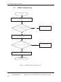
Figure 2-3 Display troubleshooting process
Satellite L670/L675/ProL670 Series Maintenance Manual
[CONFIDENTIAL]
2-iii
2 Troubleshooting Procedures
This section describes how to determine if the computer’s display is functioning properly.
The process is outlined in Figure 2-3. Start with Procedure 1 and continue with the other
procedures as instructed.
Procedure 1: External display check
Procedure 2: Diagnostic check
Procedure 3: Connector and replacement check
Procedure 1
External display check
Connect an external display to the computer’s external monitor port, and then boot the
computer. The computer automatically detects the external display.
If the external display works correctly, the internal LCD may be damaged. Go to Procedure 3.
If the external monitor appears to have the same problem as the internal monitor, the system
board may be damaged. Go to Procedure 2.
Procedure 2
Diagnostic check
The Display Test program is stored on the computer’s Diagnostics disk. This program checks
the display controller on the system board. Insert the Diagnostics disk in the computer’s
floppy disk drive, turn on the computer and run the test. Refer to Chapter 3, Tests and
Diagnostics for details.
If an error is detected, go to Procedure 3. If an error is not detected, the display is functioning
properly.
[CONFIDENTIAL]
ual
Satellite L670/L675/ProL670 Series Maintenance Man
2 Troubleshooting
Procedures
Procedure 3
Connector and replacement check
The LCD module and system board are connected to the display circuits. Any of these
components may be damaged. Refer to Chapter 4, Replacement Procedures, for instructions
on how to disassemble the computer and then perform the following checks:
Check 1
Make sure the DDR3 RAM module is seated properly. Test display again. If the
problem still exits, replace the DDR RAM module. If the problem still exists,
perform Check 2.
Check 2
Replace the LCD module with a new one and test display again. If the problem
still exists, perform Check 3.
Check 3
Replace the LCD/FL cable with a new one and test display again. If the problem
still exists, perform Check 4.
Check 4
Replace the CPU with another of the same specifications. If the problem still
exists, perform Check 5.
Check 5
The system board may be damaged. Replace it with a new one.
Satellite L670/L675/ProL670 Series Maintenance Manual
[CONFIDENTIAL]
2-iii
2 Troubleshooting Procedures
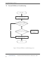
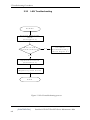
2.5
Keyboard Troubleshooting
STA R T
P e rfo rm d ia g n o s tic
check
(P ro ced u re 2 )
W as a k ey b o ard
p ro b le m d e te c te d ?
N o
K e y b o a rd is n o t
fa u lty . C o n tin u e
tro u b le s h o o tin g re fe r to F ig u re 2 -1
Y es
P e rfo rm c o n n e c to r a n d
re p la c e m e n t c h e c k
(P ro ced u re 3 )
R e p la c e s y s te m b o a rd
EN D
[CONFIDENTIAL]
ual
Satellite L670/L675/ProL670 Series Maintenance Man
2 Troubleshooting
Procedures
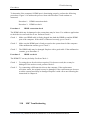
Figure 2-4 Keyboard troubleshooting process
To determine if the computer’s internal keyboard is functioning properly, perform the
following procedures. Figure 2-4 outlines the process. Start with Procedure 1 and continue
with the other procedures as instructed.
Procedure 1: Diagnostic check
Procedure 2: Connector and replacement check
Procedure 1
Diagnostic check
Run the test and Diagnostics Program, which will automatically execute the Keyboard Test.
Refer to Chapter 3, Tests and Diagnostics for more information on how to run the program.
If an error is located, go to Procedure 2. If an error does not occur, the keyboard is
functioning ok.
Procedure 2
Connector and replacement check
The keyboard and/or system board may be disconnected or damaged. Disassemble the
computer following the steps described in Chapter 4, Replacement Procedures and perform
the following checks.
Check 1
Make sure the keyboard cable is firmly connected to the system board.
If the connection is loose, reconnect firmly and repeat Procedure 2. If there is still
an error, go to Check 2.
Check 2
The keyboard may be damaged. Replace it with a new one following the
instructions in Chapter 4.
If the problem still exists, perform Check 3.
Check 3
The system board may be damaged. Replace it with a new one following the
instructions in Chapter 4.
Satellite L670/L675/ProL670 Series Maintenance Manual
[CONFIDENTIAL]
2-iii
2 Troubleshooting Procedures
2.6
External USB Devices Troubleshooting
STA RT
P e rfo rm e x te rn a l d e v ic e
a n d c o n n e c tio n c h e c k
(P ro c e d u re 1 )
D o e s th e d e v ic e fu n c tio n
c o rre c tly w h e n
c o n n e c te d to a d iffe re n t
U S B p o rt?
No
Y es
D o e s a n a lte rn a tiv e U S B
d e v ic e fu n c tio n c o rre c tly ?
Y es
O rig in a l U S B
d e v ic e is
fa u lty
No
R e p la c e s y s te m b o a rd
(P ro c e d u re 2 )
EN D
Figure 2-5 External USB device troubleshooting process
[CONFIDENTIAL]
ual
Satellite L670/L675/ProL670 Series Maintenance Man
2 Troubleshooting
Procedures
To determine if the computer’s external USB devices are functioning properly, perform the
following procedures. Figure 2-5 outlines the process. Start with Procedure 1 and continue as
instructed.
Procedure 1: External device and connection check
Procedure 2: Replace system board
Procedure 1
External device and connection check
The USB device may be damaged or the connection may be faulty. Use windows application
to check device can work fine or not. If an error is located, go to Perform Check 1. If an error
does not occur, the USB is functioning ok.
Check 1
Make sure USB device cable is firmly plugged into one of the USB sockets. If the
cable is connected correctly, go to Check 2.
Check 2
Plug the USB device into another USB socket (there are three in all). If the USB
device still does not work, go to Check 4.
If the device functions correctly when connected to another USB port, go to
Check 3.
Check 3
Make sure that the USB socket is firmly secured to the system board of the
computer. If the malfunction remains, the system board or USB small board may
be damaged. Go to Procedure 2.
Check 4
Connect an alternative USB device to one of the computer’s USB ports, and then
boot the computer. The computer automatically detects the external device.
If the alternative USB device works correctly, the original device may be
damaged and should be replaced.
If the alternative USB device appears to have the same problem as the original
device, the system board or USB small board may be damaged. Go to Procedure
2.
Procedure 2
Replace system board
If the error persists, the system board or USB small board may be damaged. Replace it with a
new one following the instructions in Chapter 4.
Satellite L670/L675/ProL670 Series Maintenance Manual
[CONFIDENTIAL]
2-iii
2 Troubleshooting Procedures
2.7
Touch Pad Troubleshooting
START
P e rfo rm d ia g n o s tic
check
(P ro ce d u re 1 )
D oes T ouchpad
fu n c tio n o k ?
No
P e rfo rm d ia g n o s tic
check
(P ro ce d u re 2 )
Y es
W as a T ouchpad
p ro b le m d e te c te d ?
No
T o u c h p a d is n o t
fa u lty . C o n tin u e
tro u b le s h o o tin g
-re fe r to F ig u re
2 -1
Y es
P e rfo rm c o n n e c to r a n d
re p la c e m e n t c h e c k
(P ro ce d u re 3 )
R e p la c e s y s te m b o a rd
END
[CONFIDENTIAL]
ual
Satellite L670/L675/ProL670 Series Maintenance Man
2 Troubleshooting
Procedures
Figure 2-6 Touchpad troubleshooting process
Satellite L670/L675/ProL670 Series Maintenance Manual
[CONFIDENTIAL]
2-iii
2 Troubleshooting Procedures
To determine if the computer’s built-in Touchpad is functioning properly, perform the
following procedures. Figure 2-6 outlines the process. Start with Procedure 1 and continue as
instructed.
Procedure 1: Diagnostic test
Procedure 2: Touchpad connection check
Procedure 3: Touchpad replacement check
Procedure 1
Diagnostic test
Run the Diagnostic Program, which will automatically execute the Touchpad test. (Refer to
Chapter 3 system configuration check), Tests and Diagnostics for more information on the
program.
If an error is located, go to Procedure 2. If an error is not located, the Touchpad function is
functioning properly.
Procedure 2
Touchpad connection check
The Touchpad is connected via the Touchpad FPC to the system board. Make sure the
Touchpad FPC cable is firmly connected to the Touchpad and system board. Refer to Chapter
4, Replacement Procedures, for instructions on how to disassemble the computer and then
perform the following checks.
If any of the connections are loose, reconnect firmly. If any of the connections is damaged, or
there is still an error, go to Procedure 3.
Procedure 3
Touchpad replacement check
The Touchpad unit or FPC may be defective or damaged. Replace each with a new one
following the steps in Chapter 4. If the free-Dos test is still not functioning properly, replace
the system board with a new one following the steps in Chapter 4.
[CONFIDENTIAL]
ual
Satellite L670/L675/ProL670 Series Maintenance Man
2 Troubleshooting
Procedures
2.8
Speaker Troubleshooting
START
P e rfo rm a u d io s o u rc e te s t
(P ro c e d u re 1 )
D o a ll s o u rc e s h a v e
s a m e p ro b le m ?
No
S p e ak ers are n o t
fa u lty . C o n tin u e
tro u b le s h o o tin g s e e F ig u re 2 -1
Y es
P e rfo rm e a rp h o n e te s t
(P ro c e d u re 2 )
D o e arp h o n e s
fu n c tio n c o rre c tly ?
Y es
No
P e rfo rm c o n n e c tio n c h e c k
(P ro c e d u re 3 )
P e rfo rm re p la c e m e n t
check
(P ro c e d u re 4 )
R e p la c e s y s te m b o a rd
END
Figure 2-7 Speaker troubleshooting process
[CONFIDENTIAL] Satellite A130/A135 /Satellite Pro A130 Series Maintenance Manua
2 Troubleshooting Procedures
To determine if the computer’s built-in speakers are functioning properly, perform the
following procedures. Figure 2-7 outlines the process. First adjust the speaker volume to an
appropriate level. Start with Procedure 1 and continue as instructed.
Procedure 1: Audio source test
Procedure 2: Earphone test
Procedure 3: Connection check
Procedure 4: Replacement check
Procedure 1
Audio source test
Try different audio sources (e.g. an audio CD and digital music file) to determine whether the
fault is in the speaker system or not. If not all sources have sound problem, the problem is in
the source devices. If all have the same problem, continue with Procedure 2.
Procedure 2
Earphone test
Connect a set if earphones or external speakers. If these function correctly, go to Procedure 3.
If they do not function correctly, the system board may be defective or damaged. Replace it
with a new one.
Procedure 3
Connection check
Disassemble the computer following the steps described in Chapter 4, Replacement
Procedures and make sure the speaker cable is firmly connected to the audio board. If the
stereo speakers are still not functioning properly, go to Procedure 4.
Procedure 4
Replacement check
If the stereo speakers don't sound properly, the stereo speakers may be defective or damaged.
Replace them with new ones. If the stereo speakers still do not work properly, try replacing in
turn the audio board and system board.
[CONFIDENTIAL]
ual
Satellite L670/L675/ProL670 Series Maintenance Man
2 Troubleshooting
Procedures
2.9
Optical Drive Troubleshooting
START
P e rfo rm a u d io C D c h e c k
(P ro c e d u re 1 )
A u d io C D fu n c tio n s o k ?
No
P e rfo rm d riv e c le a n in g c h e c k
(P ro c e d u re 2 )
Y es
P e rfo rm so ftw a re c h e c k
(P ro c e d u re 3 )
P e rfo rm d ia g n o s tic te s t
(P ro c e d u re 4 )
P e rfo rm c o n n e c tio n a n d
re p la c e m e n t c h e c k
(P ro c e d u re 5 )
R e p la c e s y s te m b o a rd
END
Figure 2-8 Optical drive troubleshooting process
[CONFIDENTIAL] Satellite A130/A135 /Satellite Pro A130 Series Maintenance Manua
2 Troubleshooting Procedures
This section describes how to determine if the computer’s internal optical drive is functioning
properly. The Satellite L670/ Satellite Pro L670 Series Maintenance Manual module bays can
accommodate the following optical drives:
DVD SuperMulti supporting +-R Double Rayer
Blue-Ray DVD supporting
Figure 2-8 outlines the process. Perform the steps below starting with Procedure 1 and
continue with the other procedures as required.
Procedure 1: Audio CD test
Procedure 2: Drive cleaning check
Procedure 3: Software check
Procedure 4: Connection and replacement check
Procedure 1
Audio CD check
First, insert an audio CD into the CD/DVD drive. Use windows application to check device
can work fine or not. If it works, the problem is not with the drive. Go to Procedure 3. If the
audio CD does not work, go to Procedure 2. If the CD/DVD LED on the front panel does not
light when the disc is played and the drive gives no response, go straight to Procedure 3.
Procedure 2
Drive cleaning check
Insert a CD/DVD drive-cleaning disk into the drive clean according to the drive-cleaning
product instructions. If the problem persists, go to Procedure 3.
Procedure 3
Software check
Ensure that the appropriate driver has been installed on the computer for the CD/DVD drive.
[CONFIDENTIAL]
ual
Satellite L670/L675/ProL670 Series Maintenance Man
2 Troubleshooting
Procedures
Procedure 4
Connection check and replacement check
The optical drive connects to the system board. The drive may be disconnected, or the drive
or system board may be damaged. Disassemble the computer following the steps described in
Chapter 4, Replacement Procedures, and perform the following checks:
Check 1
Make sure the drive is firmly connected to the system board. If the connection is
good and there is still an error, go to Check 2.
Check 2
The drive or drive cable may be defective or damaged. Replace each with a new
one following the steps in Chapter 4, Replacement Procedures. If the drive is still
not functioning properly, perform Check 3.
Check 3
The system board may be damaged. Replace it with new one following the
instructions in Chapter 4, Replacement Procedures.
[CONFIDENTIAL] Satellite A130/A135 /Satellite Pro A130 Series Maintenance Manua
2 Troubleshooting Procedures
2.10 Modem Troubleshooting
START
P e r f o r m te le p h o n e lin e
c o n n e c tio n c h e c k
(P ro c e d u re 1 )
C o m p u te r u n a b le to
d e te c t te le p h o n e s ig n a l?
Y es
C h e c k / r e p la c e
te le p h o n e lin e a n d
c o n n e c tio n s
No
P e r f o r m c o n n e c tio n c h e c k
(P ro c e d u re 2 )
P e r f o r m r e p la c e m e n t
check
(P ro c e d u re 3 )
R e p la c e s y s te m b o a r d
END
[CONFIDENTIAL]
ual
Satellite L670/L675/ProL670 Series Maintenance Man
2 Troubleshooting
Procedures
Figure 2-9 Modem troubleshooting process
[CONFIDENTIAL] Satellite A130/A135 /Satellite Pro A130 Series Maintenance Manua
2 Troubleshooting Procedures
This section describes how to determine if the computer’s modem is functioning properly.
Figure 2-9 outlines the process. Perform the steps below starting with Procedure 1 and
continuing with the other procedures as required.
Procedure 1: Telephone line connection check
Procedure 2: Modem card connection check
Procedure 3: Modem card replacement check
Procedure 1
Telephone line connection check
The telephone cable may be damaged or the connections may be loose. Use windows
application to check device can work fine or not. Attempt to connect the computer to a
network through using the modem. If the modem does not function at all, go to Procedure 3.
If the attempt fails because the computer detects no telephone signal, the fault may be in the
telephone cable, the wall socket or the modem port. Perform Check 1:
Check 1
Make sure telephone cable is firmly plugged into both the telephone wall socket
and the modem port of the computer. If the cable is connected correctly, go to
Check 2.
Check 2
Make sure the modem port is firmly secured to the system board of the computer.
If the malfunction remains, go to Check 3.
Check 3
The telephone cable may be damaged. Replace with a good cable. If the
malfunction remains, go to Procedure 2.
Procedure 2
Modem card connection check
Disassemble the computer following the steps described in Chapter 4, Replacement
Procedures and ensure that the modem card is well connected to the system board. If the
problem persists, perform Procedure 3.
Procedure 3
Modem replacement check
The modem card or RJ-11 jack may be faulty. Try replacing them. If the problem persists, the
system board may be defective or damaged. Replace the System Board with a new one
following the steps in Chapter 4, Replacement Procedures.
[CONFIDENTIAL]
ual
Satellite L670/L675/ProL670 Series Maintenance Man
2 Troubleshooting
Procedures
2.11
Wireless LAN Troubleshooting
START
Perform Wireless LAN connection check
(Procedure 1)
Was a wireless LAN problem delected?
No
Wireless LAN system
is not faulty. Continue
troubleshooting - refer
to Figure 2-1
Yes
Perform connector and replacement check
(Procedure 2)
Replace wireless LAN antenna/unit
Replace system board
END
Figure 2-10 Wireless LAN troubleshooting process
Notes: W/L Antenna assemble rule as below:
color of antenna Assemble location
[CONFIDENTIAL] Satellite A130/A135 /Satellite Pro A130 Series Maintenance Manua
2 Troubleshooting Procedures
White antenna
Main/1
Black antenna
Aux/2
The wireless LAN antenna wire, wireless LAN unit or system board may each be the source
of a wireless LAN fault. Any of these components may be damaged. To determine if the
computer’s wireless LAN system is functioning properly, perform the following procedures.
Figure 2-10 outlines the process. Start with Procedure 1 and continue with the other
procedures as instructed.
Procedure 1: Wireless LAN connection test
Procedure 2: Connector and replacement check
Procedure 1
Wireless LAN connection check
PLS use windows application. If an error is located, go to Procedure 2. If an error is not
located, the wireless LAN system is functioning properly.
Procedure 2
Connector and replacement check
The wireless LAN antenna, wireless LAN unit or system board may be disconnected or
damaged. Disassemble the computer following the steps described in Chapter 4, Replacement
Procedures, and perform the following checks.
Check 1
Make sure that the wireless LAN antenna is firmly connected to the Wireless
LAN module (refer to Chapter 4 for instructions) and that the wireless LAN
module is securely slotted into the system board. If the problem persists, go to
Check 2.
Check 2
Check that the wireless communication switch is turned to “On”, and then make
sure that the wireless communication LED on the front panel is light. If the LED
is light but the wireless LAN function is still faulty, the antenna may be damaged.
Replace with a new antenna following the steps in Chapter 4, Replacement
Procedures. If the problem persists, or if the wireless LAN LED is not light when
the wireless communication switch is turned to “On”, go to Check 3.
Check 3
The wireless LAN unit may be damaged. Replace it with a new one following the
instructions in Chapter 4. If the problem still exists, perform Check 4.
Check 4
The system board may be damaged. Replace it with a new one following the
instructions in Chapter 4.
[CONFIDENTIAL]
ual
Satellite L670/L675/ProL670 Series Maintenance Man
2 Troubleshooting
Procedures
2.12
Camera Troubleshooting
Figure 2-11 Camera troubleshooting process
[CONFIDENTIAL] Satellite A130/A135 /Satellite Pro A130 Series Maintenance Manua
2 Troubleshooting Procedures
The Camera board or system board may be the reason of a Camera fault. Either of these two
components may be damaged. To determine if the computer’s Camera is functioning
properly, perform the following procedures. Figure 2-11 outlines the process. Start with
Procedure 1 and continue with the other procedures as instructed.
Procedure 1: Windows Application test
Procedure 2: Connector and replacement check
Procedure 1
Windows Application test
Run the functioning Program in windows, which will display the Camera test result.
If tests and diagnostics result abnormal go to Procedure 2. If an error is not located, the
Camera system is functioning properly.
Procedure 2
Connector and replacement check
The Camera board or system board may be disconnected or damaged. Disassemble the
computer following the steps described in Chapter 4, Replacement Procedures, and perform
the following checks.
Check 1
Make sure that the Camera board cable is securely slotted into the system board.
If the problem persists, go to Check 2.
Check 2
The Camera board may be damaged. Replace it with a new one following the
instructions in Chapter 4. If the problem still exists, perform Check 3.
Check 3
The system board may be damaged. Replace it with a new one following the
instructions in Chapter 4.
[CONFIDENTIAL]
ual
Satellite L670/L675/ProL670 Series Maintenance Man
2 Troubleshooting
Procedures
2.13
Bluetooth Troubleshooting
Figure 2-12 Bluetooth troubleshooting process
[CONFIDENTIAL] Satellite A130/A135 /Satellite Pro A130 Series Maintenance Manua
2 Troubleshooting Procedures
The Bluetooth antenna wire, Bluetooth module or system board may be the reason of a
Bluetooth fault. Any of these components may be damaged. To determine if the computer’s
Bluetooth is functioning properly, perform the following procedures. Figure 2-12 outlines the
process. Start with Procedure 1 and continue with the other procedures as instructed.
Procedure 1: Windows Application test
Procedure 2: Connector and replacement check
Procedure 1
Windows Application test
PLS use windows application to check device can work fine or not. If an error is located, go
to Procedure 2. If an error is not located, the Bluetooth system is functioning properly.
Procedure 2
Connector and replacement check
The Bluetooth, antenna module or system board may be disconnected or damaged.
Disassemble the computer following the steps described in Chapter 4, Replacement
Procedures, and perform the following checks.
Check 1
Make sure that the Bluetooth antenna is firmly connected to the Bluetooth module
(refer to Chapter 4 for instructions) and that the Bluetooth FFC is securely slotted
into the system board. If the problem persists, go to Check 2.
Check 2
Check that the Bluetooth communication switch is turned to “On”, then make sure
that the communication LED on the left panel is lit. If the LED is lit but the
Bluetooth function is still faulty, the antenna module may be damaged. Replace
with a new antenna following the steps in Chapter 4, Replacement Procedures. If
the problem persists, or if the Bluetooth communication LED is not lit when the
Bluetooth communication switch is turned to “On”, go to Check 3.
Check 3
The Bluetooth module may be damaged. Replace it with a new one following the
instructions in Chapter 4. If the problem still exists, perform Check 4.
Check 4
The system board may be damaged. Replace it with a new one following the
instructions in Chapter 4.
[CONFIDENTIAL]
ual
Satellite L670/L675/ProL670 Series Maintenance Man
2 Troubleshooting
Procedures
2.14 Bridge Media Slot Troubleshooting
START
Perform Bridge Media Slot test
(Procedure 1)
Do errors occur during
Bridge Media Slot test?
No
Bridge Media Slot
unit is not faulty.
Yes
Bridge Media Slot socket
replacement check
(Procedure 2)
Replace system board
END
Figure 2-13 Bridge Media Slot troubleshooting process
[CONFIDENTIAL] Satellite A130/A135 /Satellite Pro A130 Series Maintenance Manua
2 Troubleshooting Procedures
This section describes how to determine if the Bridge Media Slot player is functioning
properly. The process is summarized in Figure 2-13. Perform the steps below starting with
Procedure 1 and continuing with the other procedures as required.
Procedure 1: Bridge Media Slot test
Procedure 2: Bridge Media Slot replacement check
Procedure 1
Bridge Media Slot test
The Bridge Media Slot test PLS Use windows application to check device can work fine or
not. Ensure the card in fully inserted into the socket before running the program.
If an error occurs during the Bridge Media Slot test, perform Procedure 2. If no error occurs,
it is likely that the original Bridge Media Slot was faulty.
Procedure 2
Bridge Media Slot socket replacement check
The Bridge Media Slot socket may be damaged or defective, for instance the socket pins can
be bent. Disassemble the computer following the steps described in Chapter 4, Replacement
Procedures and replace the socket. If the problem persists, the system board may be defective
or damaged. Replace the system board with a new one following the steps in Chapter 4.
[CONFIDENTIAL]
ual
Satellite L670/L675/ProL670 Series Maintenance Man
2 Troubleshooting
Procedures
[CONFIDENTIAL] Satellite A130/A135 /Satellite Pro A130 Series Maintenance Manua
2 Troubleshooting Procedures
2.15
HDD/SSD Troubleshooting
Figure 2-14 HDD/SDD troubleshooting process
[CONFIDENTIAL]
ual
Satellite L670/L675/ProL670 Series Maintenance Man
2 Troubleshooting
Procedures
The HDD/SSD or system board may be the reason of a HDD/SSD fault. Either of these two
components may be damaged. To determine if the computer’s HDD/SDD is functioning
properly, perform the following procedures. Figure 2-14 outlines the process. Start with
Procedure 1 and continue with the other procedures as instructed.
Procedure 1: Diagnostic test
Procedure 2: Connector and replacement check
Procedure 1
Diagnostic test
Run the Diagnostic Program, which will automatically execute the HDD/SSD R/W test.
(Refer to Chapter 3 system configuration check), Tests and Diagnostics for more information
on the program.
If an error is located, go to Procedure 2. If an error is not located, the HDD/SSD function is
functioning properly.
Procedure 2
Connector and replacement check
The HDD module or system board may be disconnected or damaged. Disassemble the
computer following the steps described in Chapter 4, Replacement Procedures, and perform
the following checks.
Check 1
Make sure that the HDD module is securely slotted into the system board. If the
problem persists, go to Check 2.
Check 2
The HDD module may be damaged. Replace it with a new one following the
instructions in Chapter 4. If the problem still exists, perform Check 3.
Check 3
The system board may be damaged. Replace it with a new one following the
instructions in Chapter 4.
[CONFIDENTIAL] Satellite A130/A135 /Satellite Pro A130 Series Maintenance Manua
2 Troubleshooting Procedures
2.16
CRT Troubleshooting
S T A R T
P e rfo rm
C R T c o n n e c tio n c h e c k
(P ro c e d u re 1 )
D o e s re p la c e m e n t
C R T c a b le
fu n c tio n p ro p e rly ?
N o
R e p la c e C R T
c a b le
N o
U s e d iffe re n t
C R T set
Y es
P e rfo rm C R T se t c h e c k
(P ro c e d u re 2 )
C R T fu n c tio n in g o k ?
Y es
R e p la c e s y s te m
b o a rd
C heck C R T
P o rt
c o n n e c tio n
E N D
Figure 2-15 CRT troubleshooting process
[CONFIDENTIAL]
ual
Satellite L670/L675/ProL670 Series Maintenance Man
2 Troubleshooting
Procedures
To determine if the computer’s CRT port is functioning properly, perform the following
procedures. Figure 2-15 outlines the process. Start with Procedure 1 and continue as
instructed.
Procedure 1: CRT connection check
Procedure 2: CRT set check
Procedure 1
CRT connection check
The CRT cable may be damaged or the connections may be loose. Use windows application
to check device can work fine or not. Perform Check 1:
Check 1
Make sure CRT cable is firmly plugged into both the CRT set and the CRT port
of the computer. If the cable is connected correctly, go to Check 2.
Check 2
Make sure the CRT port is firmly secured to the system board of the computer. If
the malfunction remains, go to Check 3.
Check 3
The CRT cable may be damaged. Replace with a good cable. If the malfunction
remains, go to Procedure 2.
Procedure 2
CRT set check
The CRT set may be faulty. Perform Check 1:
Check 1
Try using the set for CRT reception. If it does not work, the set may be damaged.
If the set does work, perform Check 2.
Check 2
Try connecting a different CRT to the computer. If the replacement CRT works,
the original set may be damaged. If the replacement set does not work the system
board may be damaged. Replace it with a new one following the instructions in
Chapter 4.
[CONFIDENTIAL] Satellite A130/A135 /Satellite Pro A130 Series Maintenance Manua
2 Troubleshooting Procedures
2.17
HDMI Troubleshooting
S T A R T
P e rfo rm
H D M I c o n n e c tio n
check
(P ro c e d u re 1 )
D o e s re p la c e m e n t H D M I
c a b le
fu n c tio n p ro p e rly ?
N o
R e p la c e H D M I
c a b le
N o
U s e d iffe re n t
H D M I set
Y es
P e rfo rm H D M I se t c h e c k
(P ro c e d u re 2 )
H D M I fu n c tio n in g o k ?
Y es
R e p la c e s y s te m
b o a rd
E N D
Figure 2-16 HDMI troubleshooting process
[CONFIDENTIAL]
ual
Satellite L670/L675/ProL670 Series Maintenance Man
2 Troubleshooting
Procedures
To determine if the computer’s HDMI port is functioning properly, perform the following
procedures. Figure 2-16 outlines the process. Start with Procedure 1 and continue as
instructed.
Procedure 1: HDMI connection check
Procedure 2: HDMI set check
Procedure 1
HDMI connection check
The HDMI cable may be damaged or the connections may be loose. Use windows application
to check device can work fine or not. Perform Check 1:
Check 1
Make sure HDMI cable is firmly plugged into both the HDMI set and the HDMI
port of the computer. If the cable is connected correctly, go to Check 2.
Check 2
Make sure the HDMI port is firmly secured to the system board of the computer.
If the malfunction remains, go to Check 3.
Check 3
The HDMI cable may be damaged. Replace with a good cable. If the malfunction
remains, go to Procedure 2.
Procedure 2
HDMI set check
The HDMI TV set may be faulty. Perform Check 1:
Check 1
Try using the set for television reception. If it does not work, the set may be
damaged. If the set does work, perform Check 2.
Check 2
Try connecting a different television to the computer. If the replacement
television works, the original set may be damaged. If the replacement set does not
work the system board may be damaged. Replace it with a new one following the
instructions in Chapter 4.
2.18
MIC Troubleshooting
[CONFIDENTIAL] Satellite A130/A135 /Satellite Pro A130 Series Maintenance Manua
2 Troubleshooting Procedures
Figure 2-17 MIC troubleshooting process
[CONFIDENTIAL]
ual
Satellite L670/L675/ProL670 Series Maintenance Man
2 Troubleshooting
Procedures
The MIC line or system board may be the reason of a MIC fault. Either of these two
components may be damaged. To determine if the computer’s MIC is functioning properly,
perform the following procedures. Figure 2-17 outlines the process. Start with Procedure 1
and continue with the other procedures as instructed.
Procedure 1: Windows Application test
Procedure 2: Connector and replacement check
Procedure 1
Windows Application test
Run the functioning Program (record.exe) on Windows model, which will display the MIC
test result.
If tests and diagnostics result abnormal go to Procedure 2. If an error is not located, the MIC
module functioning is properly.
Procedure 2
Connector and replacement check
The MIC line or system board may be disconnected or damaged. Disassemble the computer
following the steps described in Chapter 4, Replacement Procedures, and perform the
following checks.
Check 1
Make sure that the MIC line is securely slotted into the system board. If the
problem remains, go to Check 2.
Check 2
The MIC line may be damaged. Replace it with a new one following the
instructions in Chapter 4. If the problem still exists, perform Check 3.
Check 3
The system board may be damaged. Replace it with a new one following the
instructions in Chapter 4.
[CONFIDENTIAL] Satellite A130/A135 /Satellite Pro A130 Series Maintenance Manua
2 Troubleshooting Procedures
2.19
E-SATA Troubleshooting
START
Perform E-SATA device check
(Procedure 1)
Is E-SATA transmission ok?
Yes
Perform function check
(Procedure 2)
No
Was an E-SATA problem detected?
No
E-SATA port and
transmission are not
faulty. Continue
troubleshooting - refer
to Figure 2-1
Yes
Perform connection and replacement check
(Procedure 3)
Replace system board
END
[CONFIDENTIAL]
ual
Satellite L670/L675/ProL670 Series Maintenance Man
2 Troubleshooting
Procedures
Figure 2-18 E-SATA troubleshooting process
To determine if the computer’s E-SATA system is functioning properly, perform the
following procedures. Figure 2-18 outlines the process. Start with Procedure 1 and continue
with the other procedures as instructed.
Procedure 1: E-SATA device check
Procedure 2: Windows Application check
Procedure 3: Connection and replacement check
Procedure 1
E-SATA device check
Connect an E-SATA device to the computer’s LAN port, and then boot the computer for
Windows7. The computer should automatically detect the LAN device. Check whether the
device can transmit data to the computer.
If the device is able to communicate with the computer, the problem may be intermittent or
connections may be faulty. Go to Procedure 2.
If communication is impaired, there may be a faulty connection. Go to Procedure 3.
Procedure 2
Windows Application check
Run the Windows Application, which will automatically execute the LAN port test for
transmission, Tests and Diagnostics for more information on how to run the program.
If an error is located, go to Procedure 3. If an error does not occur, the LAN port is
functioning properly.
Procedure 3
Connection and replacement check
The transmission cable may be damaged or the connections may be loose. Perform Check 1:
Check 1
Make sure the transmission cable is firmly plugged into both the LAN compatible device and the LAN port of the computer. If the cable is connected
correctly, go to Check 2.
Check 2
Make sure the LAN port is firmly secured to the system board of the computer. If
the malfunction persists, go to Check 3.
Check 3
The transmission cable may be damaged. Replace with a good cable. If the
malfunction persists, go to Check 4
Check 4
The system board may be damaged. Replace it with a new one following the
instructions in Chapter 4.
[CONFIDENTIAL] Satellite A130/A135 /Satellite Pro A130 Series Maintenance Manua
2 Troubleshooting Procedures
2.20
LAN Troubleshooting
STA R T
P e rfo rm d ia g n o s tic
check
(P ro ced u re 2 )
W as a L A N
p ro b le m d e te c te d ?
N o
L A N is n o t fa u lty .
C o n tin u e
tro u b le s h o o tin g re fe r to F ig u re 2 -1
Y es
P e rfo rm c o n n e c to r a n d
re p la c e m e n t c h e c k
(P ro ced u re 3 )
R e p la c e s y s te m b o a rd
EN D
Figure 2-19 LAN troubleshooting process
[CONFIDENTIAL]
ual
Satellite L670/L675/ProL670 Series Maintenance Man
2 Troubleshooting
Procedures
To determine if the computer’s LAN port is functioning properly, perform the following
procedures. Figure 2-19 outlines the process. Start with Procedure 1 and continue as
instructed.
Procedure 1: Diagnostic check
Procedure 2: Connector and replacement check
Procedure 1
Diagnostic check
Run the test and Diagnostics Program, which will automatically execute the LAN Test.
Refer to Chapter 3, Tests and Diagnostics for more information on how to run the program.
If an error is located, go to Procedure 2. If an error does not occur, the LAN is functioning
ok.
Procedure 2
Connector and replacement check
The LAN cable and/or system board may be disconnected or damaged. Disassemble the
computer following the steps described in Chapter 4, Replacement Procedures and perform
the following checks.
Check 1
Make sure the LAN cable is firmly connected to the LAN port of the system
board.
If the connection is loose, reconnect firmly and repeat Procedure 2. If there is still
an error, go to Check 2.
Check 2
The LAN cable may be damaged. Replace it with a new one and repeat Procedure
2. If the problem still exists, perform Check 3.
Check 3
The system board may be damaged. Replace it with a new one following the
instructions in Chapter 4.
[CONFIDENTIAL] Satellite A130/A135 /Satellite Pro A130 Series Maintenance Manua
3 Tests and Diagnostics
Chapter 3
Tests and Diagnostics
Satellite L670/L675 / Pro L670 Series Maintenance Manual
[CONFIDENTIAL]
1
3 Tests and Diagnostics
Contents
3.1
The Diagnostic Test ............................................................................................................ 3
3.2
Executing the Diagnostic Test ............................................................................................ 4
3.3
Display Configuration ........................................................................................................ 8
3.4
Audio Sound Test ............................................................................................................... 8
3.5
Fan ON/OFF Test ............................................................................................................. 11
3.6
Main Battery Charge Test ................................................................................................. 13
3.7
FDD Test....................................................................................................................... …15
3.8
Memory Check.................................................................................................................. 16
3.9
Keyboard Test ................................................................................................................... 19
3.10
Mouse (Pad) Test .............................................................................................................. 21
3.11
LCD Pixels Mode Test ..................................................................................................... 22
3.12
Magnetic Switch Test ....................................................................................................... 23
3.13
LAN Test .......................................................................................................................... 25
3.14
RTC Test ........................................................................................................................... 27
3.15
1st HDDTest ……………………………....……….…….……………....….……….......28
3.16
Read DMI Test………………...….………………….………………...…..……….….....31
3.17
Write DMI Test …………….…………………………..………....…....….………........32
3.18
EEPROM Setting ………………………..………………………………………….…...34
3.19 TOSHIBA Logo Setting…………………..…………………………………………...…..37
3.20 DYNABOOK Logo Setting.................................................................................................39
[CONFIDENTIAL]
Satellite L670/L675 / Pro L670 Series Maintenance Manual
3 Tests and Diagnostics
3.1 The Diagnostic Test
This chapter explains how to use the Test & Diagnostic program to test the functions of the (Base
on Hamburg 10/10G T&D version 1.0) hardware modules. The program consists of a series of
tests that run automatically when the Diagnostics Program items are selected and executed.
NOTES: To start the diagnostics, follow these steps
1. Check all cables for loose connections.
2. Exit this program when you are at Main Menu.
The TEST & DIAGNOSTIC PROGRAM contains the following functional tests:
CONFIG CHECK TEST
AUDIO SOUND TEST
FAN ON/OFF TEST
MAIN BATTERY CHARGE TEST
FDD TEST
MEMORY CHECK
KEYBOARD TEST
MOUSE(PAD) TEST
LCD PIXELS MODE TEST
MAGNETIC SWITCH TEST
LAN TEST
RTC TEST
1st HDD TEST
Read DMI TEST
Write DMI TEST
EE-PROM Setting
TOSHIBA LOGO SET
DYNABOOK LOGO SET
You will need the following equipment to perform some of the Diagnostic test programs.
The diagnostics CD disk
A LAN loopback
Satellite L670/L675 / Pro L670 Series Maintenance Manual
[CONFIDENTIAL]
3 Tests and Diagnostics
3.2 Executing the Diagnostic Test
Free-Dos are required to run the DIAGNOSTICS PROGRAM. To start the DIAGNOSTIC
PROGRAM, follow these steps:
Turn on the computer and insert the diagnostics USB/CD disk. (The diagnostics disk contains the
Free-DOS boot files.) And then follow the instructions for T&D program installed in USB/CD
disk.
The T&D Program can run single test by you press corresponsive English letter of test item, and it
also asks you if you like to copy test log file to USB/CD disk as reference at the end of test(s).
The test list is as the following:
A.
B.
C.
D.
E.
F.
G.
H.
I.
J.
K.
L.
M.
N.
O.
P.
Q.
R.
CONFIG CHECK TEST
AUDIO SOUND TEST
FAN ON/OFF TEST
MAIN BATTERY TEST
FDD TEST
MEMORY CHECK
KEYBOARD TEST
MOUSE (PAD) TEST
LCD PIXELS MODE TEST
MAGNETIC TEST
LAN TEST
RTC TEST
1st HDD TEST
RDMI TEST
WDMI TEST
EE-PROM Setting
TOSHIBA LOGO SET
DYNABOOK LOGO SET
[CONFIDENTIAL]
Satellite L670/L675 / Pro L670 Series Maintenance Manual
3 Tests and Diagnostics
The below display will show up at the beginning of T&D program
If the test result passes, the following display will show up:
Satellite L670/L675 / Pro L670 Series Maintenance Manual
[CONFIDENTIAL]
3 Tests and Diagnostics
If an error is detected and a test fails, the following message displays:
Whether test result are “PASS” or “FAIL”, Then press any key for next actions – Will go back
main menu and copying test log file onto diskette is necessary.
[CONFIDENTIAL]
Satellite L670/L675 / Pro L670 Series Maintenance Manual
3 Tests and Diagnostics
Satellite L670/L675 / Pro L670 Series Maintenance Manual
[CONFIDENTIAL]
3 Tests and Diagnostics
3.3 Display Configuration
This Item will show the unit configuration. It includes:
CPU (CPU Type /Speed)
DDRAM Size
Panel ID
HDD1 Type & capacity (Vendor ID. Model .Firmware)
VGA Chip Type / VRAM Size
Wireless Type
Battery cell (3cell;6cell;12cell)
LAN Type
Bluetooth
SKUID
The screen should display as below:
[CONFIDENTIAL]
Satellite L670/L675 / Pro L670 Series Maintenance Manual
3 Tests and Diagnostics
3.4 Audio Sound Test
The beep sound test program need the user confirm the speaker function by hearing the sound.
And the speaker will send out music during test.
NOTE: Remember to tune up the volume as “Maximum” before this test starts.
Buffalo only have one speaker, no need test Left/Right Speaker
Before Memory test start, you should choice the below item:
Press any key, then the program will test below item:
1. Line out Left channel test
2. Line out Right channel test
3. Playing 44K wave file
4. Playing 48K wave file
Satellite L670/L675 / Pro L670 Series Maintenance Manual
[CONFIDENTIAL]
3. Tests and Diagnostics
The screen should display as below, and you can press “Y” to stop playing (If the function is
passed);
If the function test fail, you can press “N” to stop test, and then it will display as below;
[CONFIDENTIAL]
Satellite L670/L675 / Pro L670 Series Maintenance Manual
3 Tests and Diagnostics
Press any key, the program will return to the below display, and you can press “Y” or “N” to
judge the result.
Satellite L670/L675 / Pro L670 Series Maintenance Manual
[CONFIDENTIAL]
3. Tests and Diagnostics
3.5 Fan ON/OFF/Speed Test
The FAN test need the user sense the wind to judge whether the fan is working. And follow the
below procedures for this test:
The computer will let the fan be “ON” after any key pressed. Feel the wind or
listen the rotating sound to check whether the fan is working or not.
NOTE: Remember to approach fan outlet that is near left side of unit whether fan is “ON”.
The computer will stop the fan working after any key pressed. Feel the wind or
listen the sound to check if the fan is “OFF”.
The screen should display as below, indicating whether the test is passed or failed after the
question.
[CONFIDENTIAL]
Satellite L670/L675 / Pro L670 Series Maintenance Manual
3 Tests and Diagnostics
After Press “Y”, computer will auto test FAN RPM (2000-6000), and it will
auto check.
The screen will show below picture, if FAN RPM check is OK;
If FAN RPM check is NG, it will show as below:
Satellite L670/L675 / Pro L670 Series Maintenance Manual
[CONFIDENTIAL]
3 Tests and Diagnostics
3.6 Main Battery Charge Test
NOTE: The AC adaptor should be connected to successfully run this test
. 65W with 19V DC for UMA model
. 75W with 19V DC for discrete graphics (ParkXT, M92XTX, MadisonLP) model
This test shows and measures the main battery:
Battery type (Lion)
Manufacturer (Sanyo/Panasonic/Sony)
Remain charge capacity (0 ~ 100%)
Charge function (PASS/FAIL)
- “Battery Is Full” showed when “remain charge capacities” is 100%
The screen should display as below, if the charge function is OK, will show:
[CONFIDENTIAL]
Satellite L670/L675 / Pro L670 Series Maintenance Manual
3 Tests and Diagnostics
If the charge function is NG, the screen will display as:
Satellite L670/L675 / Pro L670 Series Maintenance Manual
[CONFIDENTIAL]
3 Tests and Diagnostics
3. 7 FDD Test
NOTE: Before running the FDD test, prepare a formatted work diskette (1.44 MB). Need
to insert FDD when power on machine. Otherwise the Floppy can not be detected.
The Floppy Disk Test includes three subtests of the:
1. Sequential seek/verify function (Range: Track 0 ~ 79)
2. Funnel code seek/verify function (Range: Track 0 ~ 79)
3. Write/Read/Compare pattern function (Range: Track 75 ~ 79)
NOTE: The write-protected device of this formatted diskette should be “Disable”.
The subtests run automatically.
NOTE: Press “Esc” key can skip the current subtest.
The screen should display as below, indicating whether the subtests pass or fail when finished.
[CONFIDENTIAL]
Satellite L670/L675 / Pro L670 Series Maintenance Manual
3 Tests and Diagnostics
3. 8 Memory Check
This test will check if the computer’s Memory Frequency and Size is correct in every slot.
Before Memory test start, you should choice the below item:
1. Memory Read test
2. Memory Write test
3. Memory Read & Write test
4. Memory INFO test
5. Back to MENU
Satellite L670/L675 / Pro L670 Series Maintenance Manual
[CONFIDENTIAL]
3 Tests and Diagnostics
When you execute this test, after you press the related number, the test picture will show as
below:
Memory Read Test
Memory Write Test
[CONFIDENTIAL]
Satellite L670/L675 / Pro L670 Series Maintenance Manual
3 Tests and Diagnostics
Memory Read & Write Test
Memory Info Test
Satellite L670/L675 / Pro L670 Series Maintenance Manual
[CONFIDENTIAL]
3 Tests and Diagnostics
3. 9 Keyboard Test
The keyboard test checks the all keys function.
NOTE: The Num Lock and the Overlay mode must be off to execute the keyboard test.
Before keyboard test starts, the keyboard matrix code should be chosen as below display:
1. S (US, for America)
2. K(UK, for Europe)
3. J (Japan, for Japan)
When you execute this test, the keyboard layout is drawn on the display. When any key is
pressed, the corresponding key on the screen changes to black as shown below.
It will indicate whether the sub test is passed or failed after the question.
US Keyboard
[CONFIDENTIAL]
Satellite L670/L675 / Pro L670 Series Maintenance Manual
3 Tests and Diagnostics
UK keyboard
Japan keyboard
Satellite L670/L675 / Pro L670 Series Maintenance Manual
[CONFIDENTIAL]
3 Tests and Diagnostics
NOTE: The “Fn” key cannot be tested in the keyboard test. To determine whether the “Fn”
key is working correctly, press “Fn+F6 ” or “Fn+F7 ” keys to check if LCD display
brightness change gradually.
3.10 Mouse (Pad) Test
The Mouse test allows the user to select and assign values to the following, using the Touch Pad
or “Tab” key to move between selections:
1.
Mouse Speed (on a scale from slow to fast)
2.
Acceleration (Off, Low, Medium, High)
3.
Button Assignments (Left + Right / Right button, either Unassigned or Drag
Lock)
4.
Swap Buttons (Left /Right)
NOTE: The Touch Pad test cannot be used to test an external USB mouse.
The Touch Pad button subtest allows users to test their Touch Pad buttons. If the buttons are
clicked, the cursors should appear in the corresponding box of the button figure that is displayed
on the screen as below:
After checking T/Pad buttons and cursor’s function, use “Tab” key or use T/Pad cursor to click
the “OK” column will end this test.
It will indicate whether the subtests pass or fail after three questions.
[CONFIDENTIAL]
Satellite L670/L675 / Pro L670 Series Maintenance Manual
3 Tests and Diagnostics
NOTE: The above figure has three compartments although the Touch Pad installed may
only have two buttons. In this case, the central compartment in the figure does not
correspond to any button.
3.11 LCD Pixels Mode Test
This LCD pixels mode test checks whether video display is fine.
This test includes two modes of the test:
1.
Text Mode
- including 40*25 (16 colors) and 80*25 (2/16colors) and 320*200(4/16 colors)
and 640*200(2/16 colors) and 640*480(2/16 colors) and 640*350(4 colors)
2.
VGA Mode
- including 320*200 (256 colors) and 640*480 (256 colors).800*600(256
colors).1024*768(256 colors)
The screen should display as below, indicating whether the test is passed or failed after the
question
Satellite L670/L675 / Pro L670 Series Maintenance Manual
[CONFIDENTIAL]
3 Tests and Diagnostics
3.12 Magnetic Switch Test
The Magnetic switch test checks the Magnetic function of the unit. When LCD cover closed, the
Magnetic should enable to turn off the display.
Follow below steps to run this test:
1. Close the LCD cover.
2. Open the LCD.
Then it will indicate whether the test is passed or failed.
1>. If the Magnetic switch test as fail, it will show below display:
[CONFIDENTIAL]
Satellite L670/L675 / Pro L670 Series Maintenance Manual
3 Tests and Diagnostics
2>.If the Magnetic switch tests pass, it will show below display:
Satellite L670/L675 / Pro L670 Series Maintenance Manual
[CONFIDENTIAL]
3 Tests and Diagnostics
3.13 LAN Test
The LAN test checks the LAN full-duplex environment.
NOTE: LAN loopback needs to plug in before test begins.
And LAN information will show on the test screen:
IO Base – Port: A000H
IRQ – BH, it’s “IRQ B”.
Node – it is “MAC Address”.
Line Speed – 1000Mbps or 100Mbps or 10 Mbps.
Bus ID – it’s “14”.
The LAN test includes three subtests of the:
1. Speed1000
2. Speed100
3. Speed10
The subtests run automatically.
[CONFIDENTIAL]
Satellite L670/L675 / Pro L670 Series Maintenance Manual
3 Tests and Diagnostics
The screen should display as below, indicating whether the subtests pass or fail when finished.
If an error is detected and a test fails, the following message displays:
Satellite L670/L675 / Pro L670 Series Maintenance Manual
[CONFIDENTIAL]
3 Tests and Diagnostics
3.14 RTC Test
Check the computer’s RTC (Real Time Clock) and calendar functions by comparing the Free-DOS
and CMOS values.
The test runs automatically.
The screen should display as below, indicating whether the test is passed or failed when finished.
Satellite L675 / Satellite Pro L675 Series Maintenance Manual
28
3 Tests and Diagnostics
3.15 1st HDD Test
NOTE: You can press “Ctrl + Fn + Break” key to stop HDD test if you want.
The HDD test allows the user to verify the 1st HDD ok or not. First, please select HDD test
method, Screen would display as below:
Satellite L670/L675 / Pro L670 Series Maintenance Manual
[CONFIDENTIAL]
3 Tests and Diagnostics
After you select the method, then input password: “hard disk”, if input password is Right, the
screen would display as below:
If input password is wrong, the screen would display as below:
Satellite L675 / Satellite Pro L675 Series Maintenance Manual
30
3 Tests and Diagnostics
The screen will display as below picture to show the subtest is passed or failed when finished:
If it is show the picture as below, it means HDD function is OK
If the picture shows as below, it means he HDD function is NG
Satellite L670/L675 / Pro L670 Series Maintenance Manual
[CONFIDENTIAL]
3 Tests and Diagnostics
Satellite L675 / Satellite Pro L675 Series Maintenance Manual
32
3 Tests and Diagnostics
3.16 Read DMI
Compal write Toshiba Part No (version), Toshiba Serial No (Serial No), Product Name, OEM
string and UUID, If you want to double check the DMI data, please select Read DMI item, the
figure below will be displayed:
Satellite L670/L675 / Pro L670 Series Maintenance Manual
[CONFIDENTIAL]
3 Tests and Diagnostics
3.17 Write DMI
When you want to write DMI data, please select which data you want to write, the figure below
will be displayed:
1. Write Product (32)
2. Write Serial (32)
3. Write Version (32)
4. Write OME string (64)
5. Back to test title
Satellite L675 / Satellite Pro L675 Series Maintenance Manual
34
3 Tests and Diagnostics
After write OK, you should reboot the system that can make the setting effective, or you can
write next data before reboot system, the figure below will displayed:
NOTE: should input correct DMI data, and should reboot the system that can make the
setting effective.
Satellite L670/L675 / Pro L670 Series Maintenance Manual
[CONFIDENTIAL]
3 Tests and Diagnostics
3.18 EE--PROM Setting
This EE-PROM SETTING will set the computer’s function status into EEPROM, included
supported function and no support function.
NOTE: Should perform EE-PROM SETTING once change M/B. It defined as normal rule.
The screen should display as below:
NOTE: when you select related program to setting the EEP-ROM, Before show below
screen, the D3E function will auto enable.
1. Set MIC Function Status in EEPROM (Disable/Enable)
2. Set HDMI Function Status in EEPROM (Disable/Enable)
3. Check Touch Pad Status in EE-PROM
4. Set and Check Speaker EQ Status in EE-PROM
5. Set BIOS Language in EE-PROM (English/Japanese/French)
6. Set and Check SKUID Status(Set/Check)
7. Set NON_OS function flag in EE-PROM (NONEOS/ HAVEOS)
8. Set NO Support Function Disable
9. Back To Test Title
Satellite L675 / Satellite Pro L675 Series Maintenance Manual
36
3 Tests and Diagnostics
When you execute these set, you can press the related number to do.
For example: If you want to set MIC function, please press “1”, the screen will display as below:
Please check related information to judge this unit whether has MIC function.
If this unit has MIC function, press “Y” then program will set MIC enable automatically as
below:
Satellite L670/L675 / Pro L670 Series Maintenance Manual
[CONFIDENTIAL]
3 Tests and Diagnostics
If this unit has no MIC function, press “N” then program will set MIC disable automatically as
below:
When you “Enable” or “Disable” EE-PROM function are OK, press any key will go back to EEPROM SETTING option as below:
Satellite L675 / Satellite Pro L675 Series Maintenance Manual
38
3 Tests and Diagnostics
3.19 Toshiba Logo setting
Set the computer’s Toshiba Logo for other region except Japan SKU.
The screen should display as below, indicating whether the test is passed or failed when finished.
Press any key continue to auto set, if write OK, the following message displays:
Satellite L670/L675 / Pro L670 Series Maintenance Manual
[CONFIDENTIAL]
3 Tests and Diagnostics
When Toshiba Logo set finish, please restart machine, when show below Logo:
Satellite L675 / Satellite Pro L675 Series Maintenance Manual
40
3 Tests and Diagnostics
3.20 Dynabook Logo Setting
Set the computer’s Dynabook Logo for Japan SKU.
The screen should display as below, indicating whether the test is passed or failed when finished.
Press any key continue to auto set, if write OK, the following message displays:
Satellite L670/L675 / Pro L670 Series Maintenance Manual
[CONFIDENTIAL]
3 Tests and Diagnostics
When Dynabook Logo set finish, please restart machine, when show below Logo:
Satellite L675 / Satellite Pro L675 Series Maintenance Manual
42
4 Replacement Procedures
Chapter 4
Replacement Procedures
Satellite L670/L675/Pro L670 Maintenance Manual
[CONFIDENTIAL]
4 Replacement Procedures
Chapter 4
4.1
Contents
General ................................................................................................................... 4-1
Safety Precautions .......................................................................................... 4-2
Before You Begin........................................................................................... 4-4
Disassembly Procedures ................................................................................. 4-5
Assembly Procedures ..................................................................................... 4-5
Tools and Equipment ..................................................................................... 4-6
Screw Tightening Torque ............................................................................... 4-6
Colors of Screw Shanks ................................................................................. 4-7
Symbols of Screws on the Laptop Body ........................................................ 4-7
Symbol examples ........................................................................................... 4-7
4.2
Battery .................................................................................................................... 4-8
Removing the Battery Pack ............................................................................ 4-8
Installing the Battery Pack ............................................................................. 4-9
4.3
HDD ..................................................................................................................... 4-10
Removing the HDD ...................................................................................... 4-10
Installing the HDD ....................................................................................... 4-12
4.4
Memory ................................................................................................................ 4-15
Removing the Optional Memory.................................................................. 4-15
Installing the Optional Memory ................................................................... 4-16
4.5
ODD ..................................................................................................................... 4-17
Removing the ODD ...................................................................................... 4-17
Installing the ODD ....................................................................................... 4-18
Disassembling the ODD ............................................................................... 4-18
Assembling the ODD Drive ......................................................................... 4-18
4.6
Keyboard Cover and Keyboard ............................................................................ 4-19
Removing the Keyboard Cover and Keyboard ............................................ 4-19
Installing the Keyboard Cover and Keyboard .............................................. 4-21
4.7
Logic Upper Assembly......................................................................................... 4-22
Removing the Logic Upper Assembly ......................................................... 4-22
[CONFIDENTIAL]
Satellite L670/Pro L670 Maintenance Manual
4 Replacement Procedures
Installing the Logic Upper Assembly .......................................................... 4-24
4.8
Touchpad FFC ...................................................................................................... 4-25
Removing the Touchpad FFC ...................................................................... 4-25
Installing the Touchpad FFC ........................................................................ 4-25
4.9
WLAN Card ......................................................................................................... 4-26
Removing the WLAN Card.......................................................................... 4-26
Installing the WLAN card ............................................................................ 4-27
4.10
Modem Card ......................................................................................................... 4-28
Removing the Modem Card ......................................................................... 4-28
Installing the Modem Card........................................................................... 4-29
4.11
USB Board ........................................................................................................... 4-30
Removing the Right USB Board on the Right Side ..................................... 4-30
Installing the Right USB Board ................................................................... 4-30
4.12
ODD Board .......................................................................................................... 4-31
Removing the ODD Board ........................................................................... 4-31
Installing the ODD switch board.................................................................. 4-31
4.13
Touchpad Button Board ....................................................................................... 4-32
Removing the Touchpad Button Board ........................................................ 4-32
Installing the touchpad button switch board ................................................ 4-32
4.14
Power Board ......................................................................................................... 4-33
Removing the Power Board ......................................................................... 4-33
Installing the Power Board ........................................................................... 4-34
4.15
Bluetooth Card ..................................................................................................... 4-35
Removing the Bluetooth card ....................................................................... 4-35
Installing the Bluetooth card ........................................................................ 4-36
4.16
Display Assembly ................................................................................................ 4-37
Removing the Display Assembly ................................................................. 4-37
Installing the Display Assembly .................................................................. 4-39
4.17
Thermal Fan ......................................................................................................... 4-40
Removing the Thermal Fan .......................................................................... 4-40
Installing the Thermal Fan ........................................................................... 4-40
4.18
Motherboard ......................................................................................................... 4-41
Satellite L670/L675/Pro L670 Maintenance Manual
[CONFIDENTIAL]
4 Replacement Procedures
Removing the Motherboard ......................................................................... 4-41
Installing the Motherboard ........................................................................... 4-42
4.19
Speakers ............................................................................................................... 4-43
Removing the Speakers ................................................................................ 4-43
Installing the Speakers ................................................................................. 4-43
4.20
RJ11 Cable ........................................................................................................... 4-44
Removing the RJ11 Cable ............................................................................ 4-44
Installing the RJ11 Cable ............................................................................. 4-45
4.21
CPU and Thermal Module ................................................................................... 4-46
Removing the CPU and Thermal Module .................................................... 4-46
Installing the CPU and Thermal Module ..................................................... 4-48
4.22
LCD Bezel ............................................................................................................ 4-50
Removing the LCD Bezel ............................................................................ 4-50
Install the LCD bezel assembly according to the following procedures. ..... 4-53
4.23
LCD Module ........................................................................................................ 4-54
Removing the LCD Module ......................................................................... 4-54
Installing the LCD Panel .............................................................................. 4-57
4.24
Camera Module .................................................................................................... 4-58
Removing the Camera Module .................................................................... 4-58
Installing the Camera Module ...................................................................... 4-58
4.25
Antennas for WLAN ............................................................................................ 4-59
Removing the Antennas for WLAN............................................................. 4-59
Installing the Antennas for WLAN .............................................................. 4-59
[CONFIDENTIAL]
Satellite L670/Pro L670 Maintenance Manual
4 Replacement Procedures
Figures
Figure 4.1 Removing the Battery Pack .................................................................................. 4-8
Figure 4.2 Removing the logic lower door .......................................................................... 4-10
Figure 4.3 Removing the HDD from the HDD bay ............................................................. 4-11
Figure 4.4 Removing the HDD aluminum ........................................................................... 4-12
Figure 4.5 Installing the HDD aluminum ............................................................................ 4-13
Figure 4.6 Installing the logic lower door............................................................................ 4-14
Figure 4.7 Removing the RAM from the connectors .......................................................... 4-15
Figure 4.8 Removing the ODD ............................................................................................ 4-17
Figure 4.9 Removing the ODD bracket from the ODD ....................................................... 4-18
Figure 4.10 Removing the keyboard cover .......................................................................... 4-19
Figure 4.11 Removing screws securing the keyboard ......................................................... 4-20
Figure 4.12 Removing the keyboard.................................................................................... 4-20
Figure 4.13 Removing twenty-one screws from the bottom of the laptop .......................... 4-22
Figure 4.14 Removing five screws and disconnecting one FFC from the motherboard ..... 4-23
Figure 4.15 Removing the logic upper assembly from the laptop ....................................... 4-24
Figure 4.16 Removing the touchpad FFC ............................................................................ 4-25
Figure 4.17 Removing the WLAN Card .............................................................................. 4-26
Figure 4.18 Removing two screws securing the modem card ............................................. 4-28
Figure 4.19 Disconnecting the cable from the modem card ................................................ 4-29
Figure 4.20 Disconnecting the FFC from the motherboard ................................................. 4-30
Figure 4.21 Disconnecting the ODD board FFC ................................................................. 4-31
Figure 4.22 Removing the touchpad button board .............................................................. 4-32
Figure 4.23 Disconnecting the FFC from the motherboard ................................................. 4-33
Figure 4.24 Removing the power board .............................................................................. 4-34
Figure 4.25 Removing the Bluetooth card ........................................................................... 4-35
Figure 4.26 Disconnecting the Bluetooth cable ................................................................... 4-35
Figure 4.27 Removing the display assembly ....................................................................... 4-38
Figure 4.28 Installing the display assembly......................................................................... 4-39
Figure 4.29 Removing the thermal fan from the logic lower assembly............................... 4-40
Figure 4.30 Removing the motherboard from the logic lower assembly ............................ 4-41
Figure 4.31 Removing the speakers ..................................................................................... 4-43
Satellite L670/L675/Pro L670 Maintenance Manual
[CONFIDENTIAL]
4 Replacement Procedures
Figure 4.32 Pulling out the cable from the routing channel ................................................ 4-44
Figure 4.33 Removing the RJ11 connector ......................................................................... 4-45
Figure 4.34 Removing the Thermal Module spring screws................................................. 4-46
Figure 4.35 Removing the Thermal Module spring screws................................................. 4-47
Figure 4.36 Removing the CPU ........................................................................................... 4-48
Figure 4.37 Reapply the Shinetsu 7762 grease on the thermal module ............................... 4-49
Figure 4.38 Removing the LCD Bezel ................................................................................ 4-50
Figure 4.39 Prying up the LCD Bezel ................................................................................. 4-51
Figure 4.40 Removing the LCD Bezel ................................................................................ 4-52
Figure 4.41 Removing the LCD Module from the LCD cover assembly ............................ 4-54
Figure 4.42 Disconnect the camera module cable ............................................................... 4-55
Figure 4.43 Removing the LCD hinges ............................................................................... 4-55
Figure 4.44 Removing the LVDS cable from the LCD panel ............................................. 4-56
Figure 4.45 Installing the LCD hinges................................................................................. 4-57
Figure 4.46 Removing the Camera Module......................................................................... 4-58
Figure 4.47 Removing the antennas from the LCD cover assembly ................................... 4-59
[CONFIDENTIAL]
Satellite L670/Pro L670 Maintenance Manual
4.1 General
4.1
4 Replacement Procedures
General
This chapter explains how to disassemble the laptop and replace Field Replaceable Units
(FRUs). Some replacement procedures may not require you to remove all the surrounding FRUs
to replace only one FRU. The chart below shows the FRUs in the order in which they should be
removed in a top-down manner, irrespective of their physical locations. The FRUs shown in the
top area of the chart should normally be removed before removing the FRUs shown in the
bottom area. To replace the FRUs, first identify the suspect FRU for the system failure. Next,
according to this chart, determine the FRUs that need to be removed before removing the suspect
FRU. After you determine those FRUs, go to the appropriate sections according to the section
numbers shown in the boxes. Then start removal and replacement.
4.2 Battery
4.3 HDD
4.6 Keyboard Cover and
Keyboard
4.9 WLAN Card
4.13 Touchpad
Button board
4.4 Memory
4.5 ODD
4.8 Touchpad FFC
4.7 Logic Upper Assembly
4.10 Modem Card
4.14 Power Board
4.11 USB Board
4.12 ODD Board
4.15 Bluetooth Card
4.16 Display Assembly
4.17 Thermal Fan
4.22 LCD Bezel
4.18 Motherboard
4.23 LCD Module
4.19 Speakers
4.24 Camera Module
4.20 RJ11 Cable
4.21 CPU and Thermal Module
4.25 Antennas for WLAN
How to use the chart (two examples):
• For removing the Motheroard:
First, remove parts from 4.6
Keyboard Cover & Keyboard, 4.7
Logic Upper Assembly, 4.16 WLAN
card, 4.15 Thermal Fan.
• For removing the LCD Module:
First, remove 4.22 LCD Bezel, then
remove 4.22 the LCD module.
4.2 Battery
4.3 HDD
4.6 Keyboard Cover and
Keyboard
4.9 WLAN Card
4.13 Touchpad
Button board
4.4 Memory
4.5 ODD
4.7 Logic Upper Assembly
4.10 Modem Card
4.14 Power Board
4.11 USB Board
4.12 ODD Board
4.15 Bluetooth Card
4.16 Display Assembly
4.17 Thermal Fan
4.8 Touchpad FFC
4.22 LCD Bezel
4.18 Motherboard
4.19 Speakers
4.23 LCD Module
4.24 Camera Module
4.20 RJ11 Cable
4.21 CPU and Thermal Module
4.25 Antennas for WLAN
Satellite L670/L675/Pro L670 Maintenance Manual
[CONFIDENTIAL]
4 Replacement Procedures
4.1 General
Safety Precautions
Before you begin disassembly read the following safety precautions carefully. Be sure to follow
them while you are working.
DANGER:
1.
Always use the original batteries or replacement batteries authorized by Toshiba.
Batteries other than those differ in specifications and are incompatible with the laptop.
They may burst or explode. To avoid leakage of alkaline solutions, never heat or
disassemble the battery packs. Never throw the battery packs into a fire. If this is
violated, they will explode.
2.
The components such as the power supply and inverter carry high voltages. When you
partially disassemble the laptop and turn on the components, use extreme care not to
touch the connectors and components to avoid the risk of electrical shock. Do not
disassemble individual components during first-level maintenance.
WARNING:
1.
To avoid the risk of electrical shock, turn the laptop off and remove the AC adapter from
the electrical outlet.
2.
Because the battery in the laptop is left charged, the risk of electrical shock remains
even after the AC adapter is removed from the electrical outlet. To avoid the risk of
electrical shock, be sure to remove any metal jewelry or accessories such as necklaces,
bracelets and rings before starting work. Never work with damp or wet hands.
3.
To avoid personal injury, use care to avoid the sharp edges or corners of the
components.
[CONFIDENTIAL]
Satellite L670/Pro L670 Maintenance Manual
4.1 General
4 Replacement Procedures
CAUTION:
1.
Before replacing a component, make sure that the replacement component meets the
required specifications. To avoid laptop failures, never use components that do not meet
the specifications.
2.
To avoid internal damage such as short circuits and fire, never drop metal objects such
as screws, pins, paper clips, etc. into the components. When a screw is removed, be sure
to replace a screw that is the same size as the original screw. Make sure that all the
screws are fastened securely. Loose screws can cause short circuits, overheating, smoke
or fire.
3.
Before removing a FRU or other component, make sure that all the component cables
have been disconnected to avoid the risk of electrical shock caused by accidental
contact with the energized components.
4.
For AC input, be sure to use the AC adapter and AC power cable that come with your
laptop or Toshiba-recommended equivalents.
5.
To avoid the risk of electrical shock, make sure that all the replacement components
meet the specifications of the laptop and that all the cables and connectors are fastened
securely.
6.
Inside the PC are components that become hot during operation (such as the CPU and
cooling module). To avoid burns, let the hot components cool down before starting
inspection or repair task.
Satellite L670/L675/Pro L670 Maintenance Manual
[CONFIDENTIAL]
4 Replacement Procedures
4.1 General
Before You Begin
Before you begin to disassemble the laptop, keep in mind the precautions and advice in this
section. Always begin disassembly by removing the AC adapter and battery pack. Remove the
optional parts and accessories as well. The procedures for removing the batteries will be
explained later.
Disassemble the laptop only when an abnormality has occurred.
Use only the recommended tools.
To run and store the laptop, be sure to prepare a working environment that is free from:
Dust and contaminants
Static electricity
Extremely high or low temperatures and extremely high humidity
Run the diagnostic tests explained in Chapter 2 of this manual to identify the FRU that has
probably caused the system failure.
Perform only the required machine operations. Use only the disassembly and reinstallation
procedures described in this manual.
Place the removed components in a safe place away from the laptop so that they are not damaged
or get in the way of you doing your work.
Normally, a number of screws need to be removed or replaced during disassembling. Place the
removed screws in a safe place so that you can easily find the right screws for the right
components.
When assembling the laptop, use the specified screws to fasten the parts to the specified
locations. See the appropriate explanations and figures for screw sizes.
To avoid personal injury, use care when handling components that have sharp edges or corners.
After you have replaced a FRU, check that the FRU works correctly to ensure normal laptop
operation.
[CONFIDENTIAL]
Satellite L670/Pro L670 Maintenance Manual
4.1 General
4 Replacement Procedures
Disassembly Procedures
The cable connectors come in these two basic types:
Pressure plate connectors
Normal pin connectors
To remove a pressure plate connector, pull up the tabs on either side of the connector's plastic
pressure plate and gently pull the cable out of the connector. To reconnect the cable to the
pressure plate's connector, raise the pressure plate up to a satisfactory height and slide the cable
into the connector. Secure the cable in the correct position by pressing down the sides of the
pressure plate so that the plate is flush with the sides of the connector. Grasp and pull the cable
gently to check that the cable is connected firmly. If the cable has come off the connector,
reinsert the cable by raising the pressure plate up to a satisfactory height.
Normal pin connectors are used for all the other types of cables. These connectors can be
installed or removed by simply inserting them or pulling them out.
Assembly Procedures
You have to reassemble the laptop after you have disassembled the laptop and fixed the
component that caused the problem.
When reassembling the laptop, keep the following general guidelines in mind:
Take your time to carry out the suggested instructions completely. Hurried reassembly
can often cause problems.
Check that all the cable and connectors are fastened securely.
Before securing the FRUs or other parts, check that the cables are not caught by the
screws or FRUs.
Check that all the latches are closed securely.
Check that all the required screws are used to secure the FRUs. Using wrong screws can
damage the threads or heads of the screws or does not ensure that the FRUs are secure.
After installing a FRU, make sure that the FRU and laptop work normally.
Satellite L670/L675/Pro L670 Maintenance Manual
[CONFIDENTIAL]
4 Replacement Procedures
4.1 General
Tools and Equipment
For your safety and that of other people in the working environment, it is strongly recommended
that you use electrostatic discharge (ESD) equipment. The proper use of this equipment will
ensure successful repair work and reduce the costs for repairing damaged components. The
equipment and tools required for disassembly and reassembly are:
One 2 mm Phillips screwdriver
One 4 mm flat-blade screwdriver
Torx screwdriver
Tweezers (for pulling out screws)
ESD mats (for the floor and work desks)
An ESD wrist strap or heel grounder
Anti-static carpets or flooring
Air ionizers (for highly electrostatic sensitive areas)
A plastic card (in credit card size)
Screw Tightening Torque
To secure screws, follow the torque values listed below. Over-tightening can damage
components and screws. Under-tightening can loosen the screw or cause screws to come off,
which may result in short circuits or other damage.
M2 (2 mm)
0.22 N・m (2.2 kgf・cm)
M2.5 (2.5 mm)
0.36 N・m (3.5 kgf・cm)
M3 (3 mm)
0.51 N・m (5.0 kgf・cm)
M2.5x4 PSP TITE screws
0.204 N・m (2.0 kgf・cm)
M2.5x6 GIZA TITE screws
0.36 N・m (3.5 kgf・cm)
[CONFIDENTIAL]
Satellite L670/Pro L670 Maintenance Manual
4.1 General
4 Replacement Procedures
Colors of Screw Shanks
For easy identification of the correct screws, the screw shanks are colored according to their
lengths, as follows:
Screws of an odd-numbered length Blue
Screws of a special length
Black
Screws of a special length are those of a length having decimal places (i.e. 16mm).
Symbols of Screws on the Laptop Body
For easy maintenance, the screw types are shown on the laptop body as symbols. A symbol
consists of a letter representing the screw type and a numeral representing the screw length.
Screw type
Bind screw
Flat-head screw
Super flat-head screw
Tapping screw
Other screws
Letter
B
(stands for bind)
F
(stands for flat-head)
S
(stands for super flat-head)
T
(stands for tapping)
U (stands for unique-pan head screws, studs, etc.)
Symbol examples
6 mm bind screw
B6
12 mm bind screw
B12
5 mm stud
U5
(The numeral represents the rounded length of the threaded portion regardless of the
entire stud length.)
Satellite L670/L675/Pro L670 Maintenance Manual
[CONFIDENTIAL]
4 Replacement Procedures
4.2
4.2 Battery
Battery
Removing the Battery Pack
Remove the battery pack according to the following procedures and Figure 4.1.
CAUTION: When handling the battery packs, use care not to short circuit the terminals. Do
not drop, hit, twist, or bend the battery packs. Do not scratch or break up their casing.
1. Turn the laptop upside down.
2. Slide the battery outward.
3. Slide the battery release latch outward, and remove the battery pack from the laptop.
Figure 4.1 Removing the Battery Pack
NOTE: Dispose of the used battery packs as required by local ordinances or regulations.
[CONFIDENTIAL]
Satellite L670/Pro L670 Maintenance Manual
4.2 Battery
4 Replacement Procedures
Installing the Battery Pack
Install the battery pack according to the following procedures.
CAUTION: The battery packs contain a lithium ion battery, which can explode due to
improper replacement, use, handling or disposal. Always dispose of the battery packs as
required by local ordinances or regulations. Use only replacement batteries recommended by
Toshiba.
NOTE: Visually check the battery's terminals. If they are dirty, clean them with a dry cloth.
1. Gently insert a new or recharged battery pack into the battery bay. Check that the battery
release latch slides inward and stops with a click.
2. Slide in the battery lock.
Satellite L670/L675/Pro L670 Maintenance Manual
[CONFIDENTIAL]
4 Replacement Procedures
4.3
4.3 HDD
HDD
Removing the HDD
Remove the HDD (hard disk drive) according to the following procedures and Figures 4.2, 4.3
and 4.4.
CAUTION: Do not press on the top or bottom of the drive.
Applying such pressure can either corrupt the data in the drive
or damage the drive.
1. Loosen the screw securing the logic lower door.
2. Pry up the logic lower door and remove it.
1
2
Figure 4.2 Removing the logic lower door
[CONFIDENTIAL]
Satellite L670/Pro L670 Maintenance Manual
4.3 HDD
4 Replacement Procedures
3. Remove the HDD by pulling the tab attached to the HDD.
Figure 4.3 Removing the HDD from the HDD bay
NOTE: Do not disassemble the HDD pack when it is working normally. Disassemble or
replace the HDD pack only if it fails.
4. Place the HDD on a flat surface such as a desk.
5. Remove the four M3x3 screws securing the HDD aluminum foil.
Satellite L670/L675/Pro L670 Maintenance Manual
[CONFIDENTIAL]
4 Replacement Procedures
4.3 HDD
6. Remove the HDD aluminum foil.
M3×3*4
Figure 4.4 Removing the HDD aluminum
CAUTION: Do not apply pressure to the top or bottom of the drive.
Installing the HDD
Install the HDD according to the following procedures.
CAUTION: To avoid damage, always hold the HDD only by its sides.
1. Place the HDD aluminum foil onto the HDD.
[CONFIDENTIAL]
Satellite L670/Pro L670 Maintenance Manual
4.3 HDD
4 Replacement Procedures
2. Secure the HDD aluminum foil to the HDD with four M3x3 screws according to the
sequence indicated in Figure 4.5.
M3×3*4
1
2
4
3
Figure 4.5 Installing the HDD aluminum
CAUTION: To prevent the HDD al foil from being distorted when installing the HDD pack
into the laptop, do not press the center of the HDD pack. Always hold the HDD pack by its
sides.
3. Insert the HDD into the HDD bay, and slide the HDD inward to connect to the
motherboard.
Satellite L670/L675/Pro L670 Maintenance Manual
[CONFIDENTIAL]
4 Replacement Procedures
4.3 HDD
4. Replace the logic lower door. Press down the logic lower door according to the sequence
indicated in Figure 4.6.
1
3
5
2
4
Figure 4.6 Installing the logic lower door
5. Tighten the screw on the logic lower door.
[CONFIDENTIAL]
Satellite L670/Pro L670 Maintenance Manual
4.4 Memory
4.4
4 Replacement Procedures
Memory
Removing the Optional Memory
Remove the optional memory according to the following procedures and Figure 4.7 after
checking that the laptop is turned off.
CAUTION: Remove the optional memory after turning off the laptop. If this is violated, the
laptop or memory can be damaged.
1. Turn the laptop upside down.
2. Pull the two memory lock latches outward so that the memory pops up.
CAUTION: Do not touch the connectors on the memory or in the laptop. Contaminated
connectors can cause memory access problems.
Figure 4.7 Removing the RAM from the connectors
3. Pull the memory up and out at an angle of 45 degrees, using care to avoid touching the
connectors.
Satellite L670/L675/Pro L670 Maintenance Manual
[CONFIDENTIAL]
4 Replacement Procedures
4.4 Memory
Installing the Optional Memory
Install the optional memory according to the following procedures after checking that the laptop
is turned off.
CAUTION: Install the optional memory after turning off the laptop. If this is violated, the
laptop or memory can be damaged.
1. Insert the memory into the connector at an angle of 45 degrees.
2. Press down on the memory module until it is secured in place by the two memory lock
latches.
Once the laptop is turned on, check the hardware configuration in the Hardware Setup or
TESTUP program to make sure that the installed memory has been recognized by the system. If
it has not been recognized yet, check the connections.
[CONFIDENTIAL]
Satellite L670/Pro L670 Maintenance Manual
4.5 ODD
4.5
4 Replacement Procedures
ODD
Removing the ODD
NOTE: The installation and removal procedures are the same for all the modules that can be
installed in the ODD bay. See the appropriate sections for the disassembly procedures of
specific modules.
Remove the ODD (optical disc drive) according to the following procedures and Figure 4.8.
M2.5×5*1
Figure 4.8 Removing the ODD
1. Turn the laptop upside down.
2. Remove the M2.5x5 screw securing the ODD.
3. Push the ODD outward as indicated in Figure 4.8 and then remove the ODD.
CAUTION: Handle the ODD carefully. It can become hot during operation.
Satellite L670/L675/Pro L670 Maintenance Manual
[CONFIDENTIAL]
4 Replacement Procedures
4.5 ODD
Installing the ODD
Install the ODD according to the following procedures.
1. Insert the ODD into the ODD bay.
2. Slide the ODD bay inward until it meets the end.
3. Secure the ODD with one M2.5x5 screw.
Disassembling the ODD
NOTE: Do not disassemble the ODD when it is working normally. Disassemble or replace
the ODD only if it fails.
Disassemble the ODD according to the following procedures and Figure 4.9.
1. Remove two M2x3 screws securing the ODD bracket to the ODD.
2. Remove the ODD bracket from the ODD.
M2×3*2
Figure 4.9 Removing the ODD bracket from the ODD
Assembling the ODD Drive
Assemble the ODD drive according to the following procedures.
1. Seat the ODD bracket in the correct position on the ODD.
2. Secure the ODD bracket to the ODD with two M2×3 screws.
[CONFIDENTIAL]
Satellite L670/Pro L670 Maintenance Manual
4.6 Keyboard Cover and Keyboard
4.6
4 Replacement Procedures
Keyboard Cover and Keyboard
Removing the Keyboard Cover and Keyboard
Remove the Keyboard Cover and Keyboard according to the following procedures and Figures
4.10, 4.11, and 4.12.
1. Open the display panel.
2. Gently insert a flat blade screwdriver above the HOME/SYSRQ key and pry up the
keyboard cover.
3. Remove the keyboard cover.
Figure 4.10 Removing the keyboard cover
Satellite L670/L675/Pro L670 Maintenance Manual
[CONFIDENTIAL]
4 Replacement Procedures
4.6 Keyboard Cover and Keyboard
4. Remove the four M2.5x3 screws securing the keyboard.
M2.5×3*4
Figure 4.11 Removing screws securing the keyboard
5. Lift up the keyboard and disconnect the FPC from the motherboard.
Figure 4.12 Removing the keyboard
[CONFIDENTIAL]
Satellite L670/Pro L670 Maintenance Manual
4.6 Keyboard Cover and Keyboard
4 Replacement Procedures
Installing the Keyboard Cover and Keyboard
Install the keyboard cover and keyboard according to the following procedures.
1. Connect the FPC to the motherboard.
2. Place the keyboard in the correct position and secure it with four M2.5x3 screws.
3. Place the keyboard cover in the correct position.
4. Press down the keyboard cover starting from the center and toward the left. Make sure
the hooks on the back of the cover are securely in place.
5. Press down the right of the keyboard cover. Make sure the hooks on the back of the cover
are securely in place.
6. Press down the keyboard cover in the position around the key F9 and slide to the left to
make sure the last hook on the back of the cover is securely in place.
Satellite L670/L675/Pro L670 Maintenance Manual
[CONFIDENTIAL]
4 Replacement Procedures
4.7
4.7 Logic Upper Assembly
Logic Upper Assembly
Removing the Logic Upper Assembly
Remove the logic upper assembly according to the following procedures and Figures 4.13, 4.14
and 4.15.
1. Turn the laptop upside down.
2. Remove the following twenty-one screws:
− Eighteen M2.5x5 screws
− Three M2x2 screws
M2.5×5*18
M2×2*3
Figure 4.13 Removing twenty-one screws from the bottom of the laptop
[CONFIDENTIAL]
Satellite L670/Pro L670 Maintenance Manual
4.7 Logic Upper Assembly
4 Replacement Procedures
3. Turn to the front and remove the five M2.5x5 screws securing the logic upper assembly.
4. Disconnect the touchpad FFC from the motherboard.
M2.5×5*5
Figure 4.14 Removing five screws and disconnecting one FFC from the motherboard
Satellite L670/L675/Pro L670 Maintenance Manual
[CONFIDENTIAL]
4 Replacement Procedures
4.7 Logic Upper Assembly
5. Grab the edge of the opening in the middle of the logic upper assembly and pull up to
remove it from the laptop as shown in Figure 4.15.
Figure 4.15 Removing the logic upper assembly from the laptop
Installing the Logic Upper Assembly
Install the logic upper assembly according to the following procedures.
1. Seat the logic upper assembly to the front of the laptop, and adjust to the correct position.
2. Press down the logic upper assembly, starting from the top and toward the bottom. Make
sure that the hooks on the back of the assembly are securely in place.
3. Connect the touchpad FFC to the motherboard.
4. Secure five M2.5x5 screws.
5. Turn the laptop upside down.
6. Secure the logic upper assembly with twenty-one screws as indicated in Figure 4.13:
− Eighteen M2.5x5 screws
− Three M2x2 screws
[CONFIDENTIAL]
Satellite L670/Pro L670 Maintenance Manual
4.8 Touchpad FFC
4.8
4 Replacement Procedures
Touchpad FFC
Removing the Touchpad FFC
Remove the touchpad FFC according to the following procedures and Figure 4.16.
1. Turn the logic upper assembly upside down.
2. Disconnect the touchpad FFC from the touchpad board.
3. Remove the touchpad FFC.
Figure 4.16 Removing the touchpad FFC
Installing the Touchpad FFC
Install the touchpad FFC according to the following procedures.
1. Connect the touchpad FFC to the touchpad board.
Satellite L670/L675/Pro L670 Maintenance Manual
[CONFIDENTIAL]
4 Replacement Procedures
4.9
4.9 WLAN Card
WLAN Card
Removing the WLAN Card
Remove the WLAN card according to the following procedures and Figure 4.17.
1. Disconnect the two antenna cables from the WLAN card.
2. Remove the M2x3 screw securing the WLAN card. The card pops up automatically.
3. Remove the WLAN card at an angle of 45 degrees.
M2×3*1
Figure 4.17 Removing the WLAN Card
[CONFIDENTIAL]
Satellite L670/Pro L670 Maintenance Manual
4.9 WLAN Card
4 Replacement Procedures
Installing the WLAN card
Install the WLAN card according to the following procedures.
1. Insert the WLAN card into the connector on the motherboard at an angle of 45 degrees.
2. Press the WLAN card down and secure it with one M2x3 screw.
3. Connect the two antenna cables to the WLAN card. Connect the white WLAN antenna
(main) to the #1 connector, and the black WLAN antenna (auxiliary) to the #2 connector.
Satellite L670/L675/Pro L670 Maintenance Manual
[CONFIDENTIAL]
4 Replacement Procedures
4.10
4.10 Modem Card
Modem Card
Removing the Modem Card
Remove the modem card according to the following procedures and Figures 4.18 and 4.19.
1. Remove the two M2x3 screws securing the modem card.
M2×3*2
Figure 4.18 Removing two screws securing the modem card
[CONFIDENTIAL]
Satellite L670/Pro L670 Maintenance Manual
4.10 Modem Card
4 Replacement Procedures
2. Disconnect the RJ11 cable connected to the back of the modem card.
3. Remove the modem card from the motherboard.
Figure 4.19 Disconnecting the cable from the modem card
Installing the Modem Card
Install the modem card according to the following procedures.
1. Connect the RJ11 cable to the back of the modem card.
2. Place the modem card on the motherboard and secure it with two M2x3 screws.
Satellite L670/L675/Pro L670 Maintenance Manual
[CONFIDENTIAL]
4 Replacement Procedures
4.11
4.10 Modem Card
USB Board
Removing the Right USB Board on the Right Side
Remove the Right USB board according to the following procedures and Figure 4.20.
1. Disconnect the USB board FFC from the motherboard.
2. Gently pry up the USB board FFC.
Figure 4.20 Disconnecting the FFC from the motherboard
3. Remove the USB Board from the logic lower assembly.
Installing the Right USB Board
Install the Right USB board according to the following procedures.
1. Seat the USB board in the logic lower assembly.
2. Connect the USB board FFC to the motherboard.
[CONFIDENTIAL]
Satellite L670/Pro L670 Maintenance Manual
4.12 ODD Board
4.12
4 Replacement Procedures
ODD Board
Removing the ODD Board
Remove the ODD board according to the following procedures and Figure 4.21.
1. Disconnect the ODD board FFC from the motherboard.
Figure 4.21 Disconnecting the ODD board FFC
2. Remove the ODD board from the logic lower assembly.
Installing the ODD switch board
Install the power switch according to the following procedures.
1. Seat the ODD board in the logic lower assembly.
2. Connect the ODD board FFC to the motherboard assembly.
Satellite L670/L675/Pro L670 Maintenance Manual
[CONFIDENTIAL]
4 Replacement Procedures
4.13
4.13 Touchpad Button Board
Touchpad Button Board
Removing the Touchpad Button Board
Remove the touchpad button board according to the following procedures and Figure 4.22.
1. Remove the M2.5x5 screw securing the touchpad button board.
2. Disconnect the touchpad button board from the motherboard.
M2.5×5*1
Figure 4.22 Removing the touchpad button board
3. Remove the touchpad button board from the logic lower assembly.
Installing the touchpad button switch board
Install the touchpad button board according to the following procedures.
1. Seat the touchpad button board in the logic lower assembly.
2. Secure the touchpad button board with one M2.5x5 screw.
3. Connect the touchpad button board FFC to the motherboard.
[CONFIDENTIAL]
Satellite L670/Pro L670 Maintenance Manual
4.14 Power Board
4.14
4 Replacement Procedures
Power Board
Removing the Power Board
Remove the power board according to the following procedures and Figures 4.23 and 4.24.
1. Disconnect the power board FFC from the motherboard.
Figure 4.23 Disconnecting the FFC from the motherboard
Satellite L670/L675/Pro L670 Maintenance Manual
[CONFIDENTIAL]
4 Replacement Procedures
4.14 Power Board
2. Press down the catch with a small screwdriver as indicated in Figure 4.24, and slide the
power board out of the socket.
Figure 4.24 Removing the power board
Installing the Power Board
Install the power board according to the following procedures.
1. Slide the power board into the socket on the logic lower assembly. Make sure that the
power board clicks into place.
2. Connect the power board FFC to the motherboard.
[CONFIDENTIAL]
Satellite L670/Pro L670 Maintenance Manual
4.15 Bluetooth Card
4.15
4 Replacement Procedures
Bluetooth Card
Removing the Bluetooth card
Remove the Bluetooth card according to the following procedures and Figures 4.25 and 4.26.
1. Disconnect the Bluetooth cable from the motherboard
2. Remove the Bluetooth card from the trough on the logic lower assembly.
Figure 4.25 Removing the Bluetooth card
3. Disconnect the Bluetooth cable from the Bluetooth card.
Figure 4.26 Disconnecting the Bluetooth cable
Satellite L670/L675/Pro L670 Maintenance Manual
[CONFIDENTIAL]
4 Replacement Procedures
4.15 Bluetooth Card
Installing the Bluetooth card
Install the Bluetooth card according to the following procedures.
1. Connect the Bluetooth cable to the Bluetooth card.
2. Seat the Bluetooth card in the trough on the logic lower assembly.
3. Connect the Bluetooth cable to the motherboard.
[CONFIDENTIAL]
Satellite L670/Pro L670 Maintenance Manual
4.16 Display Assembly
4.16
4 Replacement Procedures
Display Assembly
Removing the Display Assembly
CAUTION:
Use care to avoid the antenna cable being caught between the display assembly and the
laptop.
Remove the display assembly according to the following procedures and Figure 4.27.
1. Peel away the clear tape securing the LVDS cable connector in place, and disconnect the
LVDS cable from the motherboard.
2. Peel away the tape securing the two antenna cables (black and white) and the LVDS
cable, and pull the cables from the routing channels on the logic lower assembly.
3. Remove the LVDS cable from the logic lower assembly’s rib.
4. Remove the tapes from the logic lower assembly.
5. Remove the four M2.5x5 screws securing the display assembly.
6. Remove the display assembly from the logic lower assembly.
Satellite L670/L675/Pro L670 Maintenance Manual
[CONFIDENTIAL]
4 Replacement Procedures
4.16 Display Assembly
M2.5×5*4
Figure 4.27 Removing the display assembly
[CONFIDENTIAL]
Satellite L670/Pro L670 Maintenance Manual
4.16 Display Assembly
4 Replacement Procedures
Installing the Display Assembly
Install the display assembly according to the following procedures and Figure 4.28.
1. Seat the display hinge brackets in the correct position on the logic lower assembly and
secure it with four M2.5x5 screws.
2. Connect the LVDS cable to the motherboard and adhere the clear tape over the connector
to secure it in place.
3. Route the two antenna cables and the LVDS cable into the routing channel on the logic
lower assembly, and attach the tape over the cables to secure them in place.
tape
tape
tape
tape
Figure 4.28 Installing the display assembly
Satellite L670/L675/Pro L670 Maintenance Manual
[CONFIDENTIAL]
4 Replacement Procedures
4.17
4.17 Thermal Fan
Thermal Fan
Removing the Thermal Fan
Remove the thermal fan according to the following procedures and Figure 4.29.
1. Disconnect the thermal fan cable from the motherboard and remove the two M2x5 screws.
2. Remove the thermal fan from the logic lower assembly.
M2×5*2
Figure 4.29 Removing the thermal fan from the logic lower assembly
Installing the Thermal Fan
Install the thermal fan according to the following procedures.
1. Seat the thermal fan in the logic lower assembly.
2. Secure the thermal fan with two M2x5 screws.
3. Connect the thermal fan cable to the motherboard.
[CONFIDENTIAL]
Satellite L670/Pro L670 Maintenance Manual
4.18 Motherboard
4.18
4 Replacement Procedures
Motherboard
Removing the Motherboard
Remove the motherboard according to the following procedures and Figure 4.30.
1. Pull out the DC-IN connector from the routing channel.
2. Disconnect the speaker cable from the motherboard.
3. Remove the M2.5x5 screw securing the motherboard.
4. Gently lift the right edge of the motherboard to free the port connectors, and remove the
motherboard from the logic lower assembly.
M2.5×5*1
Figure 4.30 Removing the motherboard from the logic lower assembly
Satellite L670/L675/Pro L670 Maintenance Manual
[CONFIDENTIAL]
4 Replacement Procedures
4.18 Motherboard
Installing the Motherboard
Install the motherboard according to the following procedures.
1. Align the ports on the left side of the motherboard to the corresponding openings in the
logic lower assembly, and seat the motherboard in the logic lower assembly.
2. Seat the DC-IN connector in the DC_IN trough and route the cable from right to left in
the routing channel.
3. Secure the motherboard with one M2.5x5 screw.
4. Connect the speaker cable to the motherboard.
[CONFIDENTIAL]
Satellite L670/Pro L670 Maintenance Manual
4.19 Speakers
4.19
4 Replacement Procedures
Speakers
Removing the Speakers
Remove the Speakers according to the following procedures and Figure 4.31.
1. Remove the tape securing the speaker cable and pull out the speaker cable from the
routing channel.
2. Remove the left and right speakers from the logic upper assembly.
Figure 4.31 Removing the speakers
Installing the Speakers
Install the speakers according to the following procedures.
1. Seat the left and right speakers in the logic lower assembly.
2. Route the speaker cable in the routing channel on the logic lower assembly and secure it
in place with tape.
Satellite L670/L675/Pro L670 Maintenance Manual
[CONFIDENTIAL]
4 Replacement Procedures
4.20
4.20 RJ11 Cable
RJ11 Cable
Removing the RJ11 Cable
Remove the RJ11 cable according to the following procedures and Figures 4.32 and 4.33.
1. Remove one tape from the logic lower assembly.
2. Pull out the RJ11 cable from the routing channel on the logic lower assembly.
Tape
Figure 4.32 Pulling out the cable from the routing channel
[CONFIDENTIAL]
Satellite L670/Pro L670 Maintenance Manual
4.20 RJ11 Cable
4 Replacement Procedures
3. Pry up the RJ11 connector with a flat blade screwdriver and remove it from the trough on
the logic lower assembly.
Figure 4.33 Removing the RJ11 connector
Installing the RJ11 Cable
Install the RJ11 cable according to the following procedures.
1. Seat the RJ11 connector in the trough on the logic lower assembly.
2. Route the cable in the routing channel on the logic lower assembly.
3. Attach the tape on the logic lower assembly.
Satellite L670/L675/Pro L670 Maintenance Manual
[CONFIDENTIAL]
4 Replacement Procedures
4.21
4.21 CPU and Thermal Module
CPU and Thermal Module
Removing the CPU and Thermal Module
Remove the CPU thermal module according to the following procedures and Figures 4.34 and
4.35.
CAUTION:
When removing the thermal module, keep the following in mind:
1.
The thermal module can become very hot during operation. Be sure to let it cool down
before starting the repair work.
2.
If you remove the CPU thermal module, please use soft cloth with alcohol to clean the
CPU and CPU thermal module. Reapply Shinetsu 7762 grease before installing the
CPU thermal module.
For UMA module
1. Remove the four spring screws securing the thermal module in the sequence indicated in
Figure 4.34.
1
3
4
2
Figure 4.34 Removing the Thermal Module spring screws
[CONFIDENTIAL]
Satellite L670/Pro L670 Maintenance Manual
4.21 CPU and Thermal Module
4 Replacement Procedures
2. Remove the thermal module from the motherboard.
For Discrete module
1. Remove the seven spring screws securing the thermal module in the sequence indicated
in Figure 4.35.
3
2
1
7
4
5
6
Figure 4.35 Removing the Thermal Module spring screws
2. Remove the thermal module from the motherboard.
Remove the CPU according to the following procedures and Figures 4.36.
CAUTION:
When removing the CPU, keep the following in mind:
The CPU can become very hot during operation. Be sure to let it cool down before starting
repair work.
Satellite L670/L675/Pro L670 Maintenance Manual
[CONFIDENTIAL]
4 Replacement Procedures
4.21 CPU and Thermal Module
1. Rotate the cam on the CPU socket counterclockwise to the unlock position with a flat
blade screwdriver.
2. Remove the CPU.
1
2
Figure 4.36 Removing the CPU
Installing the CPU and Thermal Module
Install the CPU and Thermal Module according to the following procedures.
1. Make sure the cam is in the unlock position.
2. Seat the CPU on the socket, using care not to damage the pins. Align the CPU with the
CPU socket by using the triangle as a guide.
3. Rotate the cam clockwise to the lock position with a flat blade screwdriver.
CAUTION:
When installing the thermal module, keep the following in mind:
1.
Be sure to confirm the correct position for the module.
2.
Secure the relevant screws on the thermal module to the motherboard according to the
number sequence sealed on the thermal module.
[CONFIDENTIAL]
Satellite L670/Pro L670 Maintenance Manual
4.21 CPU and Thermal Module
4 Replacement Procedures
4. Reapply Shinetsu 7762 grease on the CPU thermal module as shown in Figure 4.37. If
you use a new CPU thermal module, remove the release papers on the thermal pads first.
Thermal Pad
Thermal Grease
Thermal Pad
Discrete thermal module
Thermal Grease
Thermal Pad
UMA thermal module
Figure 4.37 Reapply the Shinetsu 7762 grease on the thermal module
5. Place the thermal module in the correct position on the motherboard.
6. Secure the thermal module with four spring screws (UMA) or seven spring screws
(discreet), according to the number sequence sealed on the thermal module.
Satellite L670/L675/Pro L670 Maintenance Manual
[CONFIDENTIAL]
4 Replacement Procedures
4.22
4.22 LCD Bezel
LCD Bezel
Removing the LCD Bezel
Remove the LCD bezel according to the following procedures and Figures 4.38, 4.39 and 4.40.
1. Remove the six screw rubbers on the LCD bezel.
2. Remove the six M2.5x6 screws as shown in Figure 4.38.
M2.5×6*6
Figure 4.38 Removing the LCD Bezel
3. Pry up the left and right sides of the LCD bezel from the inner edges.
[CONFIDENTIAL]
Satellite L670/Pro L670 Maintenance Manual
4.22 LCD Bezel
4 Replacement Procedures
4. Pry up the LCD bezel, starting from the bottom edge and toward the top edge.
Figure 4.39 Prying up the LCD Bezel
Satellite L670/L675/Pro L670 Maintenance Manual
[CONFIDENTIAL]
4 Replacement Procedures
4.22 LCD Bezel
5. Push up the hinge caps to free it from the LCD hinges and remove the LCD bezel.
Figure 4.40 Removing the LCD Bezel
[CONFIDENTIAL]
Satellite L670/Pro L670 Maintenance Manual
4.22 LCD Bezel
4 Replacement Procedures
Install the LCD bezel assembly according to the following procedures.
NOTE:
Take care not to pinch the antenna cables. Make sure the routing positions of the antennas are
correct and do not block any components, such as screw holes.
1. Place the LCD bezel assembly on the LCD cover assembly. Make sure the hinge caps fit
over the LCD hinges and the tabs on the back of the LCD bezel align with the slots in the
LCD cover assembly.
2. Press down on the LCD bezel, starting from the bottom edge and toward the sides and top
edge. Make sure the bezel clicks into place.
3. Secure the LCD bezel to the LCD cover assembly with six M2.5x6 screws.
4. Adhere the six screw rubbers to the screws.
Satellite L670/L675/Pro L670 Maintenance Manual
[CONFIDENTIAL]
4 Replacement Procedures
4.23
4.23 LCD Module
LCD Module
Removing the LCD Module
Remove the LCD module according to the following procedures and Figures 4.41, 4.42, 4.43,
and 4.44.
1. Remove the two M2.5x6 screws securing the LCD module to the LCD cover assembly.
M2.5×6*2
Figure 4.41 Removing the LCD Module from the LCD cover assembly
[CONFIDENTIAL]
Satellite L670/Pro L670 Maintenance Manual
4.23 LCD Module
4 Replacement Procedures
2. Disconnect the camera module cable.
Figure 4.42 Disconnect the camera module cable
3. Lift the LCD panel out of the LCD cover assembly.
4. Remove the four M2x2.5 screws securing the LCD hinges.
5. Remove the LCD hinges.
M2×2.5*4
Figure 4.43 Removing the LCD hinges
Satellite L670/L675/Pro L670 Maintenance Manual
[CONFIDENTIAL]
4 Replacement Procedures
4.23 LCD Module
6. Turn the LCD panel over and place it face down on a protective surface, such as a foam
pad.
7. Gently peel the clear connector tape from the back of the LCD panel and disconnect the
LVDS cable connector.
8. Remove the tape and carefully peel the LVDS cable from the back of the LCD panel.
Figure 4.44 Removing the LVDS cable from the LCD panel
NOTE:
Integrated Circuits (ICs) are fragile. Use extreme care not to apply pressure to the ICs along
the edges of the LCD panel.
Dispose of used LCD panels (fluorescent (FL) tubes) as required by local ordinances or
regulations.
[CONFIDENTIAL]
Satellite L670/Pro L670 Maintenance Manual
4.23 LCD Module
4 Replacement Procedures
Installing the LCD Panel
Install the LCD panel according to the following procedures and Figure 4.45.
1. Connect the LVDS cable to the LCD panel connector, and adhere the clear tape to the
back of the LCD panel.
2. Align the LCD hinges with the LCD panel and secure them with four M2x2.5 screws,
according to the sequence indicated in Figure 4.45.
M2×2.5*4
1
1
2
Figure 4.45 Installing the LCD hinges
3. Place the LCD module in the LCD cover assembly.
4. Secure the LCD panel to the LCD cover assembly with two M2.5x6 screws.
5. Connect the camera module cable to the camera module.
Satellite L670/L675/Pro L670 Maintenance Manual
[CONFIDENTIAL]
2
4 Replacement Procedures
4.24
4.24 Camera Module
Camera Module
Removing the Camera Module
Remove the Camera Module according to the following procedures and Figure 4.46.
1. Peel the camera module off the LCD cover assembly.
Figure 4.46 Removing the Camera Module
Installing the Camera Module
Install the Camera Module according to the following procedures.
1. Seat the camera module on the LCD cover assembly and press down to make sure it is
adhered to the LCD cover assembly.
[CONFIDENTIAL]
Satellite L670/Pro L670 Maintenance Manual
4.25 Antennas for WLAN
4.25
4 Replacement Procedures
Antennas for WLAN
Removing the Antennas for WLAN
Remove the antennas for WLAN according to the following procedures and Figure 4.47.
1. Pull the antennas out from the routing channel on the LCD cover assembly.
2. Carefully peel the antennas from the LCD cover assembly.
Figure 4.47 Removing the antennas from the LCD cover assembly
Installing the Antennas for WLAN
NOTE:
Take care not to pinch the antenna cables. Make sure the routing positions of the antennas are
correct and do not block any components, such as screw holes.
Satellite L670/L675/Pro L670 Maintenance Manual
[CONFIDENTIAL]
4 Replacement Procedures
4.25 Antennas for WLAN
Install the antennas for WLAN according to the following procedures.
1. Adhere the antennas to the LCD cover assembly. Note that the white antenna is placed in
the top left corner and the black antenna is placed in the top right corner of the LCD
cover assembly.
2. Route the antennas in the routing channel on the LCD cover assembly.
[CONFIDENTIAL]
Satellite L670/Pro L670 Maintenance Manual
Appendix A
Appendix A Handling the LCD Module
Precautions for handling the LCD module
The LCD module can be easily damaged during assembly or disassembly. Observe the following
precautions when handling it to prevent damaging it.
1. When installing the LCD module in the display assembly, make sure that you seat it so
that it is properly aligned and maximum visibility of the display is maintained.
2. Be careful to align the holes at the four corners of the LCD module with the
corresponding holes in the LCD cover before securing the module with screws.
Do not force the module into place, because stress can affect its performance.
Note: The panel’s polarized surface is easily scratched and damaged, so handle it
carefully.
Satellite L670/L675/ProL670 Series Maintenance Manual
[CONFIDENTIAL]
A-1
3. If the panel’s surface gets dirty or moist, wipe it with cotton or a soft cloth. If it is still
dirty, try breathing on the surface to create a light condensate and wipe it again.
If the surface is very dirty, we recommend a CRT cleaning agent. Apply the agent to a
soft cloth and then wipe the panel’s surface. Do not apply cleanser directly to the panel.
CRT
Cleaner
4. If water or other liquid is left on the panel’s surface for a long period, it can change the
screen’s tint or stain it. Be sure to quickly wipe off any liquid.
A-2
[CONFIDENTIAL]
Satellite L670/L675/ProL670 Series Maintenance Manual
5. Glass is used in the panel, so be careful not to drop it or let it strike a hard object, which
could cause breakage or cracks.
6. CMOS-LSI circuits are used in the module, so guard against damage from electrostatic
discharge. Be sure to wear a wrist or ankle grounding device when handling the module.
Satellite L670/L675/ProL675 Series Maintenance Manual
[CONFIDENTIAL]
A-3
7. Do not expose the module to direct sunlight or strong ultraviolet rays for long periods.
8. Do not store the module at temperatures below its specifications. Cold can cause the
liquid crystals to freeze, lose their elasticity or otherwise suffer damage.
9. Do not disassemble the LCD module. Disassembly can cause malfunctions.
A-4
[CONFIDENTIAL]
Satellite L670/L675/ProL670 Series Maintenance Manual
10. If you transport the module, do not use packing material that contains epoxy resin (amine)
or silicon glue (alcohol or oxime). These materials can release gas that can damage the
panel’s polarization.
Satellite L670/L675/ProL675 Series Maintenance Manual
[CONFIDENTIAL]
A-5
Appendix B
Appendix B Board Layout
B.1
System Board Top View (UMA)
Figure B-1 System Board Layout (Top)
SatelliteL670/L675/Pro L670 Maintenance Manual
B-1
[CONFIDENTIAL]
B.2
System Board Bottom View (UMA)
Figure B-2 System Board Layout (Bottom)
B-2
[CONFIDENTIAL]
SatelliteL670/L675/Pro L670 Maintenance Manual
Table B-1 System Board ICs (top and bottom)
Number
Name
U11
Platform Controller Hub (BD82HM55 SLGZS B3)
U5
Clock Generator (RTM890N-631-VB-GRT)
U19
EC (KB926QFE0)
U13
BIOS ROM (4MB SPI)
U22
EC ROM (256KB SPI)
UA1
CODEC (ALC259-VB5-GR)
UC1
Card Reader Controller (RTS5138-GR)
UL1
LAN Conroller (RTL8105E-VB-GR)
U10
HDMI Level Shift (ASM1442)
Table B-2 System Board Connectors (top and bottom)
Number
Name
JCPU
CPU Socket
JFAN
Fan conn.
JLVDS
LVDS conn.
JCRT
CRT conn.
JHDMI
HDMI conn.
JTOUCH
Touch Module conn.
JHDD
SATA HDD conn.
JODDB
ODD/B conn.
JESATA
ESATA/USB Combo conn.
JBT
Bluetooth conn.
JWLAN
WLAN conn.
JLAN
LAN conn.
JUSBB
Audio Jack & USB/B conn.
JDDRH, JDDRL
DDRIII conn.
JKB
Keyboard conn.
JREAD
3 in 1 Card Reader conn.
JSPK
Speaker conn.
JPOWER
Power/B conn.
JMDC
MDC conn.
Satellite L670/L675/ProL670 Series Maintenance Manual
[CONFIDENTIAL]
B-3
B-4
JLEDB
LED & Touch Button/B conn.
PJP1
AC Adaptor conn.
PJP2
Battery conn.
[CONFIDENTIAL]
SatelliteL670/L675/Pro L670 Maintenance Manual
B.3
System Board Top View (Discrete)
Figure B-1 System Board Layout (Top)
Satellite L670/L675/ProL670 Series Maintenance Manual
[CONFIDENTIAL]
B-5
B.4
System Board Bottom View (Discrete)
Figure B-2 System Board Layout (Bottom)
B-6
[CONFIDENTIAL]
SatelliteL670/L675/Pro L670 Maintenance Manual
Table B-3 System Board ICs (top and bottom)
Number
Name
U11
Platform Controller Hub (BD82HM55 SLGZS B3)
UV1
GPU (216-0774007 A11 PARK XT / 216-0772000
A11 MADISON PRO / 216-0728014 A12 M92-M2
XTX)
U5
Clock Generator (RTM890N-631-VB-GRT)
U19
EC (KB926QFE0)
U13
BIOS ROM (4MB SPI)
U22
EC ROM (256KB SPI)
UA1
CODEC (ALC259-VB5-GR)
UC1
Card Reader Controller (RTS5138-GR)
UL1
LAN Conroller (RTL8105E-VB-GR / RTL8111E-VBGR)
Table B-4 System Board Connectors (top and bottom)
Number
Name
JCPU
CPU Socket
JFAN
Fan conn.
JLVDS
LVDS conn.
JCRT
CRT conn.
JHDMI
HDMI conn.
JTOUCH
Touch Module conn.
JHDD
SATA HDD conn.
JODDB
ODD/B conn.
JESATA
ESATA/USB Combo conn.
JBT
Bluetooth conn.
JWLAN
WLAN conn.
JLAN
LAN conn.
JUSBB
Audio Jack & USB/B conn.
JDDRH, JDDRL
DDRIII conn.
JKB
Keyboard conn.
JREAD
3 in 1 Card Reader conn.
JSPK
Speaker conn.
JPOWER
Power/B conn.
JMDC
MDC conn.
Satellite L670/L675/ProL670 Series Maintenance Manual
[CONFIDENTIAL]
B-7
B-8
JLEDB
LED & Touch Button/B conn.
PJP1
AC Adaptor conn.
PJP2
Battery conn.
[CONFIDENTIAL]
SatelliteL670/L675/Pro L670 Maintenance Manual
C.
Appendix C
Pin Assignments
System Board
C.1
JFAN
Table C-1 FAN I/F pin assignments (3-pin)
Pin No.
C.2
Signal name
I/O
Pin No.
Signal Name
I/O
2
FAN_SPEED1
O
1
+FAN1
-
3
GND
-
JLVDS
Table C-2 LVDS I/F pin assignments (40-pin)
Pin No.
Signal name
I/O
Pin No.
Signal Name
I/O
1
GND
-
2
+3VS_LVDS_CAM
-
3
LCD_TXCLK+
O
4
USB20_P11_R
O
5
LCD_TXCLK-
O
6
USB20_N11_R
O
7
GND
-
8
GND
-
9
LCD_TZCLK+
O
10
LCD_TXOUT0+
O
11
LCD_TZCLK-
O
12
LCD_TXOUT0-
O
13
GND
-
14
LCD_TXOUT1+
O
15
LCD_EDID_CLK
O
16
LCD_TXOUT1-
O
17
LCD_EDID_DATA
O
18
LCD_TXOUT2+
O
19
INT_MIC_CLK
I
20
LCD_TXOUT2-
O
21
INT_MIC_DATA
I
22
GND
-
23
NC
-
24
LCD_TZOUT0+
O
25
PCH_PWM
(INVT_PWM_R)
O
26
LCD_TZOUT0-
O
27
+3VS
-
28
LCD_TZOUT1+
O
29
+LCDVDD_R
-
30
LCD_TZOUT1-
O
31
+LCDVDD_R
-
32
LCD_TZOUT2+
O
33
BKOFF#_R
O
34
LCD_TZOUT2-
O
35
NC
-
36
GND
-
37
+LCD_INV
-
38
NC
-
SatelliteL670/L675/Pro L670D Maintenance Manual
[CONFIDENTIAL]
C-1
39
C.3
+LCD_INV
-
40
+LCD_INV
-
JCRT
Table C-3 CRT pin assignments (15-pin)
Pin No.
C.4
Signal name
I/O
Pin No.
Signal Name
I/O
1
CRT_R_L
O
2
CRT_G_L
O
3
CRT_B_L
O
4
NC
-
5
GND
-
6
GND
-
7
GND
-
8
GND
-
9
+CRT_VCC
O
10
GND
-
11
NC
-
12
CRT_DDC_DAT
I
13
HSYNC
O
14
VSYNC
O
15
CRT_DDC_CLK
I
JHDMI
Table C-4 HDMI I/F pin assignments (19-pin)
Pin No.
C-2
Signal name
I/O
Pin No.
Signal Name
I/O
1
HDMI_R_D2+
O
2
GND
-
3
HDMI_R_D2-
O
4
HDMI_R_D1+
O
5
GND
-
6
HDMI_R_D1-
O
7
HDMI_R_D0+
O
8
GND
-
9
HDMI_R_D0-
O
10
HDMI_R_CK+
O
11
GND
-
12
HDMI_R_CK-
O
13
NC
-
14
NC
-
15
HDMI_SCLK
I
16
HDMI_SDATA
I
17
GND
18
+HDMI_5V_OUT
-
19
HDMI_HPD
[CONFIDENTIAL]
I
SatelliteL670/L675/Pro L670 Maintenance Manual
C.5
JTOUCH
Table C-5 Touch Module Connector pin assignments (6-pin)
Pin No.
C.6
Signal name
I/O
Pin No.
Signal Name
I/O
1
+5VS
-
2
TP_CLK
I
3
TP_DATA
I
4
SW_L
O
5
SW_R
O
6
GND
-
JHDD
Table C-6 HDD I/F pin assignments (22-pin)
Pin No.
Signal name
I/O
Pin No.
Signal Name
I/O
1
GND
-
2
SATA_PTX_C
_DRX_P1
O
3
SATA_PTX_C
_DRX_N1
O
4
GND
-
5
SATA_PRX_D
TX_N1
I
6
SATA_PRX_D
TX_P1
I
7
GND
-
8
+3VS
-
9
+3VS
-
10
+3VS
-
11
GND
-
12
GND
-
13
GND
-
14
+5VS
-
15
+5VS
-
16
+5VS
-
17
GND
-
18
NC
-
19
GND
-
20
NC
-
21
NC
22
NC
-
Satellite L670/L675/ProL670 Series Maintenance Manual
[CONFIDENTIAL]
C-3
C.7
JODDB
Table C-7 SATA ODD/B Connector pin assignments (12-pin)
Pin No.
C.8
Signal name
I/O
Pin No.
Signal Name
I/O
1
GND
-
2
SATA_PTX_C_DRX_
P4
O
3
SATA_PTX_C_DRX
_N4
O
4
GND
-
5
SATA_PRX_DTX_N
4
I
6
SATA_PRX_DTX_P4
I
7
GND
-
8
NC
-
9
+5VS
-
10
+5VS
-
11
+5VS
-
12
+5VS
-
JESATA
Table C-8 eSATA/USB I/F pin assignments (11-pin)
Pin No.
Signal name
I/O
Pin No.
Signal Name
I/O
1
+USB_VCCB
-
2
USB20_N3_R
3
USB20_P3_R
I/O
4
GND
-
5
GND
-
6
SATA_PTX_C_DRX_P
5
O
7
SATA_PTX_C_DRX_N
5
O
8
GND
-
9
SATA_PRX_DTX_N5
I
10
SATA_PRX_DTX_N5
I
11
GND
-
C.9
I/O
JBT
Table C-9 Bluetooth Connector pin assignments (6-pin)
C-4
[CONFIDENTIAL]
SatelliteL670/L675/Pro L670 Maintenance Manual
Pin No.
Signal name
Pin No.
Signal Name
1
+BT_VCC
-
2
GND
3
USB20_P5
I/O
4
USB20_N5
5
BT_RESET#
O
6
BT_DET#
I/O
I/O
I
C.10 JWLAN
Table C-10 WLAN Connector pin assignments (52-pin)
Pin No.
Signal name
I/O
Pin No.
Signal Name
A1
NC
A2
+3VS
A3
NC
A4
GND
A5
BT_CTRL
A6
+1.5VS
A7
CLKREQ_WLAN#
A8
NC
A9
GND
A10
NC
A11
CLK_WLAN#
A12
NC
A13
CLK_WLAN
A14
NC
A15
GND
A16
NC
A17
NC
A18
GND
A19
NC
A20
WL_OFF#
A21
GND
A22
PLT_RST#
A23
PCIE_PRX_WLAN
TX_N2
A24
+3VS
A25
PCIE_PRX_WLAN
TX_P2
A26
GND
A27
GND
A28
+1.5VS
A29
GND
A30
PM_SMBCLK
A31
PCIE_PTX_C_WL
ANRX_N2
A32
PM_SMBDATA
A33
PCIE_PTX_C_WL
ANRX_P2
A34
GND
A35
GND
A36
USB20_N13
A37
GND
A38
USB20_P13
A39
+3VS
A40
GND
A41
+3VS
A42
NC
A43
GND
A44
NC
A45
NC
A46
NC
A47
NC
A48
+1.5VS
Satellite L670/L675/ProL670 Series Maintenance Manual
[CONFIDENTIAL]
I/O
C-5
A49
E51_TXD
A50
GND
A51
E51_RXD
A52
+3VS
C.11 JLAN
Table C-11 LAN Connector pin assignments (16-pin)
Pin No.
Signal name
I/O
Pin No.
Signal Name
I/O
1
RJ45_MIDI0+
I/O
2
RJ45_MIDI0-
I/O
3
RJ45_MIDI1+
I/O
4
NC (RJ45_MIDI2+)
5
NC (RJ45_MIDI2-)
-
6
RJ45_MIDI1-
7
NC (RJ45_MIDI3+)
-
8
NC (RJ45_MIDI3-)
-
9
+3V_LAN
-
10
LAN_SK_LINK#_R
O
11
+3V_LAN
-
12
LAN_ACTIVITY#_R
O
13
LANGND
-
14
LANGND
-
15
LANGND
-
16
LANGND
-
I/O
C.12 JUSBB
Table C-12 Audio & USB/B Connector pin assignments (20-pin)
Pin No.
C-6
Signal name
I/O
Pin No.
Signal Name
I/O
1
+USB_VCCA
-
2
+USB_VCCA
-
3
+USB_VCCA
-
4
+USB_VCCA
-
5
NC
-
6
USB20_N0_R
I/O
7
USB20_P0_R
I/O
8
GND
9
GND
-
10
USB20_N1_R
11
USB20_P1_R
I/O
12
GND
-
13
GND
-
14
HP_R
O
15
HP_L
O
16
AGND
-
17
MIC1_L
I
18
MIC1_R
I
19
NBA_PLUG
I
20
MIC_SENSE
I
[CONFIDENTIAL]
I/O
SatelliteL670/L675/Pro L670 Maintenance Manual
C.13 JDDRH
Table C-13 SODIMM I/F pin assignments (204-PIN)
Pin No.
Signal name
I/O
Pin No.
Signal Name
I/O
1
+VREF_DQA
-
2
GND
-
3
GND
-
4
DDR_A_D4
I/O
5
DDR_A_D0
I/O
6
DDR_A_D5
I/O
7
DDR_A_D1
I/O
8
GND
-
9
GND
-
10
DDR_A_DQS#0
O
11
DDR_A_DM0
O
12
DDR_A_DQS0
O
13
GND
-
14
GND
-
15
DDR_A_D2
I/O
16
DDR_A_D6
I/O
17
DDR_A_D3
I/O
18
DDR_A_D7
I/O
19
GND
-
20
GND
-
21
DDR_A_D8
I/O
22
DDR_A_D12
I/O
23
DDR_A_D9
I/O
24
DDR_A_D13
I/O
25
GND
-
26
GND
-
27
DDR_A_DQS#1
O
28
DDR_A_DM1
O
29
DDR_A_DQS1
O
30
SM_DRAMRST#
O
31
GND
-
32
GND
-
33
DDR_A_D10
I/O
34
DDR_A_D14
I/O
35
DDR_A_D11
I/O
36
DDR_A_D15
I/O
37
GND
-
38
GND
-
39
DDR_A_D16
I/O
40
DDR_A_D20
I/O
41
DDR_A_D17
I/O
42
DDR_A_D21
I/O
43
GND
-
44
GND
-
45
DDR_A_DQS#2
O
46
DDR_A_DM2
O
47
DDR_A_DQS2
O
48
GND
-
49
GND
-
50
DDR_A_D22
I/O
51
DDR_A_D18
I/O
52
DDR_A_D23
I/O
53
DDR_A_D19
I/O
54
GND
-
55
GND
-
56
DDR_A_D28
I/O
57
DDR_A_D24
I/O
58
DDR_A_D29
I/O
59
DDR_A_D25
I/O
60
GND
-
61
GND
-
62
DDR_A_DQS#3
O
Satellite L670/L675/ProL670 Series Maintenance Manual
[CONFIDENTIAL]
C-7
C-8
63
DDR_A_DM3
O
64
DDR_A_DQS3
O
65
GND
-
66
GND
-
67
DDR_A_D26
I/O
68
DDR_A_D30
I/O
69
DDR_A_D27
I/O
70
DDR_A_D31
I/O
71
GND
-
72
GND
-
73
DDRA_CKE0
O
74
DDRA_CKE1
I/O
75
+1.5V
-
76
+1.5V
-
77
NC
-
78
DDR_A_MA15
O
79
DDR_A_BS2
O
80
DDR_A_MA14
O
81
+1.5V
-
82
+1.5V
-
83
DDR_A_MA12
O
84
DDR_A_MA11
O
85
DDR_A_MA9
O
86
DDR_A_MA7
O
87
+1.5V
-
88
+1.5V
-
89
DDR_A_MA8
O
90
DDR_A_MA6
O
91
DDR_A_MA5
O
92
DDR_A_MA4
O
93
+1.5V
-
94
+1.5V
-
95
DDR_A_MA3
O
96
DDR_A_MA2
O
97
DDR_A_MA1
O
98
DDR_A_MA0
O
99
+1.5V
-
100
+1.5V
-
101
DDRA_CLK0
O
102
DDRA_CLK1
O
103
DDRA_CLK0#
O
104
DDRA_CLK1#
O
105
+1.5V
-
106
+1.5V
-
107
DDR_A_MA10
O
108
DDR_A_BS1
O
109
DDR_A_BS0
O
110
DDR_A_RAS#
O
111
+1.5V
-
112
+1.5V
-
113
DDR_A_WE#
O
114
DDRA_SCS0#
O
115
DDR_A_CAS#
O
116
DDRA_ODT0
O
117
+1.5V
-
118
+1.5V
-
119
DDR_A_MA13
O
120
DDRA_ODT1
O
121
DDRA_SCS1#
O
122
NC
-
123
+1.5V
-
124
+1.5V
-
125
NC
-
126
+DDR_VREF_CA_
DIMMA
-
127
GND
-
128
GND
-
129
DDR_A_D32
I/O
130
DDR_A_D36
I/O
131
DDR_A_D33
I/O
132
DDR_A_D37
I/O
133
GND
-
134
GND
-
135
DDR_A_DQS#4
O
136
DDR_A_DM4
O
[CONFIDENTIAL]
SatelliteL670/L675/Pro L670 Maintenance Manual
137
DDR_A_DQS4
O
138
GND
139
GND
-
140
DDR_A_D38
141
DDR_A_D34
I/O
142
DDR_A_D39
I/O
143
DDR_A_D35
I/O
144
GND
-
145
GND
-
146
DDR_A_D44
I/O
147
DDR_A_D40
I/O
148
DDR_A_D45
I/O
149
DDR_A_D41
I/O
150
GND
-
151
GND
-
152
DDR_A_DQS#5
O
153
DDR_A_DM5
O
154
DDR_A_DQS5
O
155
GND
-
156
GND
-
157
DDR_A_D42
I/O
158
DDR_A_D46
I/O
159
DDR_A_D43
I/O
160
DDR_A_D47
I/O
161
GND
-
162
GND
-
163
DDR_A_D43
I/O
164
DDR_A_D52
I/O
165
DDR_A_D49
I/O
166
DDR_A_D53
I/O
167
GND
-
168
GND
-
169
DDR_A_DQS#6
O
170
DDR_A_D53
I/O
171
DDR_A_DQS6
O
172
GND
-
173
GND
-
174
DDR_A_D54
I/O
175
DDR_A_D50
I/O
176
DDR_A_D55
I/O
177
DDR_A_D51
I/O
178
GND
-
179
GND
-
180
DDR_A_D60
I/O
181
DDR_A_D56
I/O
182
DDR_A_D61
I/O
183
DDR_A_D57
I/O
184
GND
-
185
GND
-
186
DDR_A_DQS#7
O
187
DDR_A_DM7
O
188
DDR_A_DQS7
O
189
GND
-
190
GND
-
191
DDR_A_D58
I/O
192
DDR_A_D62
I/O
193
DDR_A_D59
I/O
194
DDR_A_D63
I/O
195
GND
-
196
GND
-
197
GND
-
198
PM_EXTTS#
O
199
+3VS
-
200
PM_SMBDATA
I/O
201
GND
-
202
PM_SMBCLK
I/O
203
+0.75VS
-
204
+0.75VS
-
Satellite L670/L675/ProL670 Series Maintenance Manual
[CONFIDENTIAL]
-
C-9
C.14 JDDRL
Table C-14 SODIMM I/F pin assignments (204-PIN)
C-10
Pin No.
Signal name
I/O
Pin No.
Signal Name
I/O
1
+VREF_DQB
-
2
GND
-
3
GND
-
4
DDR_B_D4
I/O
5
DDR_B_D0
I/O
6
DDR_B_D5
I/O
7
DDR_B_D1
I/O
8
GND
-
9
GND
-
10
DDR_B_DQS#0
O
11
DDR_B_DM0
O
12
DDR_B_DQS0
O
13
GND
-
14
GND
-
15
DDR_B_D2
I/O
16
DDR_B_D6
I/O
17
DDR_B_D3
I/O
18
DDR_B_D7
I/O
19
GND
-
20
GND
-
21
DDR_B_D8
I/O
22
DDR_B_D12
I/O
23
DDR_B_D9
I/O
24
DDR_B_D13
I/O
25
GND
-
26
GND
-
27
DDR_B_DQS#1
O
28
DDR_B_DM1
O
29
DDR_B_DQS1
O
30
SM_DRAMRST#
O
31
GND
-
32
GND
-
33
DDR_B_D10
I/O
34
DDR_B_D14
I/O
35
DDR_B_D11
I/O
36
DDR_B_D15
I/O
37
GND
-
38
GND
-
39
DDR_B_D16
I/O
40
DDR_B_D20
I/O
41
DDR_B_D17
I/O
42
DDR_B_D21
I/O
43
GND
-
44
GND
-
45
DDR_B_DQS#2
O
46
DDR_B_DM2
O
47
DDR_B_DQS2
O
48
GND
-
49
GND
-
50
DDR_B_D22
I/O
51
DDR_B_D18
I/O
52
DDR_B_D23
I/O
53
DDR_B_D19
I/O
54
GND
-
55
GND
-
56
DDR_B_D28
I/O
57
DDR_B_D24
I/O
58
DDR_B_D29
I/O
59
DDR_B_D25
I/O
60
GND
-
61
GND
-
62
DDR_B_DQS#3
O
63
DDR_B_DM3
O
64
DDR_B_DQS3
O
65
GND
-
66
GND
-
[CONFIDENTIAL]
SatelliteL670/L675/Pro L670 Maintenance Manual
67
DDR_B_D26
I/O
68
DDR_B_D30
I/O
69
DDR_B_D27
I/O
70
DDR_B_D31
I/O
71
GND
-
72
GND
-
73
DDRB_CKE0
O
74
DDRB_CKE1
I/O
75
+1.5V
-
76
+1.5V
-
77
NC
-
78
DDR_B_MA15
O
79
DDR_B_BS2
O
80
DDR_B_MA14
O
81
+1.5V
-
82
+1.5V
-
83
DDR_B_MA12
O
84
DDR_B_MA11
O
85
DDR_B_MA9
O
86
DDR_B_MA7
O
87
+1.5V
-
88
+1.5V
-
89
DDR_B_MA8
O
90
DDR_B_MA6
O
91
DDR_B_MA5
O
92
DDR_B_MA4
O
93
+1.5V
-
94
+1.5V
-
95
DDR_B_MA3
O
96
DDR_B_MA2
O
97
DDR_B_MA1
O
98
DDR_B_MA0
O
99
+1.5V
-
100
+1.5V
-
101
DDRB_CLK0
O
102
DDRB_CLK1
O
103
DDRB_CLK0#
O
104
DDRB_CLK1#
O
105
+1.5V
-
106
+1.5V
-
107
DDR_B_MA10
O
108
DDR_B_BS1
O
109
DDR_B_BS0
O
110
DDR_B_RAS#
O
111
+1.5V
-
112
+1.5V
-
113
DDR_B_WE#
O
114
DDRB_SCS0#
O
115
DDR_B_CAS#
O
116
DDRB_ODT0
O
117
+1.5V
-
118
+1.5V
-
119
DDR_B_MA13
O
120
DDRB_ODT1
O
121
DDRB_SCS1#
O
122
NC
-
123
+1.5V
-
124
+1.5V
-
125
NC
-
126
+DDR_VREF_CA_
DIMMB
-
127
GND
-
128
GND
-
129
DDR_B_D32
I/O
130
DDR_B_D36
I/O
131
DDR_B_D33
I/O
132
DDR_B_D37
I/O
133
GND
-
134
GND
-
135
DDR_B_DQS#4
O
136
DDR_B_DM4
O
137
DDR_B_DQS4
O
138
GND
-
139
GND
-
140
DDR_B_D38
Satellite L670/L675/ProL670 Series Maintenance Manual
[CONFIDENTIAL]
C-11
C-12
141
DDR_B_D34
I/O
142
DDR_B_D39
I/O
143
DDR_B_D35
I/O
144
GND
-
145
GND
-
146
DDR_B_D44
I/O
147
DDR_B_D40
I/O
148
DDR_B_D45
I/O
149
DDR_B_D41
I/O
150
GND
-
151
GND
-
152
DDR_B_DQS#5
O
153
DDR_B_DM5
O
154
DDR_B_DQS5
O
155
GND
-
156
GND
-
157
DDR_B_D42
I/O
158
DDR_B_D46
I/O
159
DDR_B_D43
I/O
160
DDR_B_D47
I/O
161
GND
-
162
GND
-
163
DDR_B_D43
I/O
164
DDR_B_D52
I/O
165
DDR_B_D49
I/O
166
DDR_B_D53
I/O
167
GND
-
168
GND
-
169
DDR_B_DQS#6
O
170
DDR_B_D53
I/O
171
DDR_B_DQS6
O
172
GND
-
173
GND
-
174
DDR_B_D54
I/O
175
DDR_B_D50
I/O
176
DDR_B_D55
I/O
177
DDR_B_D51
I/O
178
GND
-
179
GND
-
180
DDR_B_D60
I/O
181
DDR_B_D56
I/O
182
DDR_B_D61
I/O
183
DDR_B_D57
I/O
184
GND
-
185
GND
-
186
DDR_B_DQS#7
O
187
DDR_B_DM7
O
188
DDR_B_DQS7
O
189
GND
-
190
GND
-
191
DDR_B_D58
I/O
192
DDR_B_D62
I/O
193
DDR_B_D59
I/O
194
DDR_B_D63
I/O
195
GND
-
196
GND
-
197
GND
-
198
PM_EXTTS#
O
199
+3VS
-
200
PM_SMBDATA
I/O
201
+3VS
-
202
PM_SMBCLK
I/O
203
+0.75VS
-
204
+0.75VS
-
[CONFIDENTIAL]
SatelliteL670/L675/Pro L670 Maintenance Manual
C.15 JKB
Table C-15 Keyboard Connector pin assignments (34-pin)
Pin No.
Signal name
I/O
Pin No.
Signal Name
1
NUM_LED#
2
NC
3
CAPS_LED#
4
+3VS
5
KSI1
6
KSI6
7
KSI5
8
KSI0
9
KSI4
10
KSI3
11
KSI2
12
KSI7
13
KSO15
14
KSO12
15
KSO11
16
KSO10
17
KSO9
18
KSO8
19
KSO13
20
KSO7
21
KSO6
22
KSO14
23
KSO5
24
KSO3
25
KSO4
26
KSO0
27
KSO1
28
KSO2
29
NC
30
NC
31
KSO17
32
NC
33
KSO16
34
+3VS
Satellite L670/L675/ProL670 Series Maintenance Manual
[CONFIDENTIAL]
I/O
C-13
C.16 JREAD
Table C-16CARD READER connector pin assignments (21-pin)
Pin No.
Signal name
I/O
Pin No.
Signal Name
I/O
1
SDWP_MSCLK_R
O
2
SD_DATA1
3
SD_DATA0
I/O
4
GND
-
5
GND
-
6
MSBS
O
7
MS_DATA2_SDCL
K_R
I/O
8
MS_DATA1_SD_D
ATA3
I/O
9
MS_DATA0_SD_D
ATA5
I/O
10
+VCC_3IN1
-
11
MS_DATA2_SDCL
K_R
I/O
12
GND
-
13
MSCD#
I
14
MS_DATA3_SD_D
ATA7
I/O
15
SDCMD
O
16
SDWP_MSCLK_R
O
17
+VCC_3IN1
-
18
MS_DATA1_SD_D
ATA3
I/O
19
GND
-
20
SD_DATA2_MS_D
ATA5
I/O
21
SDCD#
I
I/O
C.17 JSPK
Table C-17 SPK connector pin assignments (4-pin)
Pin No.
Signal name
I/O
Pin No.
Signal Name
I/O
1
SPK_R1
O
2
SPK_R2
O
3
SPK_L1
O
4
SPK_L2
O
C.18 JPOWER
Table C-18 Power/B connector pin assignments (4-pin)
Pin No.
C-14
Signal name
I/O
Pin No.
Signal Name
I/O
1
ON/OFFBTN#
I
2
NC
-
3
GND
-
4
GND
-
[CONFIDENTIAL]
SatelliteL670/L675/Pro L670 Maintenance Manual
C.19 JMDC
Table C-19 MDC connector pin assignments (12-pin)
Pin No.
Signal name
I/O
Pin No.
Signal Name
I/O
1
GND
-
2
+MDC_VCC
-
3
AZ_SDOUT_MD
O
4
NC
-
5
GND
-
6
+3VALW
-
7
AZ_SYNC_MD
O
8
GND
-
9
AZ_SDIN1_MD
I
10
GND
-
11
AZ_RST_MD#
O
12
AZ_BITCLK_MD
O
C.20 JLEDB
Table C-20 LED & Touch Button/B connector pin assignments (16-pin)
Pin No.
Signal name
I/O
Pin No.
Signal Name
I/O
1
GND
-
2
GND
-
3
LID_SW#_R
I
4
ACIN_LED#
O
5
PWR_ON_LED#
O
6
PWR_SUSP_LED#
O
7
HDD_LED#
O
8
CR_LED#
O
9
BATT_FULL_LED#
O
10
BATT_CHG_LOW_
LED#
O
11
SW_L
I
12
SW_R
I
13
WL_BT_LED#
O
14
+3VALW
-
15
+5VS
-
16
+5VALW
-
C.21 PJP1
Table C-21 AC Adaptor connector pin assignments (4-pin)
Pin No.
Signal name
I/O
Pin No.
Signal Name
I/O
1
DC_IN_S1
-
2
DC_IN_S1
-
3
GND
-
4
GND
-
Satellite L670/L675/ProL670 Series Maintenance Manual
[CONFIDENTIAL]
C-15
C.22 PJP2
Table C-22 Battery connector pin assignments (9-pin)
Pin No.
C-16
Signal name
I/O
Pin No.
Signal Name
I/O
1
BATT_S1
-
2
BATT_S1
-
3
BATT_P3
-
4
BATT_P4
-
5
BATT_P5
-
6
EC_SMDA
I/O
7
EC_SMCA
I/O
8
GND
9
GND
[CONFIDENTIAL]
-
-
SatelliteL670/L675/Pro L670 Maintenance Manual
Appendix D
Appendix D
Keyboard Scan/Character Codes
Table D-1 Scan codes (set 1 and set 2) (1/4)
Code set 1
Cap
No.
Keytop
01
Code set 2
Note
Make
Break
Make
‘ ~
29
A9
0E
F0
0E
02
1 !
02
82
16
F0
16
03
2 @
03
83
1E
F0
1E
04
3 #
04
84
26
F0
26
05
4 $
05
85
25
F0
25
06
5 %
06
86
2E
F0
2E
07
6 ^
07
87
36
F0
36
08
7 &
08
88
3D
F0
3D
*2
09
8 *
09
89
3E
F0
3E
*2
10
9 (
0A
8A
46
F0
46
*2
11
0 )
0B
8B
45
F0
45
12
- _
0C
8C
4E
F0
4E
13
= +
0D
8D
55
F0
55
15
BkSp
0E
8E
66
F0
66
16
Tab
0F
8F
0D
F0
0D
17
Q
10
90
15
F0
15
18
W
11
91
1D
F0
1D
19
E
12
92
24
F0
24
20
R
13
93
2D
F0
2D
21
T
14
94
2C
F0
2C
22
Y
15
95
35
F0
35
23
U
16
96
3C
F0
3C
*2
24
I
17
97
43
F0
43
*2
25
O
18
98
44
F0
44
*2
26
P
19
99
4D
F0
4D
*2
27
[ {
1A
9A
54
F0
54
28
] }
1B
9B
5B
F0
5B
SatelliteL670/L675/Pro L670 Maintenance Manual [CONFIDENTIAL]
Break
D-1
Table D-1 Scan codes (set 1 and set 2) (2/4)
D-2
Code set 1
Cap
No.
Keytop
29
Code set 2
Note
Make
Break
Make
\ |
2B
AB
5D
F0
5D
30
Caps Lock
3A
BA
58
F0
58
31
A
1E
9E
1C
F0
1C
32
S
1F
9F
1B
F0
1B
33
D
20
A0
23
F0
23
34
F
21
A1
2B
F0
2B
35
G
22
A2
34
F0
34
36
H
23
A3
33
F0
33
37
J
24
A4
3B
F0
3B
*2
38
K
25
A5
42
F0
42
*2
39
L
26
A6
4B
F0
4B
*2
40
; :
27
A7
4C
F0
4C
*2
41
‘ “
28
A8
52
F0
52
43
Enter
1C
9C
5A
F0
5A
44
Shift (L)
2A
AA
12
F0
12
45
No.102
key
56
D6
61
F0
61
46
Z
2C
AC
1A
F0
1A
47
X
2D
AD
22
F0
22
48
C
2E
AE
21
F0
21
49
V
2F
AF
2A
F0
2A
50
B
30
B0
32
F0
32
51
N
31
B1
31
F0
31
52
M
32
B2
3A
F0
3A
*2
53
, <
33
B3
41
F0
41
*2
54
. >
34
B4
49
F0
49
*2
55
/ ?
35
B5
4A
F0
4A
*2
57
Shift (R)
36
B6
59
F0
59
[CONFIDENTIAL]
Break
*5
*3
SatelliteL670/L675/Pro L670 Maintenance Manual
Table D-1 Scan codes (set 1 and set 2) (3/4)
Code set 1
Cap
No.
Keytop
58
Code set 2
Note
Make
Break
Make
Break
Ctrl(L)
1D
9D
14
F0
14
*3
60
Alt (L)
38
B8
11
F0
11
*3
61
Space
39
B9
29
F0
29
62
ALT (R)
E0
38
E0
B8
E0
11
E0
F0
11
64
Ctrl(R)
E0
1D
E0
9D
E0
14
E0
F0
14
75
Ins
E0
52
E0
D2
E0
70
E0
F0
70
*1
76
Del
E0
53
E0
D3
E0
71
E0
F0
71
*1
79
←
E0
4B
E0
CB
E0
6B
E0
F0
6B
*1
80
Home
E0
47
E0
C7
E0
6C
E0
F0
6C
*1
81
End
E0
4F
E0
CF
E0
69
E0
F0
69
*1
83
↑
E0
48
E0
C8
E0
75
E0
F0
75
*1
84
↓
E0
50
E0
D0
E0
72
E0
F0
72
*1
85
PgUp
E0
49
E0
C9
E0
7D
E0
F0
7D
*1
86
PgDn
E0
51
E0
D1
E0
7A
E0
F0
7A
*1
89
→
E0
4D
E0
CD
E0
74
E0
F0
74
*1
110
Esc
01
81
76
F0
76
112
F1
3B
BB
05
F0
05
113
F2
3C
BC
06
F0
06
114
F3
3D
BD
04
F0
04
115
F4
3E
BE
0C
F0
0C
116
F5
3F
BF
03
F0
03
117
F6
40
C0
0B
F0
0B
118
F7
41
C1
83
F0
83
119
F8
42
C2
0A
F0
0A
120
F9
43
C3
01
F0
01
121
F10
44
C4
09
F0
09
SatelliteL670D/L675D/Pro L670D Maintenance Manual [CONFIDENTIAL]
*3
D-3
Table D-1 Scan codes (set 1 and set 2) (4/4)
Cap
No.
Keytop
Code set 1
Code set 2
122
F11
57
D7
78
F0
78
*3
123
F12
58
D8
07
F0
07
*3
124
PrintSc
*6
*6
*6
*6
*6
126
Pause
*7
*7
*7
*7
*7
X
Fn
—
—
—
—
*4
X
Win
E0
5B
E0
DB
E0
1F
E0
F0
1F
x
App
E0
5D
E0
DD
E0
2F
E0
F0
2F
Note
Make
Break
Make
Break
Notes:
1.
2.
3.
4.
5.
6.
7.
D-4
*
*
*
*
*
*
*
Scan codes differ by mode.
Scan codes differ by overlay function.
Combination with the Fn key gives different codes.
The Fn key does not generate a code by itself.
This key corresponds to key No. 42 in a 102-key model.
Refer to Table D-6, No. 124 key scan code.
Refer to Table D-7, No. 126 key scan code.
[CONFIDENTIAL]
SatelliteL670/L675/Pro L670 Maintenance Manual
Table D-2 Scan codes with left Shift key
Cap
Key
Code set 1
No.
top
55
/
E0 AA E0 35 E0 B5 E0 2A E0
F0
12
E0 4A E0
F0
4A E0
12
75
INS
E0 AA E0 52 E0 D2 E0 2A E0
F0
12
E0
70
E0
F0
70
E0
12
76
DEL
E0 AA E0 53 E0 D3 E0 2A E0
F0
12
E0
71
E0
F0
71
E0
12
79
←
E0 AA E0 4B E0 CB E0 2A E0
F0
12
E0 6B E0
F0
6B E0
12
80
Home
E0 AA E0 47 E0 C7 E0 2A E0
F0
12
E0 6C E0
F0 6C E0
12
81
End
E0 AA E0 4F E0 CF E0 2A E0
F0
12
E0
69
E0
F0
69
E0
12
83
↑
E0 AA E0 48 E0 C8 E0 2A E0
F0
12
E0
75
E0
F0
75
E0
12
84
↓
E0 AA E0 50 E0 D0 E0 2A E0
F0
12
E0
72
E0
F0
72
E0
12
85
PgUp
E0 AA E0 49 E0 C9 E0 2A E0
F0
12
E0 7D E0
F0 7D E0
12
86
PgDn
E0 AA E0 51 E0 D1 E0 2A E0
F0
12
E0 7A E0
F0
7A E0
12
89
→
E0 AA E0 4D E0 CD E0 2A E0
F0
12
E0
74
E0
F0
74
E0
12
X
Win
E0 AA E0 5B E0 DB E0 2A E0
F0
12
E0
1F
E0
F0
1F
E0
12
X
App
E0 AA E0 5D E0 DD E0 2A E0
F0
12
E0
2F
E0
F0
2F
E0
12
Make
Code set 2
Break
Make
Break
Note : The table above shows scan codes with the left Shift key. In combination
with the right Shift key, scan codes are changed as listed below:
Set 1
Set 2
With left Shift
E0 AA ___________
E0 2A ___________
E0 F0 12 _________
E0 12 ____________
With right Shift
E0 B6
E0 36
E0 F0 59
E0 59
SatelliteL670D/L675D/Pro L670D Maintenance Manual [CONFIDENTIAL]
D-5
Table D-3 Scan codes in Numlock mode
Cap
Key
Code set 1
No.
top
75
INS
E0 2A E0
52
E0 D2 E0
AA E0 12
E0
70
E0 F0
70
E0
F0 12
76
DEL
E0 2A E0
53
E0 D3 E0
AA E0 12
E0
71
E0 F0
71
E0
F0 12
79
←
E0 2A E0 4B E0 CB E0
AA E0 12
E0
6B E0 F0
6B E0
F0 12
80
Home
E0 2A E0
47
E0 C7 E0
AA E0 12
E0 6C E0 F0 6C E0
F0 12
81
End
E0 2A E0
4F
E0 CF E0
AA E0 12
E0
69
E0 F0
69
E0
F0 12
83
↑
E0 2A E0
48
E0 C8 E0
AA E0 12
E0
75
E0 F0
75
E0
F0 12
84
↓
E0 2A E0
50
E0 D0 E0
AA E0 12
E0
72
E0 F0
72
E0
F0 12
85
PgUp
E0 2A E0
49
E0 C9 E0
AA E0 12
E0 7D E0 F0 7D E0
F0 12
86
PgDn
E0 2A E0
51
E0 D1 E0
AA E0 12
E0
7A E0 F0
7A E0
F0 12
89
→
E0 2A E0 4D E0 CD E0
AA E0 12
E0
74
E0 F0
74
E0
F0 12
X
Win
E0 2A E0 5B E0 DB E0
AA E0 12
E0
1F
E0 F0
1F
E0
F0 12
X
App
E0 2A E0 5D E0 DD E0
AA E0 12
E0
2F
E0 F0
2F
E0
F0 12
Make
Code set 2
Break
Make
Break
Table D-4 Scan codes with Fn key
Cap
D-6
Code set 1
Code set 2
No.
Keytop
43
ENT
E0
1C
E0
9C
E0
5A
E0
F0
5A
58
L-CTRL
E0
1D
E0
9D
E0
14
E0
F0
14
60
L-ALT
E0
38
E0
B8
E0
11
E0
F0
11
121
ARROW
45
C5
77
F0
77
122
NUMERIC
45
C5
77
F0
77
123
Scrl
46
C6
7E
F0
7E
Make
Break
[CONFIDENTIAL]
Make
Break
SatelliteL670/L675/Pro L670 Maintenance Manual
Table D-5 Scan codes in overlay mode
Cap
No.
Code set 1
Keytop
Code set 2
Make
Break
Make
Break
09
8
(8)
48
C8
75
F0
75
10
9
(9)
49
C9
7D
F0
7D
11
0
(*)
37
B7
7C
F0
7C
23
U
(4)
4B
CB
6B
F0
6B
24
I
(5)
4C
CC
73
F0
73
25
O
(6)
4D
CD
74
F0
74
26
P
(–)
4A
CA
7B
F0
7B
37
J
(1)
4F
CF
69
F0
69
38
K
(2)
50
D0
72
F0
72
39
L
(3)
51
D1
7A
F0
7A
40
;
(+)
4E
CE
79
F0
79
52
M
(0)
52
D2
70
F0
70
54
.
(.)
53
D3
71
F0
71
55
/
(/)
E0
35
E0
B5
E0
4A
E0
F0
4A
Table D-6 No.124 key scan code
Key
top
Prt Sc
Code set 1
Code set 2
Shift
Make
Common
2A
E0
Ctrl +
E0
Shift +
E0
Alt +
E0
Break
37
E0
B7
E0
37
E0
37
E0
54
D4
Make
AA
E0
12
E0
B7
E0
B7
E0
Break
F0
7C
E0
7C
E0
F0
7C
7C
E0
F0
7C
84
F0
84
SatelliteL670D/L675D/Pro L670D Maintenance Manual [CONFIDENTIAL]
7C
E0
F0
12
D-7
Table D-7 No.126 key scan code
Key top
Pause
Shift
Code set 1
Code set 2
Make
Make
Common
E1
1D
45
E1
Ctrl
E0
46
E0
C6
9D
C5
E1
14
77
E1
F0
E0
7E
E0
F0
7E
14
F0
77
*: This key generates only make codes.
D-8
[CONFIDENTIAL]
SatelliteL670/L675/Pro L670 Maintenance Manual
Appendix E Key Layout
1.
United Status (US) Keyboard
Figure US keyboard
2.
Traditional Chinese (CH) Keyboard
Figure CH keyboard
3. Thai (TI) Keyboard
SatelliteL670/L675/Pro L670 Maintenance Manual
1
[CONFIDENTIAL]
Figure TI keyboard
4. Korean (KO) Keyboard
Figure KO keyboard
5. United Kingdom (UK) Keyboard
2
[CONFIDENTIAL]
SatelliteL670/L675/Pro L670 Maintenance Manual
Figure UK keyboard
6. US International (UI) Keyboard
Figure UI keyboard
7. Hebrew (HB) Keyboard
Satellite L670/L675/ProL670 Series Maintenance Manual
[CONFIDENTIAL]
3
Figure HB keyboard
8. Danish (DM) Keyboard
Figure DM keyboard
9. Swiss (SW) Keyboard
4
[CONFIDENTIAL]
SatelliteL670/L675/Pro L670 Maintenance Manual
Figure SW keyboard
10. Arabic (ARE) Keyboard
Figure ARE keyboard
11. Czech (CZ) Keyboard
Satellite L670/L675/ProL670 Series Maintenance Manual
[CONFIDENTIAL]
5
Figure CZ keyboard
12. Russian (RU) Keyboard
Figure RU keyboard
13. Portuguese (PO) Keyboard
6
[CONFIDENTIAL]
SatelliteL670/L675/Pro L670 Maintenance Manual
Figure PO keyboard
14. Slovakian (SL) Keyboard
Figure SL keyboard
15. Italian (IT) Keyboard
Satellite L670/L675/ProL670 Series Maintenance Manual
[CONFIDENTIAL]
7
Figure IT keyboard
16. French (FR) Keyboard
Figure FR keyboard
17. German (GR) Keyboard
8
[CONFIDENTIAL]
SatelliteL670/L675/Pro L670 Maintenance Manual
Figure GR keyboard
18. Greek (GK) Keyboard
Figure GK keyboard
19. Hungarian (HG) Keyboard
Satellite L670/L675/ProL670 Series Maintenance Manual
[CONFIDENTIAL]
9
Figure HG keyboard
20. Spanish (SP) Keyboard
Figure SP keyboard
21. Turkish (TR) Keyboard
10
[CONFIDENTIAL]
SatelliteL670/L675/Pro L670 Maintenance Manual
Figure TR keyboard
22. Turkish F (TF-F) Keyboard
Figure TF-F keyboard
23. Swedish (SD) Keyboard
Satellite L670/L675/ProL670 Series Maintenance Manual
[CONFIDENTIAL]
11
Figure SD keyboard
24. Belgian (BE) Keyboard
Figure BE keyboard
25. Yugoslavian (YU) Keyboard
12
[CONFIDENTIAL]
SatelliteL670/L675/Pro L670 Maintenance Manual
Figure YU keyboard
26. Norwegian (NW) Keyboard
Figure NW keyboard
27. Scandinavian (ND) Keyboard
Satellite L670/L675/ProL670 Series Maintenance Manual
[CONFIDENTIAL]
13
Figure ND keyboard
28. Canadian Multinational (AC) Keyboard
Figure AC keyboard
29. Canadian Bilingual (CB) Keyboard
14
[CONFIDENTIAL]
SatelliteL670/L675/Pro L670 Maintenance Manual
Figure CB keyboard
30. Romania (RO) Keyboard
Figure RO keyboard
31. Bulgaria (BU) Keyboard
Satellite L670/L675/ProL670 Series Maintenance Manual
[CONFIDENTIAL]
15
Figure BU keyboard
32. Japanese (JP) Keyboard
Figure JP keyboard
32. Latin American (LA) Keyboard
16
[CONFIDENTIAL]
SatelliteL670/L675/Pro L670 Maintenance Manual
Figure LA keyboard
Satellite L670/L675/ProL670 Series Maintenance Manual
[CONFIDENTIAL]
17
NALAA SCREW TORQUE LIST
ITEM
1
LCD ASSY
SCREW
P/N
MACAJ060
DISCRIPTIO
N
Q't LOCATION
y
SCREW
TORQUE
6
LCD HINGE BRK ASSY L&R TO LCD PANEL 17.3W"
1.2~1.5Kgf.cm
6
LCD BEZEL TO COVER
2.5~3.0Kgf.cm
2
LCD HINGE L&R TO LCD COVER
2.5~3.0Kgf.cm
2
HDD(H=4.3mm) CONNECTOR TO MB
1.5~2.0Kgf.cm
2
BATTERY (H=7.2mm) CONNECTOR TO MB
2
MDC CARD TO MB STANDOFF BTO (BTO)
1
WLAN CARD TO MB STANDOFF
1
MB TO LOG LOW
2.5~3.0Kgf.cm
2
LCD HINGE R TO LOWER R
2.5~3.0Kgf.cm
3
2
LCD HINGE L TO LOWER L
2.5~3.0Kgf.cm
4
3
LOG UP TO MB TO LOG LOW
2.5~3.0Kgf.cm
5
1
LOG UP TO LOG LOW CLOSE FAN
2.5~3.0Kgf.cm
6
1
LOG UP TO ODD BOARD TO LOW
2.5~3.0Kgf.cm
7
1
LOG LOW TO MB TO LOG UP (FRONT LEFT SIDE)
2.5~3.0Kgf.cm
8
1
LOG LOW TO LOG UP (FRONT RIGHT SIDE CLOSE BT
2.5~3.0Kgf.cm
2G0
2
MAC925006
3
G0
1
MB ASSY
MAA000012
2
G0
3
MA0000060
4
G0
1
2
LOGIC ASSY
MA000007Y
G0
M2*2.5(白鎳)
M2.5*6(白鎳)
M2x5 (白鎳)
M2x3 (NI 黑鎳)
M2.5x5 (黑鎳)
2.0~2.5Kgf.cm
MODULE)
9
1
LOG LOW TO MB TO LOG UP (FRONT MIDDLE SIDE CLOSE
2.5~3.0Kgf.cm
HDD CONNECTOR)
1
0
1
LOG LOW TO LOG UP (FRONT RIGHT SIDE CLOSE HDD
MODULE)
SatelliteL670/L675/Pro L670 Maintenance Manual [CONFIDENTIAL]
2.5~3.0Kgf.cm
1
1
LOG LOW TO USB BOARD TO LOG UP (FRONT RIGHT SIDE)
2.5~3.0Kgf.cm
1
LOG LOW TO MB TO LOG UP (LEFT MIDDLE SIDE CLOSE
2.5~3.0Kgf.cm
1
1
2
1
D-SUB)
1
3
1
LOG LOW TO MB TO LOG UP (LEFT MIDDLE SIDE CLOSE
2.5~3.0Kgf.cm
VGA)
1
LOG LOW TO MB TO LOG UP (MIDDLE SIDE CLOSE CPU)
2.5~3.0Kgf.cm
1
LOG LOW TO MB TO LOG UP (MIDDLE SIDE CLOSE HDD
2.5~3.0Kgf.cm
4
1
5
1
CONNECTOR)
1
6
1
LOG LOW TO USB BOARD TO LOG UP (RIGHT MIDDLE SIDE
2.5~3.0Kgf.cm
CLOSE USB)
1
LOG LOW TO UP (REAR LEFT SIDE CLOSE THERMAL FIN)
2.5~3.0Kgf.cm
1
LOG LOW TO HINGE LEFT TO UP (REAR LEFT SIDE)
2.5~3.0Kgf.cm
1
LOG LOW TO UP (REAR LEFT SIDE CLOSE FAN)
2.5~3.0Kgf.cm
1
LOG LOW TO UP (REAR RIGHT SIDE CLOSE ODD)
2.5~3.0Kgf.cm
1
LOG LOW TO HINGE RIGHT TO UP (REAR RIGHT SIDE)
2.5~3.0Kgf.cm
1
LOG LOW TO LOG UP (REAR RIGHT SIDE CLOSE RIGHT
2.5~3.0Kgf.cm
7
1
8
1
9
2
0
2
1
2
2
2
SPEAKER)
1
LOG LOW TO LOG UP (FRONT SIDE TP MODULE)
2.5~3.0Kgf.cm
3
[CONFIDENTIAL]
SatelliteL670/L675/Pro L670 Maintenance Manual
2
1
LOG LOW TO ODD BRACKET
2.5~3.0Kgf.cm
1
LOG LOW TO LOG UP (HDD AREA)
2.5~3.0Kgf.cm
2
KEYBOARD TO UP LEFT & RIGHT SIDE
2.5~3.0Kgf.cm
2
KEYBOARD TO UP TP LOW AT MIDDLE SIDE
2.5~3.0Kgf.cm
3
LOG LOW TO LOG UP (BATTERY AREA)
1.5~2.0Kgf.cm
4
HDD BRK TO HDD
2.5~3.0Kgf.cm
2
ODD CONNECTOR H6.0mm CONNECTOR TO ODD BOARD
1.5~2.0Kgf.cm
2
THERMAL FAN TO LOW
2.5~3.0Kgf.cm
4
CPU-THERMAL-SINK TO CPU-PLATE
2.0~2.5Kgf.cm
4
2
5
2
MA000005
6
WG0
M2.5x3 (黑鎳)
2
7
2
MA000008P
8
G0
M2x2 (NI 黑鎳大
頭)
1
HDD ASSY
MA00000H
YG0
1
1
ODD BOARD
ASSY
THERMAL
MODULE
2
MAA000012
G0
MAA000012
G0
AM08W000
200
3
MA0000096
G0
1
LOG LOWER
ASSY
MA000007Y
G0
M3x3 (白鎳)
M2x5 (白鎳)
M2x5 (白鎳)
SPRING SCREW
Intel & AMD use AM08W000200
黑鎳
SPRING SCREW
3
VGA THERMAL SINK TO VGA-PLATE (BTO)
2.0~2.5Kgf.cm
1
TP BOARD TO LOW
2.5~3.0Kgf.cm
白鎳
M2.5x5 (黑鎳)
SatelliteL670/L675/Pro L670 Maintenance Manual [CONFIDENTIAL]
1
ODD ASSY
MA0000060
G0
1
other parts
MA0000035
G0
M2x3 (NI 黑鎳)
2
ODD MODULE TO ODD BRK
1.5~2.0Kgf.cm
M2.5*5 半牙( 黑
1
RAM DOOR TO LOW (FIX ON DOOR)
2.5~3.0Kgf.cm
鎳)
[CONFIDENTIAL]
SatelliteL670/L675/Pro L670 Maintenance Manual
Appendix G
Appendix G Reliability
The following table shows MTBF (Mean Time Between Failures) for each component.
Table G-1 MTBF
Component
LCD
Time (hours)
10,000
Keyboard
HDD
300,000
Optical (DVD/CD) drive
AC adaptor
SatelliteL670/L675/Pro L670 Maintenance Manual
[CONFIDENTIAL]
G-1