1
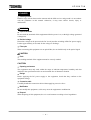
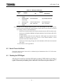
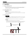
6 F 2 S 0 7 3 8 INSTRUCTION MANUAL GPS RECEIVER UNIT HHGP1 © TOSHIBA Corporation 2001 All Rights Reserved. ( Ver. 1.6 ) 6 F 2 S 0 7 3 8 Safety Precautions Before using this product, please read this chapter carefully. This chapter describes the safety precautions recommended when using the GPS receiver unit type HHGP1. Before installing and using the equipment, this chapter must be thoroughly read and understood. Explanation of symbols used Signal words such as DANGER, WARNING, and two kinds of CAUTION, will be followed by important safety information that must be carefully reviewed. DANGER Indicates an imminently hazardous situation which will result in death or serious injury if you do not follow the instructions. WARNING Indicates a potentially hazardous situation which could result in death or serious injury if you do not follow the instructions. CAUTION Indicates a potentially hazardous situation which if not avoided, may result in minor injury or moderate injury. CAUTION Indicates a potentially hazardous situation which if not avoided, may result in property damage. 1 6 F 2 S 0 7 3 8 DANGER • Installing arrester Install a surge arrester between the antenna and the GPS receiver and ground it in accordance with the guidelines in this manual. Otherwise, it may cause electric shocks, injury or malfunction. WARNING • Exposed terminals Do not touch the terminals of this equipment while the power is on, as the high voltage generated is dangerous. • Residual voltage Hazardous voltage can be present in the DC circuit just after switching off the DC power supply. It takes approximately 30 seconds for the voltage to discharge. • Fibre optic When connecting this equipment via an optical fibre, do not look directly at the optical signal. CAUTION • Earth The earthing terminal of the equipment must be securely earthed. CAUTION • Operating environment The equipment must only used within the range of ambient temperature, humidity and dust detailed in the specification and in an environment free of abnormal vibration. • Ratings Before applying the DC power supply to the equipment, check that they conform to the equipment ratings. • Connection cable Carefully handle the connection cable without applying excessive force. • Modification Do not modify this equipment, as this may cause the equipment to malfunction. • Disposal When disposing of this equipment, do so in a safe manner according to local regulations. 2 6 F 2 S 0 7 3 8 Contents Safety Precautions 1 1. Introduction 5 2. Characteristics 5 3. Configuration 6 3.1 3.2 6 7 4. 5. 6. 7. 8. Configuration of GPS Receiver Unit Outline of GPS Receiver Unit and Function Handling 8 4.1 4.2 4.3 8 9 9 Setting the GPS Receiver Unit How to Turn on the Power Checking the 1PPS Signal Operation 10 5.1 5.2 10 11 1PPS Signal Output Time Data Output Installation 12 6.1 6.2 6.3 6.4 6.5 6.6 12 12 12 15 15 16 Receipt of GPS Receiver Unit Installing GPS Receiver Unit Installing Antenna Installing Surge Arrester Installing Fibre Optics Connecting the Power Supply and the Earthing Terminal Preparation for Installation 17 7.1 7.2 7.3 17 17 18 Selecting an Antenna and Cables Selecting Coaxial Cables and Conversion Adapters Selecting an Antenna Installation Location Maintenance 19 8.1 8.2 19 19 Regular Maintenance Troubleshooting 3 6 F 2 S 0 7 3 8 Appendix A Outline of GPS Rceiver Unit 21 Appendix B Technical Data 23 Appendix C Specification of Recommended Antenna and Arrester 27 Appendix D Supplement 31 The data given in this manual are subject to change without notice. (Ver. 1.6) 4 6 F 2 S 0 7 3 8 1. Introduction The GPS (Global Positioning System) receiver unit is a device that receives the information from satellites and outputs time signals synchronous to UTC (Universal Coordinated Time) to external devices. The GPS receiver unit provides multiple outputs with optical signals for noise immunity. 2. Characteristics ■ Highly accurate time signal output Realizes a precision with respect to ±2µs for UTC (UTC: Universal Coordinated Time) (excluding the propagation delay time on the cable). ■ Reduced cabling work Adopting the signal superimposition method, the unit can be connected to an external device with a single optical fibre only. ■ Application to a large system Equipped with eight ports for output, the time distribution can be made to multiple devices separated from each other by a maximum of 1 km. ■ High reliability Aimed at reducing the number of parts through high-integration circuits and high-density mounting technology, thus securing high reliability. 5 6 F 2 S 0 7 3 8 3. Configuration 3.1 Configuration of GPS Receiver Unit Figure 3.1.1 shows the configuration of the GPS receiver unit. The GPS receiver unit receives electromagnetic signals from satellites through an antenna and outputs time data to external devices. Through an internal receiver, the unit generates serial time data and 1-second pulses (1PPS signals), based on the received electromagnetic signal. Each 1PPS signal occurs at the instant in time given by its accompanying frame of serial data. To reduce the number of cables to external devices, time data and 1PPS signals are superimposed through a mixing circuit before being output to the optical fibre. Antenna Backup Capacitor Receiver Time data 1 Pulse per second (1PPS) Mixing Circuit E/O E/O E/O E/O E/O E/O E/O E/O Electrical-to-optical Converter Fibre-optic Cable Power supply +48V Noise DC/DC Filter Converter 0V Figure 3.1.1 +5V 0V Configuration of GPS Receiver Unit 6 6 F 2 S 0 7 3 8 3.2 Outline of GPS Receiver Unit and Function Figure 3.2.1 shows outline and functions of GPS receiver unit. ④ FRONT VIEW ① ②③ ⑦ ⑥ ⑤ REAR VIEW 48V ⑧ No. Device Indication Functions ① Yellow LED 5V Turns on when the power (5Vdc) is supplied. ② Yellow LED 1PPS OUT Blinks when 1PPS signals are output synchronously with UTC. ③ Red LED ERROR Turns on when the internal crystal oscillator stops. ④ DIP switches DSW Set the GPS receiver unit settings. During operation, these DIP switches are covered to prevent erroneous operations. ⑤ Signal output ports OPT.OUT Outputs time signals. The optical fibre is connected here. ⑥ Power supply switch INPUT Turns on or off the power of the GPS receiver unit. ⑦ Terminal block __ The 48V dc power is applied and the earth cable is connected. P: 48Vdc, N: 0Vdc, E: earth ⑧ Antenna terminal ANT.IN The antenna cable is connected. Figure 3.2.1 Outline and Functions of GPS Receiver Unit 7 6 F 2 S 0 7 3 8 4. Handling 4.1 Setting the GPS Receiver Unit The GPS receiver unit is set in accordance with the requirements of the system by using the DIP switches located on the front panel of the unit. To prevent erroneous operations, the DIP switches are protected with a cover. As shown in Figure 4.1.1, when the cover is rotated after loosening the cover screw with a screwdriver, the switches are exposed thus making it possible to handle them. Switches are handled with a sharp-pointed object such as a screwdriver and set to “ON” or “OFF” by pushing them up or down respectively. After accessing the switches, tighten the cover screw to its original state. DSW 1234 Figure 4.1.1 Switch Operation Method Four switches are numbered 1 to 4 from left to right. (The numbers are indicated on their respective switches.) Table 4.1 shows the function and setting of each switch. (All the switches are set to “OFF” for default setting.) 8 6 F 2 S 0 7 3 8 Table 4.1 Setting the Switches Switch No. Setting Function ON OFF (default) 1 Location mode change Location fixing mode Location estimation mode 2 Reliability/TRAIM mode change Normal/TRAIM OFF High-reliability/TRAIM ON 3 Optical level test Continuous light emission Normal light emission 4 Clock range change 2020 – 2039 (Year) 2001 – 2019 (Year) Note: Settings can be changed when the power is ON, but changes are not valid until the power has been switched OFF and ON again, except in the case of switch 3 for optical level testing, which is valid immediately. - In the case of location mode, the location estimation mode (OFF) should be used. - In the case of reliability/TRAIM, the High-reliability/Train ON mode (SW-OFF) should be used. - In high-reliability mode, the unit outputs the 1PPS signal only when no failed satellites are detected. In the case of two or more failed satellites, correct operation of the unit cannot be assured. - In the case of clock range change, the switch should be OFF before 2019 and ON after 2020. For the details, see the Appendix D. 4.2 How to Turn on the Power Turn on the power switch. Power ON is confirmed by the illumination of the "5V" LED on the front panel of the unit. 4.3 Checking the 1PPS Signal After the power is turned on, check that 1PPS signals are output. If 1PPS signals are not output, it is impossible to use the time signals that are output from the GPS receiver unit. Output of 1PPS signals is confirmed by the blinking of the "1PPS OUT" LED on the front panel of the unit. 9 6 F 2 S 0 7 3 8 5. Operation 5.1 1PPS Signal Output The GPS receiver unit outputs 1PPS signals with each pulse defining the instant of time described by the preceding frame of serial data. (For the time signal transmission format, refer to Appendix D.) Following power-up, the GPS receiver begins outputting 1PPS signals after the acquisition of the almanac data and the estimation of the receiver location (or the antenna location to be more exact) are completed. Almanac data received from the satellites include satellites outline orbit information and UTC time correction parameters. It takes about 12 to 30 minutes to acquire the data. The almanac data is backed up temporarily following power-down. If power is removed for 16 hours or more, then the data back-up may be lost and will have to be re-acquired on power-up. If the almanac data back-up is valid on power-up, acquisition of almanac data is unnecessary. To estimate the location, signals from four or more satellites are required in the case of normal mode; and five or more are required in the case of high-reliability mode. Note: If the antenna is positioned in the shade of buildings, or in other locations where it is difficult to receive satellite signals, then location estimation may take a longer time or may even be impossible. If satellites are closely aligned in relation to the receiver, then it may not be possible to achieve a location estimate, even when the necessary numbers of signals are received. The reason for this is that, as the angle between received signals becomes small, the error in location estimation becomes large. Accordingly, installing an antenna in a location of narrow visual field such as between tall buildings may make the location estimation impossible. When using the high-reliability mode and/or TRAIM function, the alignment of satellites has even stricter limits. The location estimation may take more than an hour depending on constellation of satellites in case of the high-reliability mode. The location estimation is required each time the power is turned on. After the location estimation is completed, the 1PPS signal is output in normal mode if signals from one or more satellites are received; and two or more in high-reliability mode. The initialization time for the 1PPS signal at power-up varies as shown in Table 5.1.1, depending on the state of the almanac data back-up. Table 5.1.1 1PPS Output Start Time Back up of almanac data Initial time needed for 1PPS signal output from power on Lost 30 seconds to 1 hours (*1) Available 10 seconds to 1 hours (*1) (*1) It may take further time depending on constellation of satellites and antenna position. 10 6 F 2 S 0 7 3 8 Number of receivable satellite signals Five receivable satellite signals Four receivable satellite signals 6 5 Two receivable satellite signals 4 3 One receivable satellite signal 2 1 Time 0 1PPS output Stop Power ON (In the case of normal mode) Almanac data reception (12 to 30 minutes) Figure 5.1.1 5.2 1PPS output 1PPS output 1PPS stop 1PPS output (In the case of highreliability mode) Receiving Satellite Signals and 1PPS Output Status Time Data Output On power-up, time data (serial data consisting of year-month-date and hour:minute:second) is output from the receiver's internal RTC (real time clock). If satellite signals are received, then time data transmitted by the satellite (i.e., GPS time) is output until acquisition of the almanac data is completed. The GPS time deviates from UTC time by an accumulated number of leap seconds. When reception of the almanac data is completed, then UTC time is output. Any device receiving this output data can distinguish between the RTC, GPS and UTC time data, since this is indicated in the data itself. 11 6 F 2 S 0 7 3 8 6. Installation 6.1 Receipt of GPS Receiver Unit When GPS receiver units are received, carry out the acceptance inspection immediately. In particular, check for damage during transportation, and if any is found, contact the vendor. Always store the GPS receiver units in a clean, dry environment. 6.2 Installing GPS Receiver Unit CAUTION Do not remove flanges from the main unit, as this may cause a failure. The flanges attached to both sides of the unit are used to fix the main unit to a rack or plain table installed in a stable location. 6.3 Installing Antenna DANGER A surge arrester must be installed between the antenna and the GPS receiver unit. It must be grounded according to the methods specified in section 6.4 so as to prevent injury or malfunction. Install the antenna in the specified location in the method shown in the diagrams below. CAUTION An improper antenna installation location may cause malfunctions. Locate the antenna as far as possible from other antennas. If the antenna is located within one meter from other antennas, it may not be possible to receive the GPS signal correctly. Another antenna Antenna More than 1 meter Locate over the top of fence. Locate over the top of fence. 12 6 F 2 S 0 7 3 8 Don’t locate in shade of obstructing objects (Box, antenna, etc.). Don’t locate in shade of obstructing objects (Box, antenna, etc.) Next, connect the antenna to the arrestor with a coaxial cable. The following antennas are recommended: GPA-014B or GPA-017S manufactured by Furuno Electric Co., Ltd. The specifications for and dimensions of these antennas are described in Appendix C. The antenna should be fixed to a support pole with Debe clamps and U bolts. An example installation of the Furuno Electric antenna, using the accompanying clamps, is shown in Figures 6.3.1, 6.3.2 and 6.3.3. Antenna Wind the tape to cover the whole of junction and U-shaped gap. Auxiliary bracket Pipe Leave the connector slightly loose so that no excessive force is applied. Connector junction. mounting Support pole (φ25 to 70) Convex Insulation prevention measure (Autofusion tape, vinyl tape or water-proof cap) Figure 6.3.1 Parker clamp Antenna cable An Example of Installation, Using GPA-017S for Antenna 13 6 F 2 S 0 7 3 8 Debe clamp Antenna Connector junction Insulation treatment (Autofusion tape, vinyl tape or water-proof cap) Fix the cable to the support cable by making a circle while making sure the cable is long enough. Coaxial cable Support pole (φ38 to 64) Figure 6.3.2 An Example of Installation, Using GPA-014B for Antenna (A) Antenna Parker clamp Leave the connector slightly loose so that no excessive force is applied. Auxiliary bracket Connector junction. Support pole (φ27 to 90) Insulation prevention measure (Autofusion tape, vinyl tape or water-proof cap) Figure 6.3.3 mounting Tape Antenna cable An Example of Installation, Using GPA-014B for Antenna (B) 14 6 F 2 S 0 7 3 8 6.4 Installing Surge Arrester The GPS antenna must be installed outdoors, so a surge arrestor is required as a measure against induced surges due to lightening. (This is not effective against a direct lightening strike.) The arrestor should be installed at the point where the coaxial cable from the antenna enters the building. A recommended arrestor is CA-23RS made by Daiichi Denpa Kogyo. The specifications for and the appearance diagram of the arrestor are described in Appendix C. The surge arrestor is not water-proof and should be installed in a box. Connect the coaxial cable to the arrestor by an N-type connector. Stitch or solder a copper earth wire, 2.5 to 3.2 mm in diameter, to the earthing terminal on the arrestor. Connect the other end of the wire to the arrestor’s own earthing point. Make the connection distance between the arrester and the earthing point as short as possible and protect the earth cable with an insulation pipe. The surge arrestor must have its own direct connection to earth and must not share an earth connection with other equipment. Failure to comply with this requirement will result in risk of electric shock at time of lightening strike. 6.5 Installing Fibre Optics For the fibre optic connection, multi-mode GI fibre (62.5/125 µm) is used. When laying fibre optic lines, ensure a minimum curvature radius of 50 mm. CAUTION Do not bend the fibre optic cable sharply, as this may damage it and may cause malfunctions. Ensure that fibre optic connectors are fixed securely. 15 6 F 2 S 0 7 3 8 6.6 Connecting the Power Supply and the Earthing Terminal Connect the 48Vdc power cable and the earth cable to the terminal block with M4 crimped terminals. For safety purposes, make sure that the earth connection is reliable. CAUTION The earthing terminal must be securely earthed. The failure to ground may cause malfunctions, electric shocks or injury. Fibre optic cable to relay P N 48V E Adapter Earth Antenna Adapter Co-axial cable Arrester Co-axial cable Earth (Earth the arrester only.) Figure 6.6.1 External Connection of GPS Receiver Unit 16 6 F 2 S 0 7 3 8 7. Preparation for Installation The following issues should be considered prior to commencing installation of the system. 7.1 Selecting an Antenna and Cables The choice of antenna and cable types should be made based on the distance from the antenna installation site to the GPS receiver unit installation site, and also on the cabling conditions. Coaxial cables of characteristic impedance 50 ohms are required. The signal frequency is 1.57GHz. The antennas may be selected according to the distance between the sites. In the case of areas where snow is prevalent, the use of pole-shaped antennas is advisable. The maximum extension lengths of cables based on the combinations of antennas and cables are shown in Table 7.1.1. It shows the lengths from the antenna to the GPS receiver unit. Table 7.1.1 Maximum Extension Lengths of Cables Based on Combinations of Antennas and Cables Coaxial Cable Type 7.2 RG213 Fujikura 5D-FB Belden 9913 Westflex 103 Fujikura 8D-FB GPA-017S antenna 16m 25m 35m 35m 35m GPA-014B antenna 33m 50m 75m 75m 75m Selecting Coaxial Cables and Conversion Adapters N-type (NP) connectors are installed on both ends of the coaxial cables. Conversion adapters are required, since different types of connector are fitted on the antenna, surge arrestor and GPS receiver. Required conversion adapters are as shown in Table 7.2.1. Table 7.2.1 List of Conversion Adapters Part Required conversion adapter Remark Connector conversion from coaxial cable to antenna NJ-BNCP adapter or NJ-TNCP conversion cable (within 1 m) Connector conversion from the coaxial cable to the GPS receiver unit NJ-BNCP adapter The 5D-FB and RG213 cables can be fitted with a BNC-P connector, in which case, no conversion adapter is needed for connection to the BNC-fitted antenna and GPS receiver unit. 17 6 F 2 S 0 7 3 8 7.3 Selecting an Antenna Installation Location CAUTION If antenna is not located in the method described below, it may not be possible to receive the GPS signal correctly. Obstructing object allowed in this area. is not 15°(maximum) Antenna Support pole (fix to fence etc.) Roof of building Neighbouring building The antenna is installed outdoors to receive satellite transmissions. It should be installed in a location that offers an unobstructed view of the sky with an elevation angle of 15 degrees to horizontal. This is imperative for operation in high-reliability mode with operation of the TRAIM function, since it is necessary to received signals from satellites which are widely spaced. These restrictions can be relaxed for normal mode operation. Since the alignment of satellites varies during the course of a day, it is necessary to test that the installation is adequate to allow immediate location estimation and continuous 1PPS output for an entire one day period. On sites where installation conditions are not ideal then it may be necessary to conduct a survey to establish whether reception quality is adequate. This may include situations where the antenna must be mounted on a wall, or if the visual field is narrow or if the site is close to structures which reflect electromagnetic waves. 18 6 F 2 S 0 7 3 8 8. Maintenance 8.1 Regular Maintenance Surge arrestors are degraded by lightening induced voltages, resulting in changes to their discharge breakdown voltage. They require periodic checks and should be replaced if necessary. They can be checked by removing the internal components from the arrestor cabinet. The glass pipe part should be inspected and if it has turned black then replacement is required. CAUTION The surge arrestor must be periodically maintained to prevent malfunction. 8.2 Troubleshooting In the event of failure or unexpected behaviour of the unit, the following items should be checked. Symptom Possible cause and / or remedy "5V" LED is off. Check that power connections to the unit are made correctly and that the power supply switch on the front panel is ON. If so, then a failure of the internal power supply unit is a possible cause. "ERROR" LED is on. The GPS receiver unit is failed. The internal circuit clock has stopped oscillating. "1PPS OUT" LED does not start to blink after power ON. Check the antenna location and connection. Check that the DIP switches are set to proper positions. It takes a long time until "1PPS OUT" LED starts blinking after power ON. In cases where the power has been turned off for 16 hours or more, internal back-up data may be lost and it may take about 30 minutes before the unit is ready to output the 1PPS signal. This case is not an error. However, if 1PPS is not output after about 30 minutes, check that the antenna is installed in a satisfactory location. During operation, the 1PPS output is interrupted. Check to make sure that the antenna is installed in a satisfactory location. Data cannot be detected on the receiving device. Check that the optical fibre is connected securely and that it is not damaged or severely bent (minimum bend radius is 50mm). The 1PPS signal or the time data is irregular. Possible failure of the internal receiver. "1PPS OUT" LED does not turn on. Check that the DIP switches are set to proper positions. If a failure continues, stop using the GPS receiver unit and contact the vendor. 19 6 F 2 S 0 7 3 8 20 6 F 2 S 0 7 3 8 Appendix A Outline of GPS Receiver Unit 21 6 F 2 S 0 7 3 8 Outline 140.0 2.3 260.0 12.5 7.0 70.0 45.0 12.5 4-R3.5 7.0 290.0 308.0 Panel cutout 4-φ7 hole 45 45 15 15 266 22 72 162.5 6 F 2 S 0 7 3 8 Appendix B Technical Data 23 6 F 2 S 0 7 3 8 TECHNICAL DATA Ratings DC power supply: 48Vdc-10W (Operative range: 38.4 to 57.6Vdc) AC ripple on dc supply IEC 60255-11: maximum 12% DC supply interruption IEC 60255-11: less than 10ms at 48Vdc Permitted duration of dc supply voltage interruption to maintain normal operation Mechanical design Weight: 2.7kg Installation: Flush mounting Receiving function Number of receiving satellites: Eight satellites received in parallel Receive signals: L1 C/A code Receive frequency: 1575.42 MHz Time transfer accuracy Within±2µs with respect to UTC(When the receiver is tracking GPS Satellites) Data backup Data life: more than 16 hours Communication Interface Connection: ST connector Cable type: GI multimode optical fibre (62.5/125µm or 50/125µm) Wavelength: 820nm Cable Length: 0 to 1km (3dB/km) GPS antenna interface Preamp power supply for Antenna Min 4.5V(at 20mA), Min 4.0V(at 40mA) Connection: BNC connector Cable type: 50 ohm coaxial cable GPS antenna NF: Max 3dB Gain: 10 to 35dB(Antenna + Amp + Cable) 24 6 F 2 S 0 7 3 8 Environmental Performance Claims for GPS Receiver Test Standards Details Atmospheric Environment Temperature IEC60068-2-1/2 Operating range: -10°C to +55°C. Storage / Transit: -25°C to +70°C. Humidity IEC60068-2-3 56 days at 40°C and 93% relative humidity. Mechanical Environment Vibration IEC60255-21-1 Response - Class 1 Endurance - Class 1 Shock and Bump IEC60255-21-2 Shock Response Class 1 Shock Withstand Class 1 Bump Class 1 Seismic IEC60255-21-3 Class 1 High Voltage Environment Dielectric Withstand IEC60255-5 2kVrms for 1 minute between PSU terminals and earth. High Voltage Impulse IEC60255-5 Three positive and three negative impulses of 5kV(peak), 1.2/50µs, 0.5J between all terminals and between PSU terminals and earth. Electromagnetic Environment High Frequency Disturbance / IEC60255-22-1 Class 3 1MHz 2.5kV applied to PSU terminals in common mode. 1MHz 1.0kV applied to PSU terminals in differential mode. Damped Oscillatory Wave IEC61000-4-12, EN61000-4-12 Class 3 0.1MHz 2.5kV applied to PSU terminals in common mode. 0.1MHz 1.0kV applied to PSU terminals in differential mode. Electrostatic Discharge IEC60255-22-2 Class 4 8kV contact discharge. 15kV air discharge. Radiated RF Electromagnetic Disturbance IEC60255-22-3 Class 3 Field strength 10V/m for frequency sweeps of 80MHz to 1GHz and 1.7GHz to 2.2GHz. Additional spot tests at 80, 160, 450, 900 and 1890MHz. Fast Transient Disturbance IEC60255-22-4 Class 4 4kV, 2.5kHz, 5/50ns applied to PSU terminals in common mode. Conducted RF Electromagnetic Disturbance IEC60255-22-6 Class 3 10Vrms applied over frequency range 150kHz to 100MHz. Additional spot tests at 27 and 68MHz. Conducted Disturbance over Freq. Range 15Hz to 150kHz IEC61000-4-16, EN61000-4-16, Class 3 Varying voltages applied in common mode as follows: 15Hz to 150Hz: 10V → 1Vrms (20dB/decade) 150Hz to 1.5kHz: 1Vrms 1.5kHz to 15kHz: 1 → 10Vrms (20dB/decade) 15kHz to 150kHz: 10Vrms Power Frequency Disturbance IEC60255-22-7 300V 50Hz for 10s applied to PSU terminals in common mode. 25 6 F 2 S 0 7 3 8 Surge Immunity IEC61000-4-5, EN61000-4-5 1.2/50µs surge applied to PSU terminals in common/differential modes: 2kV/1kV (peak) Conducted and Radiated Emissions EN55022 Class A Conducted emissions: 0.15 to 0.50MHz: <79dB (peak) or <66dB (mean) 0.50 to 30MHz: <73dB (peak) or <60dB (mean) Radiated emissions: 30 to 230MHz: <30dB 230 to 1000MHz: <37dB Power Frequency Magnetic Field IEC61000-4-8, EN61000-4-8, Class 4 Field applied at 50Hz with strengths of: 30A/m continuously, 300A/m for 1 second. Pulsed Magnetic Field IEC61000-4-9, EN61000-4-9, Class 5 6.4/16µs magnetic pulses (positive and negative) applied with magnitude 1000A/m. Damped Oscillatory Magnetic Field IEC61000-4-10, EN61000-4-10, Class 5 Oscillation frequencies of 0.1MHz and 1MHz applied with magnitude 100A/m. European Commission Directives 89/336/EEC Compliance with the European Commission Electromagnetic Compatibility Directive is demonstrated according to generic EMC standards EN50081-2 and EN50082-2. 73/23/EEC Compliance with the European Commission Low Voltage Directive is demonstrated according to generic safety standards EN61010-1 and EN60950. 26 6 F 2 S 0 7 3 8 Appendix C Specification of Recommended Antenna and Arrester 27 6 F 2 S 0 7 3 8 Recommended Antenna Type GPA-014B GPA-017S FURUNO Electric Co.,Ltd. FURUNO Electric Co.,Ltd. Operating connector BNC-J TNC-J Applicable connector BNC-P TNC-P 29 to 35dB 22 to 33dB No more than 2.1dB No more than 1.6dB 4 to 13V 4.0 to 5.5V 25 to 30mA No more than 25mA Operating temperature - 30 to + 80℃ - 25 to + 65℃ Storage temperature - 40 to + 85℃ - 35 to + 75℃ Weight Approx. 300g Approx. 123 ± 30g Manufacturer Gain Preamplifier noise index Supply voltage Current consumption φ42.2 φ69 24 290 85.5 52 3D-XV 3D-2V 200 200 BNC-J TNC-J GPA-017S GPA-014B Outline of Antenna 28 6 F 2 S 0 7 3 8 Recommended Arrester Type CA-23RS Manufacturer DAI-ICHI DENPA KOGYO CO., LTD. Frequency range DC – 2500MHz VSWR No more than 1.1 Loss No more than 0.2dB Withstand power 200W PEP Discharge breakdown voltage DC 230V ±15% Impulse wave discharge voltage 1,000V Impulse wave current endurance 6,000A Impulse wave repetitive discharge endurance (1×40) µs, 500A, at least 500 times Insulation resistance at 100Vdc At least 10,000MΩ Connector N-J / N-J Dimensions 78(W)×48(H)×20(D)mm Weight 113g N-J CONNECTOR 48 30 EARTH CABLE φ2.5 – φ3.2 19 19 78 CA-23RS Outline of Arrester 29 20 6 F 2 S 0 7 3 8 30 6 F 2 S 0 7 3 8 Appendix D Supplement 31 6 F 2 S 0 7 3 8 1. Time Signal Transmission Format The time signal format is shown below, consisting of 4,800bps serial data indicating the time, and 1PPS timing signal indicating the instant of time corresponding to the serial data. 1PPS timing signal Serial data 4800bps Signal for next second Signal code format: ASCII codes based on NMEA-0183 data Output data: GPtps data (time and 1PPS flag) GPtst data (self-test result) 2. Date Rollover The GPS week number sent from the satellite returns to 0 (i.e., rollover) every 19.6 years; therefore, the GPS receiver unit cannot output the date data correctly. This is the rollover problem. To solve this problem, the GPS receiver unit provides a DIP switch. - When the DIP switch 4 is set to OFF and the power is ON, the GPS receiver unit starts outputting the date and time from any date between April in 2001 and September in 2020. - When the DIP switch 4 is set to ON and the power is ON, the GPS receiver unit starts outputting the date and time from any date between October in 2019 and March in 2039. The default setting of the DIP switch 4 is OFF. After 2020, the DIP switch 4 should be set ON so that the GPS unit outputs the date data correctly. Note 1: The date and time data from the GPS receiver unit are used for the recording data of GRL100 relay and do not influence the function of GRL100 relay. The 1 PPS signal is output independently of the switch 4 setting. Note 2: For one year from October, 2019 to September, 2020, any setting of the DIP switch 4 is allowed. So, in this term, the changing of the DIP switch 4 is recommended. 3 High-reliability Mode and TRAIM Function TRAIM (Time Receiver Autonomous Integrity Monitoring) is a function which allows the unit to detect an error in the signal from a satellite. For operation of this function, it is necessary to receive one additional signal to the minimum number normally required for output of the 1PPS 32 6 F 2 S 0 7 3 8 pulse. If the necessary number of satellites are available then the unit carries out error detection and removal of erroneous signals. In the event of two or more satellites in error, the operation is not assured. In high-reliability mode, the receiver will only output the 1PPS signal when no TRAIM alarm occurs. If any satellite is in error then it must be excluded, and so two or more satellites are required for the purpose of outputting 1PPS. Satellite alignment is subject to strict limits for operation of the TRAIM function. The antenna must be located with a wide field of view. 4. Conditions for Receiving Electric Waves from Satellites Signals from satellites at an elevation angle of less than 5 degrees are too weak to be received. In terms of the impact of weather, satellite signals can be received correctly while it is raining or lightly snowing, or while a small amount of snow is piled on the antenna; however, during lightening or heavy snow, the receive status may deteriorate temporarily. 33 6 F 2 S 0 7 3 8 Version-up Records Version No. Date Revised Section Contents 0.0 May. 23, 2001 -- First issue. 1.0 Jun. 22, 2001 3.2 5.1 6.6 7.1 Appendices Modified Figure 3.2.1. Modified Figure 5.1.1 Modified Figure 6.6.1. Modified descriptions in Section 7.1. Modified Appendices B, C, I and K. 1.1 Jul. 19, 2001 -4.1 Appendix D Corrected Type of GPS unit. (HHGP3 →HHGP1) Modified descriptions in Section 4.1. Modified descriptions 0f “2. Date rollover” in Appendix D. 1.2 Jul. 25, 2001 6.3 Corrected Type of GPS antenna. (GPA-01T→GPA-016, GPA-14B→GPA-016B) 1.3 Sep. 10, 2001 3.1 3.2 4 5.1 6.6 8.2 Appendices Modified Figure 3.1.1. Modified Figure 3.2.1. Modified descriptions in Chapter 4 and Section 4.1. Modified descriptions in Section 5.1. Modified Figure 6.6.1. Modified descriptions in Section 8.2. Modified Appendices A, B, C and D. 1.4 Jul. 30, 2002 Appendix B Modified the description in Conducted and Radiated Emissions. 1.5 Mar. 28, 2003 6.3 7.1 Appendix C 1.6 May.30, 2003 4.1 6.3 7.3 Changed Type of GPS antenna and Figure 6.3.1. (GPA-016→GPA-017S) Added Figure 6.3.3. Modified Table 7.1.1. Changed specification and outline of antenna. (GPA-016→GPA-017S) Added the description in Note of Table 4.1. Added the description in Caution. Added Caution. 34