1
i
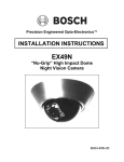
EVR - DVR
Digital Video Recorder
User Manual
DVR8-X
EVR8-X
DVR16-X
EVR16-X
EVR32-X
EVR64-X
model no.
Please carefully read these instructions before using this product.
Save this manual for future use.
1
ii
Surveillix™ KV-EVR / KV-DVR
Operations Manual
iii
iv
Surveillix™ DVR
User Guide
Manual Edition 26158AM – SEPTEMBER 2006
Printed in USA
No part of this documentation may be reproduced in any means, electronic or mechanical, for any purpose, except as expressed in
the Software License Agreement. Toshiba shall not be liable for technical or editorial errors or omissions contained herein. The
information in this document is subject to change without notice.
THE INFORMATION IN THIS PUBLICATION IS PROVIDED “AS IS” WITHOUT WARRANTY OF ANY KIND. THE ENTIRE RISK
ARISING OUT OF THE USE OF THIS INFORMATION REMAINS WITH RECIPIENT. IN NO EVENT SHALL TOSHIBA BE LIABLE
FOR ANY DIRECT, CONSEQUENTIAL, INCIDENTAL, SPECIAL, PUNITIVE, OR OTHER DAMAGES WHATSOEVER
(INCLUDING WITHOUT LIMITATION, DAMAGES FOR LOSS OF BUSINESS PROFITS, BUSINESS INTERRUPTION OR LOSS
OF BUSINESS INFORMATION), EVEN IF TOSHIBA HAS BEEN ADVISED OF THE POSSIBILITY OF SUCH DAMAGES AND
WHETHER IN AN ACTION OR CONTRACT OR TORT, INCLUDING NEGLIGENCE.
This software and documentation are copyrighted. All other rights, including ownership of the software, are reserved to DVR Support
Center. TOSHIBA, and Surveillix are registered trademarks of TOSHIBA CORPORATION in the United States and elsewhere;
Windows, and Windows 2000 are registered trademarks of Microsoft Corporation. All other brand and product names are
trademarks or registered trademarks of the respective owners.
The following words and symbols mark special messages throughout this guide:
WARNING: Text set off in this manner indicates that failure to
follow directions could result in bodily harm or loss of life.
CAUTION: Text set off in this manner indicates that failure to
follow directions could result in damage to equipment or loss of
information.
v
LIMITED WARRANTY
DIGITAL VIDEO RECORDER
Promptly register your product with Toshiba on-line at http://www.toshiba.com/taisisd. By registering your product you will be
eligible for periodic updates, announcements, and special offers applicable for your product. You will have access to extended
warranty options, upgrades (as applicable), useful tips, on-line troubleshooting, and the ability to schedule service on-line if
necessary. The Imaging Systems Division of Toshiba America Information Systems, Inc. ("ISD") makes the following limited
warranties. These limited warranties extend to the Original End-User ("Your[r]").
Limited Two (2) Year Warranty of Labor and Parts
ISD warrants this product and parts against defects in material or workmanship for a period of two years from the date of original
retail purchase by the end-user. During this period, ISD will repair or replace a defective product or part with a new or refurbished
item. The user must deliver the entire product to an ISD authorized service center. The user is responsible for all transportation
and insurance charges for the product to the Service Center. ISD reserves the right to substitute Factory Refurbished Parts and /
or Factory Refurbished Product in place of those in need of repair.
Step-by-step Procedures - How to Obtain Warranty Service
[1] Verify operation of the unit by checking the instruction manual and web site for the latest updates at
www.toshiba.com/taisisd
[2] If there is a defect in material or workmanship, schedule service on-line or contact the Digital Support Center for an individual
Tracking Number and the location of the nearest ISD authorized service center. To contact technical support call (866) ASK-4-DVR
[866-275-4387].
[3] Arrange for delivery of the product to the ISD authorized service center. Products must be insured and securely packed,
preferably in the original shipping carton. A letter explaining the defect and a copy of the bill of sale or other proof of purchase must
be enclosed with a complete return street address and daytime telephone number. The Tracking Number should also be indicated
on your documents. Charges for transportation and insurance must be prepaid by the end-user.
Your Responsibility, warranties are subject to the following conditions:
[1] You must retain the bill of sale or provide other proof of purchase.
[2] You must schedule service within thirty days after you discover a defective product or part.
[3] All warranty servicing of this product must be made by an ISD authorized service center.
[4] The warranty extends to defects in material or workmanship as limited above, and not to any products or parts that have been
lost or discarded by user. The warranty does not cover damage caused by misuse, accident, improper installation, improper
maintenance, or use in violation of instructions furnished by ISD. The warranty does not extend to units which have been altered or
modified without authorization of ISD, or to damage to products or parts thereof which have had the serial number removed, altered
defaced or rendered illegible.
ALL WARRANTIES IMPLIED BY STATE LAW, INCLUDING THE IMPLIED WARRANTIES OF MERCHANTABILITY AND
FITNESS FOR A PARTICULAR PURPOSE, ARE EXPRESSLY LIMITED TO THE DURATION OF THE LIMITED WARRANTIES
SET FORTH ABOVE. Some states do not allow limitations on how long an implied warranty lasts, so the above limitation
may not apply. WITH THE EXCEPTION OF ANY WARRANTIES IMPLIED BY STATE LAW AS HEREBY LIMITED, THE
FOREGOING EXPRESS WARRANTY IS EXCLUSIVE AND IN LIEU OF ALL OTHER WITH RESPECT TO THE REPAIR OR
REPLACEMENT OF ANY PRODUCTS OR PARTS. IN NO EVENT SHALL ISD BE LIABLE FOR CONSEQUENTIAL OR
INCIDENTAL DAMAGES. Some states do not allow the exclusion or limitation of incidental or consequential damages so
the above limitation may not apply.
No person, agent, distributor, dealer, service station or company is authorized to change, modify or extend the terms of
these warranties in any manner whatsoever. The time within which an action must be commenced to enforce any
obligation of ISD arising under this warranty or under any statute, or law of the United States or any state thereof, is
hereby limited to one year from the date you discover or should have discovered, the defect. This limitation does not apply
to implied warranties arising under state law. Some states do not permit limitation of the time within which you may bring
an action beyond the limits provided by state law so the above provision may not apply to user. This warranty gives the
user specific legal rights, and user may also have other rights, which may vary from state to state.
TOSHIBA AMERICA INFORMATION SYSTEMS, INC.
Imaging Systems Division
Copyright © 2002 Toshiba America Information Systems, Inc. All rights reserved.
vi
Rack Mount Instructions
A) Elevated Operating Ambient – If installed in a closed or multi-unit rack assembly, the operating
ambient temperature of the rack environment may be greater than room ambient. Therefore,
consideration should be given to installing the equipment in an environment compatible with the
maximum ambient temperature (Tma) specified by the manufacturer.
B) Reduced Air Flow – Installation of the equipment in a rack should be such that the amount of air flow
required for safe operation of the equipment is not compromised.
C) Mechanical Loading – Mounting of the equipment in the rack should be such that a hazardous
condition is not achieved due to uneven mechanical loading.
D) Circuit Overloading – Consideration should be given to the connection of the equipment to the supply
circuit and the effect that overloading of the circuits might have on over current protection and supply
wiring. Appropriate consideration of equipment nameplate ratings should be used when addressing
this concern.
E) Reliable Earthing – Reliable earthing of rack-mounted equipment should be maintained. Particular
attention should be given to supply connections other than direct connections to the branch circuit
(e.g. use of power strips).
UL Notice
Underwriters Laboratories Inc. has not tested the performance or reliability of the security or signaling
aspects of this product. UL has only tested for fire, shock and casualty hazards as outlined in UL’s
Standard for Safety UL 60950-1. UL Certification does not cover the performance or reliability of the
security or signaling aspects if this product. UL MAKES NO REPRESENTATIONS, WARRANTIES OR
CERTIFICATIONS WHATSOEVER REGARDING THE PERFORMANCE OR RELIABILITY OF ANY
SECURITY OR SIGNALING RELATED FUNCTIONS OF THIS PRODUCT.
vii
CE Notice
This product is in conformity with the following European Directives:
ELECTROMAGNETIC COMPATIBILITY DIRECTIVE, 89/336/EEC
(as amended by 92/31/EECand by Article 5 of 93/68/EEC)
per the provisions of:
EN 55022:1994
EN 61000-3-2:1995
EN 61000-3-3:1995
CISPR 22:1997
EN 55024:1998
CISPR 24:1997
EN 61000-4-2:1995
EN 61000-4-3:2002
EN 61000-4-4:1995
EN 61000-4-5:1995
EN 61000-4-6:1995
EN 61000-4-11:1994
LOW VOLTAGE DIRECTIVE, 73/23/EEC
(as amended by Article 13 of 93/68/EEC)
per the provisions of:
EN 60950-1: 2001
Safety Precautions
WARNING
RISK OF ELECTRICAL SHOCK
DO NOT OPEN
WARNING :
TO REDUCE THE RISK OF ELECTRICAL
SHOCK, DO NOT REMOVE COVER. NO USER
SERVICEABLE PARTS INSIDE. REFER SERVICING TO
QUALI FIED
S ERVICE
P ERSO NNEL.
WARNING:
TO REDUCE THE RISK OF ELECTRICAL SHOCK, DO NOT EXPOSE THIS
APPLIANCE TO RAIN OR MOISTURE. DANGEROUS HIGH VOLTAGES ARE
PRESENT INSIDE THE ENCLOSURE. DO NOT OPEN THE CABINET. REFER
SERVICING TO QUALIFIED PERSONNEL ONLY.
viii
IMPORTANT SAFETY INSTRUCTIONS
1. Read Owner’s Manual
After unpacking this product, read the owner’s manual carefully, and follow all the operating and
other instructions.
2. Power Sources
This product should be operated only from the type of power source indicated on the label. If you
are not sure of the type of power supply to your business or home, consult your product dealer or
local power company.
3. Ventilation
Slots and openings in the cabinet are provided for ventilation and to ensure reliable operation of
the product and to protect it from overheating, and these openings must not be blocked or
covered. The product should not be placed in a built-in installation such as a bookcase or rack
unless proper ventilation is provided or the manufacturer’s instructions have been adhered to.
4. Heat
The product should be situated away from heat sources such as radiators. Heat registers, stoves,
or other products that produce heat.
5. Water and Moisture
Do not use this product near water. Do not exceed the humidity specifications for the product as
detailed in the Appendix section in this manual.
6. Cleaning
Unplug this product from the wall outlet before cleaning. Do not use liquid cleaners or aerosol
cleaners. Use a damp cloth for cleaning.
7. Power Cord Protection
Power-supply cords should be routed so that they are not likely to be walked on or pinched by
items placed against them, paying particular attention to cords at plugs, convenience receptacles,
and the point where they exit from the product.
8. Overloading
Do not overload wall outlets, extension cords, or integral convenience receptacles as this can
result in a risk of fire or electrical shock.
9. Lightning
For added protection for this product during storm, or when it is left unattended and unused for
long periods of time, unplug it from the wall outlet. This will prevent damage to the product due to
lightning and power line surges.
10. Object and Liquid Entry Points
Never insert foreign objects into the DVR unit, other than the media types approved by Toshiba,
as they may touch dangerous voltage points or short-out parts that could result in a fire or
electrical shock. Never spill liquid of any kind on the product.
11. Accessories
Do not place this product on an unstable cart, stand, tripod, bracket, or table. The product may
fall, causing serious personal injury and serious damage to the product.
ix
IMPORTANT SAFETY INSTRUCTIONS
12. Disc Tray
Keep your fingers well clear of the disc tray as it is closing. Neglecting to do so may cause
serious personal injury.
13. Burden
Do not place a heavy object on or step on the product. The object may fall, causing serious
personal injury and serious damage to the product.
14. Disc
Do not use a cracked, deformed, or repaired disc. These discs are easily broken and may cause
serious personal injury and product malfunction.
15. Damage Requiring Service
Unplug this product from the wall outlet and refer servicing to qualified service personnel under
the following conditions.
•
•
•
•
•
•
When the power–supply cord or plug is damaged.
If liquid has been spilled, or objects have fallen into the product.
If the product has been exposed to rain or water.
If the product does not operate normally by following the operating instructions. Adjust
only those controls that are covered by the operating instructions as an improper
adjustment of other controls may result in damage and will often require extensive work
by a qualified technician to restore the product to its normal operation.
If the product has been dropped or damaged in any way.
When the product exhibits a distinct change in performance – this indicates a need for
service.
16. Servicing
Do not attempt to service this product yourself as opening or removing covers may expose you to
dangerous voltage or other hazards. Refer all servicing to qualified personnel.
17. Replacement Parts
When replacement parts are required, be sure the service technician has used replacement parts
specified by the manufacturer or have the same characteristics as the original part. Unauthorized
substitutions may result in fire, electrical shock, or other hazards.
18. Safety Check
Upon completion of any service or repairs to this product, ask the service technician to perform
safety checks to determine that the product is in proper operating condition.
x
Notes on Handling
When shipping the DVR unit, the original shipping
carton packing materials come in handy. For maximum
protection, repack the unit as it was originally packed at
the factory.
Do not use volatile liquids, such as insect spray, near
the DVR unit. Do not leave rubber or plastic products in
contact with the DVR unit for long periods of time. They
will leave marks on the finish.
The top and rear panels of the DVR unit may become
warm after long periods of use. This is not a
malfunction.
Notes on Locating
Place the DVR unit on a level surface. Do not use it on
a shaky or unstable surface such as a wobbling table or
inclined stand.
When you place this DVR unit next to a TV, radio, or
VCR, the playback picture may become poor and the
sound may be distorted. In this case, place the DVR
unit away from the TV, radio, or VCR.
Notes on Cleaning
Use a soft dry cloth for cleaning.
For stubborn dirt, soak the cloth in a weak detergent
solution, wring well and wipe. Use a dry cloth to wipe it
dry.
Do not use any type of solvent, such as thinner and
benzene, as they may damage the surface of the DVR
unit.
If you use a chemical saturated cloth to clean the unit,
follow that product’s instructions.
Notes on Maintenance
This DVR unit is designed to last for long periods of time. To
keep your DVR unit always operational we recommend
regular inspection maintenance (cleaning parts or
replacement). For details contact your nearest dealer.
Note on Moisture Condensation
Moisture condensation damages the DVR unit. Please
read the following carefully.
Moisture condensation occurs during the following cases.
When you bring the DVR unit directly from a cold place
to a warm place.
When you use the DVR unit in a room where you just
turned on the heater, or a place where the cold wind
from the air conditioner directly hits the unit.
In the summer, when you use the DVR unit in a hot and
humid place just after you move the unit from an air
conditioned room.
When you use the DVR unit in a humid place.
Do not use the DVR unit when moisture condensation
may occur.
If you use the DVR unit in such a situation, it may damage
discs and internal parts. Remove any CD discs, connect the
power cord of the DVR unit to the wall outlet, turn on the
DVR unit, and leave it for two to three hours. After two to
three hours, the DVR unit will have warmed up and
evaporated any moisture. Keep the DVR unit connected to
the wall and moisture will seldom occur.
x
Table of Contents
PREFACE............................................................................................................. XIV
ABOUT THIS GUIDE ................................................................................................................................................ XIV
TECHNICIAN NOTES ............................................................................................................................................... XIV
INTRODUCTION .......................................................................................................... 1
WHAT IS A SURVEILLIX® DVR™............................................................................................................................1
NEW FEATURES ........................................................................................................................................................2
DVR DESCRIPTION ............................................................................................ 4
1.1
1.2
BASIC FEATURES .......................................................................................................................................5
FRONT PANEL CONTROLS AND LEDS ......................................................................................................6
1.2.1
1.2.2
KV-DVR .....................................................................................................................................................6
KV-EVR .....................................................................................................................................................7
1.3
REAR PANEL CONNECTORS ......................................................................................................................8
1.3.1
1.3.2
KV-DVR .....................................................................................................................................................8
KV-EVR .....................................................................................................................................................9
GETTING STARTED............................................................................................11
2.1
2.2
2.3
2.4
2.5
2.6
2.7
2.8
2.9
2.10
2.11
2.12
IDENTIFYING INCLUDED COMPONENTS ....................................................................................................12
KEYBOARD SETUP ...................................................................................................................................13
MOUSE SETUP .........................................................................................................................................13
MONITOR SETUP ......................................................................................................................................14
POWER SETUP .........................................................................................................................................14
CONNECTING A VIDEO SOURCE TO THE DVR.........................................................................................14
LOOPING OUTPUT TERMINATION.............................................................................................................14
CONNECTING SENSORS TO THE DVR .....................................................................................................15
CONNECTING CONTROL OUTPUTS TO THE DVR ....................................................................................15
LOOPING OUTPUTS ..................................................................................................................................16
ADDITIONAL OUTPUTS AND CONNECTORS .............................................................................................16
SWAPPABLE HARD DRIVES......................................................................................................................17
2.12.1 Swapping a Hard Drive .......................................................................................................................17
2.13
2.14
MONITOR SETUP ......................................................................................................................................18
OPTIONAL COMPONENTS ........................................................................................................................19
DVR BASICS .................................................................................................... 20
3.1
3.2
3.3
3.4
3.5
3.6
TURNING ON THE DVR.............................................................................................................................21
TURNING OFF THE DVR ...........................................................................................................................21
HVR/NVR REGISTRATION AND UPGRADE .............................................................................................22
NATIVE POS REGISTRATION AND UPGRADE ..........................................................................................24
DISPLAY SCREEN .....................................................................................................................................27
CAMERA VIEW ..........................................................................................................................................28
xi
3.7
3.8
RECORDING STATUS INDICATOR .............................................................................................................29
SCREEN DIVISION MENU ..........................................................................................................................29
SETUP OPTIONS............................................................................................... 31
4.1
SETUP OVERVIEW ....................................................................................................................................32
4.1.1
Setup Screen Overview ......................................................................................................................32
4.2
CAMERA SETUP .......................................................................................................................................33
4.2.1
Network Device Setup ........................................................................................................................34
4.3
MOTION ....................................................................................................................................................35
4.3.1
4.3.2
Creating a Motion Area.......................................................................................................................36
Activating an Alarm Output on a Motion Event............................................................................36
4.4
4.4.1
4.5
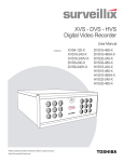
FRAME SETUP ..........................................................................................................................................37
MAXIMUM PPS TABLE (FRAME SETUP) .................................................................................................38
SCHEDULE SETUP (RECORDING) ............................................................................................................40
4.5.1
4.5.2
4.5.3
4.5.4
4.5.5
4.5.6
4.5.7
Schedule Setup (Sensor) ...................................................................................................................41
Creating a Recording Schedule (Motion and Continuous) .......................................................42
Creating a Recording Schedule (Sensor) ......................................................................................42
Scheduling Alarm Events ..................................................................................................................42
Scheduling Alarm Events to send video to the Emergency Agent .........................................43
Special Day Schedule .........................................................................................................................43
Creating and Editing a ‘Special Day’ Schedule............................................................................44
4.6
4.7
SENSOR ....................................................................................................................................................44
GENERAL..................................................................................................................................................45
4.7.1
4.7.2
4.7.3
4.7.4
4.7.5
4.7.6
4.7.7
4.7.8
Voice Warning.......................................................................................................................................46
Video Loss Alarm.................................................................................................................................46
Intensive Recording Overview..........................................................................................................47
Intensive Recording ............................................................................................................................47
Audio .......................................................................................................................................................48
Video Loss Alarm.................................................................................................................................48
Auto Sequencing..................................................................................................................................48
Network (Setup for Remote Connections).....................................................................................50
4.8
4.9
4.10
4.11
TWO-WAY AUDIO.....................................................................................................................................51
PTZ SETUP ..............................................................................................................................................53
INFORMATION ...........................................................................................................................................54
ADMINISTRATIVE ......................................................................................................................................55
4.11.1
4.11.2
4.11.3
4.11.4
User Management ................................................................................................................................56
User Rank...............................................................................................................................................56
Changing the Administrator Password..........................................................................................57
Storage Check ......................................................................................................................................57
4.12
4.13
INSTANT RECORDING ...............................................................................................................................58
ADJUSTING THE TIME AND DATE .............................................................................................................58
SEARCH OPTIONS........................................................................................... 60
5.1
5.2
SEARCH OVERVIEW .................................................................................................................................61
PLAY CONTROLS .....................................................................................................................................62
xii
5.3
5.4
5.5
5.6
5.7
5.8
HOUR / MINUTE CONTROL BAR...............................................................................................................62
ADVANCED OPTIONS ...............................................................................................................................63
SEARCH OPTIONS OVERVIEW .................................................................................................................64
PERFORMING A BASIC SEARCH ..............................................................................................................65
DAYLIGHT SAVINGS TIME ........................................................................................................................65
PRINT/OPEN/EXPORT IMAGES.................................................................................................................65
5.8.1
5.8.2
5.8.3
Print .........................................................................................................................................................66
Save to JPG or AVI ..............................................................................................................................66
Single Clip Backup ..............................................................................................................................67
5.9
5.10
5.11
5.12
5.13
INDEX SEARCH .........................................................................................................................................68
PREVIEW SEARCH ....................................................................................................................................70
OBJECT SEARCH .....................................................................................................................................71
GRAPHIC SEARCH....................................................................................................................................73
AUDIO PLAYBACK ....................................................................................................................................74
PAN / TILT / ZOOM .......................................................................................... 75
6.1
6.2
PAN/TILT/ZOOM OVERVIEW ................................................................................................................76
SETTING UP A PTZ CAMERA (DVR8-60 & DVR16-120 SEE BELOW) .................................................76
6.2.1
6.2.2
Supported Protocols ...........................................................................................................................77
Setting up a PTZ (DVR8-60 and DVR16-120 Models) ..................................................................78
6.3
6.4
6.5
6.6
6.7
PTZ SETUP ..............................................................................................................................................80
CREATING AND VIEWING PRESET POSITIONS .........................................................................................81
PTZ ADDRESS SETTING ..........................................................................................................................82
ACCESSING PTZ MENU’S ........................................................................................................................82
USING THE ONSCREEN COMPASS ...........................................................................................................83
6.7.1
Using the onscreen controller and Compass...............................................................................83
6.8
6.9
UNDERSTANDING TOURS .........................................................................................................................84
PTZ TOUR SCHEDULING .........................................................................................................................85
BACKING UP TO A CD-RW DRIVE ................................................................... 87
7.1
7.2
7.3
7.4
7.5
7.6
7.7
7.8
7.9
7.10
7.11
7.12
7.13
BACKUP OVERVIEW .................................................................................................................................88
DIRECTCD® FORMAT UTILITY ...............................................................................................................88
FORMATTING A CDR OR CD-RW FROM WINDOWS ...............................................................................89
FORMATTING A CDR OR CD-RW FROM THE BACKUP WINDOW ...........................................................90
BACKUP OPTIONS OVERVIEW .................................................................................................................90
SCHEDULED BACKUP OPTIONS OVERVIEW ............................................................................................92
SPECIFYING SCHEDULED BACKUP DRIVES ............................................................................................93
CREATING SCHEDULED BACKUP ............................................................................................................93
SINGLE CLIP BACKUP ..............................................................................................................................94
BACKING UP TO A CD-RW DRIVE OR HARD DRIVE ...............................................................................95
REMOVING THE DISC FROM THE CD-RW DRIVE ....................................................................................96
SETTING THE DIRECTCD PATH USING VFORMAT ...................................................................................97
CONFIRM WINDOWS PASSWORD USING VFORMAT ................................................................................97
LAN / ISDN / PSTN CONNECTIONS ................................................................. 98
8.1
8.2
LAN OVERVIEW .......................................................................................................................................99
CONNECTING TO A LAN USING TCP/IP..................................................................................................99
xiii
DIGITAL SIGNATURE VERIFIER.......................................................................102
9.1
9.2
9.3
DIGITAL SIGNATURE OVERVIEW ............................................................................................................103
INSTALLATION ........................................................................................................................................103
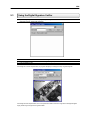
USING THE DIGITAL SIGNATURE VERIFIER ...........................................................................................104
BACKUP VIEWER............................................................................................106
10.1
10.2
10.3
BACKUP VIEWER OVERVIEW .................................................................................................................107
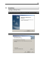
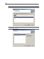
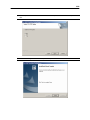
INSTALLATION ........................................................................................................................................108
LOADING VIDEO FROM CDROM OR HARD DRIVE ................................................................................111
EMERGENCY AGENT...................................................................................... 112
11.1
11.2
11.3
11.4
11.5
11.6
11.7
EMERGENCY AGENT OVERVIEW ...........................................................................................................113
INSTALLING THE EMERGENCY AGENT ...................................................................................................113
CONFIGURING THE DVR ........................................................................................................................114
CONFIGURING THE CLIENT PC ..............................................................................................................115
EMERGENCY AGENT WINDOW...............................................................................................................116
SEARCH ALARM WINDOW .....................................................................................................................117
CONFIGURATION WINDOW .....................................................................................................................118
WEB VIEWER ..................................................................................................120
12.1
12.2
12.3
12.4
WEB VIEWER OVERVIEW .......................................................................................................................121
CONFIGURING THE SERVER FOR REMOTE CONNECTION .....................................................................122
CONNECTING TO A DVR USING WEB VIEWER ......................................................................................122
CLOSING THE WEB VIEWER ..................................................................................................................122
REMOTE SOFTWARE ......................................................................................124
13.1
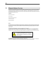
REMOTE SOFTWARE OVERVIEW ...........................................................................................................125
13.1.1 Remote Client Minimum Requirements .......................................................................................126
13.1.2 Remote Client Recommended Requirements ............................................................................126
13.2
REMOTE SOFTWARE SETUP ..................................................................................................................126
13.2.1 Installing Remote Software .............................................................................................................126
13.2.2 Create a New Remote Connection.................................................................................................127
13.3
REMOTE SERVER SETUP .......................................................................................................................128
13.3.1 Configuring the Server for Remote Connection ........................................................................128
APPENDIX A ...................................................................................................130
A1
A2
KV-DVR SPECIFICATIONS ....................................................................................................................131
KV-EVR SPECIFICATIONS.....................................................................................................................132
xiv
Preface
About this Guide
This manual is a setup and maintenance guide that can be used for reference when setting up
the DVR unit and for troubleshooting when a problem occurs. Only authorized personnel should
attempt to repair this unit.
Toshiba reserves the right to make changes to the DVR units represented by this manual
without notice.
The following text and symbols mark special messages throughout this guide:
WARNING: Text set off in this manner indicates that failure
to follow directions could result in bodily harm or loss of life.
CAUTION: Text set off in this manner indicates that failure to
follow directions could result in damage to equipment or loss
of information.
NOTE: Text set off in this manner indicates topics of interests that
can help the user understand the product better.
TIP: Text set off in this manner indicates topics and points of
interests that can be helpful when using or settings up the DVR unit.
Technician Notes
WARNING: Only authorized technicians trained by Toshiba should attempt to repair this DVR unit. All
troubleshooting and repair procedures that may be shown are for reference and minor repair only. Because of the
complexity of the individual components and subassemblies, no one should attempt to make repairs at the
component level or to make modifications to any printed wiring board. Improper repairs can create a safety hazard.
And any indications of component replacement or printed wiring board modifications may void any warranty.
WARNING: To reduce the risk of electrical shock or damage to the equipment:
•
•
•
Do not disable the power grounding plug. The grounding plug is an important safety feature.
Plug the power cord into a grounded (earthed) electrical outlet that is easily accessible at all times.
Disconnect the power from the computer by unplugging the power cord either from the electrical outlet or
the computer.
CAUTION: To properly ventilate your system, you must provide at least 3 inches (7.6 cm) of clearance at the front
and back of the DVR unit.
1
Introduction
What is a Surveillix® DVR™
A Surveillix DVR is simply a server that performs as a High Definition Digital Recorder. By
utilizing the many features of a computer, including processing power, storage capacity,
graphics compression, and security features, the DVR unit is more powerful than the analog
recorders of the past.
The Surveillix DVR server software comes pre-configured for fast and seamless integration
within your existing IT infrastructure. Designed around Microsoft® Windows® 2000, the server
software offers unparalleled stability, security, and ease of use. Accordingly, your security
investment has never been easier to maintain. Multiple users may simultaneously connect
through any network connection for instantaneous live viewing, digital search, and off site video
storage. Users can also connect remotely through DSL, Cable Modems, ISDN, or 56K dial-up.
This powerful software enables users to establish recording schedules, create motion detection
zones, use PTZ controls, and configure alarm inputs and outputs for each of the system's
cameras. With the latest advancements in the DVR Server Software, searching and indexing
your video archive has never been easier. Video can now be found, viewed, and exported in a
number of file formats with just a few clicks.
The Surveillix DVR is high performance security product ready to meet today’s security
demands.
2
New Features
Toshiba’s Surveillix DVRs include the following new features:
•
•
•
•
•
•
•
•
•
•
•
•
•
•
•
•
•
•
•
•
•
•
•
•
Optimized and Designed for Microsoft® Windows® 2000
Supports up to 16 Digital Control Outputs on Alarm Activation
Supports up to 16 Relay Inputs for Alarm Control
Remote System Operation & Configuration
Supports Multiple Simultaneous Remote Connections
PAN / TILT / ZOOM Controls
Simultaneous Video Search, Playback and Backup
Video Indexes for Easy Searching
Multiple Levels of Security Access
Up to 16 Looping Outputs
Up to 8 Audio Inputs
POS and ATM Support
1 Composite Output
S-Video Output
Up to 32 Camera Inputs
High Performance, Durable, Rackmount Chassis
Output the Video to a NTSC/PAL Display
Virtually Unlimited Storage Potential
Supports Digital Signature
Video Loss Alarm Functionality
Continuous, Motion Detection, Alarm, Pre-Alarm, and Scheduled Recording Modes
Hardware Watchdog
720x480 / 720x240 / 350x240 NTSC Recording Resolution
720x576 / 720x288 / 360x288 PAL Recording Resolution
3
4
4
C H A 3P T E R
2
1
DVR Description
This chapter includes the following information:
•
•
•
•
•
Input/Output connector locations
Front Panel Controls and LEDs
Rear Panel Connectors
Drive Positions
Serial Number Location
5
1.1
Basic Features
Surveillix™ state-of-the-art High Definition Digital Recorders are housed in a high performance
and versatile 4U Aluminum Rack-Mount case allowing easy storage of multiple DVRs for
enterprise applications. Every Surveillix DVR Unit comes equipped with the latest technology:
•
•
•
•
•
•
Intel® Pentium® IV Processor
10/100 Network Interface Card (NIC)
256 MB of System Memory
32 MB Video Card
CD-RW Recorder
Full Duplex High-Fi Sound Functionality
6
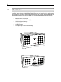
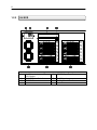
1.2
Front Panel Controls and LEDs
The front panel of the DVR unit contains the devices that will be commonly used for data
removal, retrieval, and backup replacement. The most common components and buttons are
shown below:
1.2.1
KV-DVR
1
2
3
Cooling Fan Air Intake
CD-RW Drive
CD-RW Open Tray Button
4
5
6
Hard Drive Array
ON/OFF Power Switch
Hard Drive Activity and Power LED
Display
7
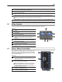
1.2.2
KV-EVR
1
2
3
Hard Drive Activity and Power
LED Display
ON/OFF Power Switch
CD-RW Drive
4
CD-RW Open Tray Button
5
6
Hard Drive Array
Cooling Fan Air Intake
8
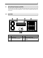
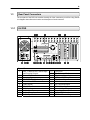
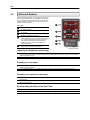
1.3
Rear Panel Connectors
The rear panel of the DVR unit contains virtually all of the connectors you will be using. Below
is a diagram that outlines the location and description of each connector:
1.3.1
KV-DVR
CH 1 in
CH 2 in
CH 3 in
CH 4 in
CH 5 in
CH 6 in
CH 7 in
CH 8 in
CH 9 in
CH 10 in
CH 11 in
CH 12 in
CH 13 in
CH 14 in
CH 15 in
CH 16 in
CH 1 Out
CH 2 Out
CH 3 Out
CH 4 Out
CH 5 Out
CH 6 Out
CH 7 Out
CH 8 Out
CH 9 Out
CH 10 Out
CH 11 Out
CH 12 Out
CH 13 Out
CH 14 Out
CH 15 Out
CH 16 Out
ON
OFF
1 C AM ERA 75
TER M 16
SEN
1
2
3
4
5
6
7
8
9
10
11 12
13 14
15
16
CON
1
2
3
4
5
6
7
8
9
10
11 12
13 14
15
16
COM 1
Figure 1.3
1
BNC Connector for Camera Input
and Looping Outputs
2
Sensor Inputs
3
Looping outputs
4
DB-15 SVGA Monitor Output
5
RCA Video OUT
6
Audio Inputs
7
RS-422 Interface
8
S-Video Output
9
Audio Line In
10 Audio Microphone In
11 Audio Speaker Out
COM 2
12
13
14
15
16
17
18
19
20
21
22
23
USB Ports
RJ-45 Network Jack
DB-9 Serial Input 1
LPT Parallel Printer Port
DB-9 Serial Input 2
USB Ports
PS/2 Keyboard Input
PS/2 Mouse Input
Control Alarm Outputs
Secondary Power switch
110V / 220V Switch
IEEE AC Power Adapter
9
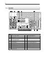
1.3.2
KV-EVR
CH 1 in
CH 2 in
CH 3 in
CH 4 in
CH 5 in
CH 6 in
CH 7 in
CH 8 in
CH 9 in
CH 10 in
CH 11 in
CH 12 in
CH 13 in
CH 14 in
CH 15 in
CH 16 in
CH 1 Out
CH 2 Out
CH 3 Out
CH 4 Out
CH 5 Out
CH 6 Out
CH 7 Out
CH 8 Out
CH 9 Out
CH 10 Out
CH 11 Out
CH 12 Out
CH 13 Out
CH 14 Out
CH 15 Out
CH 16 Out
CH 17 in
CH 18 in
CH 19 in
CH 20 in
CH 21 in
CH 22 in
CH 23 in
CH 24 in
CH 25 in
CH 26 in
CH 27 in
CH 28 in
CH 29 in
CH 30 in
CH 31 in
CH 32 in
CH 17 Out
CH 18 Out
CH 19 Out
CH 20 Out
CH 21 Out
CH 22 Out
CH 23 Out
CH 24 Out
CH 25 Out
CH 26 Out
CH 27 Out
CH 28 Out
CH 29 Out
CH 30 Out
CH 31 Out
CH 32 Out
ON
ON
OFF
OFF
1C
AME
RA
75
TERM 16
C
RA
17 AME
75
TERM 32
CON
SEN
C 1
OM
Figure 1.3
1
110V / 220V Switch
2
Secondary Power switch
3
IEEE AC Power Adapter
4
BNC Connector for Camera Input
and Looping Outputs
5
Looping outputs
6
Sensor Inputs
7
RCA Video OUT
8
Audio Inputs
9
RS-422 Interface
10 DB-15 SVGA Monitor Output
11 S-Video Output
12 Audio Line In
C 2
OM
13
14
15
16
Audio Microphone In
Audio Speaker Out
USB Ports
RJ-45 Network Jack
17
18
19
20
21
22
23
DB-9 Serial Input 1
LPT Parallel Printer Port
DB-9 Serial Input 2
Control Alarm Outputs
USB Ports
PS/2 Keyboard Input
PS/2 Mouse Input
10
11
C H A P T E R
Getting Started
This chapter includes the following information:
Included Components
Setting up your DVR Hardware
Optional Components
12
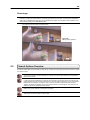
2.1
Identifying included components
Surveillix™ DVRs come with a mouse, keyboard and selected software and cables. Identify the following components
to make sure everything has been properly included with your new DVR unit. If any of the following items are missing,
contact your dealer to arrange a replacement.
Included Component List:
1.
2.
3.
4.
5.
6.
7.
8.
9.
10.
11.
DVR Unit
Mouse
DVR Key
Manual
Repair CD
Software Installation CD
Keyboard
PTZ Adapter
RCA to BNC Adapter
Rackmount Attachments with Screws
Power Cable
1
2
3
4
5
6
7
8
9
10
11
Manual
13
2.2
Keyboard Setup
To attach the keyboard to the DVR unit, plug the end of the Keyboard into the keyboard PS/2 Port located on the back
of the machine. The keyboard PS/2 Port can be identified by the purple color. Refer to the Rear Panel Connectors
diagram for more information.
2.3
Mouse Setup
To attach the mouse to the DVR unit, plug the end of the mouse into the mouse PS/2 Port located on the back of the
machine. The mouse PS/2 Port can be identified by the green color. Refer to the Rear Panel Connectors diagram for
more information.
The mouse uses a cursor called a pointer. Pointers come in many different shapes but are most commonly shaped like
an arrow.
Your mouse has two buttons: a left button and a right button. Quickly pressing and releasing one of these buttons is
called clicking. Sometimes you will need to double-click – or click the same button twice quickly.
In this manual, click means to position your mouse point on an icon and to single click the left button. When a right click
is required, this is stated clearly. Double-click also refers to the left button.
The ratchet wheel in between the two buttons is added to provide easier scrolling capability. By simply moving the
wheel with your index finger, you can quickly move through multiple pages, line, or windows. The wheel may also
function as a third button allowing you to quickly click or double-click an icon or a selected item.
2
3
1
Figure 2.3
Figure 2.3
1
Left Button
2
Scroll button / Third Button
3
Right Button
14
2.4
Monitor Setup
Attach the Monitor to the Rear of the DVR unit using the VGA cable supplied by the Monitor Manufacturer. Refer to
your monitor manual for detailed information on how to setup and use it.
NOTE: The monitor you use must be capable of having a screen resolution of 1024 x 768 and display colors of at least 24 Bit
2.5
Power Setup
Attach the AC power cable to the rear of the DVR Unit. See Rear Panel Connectors for more information.
WARNING: To reduce the risk of electrical shock or damage to the equipment:
•
•
•
2.6
Do not disable the power grounding plug. The grounding plug is an important safety feature.
Plug the power cord into a grounded (earthed) electrical outlet that is easily accessible at all times.
Disconnect the power from the computer by unplugging the power cord either from the electrical outlet or the
computer.
Connecting a Video Source to the DVR
There are different types of Video Sources that can be plugged into your DVR unit including DVD players, VHS players,
and CCTV Cameras. The back of the DVR unit contains up to 16 video inputs depending on the DVR model. The
connectors use the BNC standard. On the KV-PCDVR32 32 Channel DVR, all 32 of these ports are used as inputs.
Video Inputs – The Video inputs are RG-59 BNC connectors. Simply plug one end into your video source (DVD,
Camera, etc.) and plug the other end into the desired BNC input on the DVR unit.
2.7
Looping Output Termination
When terminating the outputs becomes necessary, the DVR unit has built-in termination that allows you to select
individual outputs to be terminated. Generally it is not necessary to terminate the output when using it. It is dependant
on if the device to which you are connecting it, has internal 75 ohm termination. As a rule, if the image appears
distorted or virtually unviewable, it most likely needs to be terminated.
Terminating
the Looping
Outputs
ON
Not connected to a
monitor (Normal)
OFF
Connected to a
monitor
(Looped)
Always leave the dipswitch set to the ON position when the Looping Outputs are not used.
15
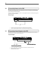
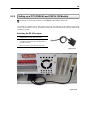
2.8
Connecting Sensors to the DVR
Each DVR unit may have up to 16 Sensor inputs. These inputs can be used with devices such as Infrared devices,
motion devices, glass breakage alarms, door and window trips, and many more. The Sensors can be set to Normally
Open or Normally Closed inside the software.
There are 4 Commons (-) and 16 inputs (+). There is no power supplied to the ports so an external power supply must
be used if power becomes necessary.
Sensor Input
COM
•
•
2.9
Sensor (1 ~ 16)
Normally Open or Normally Closed option is available inside the DVR Software.
There is no power supplied to the ports. Use an external power supply if necessary.
Connecting Control Outputs to the DVR
Each DVR unit may have up to 16 Control Outputs. These outputs can be used to trigger devices such as Sirens,
Phone Dialers, Lights, and any other relay activated device.
Control Output
Control Out (1 ~ 16)
COM
(-)
(+)
Siren, Alarm, Outside Relays
External Power Supply ( DC 12V)
•
•
•
Use 12V, below 300mA. For controlling lights or other devices, use another external relay.
Maximum voltage is 24V AC @ 1 amp
Output uses a Form C Relay
16
2.10
Looping Outputs
The 8 and 16 Channel DVR units may have up to 16 Looping outputs. Depending on the destination of the
outputs, each output may have to be terminated (See section 2.10).
Looping Outputs – The Video inputs are RG-59 BNC connectors. Make sure there is a video source connected
to the input and then connect a cable to the Channel Out. The looping outs can be connected to video monitors or
combined with adapters to connect to VCR’s.
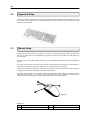
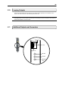
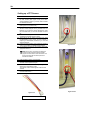
2.11
Additional Outputs and Connectors
4
Signal Line
Grou
Signal Line
RX LED
TX LED
Operation
LED
17
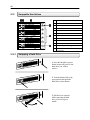
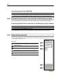
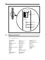
2.12
Swappable Hard drives
1
Handle Release Button
Press Button to eject the Release Handle.
LOCK
OPEN
2
Button Lock
Locks the Handle Release button.
LOCK
3
Pull to Eject the Hard Drive.
OPEN
4
LOCK
Reset Button
Resets the hard drive unit
OPEN
5
Power Buttons
Turns the power on or off to a hard drive.
LOCK
OPEN
Release Handle
6
Temperature Alarm Light
Turns on if a Hard Drive reaches a set
temperature.
2.12.1
Swapping a Hard Drive
1. Press the hard drive power
button to turn off power to the
hard drive you wish to
remove.
2. Turn the button lock to the
open position and push the
hard drive release button.
3. Pull the lever outward
while removing the hard
drive. Reverse steps to
install.
18
2.13
Monitor Setup
There are up to 2 available connections for monitors which can be used individually or in tandem.
SVGA Output
To VGA Monitor.
S-Video Output
To TV/VCR.
Attach the Monitor or Monitors to the Rear of the HDDR unit using the cable supplied by the Monitor
Manufacturer. Refer to your monitor manual for detailed information on how to setup and use it.
NOTE: The monitor you use must be capable of having a screen resolution of 1024 x 768 and display
colors of at least 32 Bit
19
2.14
Optional Components
To fully utilize your DVR unit’s potential, several optional Surveillix components are listed below. Contact your dealer for
more information.
Extra Video Storage Hard Drive – Each DVR unit has a virtually unlimited storage potential. By adding additional
Video Data Hard Drives you can extend the amount of Video Data your DVR system can store before overwriting
older data.
2) NP-FM56USB
56K External Modem – This 56K modem allows you to connect the DVR to a standard
phone line. Using this modem you can either connect the unit to the Internet or allow a direct DVR to computer
connection.
3) PW-UPS
UPS Power Backup – UPS Power Backups allow your DVR unit to remain fully functional even in the
event of a power failure. UPS Power Backups also even the fluctuating power current out to provide a consistent,
reliable power flow. This creates a stable environment for the DVR unit and reduces failure.
4) NP-4PKVM 4 Channel KVM Switch – The 4 Channel KVM switch allows you to have multiple boxes (up to 4)
using only one keyboard, mouse and monitor. You can simply switch between the DVR units using the keyboard.
5) Hot Swappable Redundant Power Supplies – Every DVR and EVR has the option of a dual redundant hot
swappable power supply. In the event of a component failure the inoperable power supply may be removed
leaving the DVR running so no break in recording occurs. Simply replace the power supply with a new one and
you are finished.
6) Raid Controller – A raid controller is available for increased performance or data reliability.
7) MO-F50L 15” LCD Monitor – 15” Flat screen monitor.
8) MO-F70L 17” LCD Monitor – 15” Flat screen monitor.
9) MO-T17
17” CRT Monitor – 17” Standard CRT monitor.
10) MO-T19
19” CRT Monitor – 19” Standard CRT monitor.
1)
20
C H A P T E R
DVR Basics
This chapter includes the following information:
•
•
•
Turning the DVR on and off
Becoming familiar with the Display screen
Defining Screen Divisions
21
3.1
Turning on the DVR
Once the cables and adapters have been properly connected (See Chapter 2) it is time to turn on the power. To turn on
the power follow these steps:
Turning the DVR unit ON
1)
2)
3)
Turn on the monitor and any external peripherals (ex. Printers, External Storage Devices, etc.) connected to the
DVR unit.
Turn on the Secondary Power Switch located in the rear of the DVR unit.
Turn on the main power switch located on the front of the DVR unit.
The DVR will run a series of self-tests. After two or three minutes a series of messages may be displayed as the
various hardware and software subsystems are activated. Under normal circumstances you should not be asked
to respond to these messages. If you are asked to respond to the messages (adding a Printer, Monitor, etc for the
first time) follow the instructions carefully.
After this finishes, the Surveillix DVR software should load automatically and bring you to the main screen.
3.2
Turning off the DVR
Turning the DVR unit OFF
1)
To turn off the DVR unit, select the Exit button from the main screen. This will prompt you whether you wish to exit
the program or not. Select yes. The DVR unit will shut itself off automatically once this is done. The DVR unit may
take several minutes to shut down completely.
CAUTION: Always be sure to follow the proper procedures when turning off the power to the DVR unit. NEVER
disconnect the power to the DVR unit while it is still running or in the process of shutting down. Doing so can cause data
loss, file corruption, system instability and hardware failure.
22
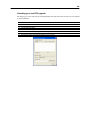
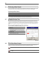
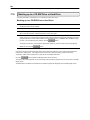
3.3
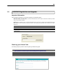
HVR/NVR Registration and Upgrade
Important Information
Have the following information on hand before registering your NVR/HVR upgrade
NVR/HVR Software Serial Number: The Product Serial Number is the unique number that Toshiba provided
with your purchased software.
System ID: The System ID is a number generated by the unit. This is a unique code generated using the
MAC address of the computer running the software. The following steps illustrate how to obtain your unique
System ID.
1) Enter Setup
2) Click Camera Setup
3) Click the Registration button
4) In the Network Device Authentication, the System ID can be located under the “Add a new Serial Key” section
(shown below)
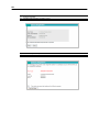
Obtaining your Unlock Code
The following steps are provided to assist in registering the NVR/HVR upgrade
1)
2)
3)
4)
Open an Internet browsing software and go to
http://registration.surveillixdvrsupport.com/toshiba/Registration/registration.aspx
Enter the Product Serial Number that was provided by Toshiba
Enter the System ID that was generated by your unit
Click Submit
23
5)
6)
Verify the Information
Click Next if the information provided is correct
7)
8)
Once validated, you will be provided with the Unlock Code
Print the page and save for later reference
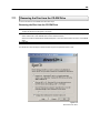
24
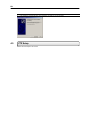
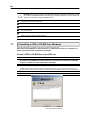
Unlocking your new network device
After obtaining your unlock code from the Toshiba Registration Site, follow theses steps to unlock your new upgrades
on your Surveillix DVR.
1)
2)
3)
4)
5)
6)
7)
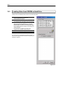
3.4
Start your Surveillix DVR
Enter Setup
Enter Camera Setup
Click the Registration button
Enter the Unlock Code generated by the Toshiba Registration Site into the “new serial number” field
Click Add a serial number
Once the new serial number has been added to the list, click OK
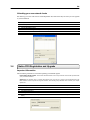
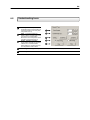
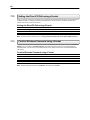
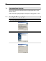
Native POS Registration and Upgrade
Important Information
Have the following information on hand before registering your NVR/HVR upgrade
POS Software Serial Number: The Product Serial Number is the unique number that Toshiba provided with
your purchased software.
System ID: The System ID is a number generated by the unit. This is a unique code generated using the
MAC address of the computer running the software. The following steps illustrate how to obtain your unique
System ID.
1)
2)
3)
4)
5)
6)
Enter Setup
Click General
Click POS Setup
Click Setup POS Agent
Click Registration
In the POS Authentication, the System ID can be located under the “Add a new Serial Key” section (shown
below)
25
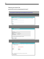
Obtaining your Unlock Code
The following steps are provided to assist in registering the NVR/HVR upgrade
Note: This process is the same as the HVR/NVR Registration and Upgrade
1)
2)
3)
4)
Open an Internet browsing software and go to
http://registration.surveillixdvrsupport.com/toshiba/Registration/registration.aspx
Enter the Product Serial Number that was provided by Toshiba
Enter the System ID that was generated by your unit
Click Submit
5)
6)
Verify the Information
Click Next if the information provided is correct
7)
8)
Once validated, you will be provided with the Unlock Code
Print the page and save for later reference
26
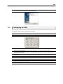
Unlocking your new POS upgrade
After obtaining your unlock code from the Toshiba Registration Site, follow theses steps to unlock your new upgrades
on your Surveillix DVR.
1)
2)
3)
4)
5)
6)
7)
8)
Start your Surveillix DVR
Enter Setup
Enter General
Click the POS setup button
Click the Setup POS Agent button
Enter the Unlock Code generated by the Toshiba Registration Site into the “new serial number” field
Click Add a serial number
Once the new serial number has been added to the list, click OK
27
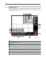
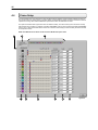
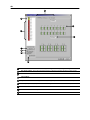
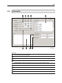
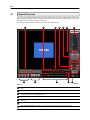
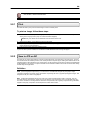
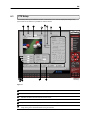
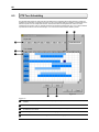
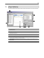
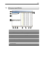
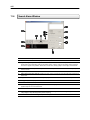
3.5
Display Screen
Each time the DVR is restarted, the program defaults to the Display screen. The following diagram outlines the buttons
and features used on the Display screen. You should become familiar with these options as this is the screen that will
be displayed the majority of the time.
1
2
3
4
5
6
7
8
9
15
14
13
10
12
11
Figure 3.3
Figure 3.3
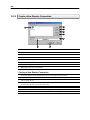
1
3
Exit Button – The exit button brings up several options, including Shut Down, Restart, Log On, Log Off and
Restart in Windows Mode.
Log In / Log Out – This button Logs the current user off and allows you to Log in using a different user
account.
Setup – This Brings up the setup menu from which all customizable settings can be edited.
4
PTZ – Opens the PAN / TILT options for controlling PTZ enabled Cameras.
5
Backup Button – Brings up the Backup options.
6
Search Button – Displays search features that allow you to search through previously recorded video.
7
Current User – Displays the name of the user currently logged in to the DVR.
8
Network Information – Displays whether a Remote User is logged in.
2
28
9
Remote User Display – Displays the users connected to the DVR.
10
Instant Replay – This button is a shortcut that instantly jumps into Search Mode and begins playing the video
backwards.
Date/Time – Displays the current time and date. This date and time is stamped into the recorded video and is
displayed whenever the video is played back.
Sensor Status Bar – Displays the Sensor status for each camera that is setup to use Sensors.
11
12
13
14
15
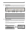
3.6
Control Output Status and Activation Bar – The Relay buttons fire the Output Relays. The Output Relays
can be hooked up to external alarms, set to trigger an audio alarm, send a phone call, etc.
Screen Division Buttons – The Screen Division buttons allow you to view one or more sets of cameras at a
time.
Full Screen – Displays the video full screen.
Loop – Pressing the Loop button sequences through the Screen Divisions sets. For Example, selecting the 1A
and then the Loop button will sequence through 1A,2A,3A,4A and then repeat. This option is not available for
the 7,10 and 13 screen divisions.
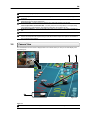
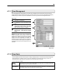
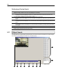
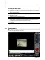
Camera View
The Cameral status for each camera is displayed next to the Camera number (or name) on the Video Display Area.
The following are
2
3
IIIN
N
S
T
A
N
T
NS
ST
TA
AN
NT
T
1
Figure 3.4
Figure 3.4
1
Camera Number and Name – Displays the camera number and the custom name given to the camera.
29
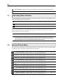
3.7
2
Recording Status – Displays the current recording status of the camera using symbols. (See Section 3.5)
3
Special Recording – Displays text relating to the type of recording that is occurring. (See Section 3.5)
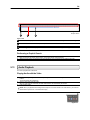
Recording Status Indicator
The Camera status for each camera is displayed next to the Camera number (or name) on the Video Display Area. The
following are the different states for each camera:
Recording – A red light is displayed when the camera is currently being recorded to the DVR unit.
Motion Detection – A green light is displayed when a camera (set up for motion detection) detects motion.
Display – This is displayed when the camera is currently not being recorded to the DVR unit.
There are several different types of DVR ‘Special Recording’. When this happens text is displayed on the camera
indicating what kind it is. These are as follows:
SENSOR – Sensor is displayed when a sensor, associated with a given camera, is activated.
INSTANT – Instant Recording is a manual activation of the recording for the selected camera. Regardless of
the recording method, Instant Recording will start the camera recording and also flag the video for future
searches using the Index Search feature. INSTANT is displayed when a user activates the instant recording
option. Double Right-Click to activate and deactivate the Instant Recording option.
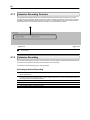
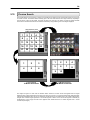
3.8
Screen Division Menu
The Screen Division menu allows you to view cameras full screen by rotating one by one, four by four, eight by eight or
by viewing four, eight or 16 at a time. The button options are shown below.
1st Four Cameras View – Displays cameras 1-8 in the Video Display Area. To return to a different MultiCamera View, select a different Screen Division option from the Camera View Option.
2nd Four Cameras View – Displays cameras 5-8 in the Video Display Area. To return to a different MultiCamera View, select a different Screen Division option from the Camera View Option.
3rd Four Cameras View – Displays cameras 9-12 in the Video Display Area. To return to a different MultiCamera View, select a different Screen Division option from the Camera View Option.
4th Four Cameras View – Displays cameras 13-16 in the Video Display Area. To return to a different MultiCamera View, select a different Screen Division option from the Camera View Option.
5rd Four Cameras View – Displays cameras 17-20 in the Video Display Area. To return to a different MultiCamera View, select a different Screen Division option from the Screen Division menu.
6th Four Cameras View – Displays cameras 21-24 in the Video Display Area. To return to a different MultiCamera View, select a different Screen Division option from the Screen Division menu.
7rd Four Cameras View – Displays cameras 25-28 in the Video Display Area. To return to a different MultiCamera View, select a different Screen Division option from the Screen Division menu.
8th Four Cameras View – Displays cameras 29-32 in the Video Display Area. To return to a different MultiCamera View, select a different Screen Division option from the Screen Division menu.
1st Eight Cameras View – Displays cameras 1-9 in the Video Display Area. To return to a different MultiCamera View, select a different Screen Division option from the Screen Division menu.
30
2nd Eight Cameras View – Displays cameras 10-16,8,9 in the Video Display Area. To return to a different
Multi-Camera View, select a different Screen Division option from the Screen Division menu.
1st Sixteen Cameras View – Displays cameras 1-8 in the Video Display Area. To return to a different MultiCamera View, select a different Screen Division option from the Screen Division menu.
2nd Sixteen Camera View – Displays cameras 9-16 in the Video Display Area. To return to a different MultiCamera View, select a different Screen Division option from the Screen Division menu.
Multi-Camera View – Displays a group of cameras within the Video Display Area.
Multi-Camera View – Displays a group of cameras within the Video Display Area.
Multi-Camera View – Displays a group of cameras within the Video Display Area.
Full Screen – The Full Screen Option allows you to view the Video Display Area using the entire viewable area
on the monitor. When this is selected, no menu options are visible. You can activate the Full Screen Option by
clicking on the Full Screen Button within the Screen Division Menu. You can deactivate Full Screen mode by
right clicking on the screen.
Loop – Pressing the Loop button rotates through the Screen Divisions.
31
C H A P T E R
Setup Options
This chapter includes the following information:
•
•
•
•
•
•
•
•
•
Setup Overview
Channels
Color
Schedule
Speed
Motion Detect
Password
Pan/Tilt
Audio
32
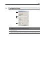
4.1
Setup Overview
The Setup options allow you to optimize your DVR unit by adjusting things like camera names, reboot schedules,
recording schedules and more. It is extremely important that you setup your DVR correctly for several reasons.
•
•
•
•
4.1.1
Recording Schedules – By optimizing the recording schedule you can increase the amount of pertinent
recorded video that is saved on the DVR and keep it longer. You can optimize the type of recording done by
adding motion detection to this as well, again increasing the amount of useful video.
DVR Access – By setting up the access passwords you can tightly control the types of access an individual
may have. This ensures the security and integrity of the DVR unit.
Camera Naming – By naming each camera you can easily identify the location and any other pertinent
information that may be helpful simply by viewing it on the Video Display Area.
Adjusting Camera Color – By adjusting each camera’s color settings you can optimize the clarity and detail
that is recorded.
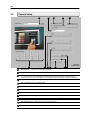
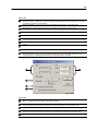
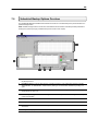
Setup Screen Overview
Figure 4.1.1
Figure 4.1.1
1
Setup Options – Allows you to toggle between different setup screens.
1
33
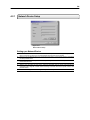
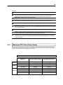
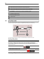
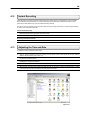
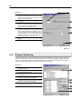
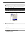
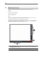
4.2
Camera Setup
1
3
2
4
5
11
6
10
12
9
10
8 7
Figure 4.2
Camera Setup
1
Select Camera – Selects the current camera to be edited.
2
Camera Name – Allows you to specify a name for each camera.
3
4
Sensor Connections – Allows you to attach one or more sensor connections to each camera.
You can connect one or more Sensors to the selected camera by checking the box next to the sensor(s).
Connecting a sensor to the camera allows you to activate both Standard Recording and Intensive Recording
Bright – Adjusts the Brightness of the selected camera.
5
Hue – Adjusts the Hue of the selected camera.
6
Contrast – Adjusts the Contrast of the selected camera.
7
Adjust Default – Adjust the color settings for the selected camera back to the System default.
8
Adjust All Default – Adjusts the color settings for ALL cameras to the System default.
9
Apply to all channels – Applies current settings to ALL cameras.
10
Setup Network Device – Sets up a Network Device from a specified address.
11
Use Network Device – Enables setup and use of a Network Device.
12
Enable Network Device PTZ – Enables the use of a Network Device PTZ.
34
4.2.1
Network Device Setup
Figure 4.2.1
Network Device Setup
Setting up a Network Device
1)
2)
3)
4)
5)
6)
Check the Use Network Device Box, once selected the Setup Network box will appear. If your Network
Device is setup for use with a PTZ, the Enable Network Device PTZ may be selected.
Now that your Use Network Device box is selected, begin setting up the network device by left clicking
the Setup network button.
Once in Network Device Properties, select setup to configure the IP address and port number of the
desired network device.
STEP 1: Enter the Network Device IP address, the connection port number and click next.
STEP 2: From the Class pull down menu, select the appropriate class of camera. After selecting the
appropriate class, designate a model number and assign a channel name for the specific camera. Click
the Finish button.
STEP 3: Click configure to further configure the specific camera options.
35
4.3
Motion
2
1
4 5 6 7
8
3
12 13
3
9
10 11
Figure 4.3
1
Select Camera – Selects the current camera to be edited.
2
Sensitivity – Adjusts the sensitivity within the designated Motion Areas.
3
Clear – Clears all Motion Areas for the selected camera.
4
Regular Interval Recording – This option allows you to record a single frame every few minutes or every few
hours to show that the DVR is still functioning even when motion is not taking place. This option only works
when Motion recording or Sensor recording is selected.
Full Screen Pop-Up on Sensor – When Sensor (alarm input) is detected, the camera will display full screen.
The video will not atomically return to normal view. This option will require a user reset the screen to normal
view.
Beep on Detect – When motion is detected, an internal speaker on the DVR will sound an alarm.
5
6
7
8
Full Screen Pop-Up – When Motion is detected, the camera is displayed full screen. The video will not
atomically return to normal view. This option will require a user reset the screen to normal view .
Alarm Output – Allows you to activate a specified control output when Motion is detected.
36
9
11
Post Alarm (SENSOR) – Allows you to record video after a Sensor event has ceased for a specified period of
time. This option will only work for cameras set to record from a Sensor Event.
Post Alarm (MOTION) – Allows you to record video after Motion has stopped for a specified period of time.
This option will only work for cameras set to record using Motion Detection
Pre-Alarm – Allows you to record a section of video just prior to Motion or Sensor activation.
13
Full Motion Area – Allows you to set the whole screen as a full motion region.
14
Apply to All Channels – Takes the current settings and applies it to all channels.
10
4.3.1
Creating a Motion Area
Creating a Motion Area
1)
2)
Place the mouse pointer at the upper left hand corner of the
area you want to designate, press and hold down the left
mouse button, drag the mouse. Let go of the button when the
Motion Area is the size you want it to be.
Continue creating as many Motion Areas as you wish (up to 5).
You can resize them and move them by dragging the sides and
corners of the Motion Area.
Figure 4.3.1
4.3.2
Activating an Alarm Output on a Motion Event
Enabling Alarm Output on a Motion Event
1)
2)
3)
4)
5)
From the Motion Setup window, select a camera to edit.
Configure the camera for Motion.
Check the Alarm Output box.
Select a Control Output to activate for the selected camera.
Select the duration you wish the Control Output to be activated
for. When a Motion event occurs.
Figure 4.3.2
37
4.4
Frame Setup
The Frame Setup menu gives the user the option to adjust both the resolution and the number of images per second
each camera will record. When setting up the PPS sliders, the BLUE slider represents the frames in which the DVR will
capture the incoming video while the RED slider represents the frame rate that will be recorded.
This option is beneficial when higher frame rates are desired remotely. The Server will only send out frames remotely
that have first been encoded. For example, If the Blue ‘ENCODING’ option is set to 25 PPS and the Red ‘RECORDING’
option is set to 7 PPS then the DVR Server will record 7 PPS and users viewing live video remotely will receive 25 PPS
on that specific camera.
NOTE: The RED FPS record slider cannot exceed the BLUE FPS capture slider.
1
2
3
4
5
6
7
8
9
Figure 4.4
38
Figure 4.4
1
Set Default – Selecting this option resets all camera Frames and resolutions to the default settings.
2
Frame Status – Displays the layout and order of the frames being recorded. The Frame Status represents a
One Second period of time with 240 colored blocks inside. Each block represents one frame and each color
represents a camera. (See Camera Number) The layout shows the recording order for each second.
Video Format – Displays the Video Format (NTSC/PAL).
3
4
Camera Number – The cameras are given different colors to help distinguish themselves when viewing the
Frame Status. You can adjust the recorded Frames per Second by sliding the bar to the left and right.
5
Number of Frames – Displays the number of frames that are selected for each camera.
6
Frame Select – Adjusts the frames for each camera. The blue slider designates the number of frames a second
that can be captured by the selected camera, while the red slider designates how many frames can be recorded
by the designated camera.
7
Resolution – Displays the available Resolution options.
8
Quality – This setting affects the quality of the video. Increasing the quality of the camera can reduce the
amount of pixilation within the image considerably, but also increases the file size.
Sensitivity – The Sensitivity adjusts the rate at which the Keyframe refreshes. This option directly affects the
codec being used to record the video. Adjusting this setting can have drastic negative effects on the quality of
the video. It is highly recommended that this setting always be left at the default setting unless so instructed by
a system administrator.
9
4.4.1
Maximum PPS Table (Frame Setup)
The frame setup is limited to how many PPS can be assigned to a group of cameras. IE: A 16 channel unit that can
capture a total of 240 PPS is limited to a total of 120 PPS in the first 8 channels and 120 in the last 8 channels. Below is
a chart of the total PPS that can be captured per channel group.
340 X 240 Resolution
16 CH
32 CH
64 CH
Channels
240 PPS Capture Card
480 PPS Capture Card
1 – 8
8 – 16
1 – 16
17 – 32
1 – 16
17 – 32
13 – 48
49 – 64
120 PPS
120 PPS
120 PPS
60 PPS
60 PPS
60 PPS
60 PPS
120 PPS
240 PPS
240 PPS
240 PPS
120 PPS
120 PPS
120 PPS
120 PPS
240 PPS
39
40
4.5
Schedule Setup (Recording)
The Recording Schedule Window allows you to create different recording schedules based on the day, time, and type
of recording you wish to use. In addition this window also contains the System Restart options that allow you to perform
basic system maintenance by automatically scheduling the DVR to restart itself periodically
1
3
2
4
5
6
7
11
9
10
8
Figure 4.5
Recording Schedule
Figure 4.5
1
Recording – Toggles to the Recording Window (default).
2
3
Sensor – This option allows the user to toggles to the Sensor Window. This window allows you to create
schedules for the sensors attached to the DVR.
Day of the Week – Selects the day of the week for the schedule being made.
4
Single Selection Mode – Selects all days of the week at once.
5
Special Day Recording – Allows you to create special recording schedules for specific days.
6
Recording Schedule Window – Displays and allows you to edit the current Recording Schedule.
7
Recording Mode – Selects the Recording Mode. The Recording Modes are ‘NO RECORDING’ ‘CONTINUOUS
RECORDING’ and ‘MOTION RECORDING’.
41
8
Emergency Time – Specifies the amount of time (in seconds) to transmit the video in the Emergency Agent
Software.
Emergency IP – Specifies the IP Address to the send the Emergency Agent video to.
9
10
11
4.5.1
Event – Allows you to define Motion as an Alarm Event, whether to transfer the Alarm Event to the SMS Multisite Software, and/or whether to send the video to the Emergency Agent software.
Use – Allows the user to define which Emergency IP Addresses will be alerted.
Schedule Setup (Sensor)
1
3
2
4
5
6
7
11
9
8
10
Figure 4.5.1
Sensor Schedule
Figure 4.5.1
1
Recording – Toggles to the Recording Window (default).
2
3
Sensor – Toggles to the Sensor Window. This window allows you to create schedules for the sensors attached
to the DVR.
Day of the Week – Selects the day of the week for the schedule being made.
4
Single Selection Mode – Selects all days of the week at once.
5
Special Day Recording – Allows you to create special recording schedules for specific days.
42
6
Recording Schedule Window – Displays and allows you to edit the current Recording Schedule.
7
Enable/Disable – Enabled the selected Sensor for the time period specified.
8
Emergency Time – Specifies the amount of time (in seconds) to transmit the video in the Emergency Agent
Software.
Emergency IP – Specifies the IP Address to the send the Emergency Agent video to.
9
10
11
4.5.2
Event – Allows you to define Motion as an Alarm Event, whether to transfer the Alarm Event to the SMS Multisite Software, and/or whether to send the video to the Emergency Agent software.
Use – Allows the user to define which Emergency IP Addresses will be alerted.
Creating a Recording Schedule (Motion and Continuous)
Creating a Recording Schedule Based on Motion & Cont
1)
2)
3)
4.5.3
Select the Schedule Menu option.
Select a single day to begin creating the schedule for -or- Select the SINGLE SELECTION MODE button to create
the schedule for all the days of the week at once.
Highlight the time-blocks within the Recording Schedule Window for the camera(s) you wish to schedule. Once the
desired Time-Blocks are highlighted, press a RECORDING MODE button.
The Time-Blocks should now appear Blue for Motion, Yellow for Continuous and White for No Recording.
Creating a Recording Schedule (Sensor)
Creating a Recording Schedule Based on a Sensor Alarm
1)
2)
3)
Select the Schedule Menu option and press the SENSOR button. This will open the Sensor Recording Schedule
Window.
Select a single day to begin creating the schedule for -or- Select the SINGLE SELECTION MODE button to create
the schedule for all the days of the week at once.
Highlight the time-blocks within the Recording Schedule Window for the Sensor(s) you wish to enable and
schedule. Once the desired Time-Blocks are highlighted, press the ENABLE button.
The Time-Blocks should now appear Red.
The Sensors will supersede all other types of recording modes (MOTION, CONTINUOUS, NO RECORDING). This
means that regardless of what the cameras are currently set to, if a Sensor Event occurs and it is linked to one or more
cameras, the linked cameras will begin recording as a Sensor Event. Sensor Recordings will be ‘flagged’ and will be
easily searchable using the Index Search Mode option.
You can associate cameras to Sensors inside the CAMERA SETUP menu.
4.5.4
Scheduling Alarm Events
You can designate Motion or Sensor Events to be ‘Alarm’ events. Often times you may not want motion to be treated as
an Alarm event. For Example: During work hours Motion that occurs is expected and would not want to be treated an
as Alarm. However, after business hours are over, any motion that occurs should be treated as an Alarm.
There are three different types of Alarm Events:
ALARM EVENT:
CENTRAL STATION:
EMERGENCY AGENT:
This option logs the Alarm Events on the local server.
This option sends the Alarm Events to Central Station software.
This option sends the Alarm Event to the Emergency Agent software.
43
Scheduling Alarm Events (MOTION)
1)
2)
4.5.5
Select the Schedule Menu option. (Select either RECORDING or SENSOR)
Highlight any schedule that has been set to MOTION (or SENSOR) and press one of the EVENT button (ALARM
EVENT, CENTRAL STATION, EMERGENCY AGENT). A letter should now be placed within the select time.
Scheduling Alarm Events to send video to the Emergency Agent
You can designate Motion or Sensor Events to send video from Alarm Events to the Emergency Agent software.
Scheduling Alarm Events to send video to the Emergency Agent Software
1)
2)
3)
Enable an Emergency Agent Event (See SCHEDULING ALARM EVENTS).
Enter an IP address to send the video to into the IP ADDRESS field. (Only one IP address is supported)
Enter the duration inside the EMERGENCY TIME field.
See the EMERGENCY AGENT chapter for detailed information on setting up the Emergency Agent software.
4.5.6
Special Day Schedule
You can create days that have a unique recording schedule. You may wish to create these on days that are ‘not typical’
such as Holidays, Special Events, etc.
Figure 4.5.6
1
2
Special Day (Enter/Exit Edit Mode) – Enters / Exits the Special
Day Mode. Once in Special Day Mode you can create, edit and
delete Special Days.
Calendar – Displays the current day in a red circle.
3
Special Day Schedules – Displays the current saved.
4
Save Special Day – Saves the selected Special Day Schedule.
5
Delete Special Day – Deletes the selected Special Day Schedule.
1
2
3
4
5
Figure 4.5.6
Special Day
44
4.5.7
Creating and Editing a ‘Special Day’ Schedule
Creating a ‘Special Day’ Schedule
1)
2)
3)
4)
Press the ‘NORMAL DAY MODE’ button to enable the ‘SPECIAL DAY MODE’.
Select a day from the calendar by clicking on the CALENDAR drop down list.
Highlight the time-blocks within the Recording Schedule Window for the camera(s) you wish to schedule. Once the
desired Time-Blocks are highlighted, press a RECORDING MODE button.
When you have finished creating the schedule press the ‘SAVE SPECIAL DAY’ button. The special day should
now appear as a date within the Special Day Schedules.
Deleting a ‘Special Day’ Schedule
5)
4.6
Select a Special Day from the Special Day Schedules List and press the ‘DELETE SPECIAL DAY’ button.
Sensor
The Sensor Window allows you to enable, disable and configure Sensors.
1
2
3
Figure 4.6
Figure 4.6
Sensor
1
Type – Selects whether the Sensor will be Normally Open (NO) or Normally Closed (NC).
2
Delay (sec) – Adjusts the amount of time (in seconds) to ignore the sensor if it is continuously activated.
3
Relay – Selects the Control Output to activate once the Sensor has been tripped.
45
4.7
General
1
Figure 4.7
1
2
3
4
5
6
7
8
9
3
5
4 6 7
2
8
9
12 11 10
Voice Warning – Allows you to use an audible warning (.wav Sound Clip) for when Motion or Sensors are
activated.
Video Loss Alarm Beep – This option enables the internal audio alarm when Video loss is detected.
Video Loss Alarm Output – This option activates Alarm Control Output when video loss I detection. The Alarm
Control Output is the last Control Output on the DVR (#16 on a 16ch DVR and #8 on an 8CH DVR)
Video Loss Alarm – This option sends video loss information to the log files.
OSD Font Size – This option allows you to adjust the On Screen Display Font size for cameras.
Display Control Status Bar – Enables/Disables Control Status Bar on the Main Display Screen. (See section
3.3).
OSD Bold – This option makes the OSD Font Bold.
Display Sensor Status BAR – Enables/Disables the Sensor Status Bar on the Main Display Screen. (See
section 3.3).
Display Motion Detection Area Box – Displays the Motion area box on the Main Screen whenever motion
occurs.
Intensive Recording – The Intensive Recording option increases the FPS recording of a camera that is
experiencing an alarm event.
Beep on Log-in fail – This option activates an audio alarm when a user enters incorrect login information 3
times.
10
Audio – Opens the Audio ENABLE/DISABLE options.
11
Volume – Opens the Volume controls that affect the Audio Recording levels.
12
Sequence Setting – Allows your picture to your video out to automatically cycle through channels at set speed.
E.g. cycle through channels 1 – 6 at 4 second intervals.
46
4.7.1
Voice Warning
The DVR unit allows you to play a sound file when either a Motion event or Sensor event occurs. This file can be a
custom created sound file that is unique to your application. The selected WAV file is played through speakers attached
to the DVR unit.
1
2
3
4
5
Figure 4.7.1
Figure 4.7.1
1
Display File to Use – Displays the Audio file that will be used during the Voice Warning Event.
2
Open – Allows you to select the location of the WAV file to use. Note – Only WAV files are supported.
3
Play Selected WAV – Plays the selected WAV file.
4
Motion Event – Enables the Voice Warning on Motion Events.
5
Sensor Event – Enables the Voice Warning on Sensor Events
4.7.2
Video Loss Alarm
The DVR supports a Video Loss Alarm function which allows an Alarm Event to occur when a camera loses signal. The
lost signal can be due to Power failure to the camera, the camera cable being cut or unplugged, or the camera being
damaged in some way.
In order to use Video Signal Loss detection, cameras must either be turned ‘ON’ or ‘OFF’. This is because the DVR
needs to know which cameras it should expect to receive signals from. To turn camera(s) ‘ON’, open FRAME SETUP,
and set the Frames Per Second to anything above zero. By designating zero frames per second you are essentially
saying that the camera is not going to be used by the DVR.
Figure 4.7.2
1
2
3
Video Loss Alarm Beep – When Video Loss
occurs an internal speaker on the DVR will
sound an alarm.
Video Loss Alarm Output – When Video Loss
occurs, the Alarm Output is activated.
Video Loss Alarm Log – Records the Video
Loss Alarm events to the Log Files.
1
2
3
Figure 4.7.2
47
4.7.3
Intensive Recording Overview
The Intensive Recording Option allows you to increase the Pictures Per Second and the resolution of any camera
recording using sensor activation. When the intensive recording is activated, the resolution of the remaining cameras is
immediately reduced to 360x240 and the Pictures per second to a user specified level. This is done to guarantee that
the Pictures Per Second and Resolution will be set correctly and not exceed the DVR limitation.
1
Figure 4.7.3
1
4.7.4
Figure 4.7.3
Intensive on Motion/Sensor – You may specify whether Intensive Recording be enabled on Motion and/or on
Sensor alarms.
Intensive Recording
The Intensive Recording option is setup as an ‘All or Nothing’. This means that once enabled (associated with sensors),
all cameras that are associated with sensors will activate the Intensive Recording.
To activate the Intensive Recording option, follow these steps.
Activating Intensive Recording
1)
2)
3)
4)
5)
6)
Inside Setup, select the camera you wish to use and then enable the appropriate sensor (See Section 4.2.3) you
wish to associate to it.
Open the Intensive Recording Options. Enable the Intensive-On-Sensor option and then select the desired
Pictures Per Second for both the Intensive and Non-Intensive Channels. You can also adjust the Resolution and
the holding duration for the Intensive Channel.
Save the Intensive Recording settings by selecting the APPLY button.
Open the Schedule Menu and press the SENSOR button to open the Sensor Schedule window.
Enable the sensor you associated with the Intensive Recording by creating a schedule for it.
Press the APPLY button and exit out of setup
48
4.7.5
Audio
The Surveillix DVR is capable of recording up to 8 channels of audio.
AUDIO FEATURES:
•
8000 Hz playback in Live Mode
•
Audio input level should be 1 Vpp
•
Up to 48000 Hz playback in search mode
•
Mono Sampling
•
Line-In type (Requires Amplification)
DATA SIZE (Per channel)
•
1 Second: 1625 bytes
•
1 Minute:
97,500 bytes
•
10 Minutes: 975,000 bytes
•
1 Hour:
5,850,000 bytes
•
1 Day:
140,400,000 bytes (Approx 140MB)
1
Figure 4.7.5
Audio
Figure 4.75
1
4.7.6
Audio Enable/Disable – Enables the audio recording.
Video Loss Alarm
The DVR supports a Video Loss Alarm function which allows an Alarm Event to occur when a camera loses signal. The
lost signal can be due to Power failure to the camera, the camera cable being cut or unplugged, or the camera being
damaged in some way.
In order to use Video Signal Loss detection, cameras must either be turned ‘ON’ or ‘OFF’. This is because the DVR
needs to know which cameras it should expect to receive signals from. To turn camera(s) ‘ON’, open FRAME SETUP,
and set the Frames Per Second to anything above zero. By designating zero frames per second you are essentially
saying that the camera is not going to be used by the DVR.
Figure 4.7.6
Video Port – Refers to the output channel. The
Ports use RCA jacks.
Cameras – The camera buttons allow selection
of cameras to sequence on the selected Port.
Motion/Sensor Event – This option allows
immediate output of a Motion or Sensor Event
on the selected Port.
Event Holding Time – The Event Holding Time
specifies the duration for which the Motion or
Sensor Event will be displayed.
Auto Switching Time – The Auto Switching
Time specifies the duration which the selected
cameras will sequence one to the next.
USE – Enables the selected Port.
4.7.7
Auto Sequencing
Figure 4.7.6
The DVR supports an Auto Sequencing setting which allows the video output device to cycle through user specified
camera channels.
NOTE: In order to use the Auto Sequencing feature, an output device must be connected to the DVR unit.
49
9
1
8
2
7
3
4
5
6
1
Active Camera – Active Cameras that will be cycled through the Auto Sequencing shown in yellow.
2
Non Active Camera – Non Active Cameras that will be cycled through the Auto Sequencing shown in red.
3
Select All – Selects camera all camera divisions.
4
Custom Mode –
5
Skip 0 FPS Channel – This setting allows the sequencing to skip a channel that contains 0 Frames per second.
6
Interval (sec) – Interval (sec) sets the amount of time a given channel will be shown on the output device.
7
Select All – Selects all camera channels in the division.
8
Individual Select – Selects a specific camera channel.
9
Divisions Sections – Allows user to select divisions 1, 4, 9, 16, 7, 10, and 13.
50
4.7.8
Network (Setup for Remote Connections)
The Network Setup allows you to adjust settings such as Ports, IDVR Access.
1
10
11
2
3
4
5
12
6
7
8
9
14
13
Figure 4.8
Network Setup
Figure 4.8
1
Disable Remote Control – This setting enables or disables access to the DVR from remote connections.
2
Quality – Adjusts the resolution quality when transferring video to a remote client.
3
Resolution – Adjusts the resolution of the images being sent to remote clients. By setting the resolution low,
the images will be sent faster, however, the image quality will be reduced considerably.
Time Out Value – When a user attempts to connect to the DVR and the connection does not succeed during
the timeout period designated, the connection will be terminated.
Emergency Port – The Emergency Port is the port used to connect with the Emergency Agent software. If
connecting through a firewall, this port must be opened to incoming and outgoing traffic.
Center Port – The Center Port is the port used to connect to the Remote Software. This is the Port that must be
specified inside the Remote software to connect to the DVR. If connecting through a firewall, this port must be
opened to incoming and outgoing traffic.
4
5
6
51
7
9
Image Port – The Image Port is the port used to transfer the video to the Remote Software. If connecting
through a firewall, this port must be opened to incoming and outgoing traffic.
Search Port – The Search Port is the port used to transfer the Search information to the Remote Software. If
connecting through a firewall, this port must be opened to incoming and outgoing traffic.
Web Function – Enables the use of the IDVR Web interface as well as defines users who can access it.
10
View IP Address – This option allows you to view the IP configuration of the DVR.
11
Transport Rate – This option is used to throttle the bandwidth on the DVR. This option is based on
percentages of images sent across.
PPP Setup (Emergency) – Defines the modem and PPP information to dial to a remote client when the
Emergency Agent Event is activated.
Two Way Audio – This option enables the two-way audio functionality and allows you to specify which port the
connection will use.
Keyboard Control – Enabling Keyboard Control allows you to use RS-232-controlled devices with your DVR.
8
12
13
14
4.8
Two-Way Audio
The Two-Way Audio feature allows a computer running the Remote software to connect to a DVR and communicate to
each other. This feature requires a Microphone and a Speaker at both the Remote side and Server side.
REMOTE
DVR
TCP/IP
The remote client always initiates the connection. The DVR sits waiting for a request from the remote.
Enabling 2-Way Audio
1)
Enable the ‘ENABLE AUDIO CONNECTION’ checkbox inside SETUP>NETWORK.
Activating a 2-Way Audio Connection (from the Remote Software)
If you are running this feature for the first time see ACTIVATING A 2-WAY AUDIO CONNECTION FOR THE FIRST
TIME following this section.
1)
Press the 2 WAY AUDIO button from the main screen.
2)
If you are running this feature for the first time see the ACTIVATING A 2-WAY AUDIO CONNECTION FOR THE
FIRST TIME section following this section.
Press the DISCONNECT button to Disconnect the 2-Way Audio.
3)
Activating a 2-Way Audio Connection For The First Time
52
If you are running this for the first time you may see a setup window. This will walk you through setting up your audio
and adjusting volume levels.
1)
Press NEXT when the WELCOME TO THE SOUND HARDWARE TEST WIZARD window appears.
2)
Press next when the hardware test has completed.
3)
Make sure the microphone is plugged in and follow the onscreen directions. Press NEXT when finished.
53
4)
4.9
Press FINISH to complete the setup. The software is now ready to connect to a DVR.
PTZ Setup
Refer to the PTZ chapter in this manual.
54
4.10
Information
1
6
2
3
7
4
8
5
9
Figure 4.10
Information
Figure 4.10
1
2
Site Code – A user-specified unique identification name that is used by other DVR software to connect to the
DVR. (Remote, Emergency Agent, NDMS).
Board Serial Number – Displays the Serial Number of an internal hardware component of the DVR.
3
System Serial Number – Displays the Serial Number of the DVR.
4
Decoder – Displays decoder information.
5
Drive Information – Displays the Total Space and Free Space of the Drives installed in the DVR.
6
Video Format – Displays the Video Format of the DVR (NTSC or PAL).
7
Notes – This is a place to type in any notes you may want to make about the DVR.
8
Contact Number – Displays a user specified Contact Phone Number.
9
Tech Support – Displays the Tech Support Phone Number.
55
4.11
Administrative
The Administrative option contains Use Management and the Log Viewer. The Log Viewer displays detailed information
about the DVR, including Shut Down / Restart information, User Logins and Recording problems and failures. This can
be a valuable tool to Administrators.
1
2
3
4
6
5
7
8
1
2
3
4
5
Data Management – Allows for the management of recorded data.
Remove USB Device – Allows users to safely remove a USB device from the Surveillix DVR.
NOTE: The Surveillix unit will stop recording when performing this operation.
Disk Management – Allows users to view and manage disk partitions that are current on the Surveillix DVR
unit
User Management – Allows for adding, updating, and deleting of user profiles. Also configure the User Auto log
off option for Surveillix users.
Calendar – Allows for quick and easy navigation of current and past alarm logs.
6
Log Select – Specifies the type of log to be shown. Also allows for Storage Check management and also Log
Management.
7
Export – Specifies the dates to export log files.
8
Log List – Displays log information on the selected day.
56
4.11.1
User Management
The User Management Console allows you to create, edit, and delete user accounts. Each user account can be
assigned different privileges that limit their usage of the DVR system. Users can be given administrator privileges by
enabling all rights, however only the true administrator account can log into the User management Console.
Figure 4.11.1
1
2
3
4
User Information – Enter the User
Information, and Password.
Permission – Allows you to specify the types
of permissions a user may perform on the
DVR.
Hidden Camera – The Hidden Camera
feature allows an administrator to hide certain
cameras from a user. The user will not be
able to view the cameras in Live Mode.
User Rank – This option defines hierarchal
privileges when conflicts arise with PTZ and
Setup access.
(one being the highest
priority).
NOTE: Every DVR comes with an Administrative
account and Default account loaded on them. The
Default account should not be used as the primary
account. Upon a reboot of the unit for any reason the
Default account will automatically be loaded. For
applications where maximum security is essential, it
is recommended that all privileges be stripped from
the Default user account and all cameras be set to
Forbidden
1
2
3
4
Figure 4.11.1
4.11.2
User Rank
The User Ranking structure allows the option to assign a privilege system (1-10 where one has the most rights) to
users of the DVR. For example. Since only one user is allowed to use the PTZ controls at any one time, an
administrator with a higher rank can kick another user out and take control of the PTZ.
The User Rank option affects:
SETUP
ACCESS
Each DVR can only have 1 user accessing Setup at any given time. A user with a higher rank
will kick another user out and then open Setup.
PTZ CONTROL
Each DVR can only have 1 user using the PTZ controls at any given time. A user with a higher
rank will kick another user out and then open the PTZ controls.
57
4.11.3
Changing the Administrator Password
Changing the Administrator Password
1)
Inside Setup, open the user management console. An administrator login will appear with a ‘Change Password’
button near the bottom right
Select the button, enter the new password and press OK to finish.
2)
4.11.4
Storage Check
The Storage Check console allows users to easily manage the storage of the digital video recorder. Manage e-mail
alarms and who will receive them, when recording and storage checks will occur,
1
1
2
3
4
5
General – Allows for E-mail alarms to be
enabled and sent to specified users on alarm
events.
Users – Manage users that will receive email alarms.
Storage Check – Allows for configuration of
storage checks, alerts, and log files.
Recording Data Check – Specifies when
recording data checks will occur and what
type of alert will proceed.
Alarm Event – Allows finer control of motion
and sensor specific alarm events
2
3
4
5
58
4.12
Instant Recording
Instant Recording is a feature that allows manual starting of a camera recording, superseding the current schedule.
When Instant Recording is activated on a camera it also flags the specified video so that an Index Search can be
performed at a later date to bring up all the Instant Recording instances.
This can be used, for example, when a suspicious object or person is being recorded and you want to flag that section
of video for easy retrieval at a later date.
Activate Instant Recording
1)
2)
1. From the Live View screen, double right-click on the camera on which to enable instant recording. An INSTANT
label will be placed on the upper right corner of the video.
To turn the Instant Recording option OFF, double right-click the video a second time.
Searching ‘Instant Record’ Video
1.
4.13
Enter the Search Mode, press the INDEX SEARCH button, and then select the INSTANT RECORDING option.
Adjusting the Time and Date
To adjust the Time and Date follow these steps:
3)
4)
5)
6)
7)
8)
Begin by exiting to Windows. Do this by pressing the EXIT button from the Main Display Screen and selecting
Restart in Windows Mode. (See Section 3.3)
Open Windows Explorer. Do this by right-clicking on the My Computer Icon (located on the top left hand corner of
the Desktop) and select Explore.
Double click on CONTROL PANEL to open it. If you do not see CONTROL PANEL listed, double-click MY
COMPUTER to expand the folder tree.
Double Click on DATE/TIME inside Control Panel. (See Figure 4.10a)
Adjust the Date and Time.
When finished, close all open windows and restart the DVR unit. DO this by pressing the START button (Located
on the lower left hand side of the Desktop) and selecting SHUT DOWN.
Figure 4.12
59
60
C H A P T E R
Search Options
This chapter includes the following information:
•
•
•
•
•
•
•
•
•
Setup Overview
Channels
Color
Schedule
Speed
Motion Detect
Password
Pan/Tilt
Quit to Explorer
61
5.1
Search Overview
The DVR unit has several options that allow you to easily search through, and find, a particular section of video. From
Motion indexing and Sensor indexing to calendar views showing which days have recorded video, the DVR unit is
equipped to help you quickly find what you’re looking for.
The following chapter will describe in detail how to use the DVR Search features.
1
8
2
9
3
10
4
5
6
7
11
12
Figure 5.1
Figure 5.1
1
2
3
4
5
Screen Division Buttons – The Screen Division buttons allow you to view one or more sets of cameras at a
time.
Search Date and Time – Displays the Date and Time of the video being played.
Date/Time – Displays the current time and date. This date and time is stamped into the recorded video and is
displayed whenever the video is played back.
Advanced Controls – Allows you to perform operations such as adjusting the speed, brightness, and zooming.
6
Play Controls – The options allow you to view selected video Frame by Frame, Normal Speed, and Fast
Forward.
Select Date – Opens a calendar window and allows you to select a day to perform a search on.
7
Hour / Minute Control Bar – Allows you to select the hour and minute by adjusting the sliding bar.
62
8
10
Search Options – The search options are a set of functions that allow you to easily find the specific video clips
you want and to export them to a usable format.
Print/Open/Export/POS Options – These options allow you to print images, save single images to disk and
load saved video from disk.
Camera Select Buttons – The Camera Select buttons enable cameras for searching.
11
Audio Channels – Displays the Audio channel buttons. Selecting these allows you to playback the audio.
9
NOTE: The Audio buttons are only viewable when one camera is selected.
12
5.2
Return to Main – The Return to Main button exits out of search and returns you to the Main Display Screen.
Play Controls
The Play Controls allow you to play the video Frame by Frame, Normal Speed, and Reverse.
1
Figure 5.2
1
2
3
4
5
6
7
5.3
Stop – This option stops any video that is currently
playing.
Play (Normal Speed) – This option plays the video at
normal speed.
Jump to End - This option when pressed jumps to the
end of the recorded video.
Play (Frame by Frame) – This option plays the video one
frame at a time (One frame each time the button is
pressed).
Play Reverse (Frame by Frame) – This option plays the
video one frame at a time in reverse (One frame each
time the button is pressed).
Jump to Beginning – This option when pressed jumps to
the beginning of the recorded video.
Play Reverse – This option plays the video at normal
speed in Reverse.
7
2
6
3
5
4
Figure 5.2
Hour / Minute Control Bar
The Hour/Minute Control Bar allows you to select the Hour and
Minute using an easy-to-use slide bar. You can control the slide
bar not only by clicking and dragging the slider but also using the
Wheel on the Scroll Mouse.
1
3
Figure 5.3
1
2
3
4
Hour Selector – The Hour Selector displays the hours for
a given day 0 to 24. Move the Slide Bar Selector up and
down to select an hour.
Slide Bar Selector –The Slide Bar can be moved up and
down to select the hour and minute.
TIP: By using the Wheel on the mouse, you can easily
move the Slide Bar Selector up and down. Simply click on
the Slide Bar Selector with the Mouse and then begin
moving the Wheel up and down.
Minute Selector – The Minute Selector displays the
minutes for a selected hour 0 to 60.
Select Date – Opens a calendar window and allows you
to select a day to perform a search on.
2
4
Figure 5.3
63
5.4
Advanced Options
The Advanced Controls allow you to get the most out of your
search. Using the Brightness you can brighten up an image
to get more detail. Using the Zoom feature you can not only
bring the image up full screen, but you can also Zoom into a
particular area of the image.
Figure 5.4a
1
2
3
4
5
Slow/Fast – This option increases and decreases
the playback speed.
Zoom – The Zoom Selector allows you to Zoom in
on an image.
Brightness – The Brightness selector allows you to
adjust the Brightness of an image.
Clean Image – Often times, extensive motion can
create a ‘digital blur’ that can interfere with the quality
of an image. By selecting the Clean Image option,
two frames are interwoven to create a smooth,
detailed image. This option only pertains to the
720x480 resolution.
Time Synch – This option allows you to sync a
single channel of video to the real time.
1
2
3
4
5
Figure 5.4a
Advanced Controls
Adjusting the Brightness of an Image
1)
2)
Select a single image to adjust by double-clicking the left mouse button on the desired image. You cannot adjust
multiple images at one time.
Using the Bright Slide Bar, move the bar to the right or the left. To reset the Brightness press the Bright Button
Zooming in on an image
1)
2)
Select a single image to adjust by double-clicking on an image with the left mouse button. You cannot adjust
multiple images at one time.
Using the Zoom Slide Bar, move the bar to the right or the left. To reset the Zoom, press the Zoom Button.
Zooming in on a portion of an image
3)
4)
Using the Mouse Pointer, point to an area on the image where you would like to zoom in on and press the RightMouse Button.
Keep pressing the Right-Mouse Button to zoom in further. After a certain number of clicks, the image will revert
back to its original size.
Synchronizing the Video to the ‘Real Time’
1)
2)
Select a single image to synchronize by double-clicking on an image with the left mouse button.
Press the TIME SYNCH button. The video will now playback in real time.
64
Clean Image
1)
The DVR unit is capable of recording video using one of three different resolutions. When using the 720 x 480
resolution, two fields are mixed. Because of the timing gap between the two fields, according to the standardized
image rules, a little afterimage might occur to high speed moving images. The Surveillix™ DVR unit allows you to
remove this by pressing the CLEAN IMAGE button.
The images below demonstrate the filtered screen.
Figure 5.4b
Filtering Display playback
5.5
Search Options Overview
The Search Options allow you to find what you want quickly, enhance the image quality, and export the video or images
in a number of ways.
Index Search – This option allows you to perform a search based on Motion detection, Sensor activation,
and Instant Recordings. This search allows you to quickly narrow down large amounts of recorded video
based on that criterion.
Preview Search – The Preview search is a Search option that allows you to narrow down recorded video
in a 24 Hour period. It breaks down a single day into 24 images, one image for each hour of the day (The
images are taken from the first second of each hour). When an image is selected, the ‘hour’ chosen is then
broken down into 6 images, one image for every 10 minute increment. Finally when another image is
selected, 10 images are displayed, one for every minute within the 10 minute period. From this point, the
selected image can be applied to the Main Search.
Object Search – The Object Search allows you to specify a region on an image and perform a search
based on any motion that has occurred within that region.
Graphic Search – The Graphic Search displays recorded video in a color coded format that allows you to
easily select the portion of video you wish to play.
65
5.6
Performing a Basic Search
There are several different types of searches that can be performed on the DVR unit. The following section will cover
the most basic of these. This involves simply selecting the date, the time, the camera, and pressing play.
Performing a Basic Search
1)
2)
3)
4)
Begin by selecting a Date. Do this by opening the Calendar (See Section 5.3) and selecting a day.
Select a Time. Do this by adjusting the Hour and Minute Slide Bars (See Section 5.3).
Select a One or More Cameras (See Section 5.1).
Press the Play Button (See Section 5.2).
You can now play the Video Forwards, Backwards, and Frame by Frame (See Section 5.2).
5.7
Daylight Savings Time
The DVR automatically adjusts for Daylight Savings Time changes. When the hour jumps forward no video is lost
because an hour is simply skipped. However when the hour falls back, there is a duplicated hour that under normal
circumstances would be recorded over. The Toshiba Surveillix KV-PCDVR actually records both hours and allows you
to select which hour to play if the need arises. The following steps explain how to access the Daylight Savings Time
option.
Accessing the Daylight Savings Time ‘lost’ hour:
1)
2)
3)
4)
From the Search Screen, select the SELECT DATE button
(Section 5.3).
Select the date when Daylight Savings Time lost an hour.
An option should now appear that says Daylight Savings
Time. (See Figure 5.6.1)
To play back the ‘lost’ hour, simply select the DAYLIGHT
SAVINGS option.
Press OK to confirm the date and begin playing the video
using the standard Search features.
Figure 5.6.1
5.8
Print/Open/Export Images
Once you find the video you are looking for you can Print it, Save it as a single image or Save it as a video clip. In
addition you can also open and play video that has previously been saved to a disc or hard drive.
Print – This option allows you to output a selected image to an attached printer.
Save – This option allows you to save a selected image as a JPG file or to save a video clip in an AVI
format.
66
Load – The Load Option allows you to search and view video that has been saved to media such as a
CDR, CD-RW, or External Hard Disk Drive.
5.8.1
Print
The DVR unit allows you to print a recorded image to a local or network printer.
To print an image, follow these steps:
1)
From the Search Screen, stop on the image you wish to print. Make sure only one camera is selected by doubleclicking on the image you want. (Only one camera should be displayed)
NOTE: Only one camera can be selected at a time for this function to work.
2)
3)
Select the Print Button. A Print Options window should appear.
Depending on the printer you are using you may have several printing options available to you. (Refer to your
printer manual for more information)
Press the ‘Print’ button to print the selected images.
4)
If you do not have a printer installed, the ‘NO DEFAULT PRINTER INSTALLED’ message will appear.
5.8.2
Save to JPG or AVI
The DVR unit can export single images in a variety of image file formats, save video clips in the .AVI format. The JPG
and AVI file formats are extremely common, with virtually universal computer support, making them ideal formats to use.
A digital signature is also attached to every image file and .AVI file exported by the DVR for use with the bundled Digital
Verifier application. This function is unique to the DVR and its Verification software and should not interfere with viewing
the files using other applications.
Definition
JPG: (Joint Photographic Experts Group) - The name of the committee that designed the photographic imagecompression standard. The format (.jpg) is optimized for compressing full-color or grayscale photographic images. JPG
images are 24-bit (16.7 million color) graphics.
AVI:
(Audio/visual interleaved) files are one of the more popular animated image formats in use today. They are
most often used for video playback, though they are also used for more simple things such as the Windows "file copy"
and "search" animations. AVI image data can be stored uncompressed, but it is typically compressed using a Windowssupplied or third party compression and decompression module called a codec.
67
Figure 5.7.2
1
2.
3.
4.
5.
1
Image File – Saving to an Image File allows you
to export a single image (or frame). You may
choose from a variety of different formats, JPG
being a more common format.
AVI File– Saving to an AVI File allows you to save
a video clip.
AVI Detail Setup – Allows you to define the AVI
Duration (in seconds) and the Compression Codec
used to encode the AVI video. Note: each codec
provides distinct benefits and file sizes.
Quality Setup – Often times it is necessary to
reduce the overall size of an AVI file (When you
wish to email it to someone for example). You can
do this by reducing the image quality. By reducing
the image quality, the AVI video appears more
Pixilated. When size is not an issue setting the
quality to 100 is highly recommended.
Export – The Export button begins the saving
process.
2
3
4
5
Figure 5.7.2
5.8.3
Single Clip Backup
Along with the Save option, a single camera backup option is also included with the Surveillix software. The single
Camera or Clip Backup, allows the user to backup a single camera without having to backup multiple cameras at a
given time. The Clip Backup option gives the users the abilities to choose a backup time frame, choose a specific
camera, add memo’s, and even make a Copy for the Backup Viewer if needed.
Figure 5.7.3
1.
Drive – Allows the user to select which drive the
data will be saved on.
2.
Backup Start – Allows the user to set the time
that the Clip Backup will begin.
Backup End – Allows the user to set the time that
the Clip Backup will end.
Include Viewer – Saves a copy that can be
viewed with the Backup Viewer software.
Add Memo/Format CD – Add Memo allows you
to include a short memo with your backup. Format
CD opens the Direct CD Format Utility.
Channel – Allows the user to select the camera
channel that will be backed up.ind
3.
4.
5.
6.
1
2
3
4
5
6
68
5.9
Index Search
Using the Index Search can greatly decrease the amount of time spent searching through saved video. The Index
Search allows you to perform a search based on criteria such as Sensor, Motion and Instant Record events.
Figure 5.8a
3.
Select Camera – Allow you to either select a single camera to
search or select all the cameras at once.
Select Time – The default search time is 24 Hours. If this
option is select then a Start Time and End Time must be
entered.
Start Time – Specifies the Start Time for the Index Search.
4.
End Time – Specifies the End Time for the Index search.
5.
Sensor – Searches by all sensor events on the selected
camera(s).
Motion Detection – Searches by all Motion events on the
selected camera(s).
Instant Record – Searches by all Instant Recording events on
the selected camera(s).
All Event – Searches on all events for the selected camera(s)
(Sensor, Motion, and Instant Recording.
1.
2.
6.
7.
8.
1
2
3
4
5
6
7
Performing an Index Search
1)
Begin by Selecting the Index Search Button. The Index Search
Option Box should open.
2)
Select a single camera or select the ALL cameras option.
3)
Select the SELECT TIME option to specify a specific time to
search or leave it unchecked to default to the current day.
4)
Select an Event to search on. (Sensor, Motion, Instant Record,
or ATM/POS). If you select ATM/POS you have the option to
enter a specific transaction number. If no transaction number is
entered all transaction will be displayed.
Press the ‘OK’ Button. (It may take a minute or two to return the results)
5)
8
Figure 5.8a
If there are results, they will be displayed in a column on the left side of the screen (See Figure 5.8b).
If there are no results found, ‘No Images Found’ will appear in the column.
6)
Once the results are displayed you can search through them by simply double-clicking any one of the results.
7)
Once you have found the image you are looking for, apply it to the Main Search by selecting the ‘Close’ Button
located at the bottom of the results column.
1
2
3
4
Figure 5.8b
Figure 5.8b
5
69
1
Image Display Area – The Image Display Area is where the Search Results Images are displayed.
2
Time – Displays the Time of the result.
3
Camera Number – Displays the Camera Number for the returned result.
4
Type – Displays the Event Type.
M Motion
S
Sensor
IR Instant Record
Search Results – Displays the results of the search. Each line represents a segment of video.
5
70
5.10
Preview Search
The Preview Search can be used in a number of circumstances to quickly find an exact moment where an event such
as a theft occurred. The Preview Search basically gives a 24 Hour visual overview of a single camera by separating a
24 hour period (1 day) into 24 images, one image for each hour of the day. The search can then be further narrowed
down into ten minute increments and one minute increments by simply selecting one of the images displayed.
1 Day (24 Hours) Total
1 Hour Increments
1
2
3
4
5
6
7
8
9
10
11
12
13
14
15
16
17
18
19
20
21
22
23
24
1
2
3
4
5
6
2
3
4
5
6
7
8
9
10
1
1 Hour Displayed
1 Minute Increments
10 Minutes Displayed
10 Minute Increments
1 Minute Increments
Figure 5.9
The images in Figure 5.9 show how the Preview Search functions. The first screen that appears has 24 images
displayed. Each image represents the first second of each hour. If there is no image recorded during that period then
nothing will be displayed. When an hour is selected (by double clicking on the image) then a new screen appears with 6
images. Each of these images represents a 10 minute segment of video. Once a 10 minute segment is selected (by
double-clicking on the image) the final screen appears which breaks down that 10 minute segment into 1 minute
increments (10 images).
71
Performing a Preview Search
1)
2)
3)
4)
5)
6)
7)
5.11
Begin by selecting a single camera. You can do this either by turning off all cameras but one, or by double clicking
a displayed image (it will then be the only image displayed on the screen)
Select the Preview Search Button.
24 Images should now be displayed. If there is no recorded video during a portion of the day then a ‘No
Image’ will be displayed where the image(s) should be.
Refine the search by selecting an image. Do this by double-clicking on the image.
6 Images should now be displayed. You can move back to the previous 24 image view by right clicking on an
image.
Refine the search by selecting an image. Do this by double-clicking on the image.
10 Images should now be displayed. You can move back to the previous 6 image view by right clicking on an
image.
To select a displayed 1 minute segment of video to begin playing it, simply double-click on the image.
A single image should now be displayed. You can move back to the previous 10 image view by right clicking
on an image.
You can now use the Play controls (See Section 5.2) to play the video.
To Apply the current image to the Main Search, that is, exit out of Preview search with the current image still
selected, simply deselect the Preview Search Button.
Object Search
The Object Search is a powerful Search utility that allows you to search a region on the video for any motion changes.
The Results are neatly displayed and allows you to view them quickly.
1
2
Figure 5.10a
10
9
8
7
6
5
4
3
72
Figure 5.10a
1
2
Search Results – The Search Results are displayed in this column. The results are listed by date and time.
When the search is complete you can view the results by double-clicking on one of the results or by using the
Up and Down arrow keys on the keyboard.
Search Information – The Search Information box displays brief information on the overall search.
3
Progress Bar – This bar displays the percentage complete when performing an Object Search.
4
Cancel – Selecting the Cancel button exits the Object Search.
5
Stop – The Stop option stops the current search.
6
8
Apply to Main Search – Apply to Main Search exits the Object Search but takes the selected result (the
current image displayed) and displays it inside the Main Search. From that point you can use the Play Controls.
Reload First Frame – This option reloads the initial Key Frame image, that is, the image used to start the
search.
Clear Selection – This option clears the current Motion Region Box from the Keyframe Image.
9
Start Search – This option Begins the search.
10
Motion Region Box – The Motion Region Box is the user defined area of the Keyframe image. You create the
Motion Region Box by clicking inside the image and dragging the mouse. The Motion Region Box can be
resized by pulling on the little square boxes located on the outer perimeter of the Box.
7
5
1
2
3
4
Figure 5.10b
Figure 5.10b
1
Start – This displays the time and date of the initial Key Frame.
2
Sensitivity – The Sensitivity option allows you to control sensitivity of the motion that will be detected. Often
times poor lighting conditions can be interpreted as motion. The sensitivity can compensate for this.
Key Frame Search – Selecting the Cancel button exits the Object Search.
3
4
5
Show Detected Image – This option, when selected, displays the results as it finds them. Using this option
slows the search process slightly and therefore may not be ideal when searching large periods of time.
End – This option allows you designate an end time. The default is one hour.
73
Performing an Object Search
1)
2)
3)
4)
5)
6)
7)
8)
9)
5.12
Begin by selecting a single camera. You can do this either by turning off all cameras but one, or by double clicking
a displayed image (it will then be the only image displayed on the screen)
Select the Object Search Button.
The Object Search window will open.
Create a Motion Region Box on the image. Do this by clicking inside the image and, while holding the left mouse
button down, drag the pointer. When the desired shape is created, simply let go of the mouse-button. Only One
Motion Region Box can be created. To delete the Motion Region Box press the Clear Selection button.
Press the Start Search button.
The Object Filter Search Information window should open.
Select an end time. One hour is the default setting.
Adjust the Sensitivity if necessary.
Press the OK button.
The Search will begin. When results are found they will be displayed in the column to the right. If no results are
found the search will end and ‘No Images Found’ will be displayed in the column.
To stop a search, press the STOP button.
When the Search has ended double-click on one of the results. Use the Up and Down arrow keys to scroll through
the results quickly.
When you have found the image you are looking for, select the APPLY TO MAIN SEARCH button.
You can now use the Play Controls.
Graphic Search
The Graphic Search option displays video in graph format.
Figure 5.11a
Graphic Search
74
Figure 5.11b
Graphic Search
1
2
3
Figure 5.11b
1
Camera – This displays the cameras in a linear format. You can scroll down using the scroll bar on the right.
2
Hours – The hours 0-23 are listed (24 hours).
3
Recording Block – This displays where video is recorded in blue. No recording will be displayed in white.
Performing a Graphic Search
1)
2)
5.13
Begin by selecting the Graphic Search button. The Graphic Search window will open.
With the mouse, click on an area of the blue recording block. Only one camera can be displayed at a time.
Audio Playback
The audio is played back at 48,000 Hz.
Playing Audio with the Video
1)
2)
3)
Begin by selecting a single camera. Do this by turning off all cameras but one using the CAMERA SELECT
buttons.
The audio buttons will be displayed.
Select a single audio channel to play.
When an audio channel is selected, the TIME SYNCH button will automatically be selected.
Press the Play button.
NOTE: When you playback video footage continuously from non-audio section to an audio section, you must first
STOP and then press PLAY or the audio will not play.
Figure 5.11
75
C H A P T E R
Pan / Tilt / Zoom
This chapter includes the following information:
•
•
•
•
Overview
Setting up the PTZ
Creating and Viewing a Preset Position
Creating and Viewing a Preset Pattern
76
6.1
PAN/TILT/ZOOM Overview
The PTZ controls within the DVR unit allow for powerful control over the cameras. This can be extremely beneficial by
increasing the usefulness of the recorded video. Using the PTZ controls you can create custom preset configurations
that can continuously sweep across large areas.
6.2
Setting Up a PTZ Camera (DVR8-60 & DVR16-120 see below)
Setting up a PTZ Camera is simple. The DVR unit comes preassembled with an internal RS-422 adapter. The cabling
may be run up to 10,000 ft using 22 Gauge Twisted Pair.
Setting up a PTZ Camera
1)
2)
3)
4)
5)
6)
7)
Locate the PTZ adapter (Figure 6.2a) (See Section
2.1).
Connect the two wires of the included PTZ adapter to
the PTZ camera (See Figure 6.2a). Since each
camera is different, refer to your PTZ camera manual
for detailed instructions.
Connect the other end of the adapter to the DVR unit
(See Figures 6.2b and 6.3c)
Assign the PTZ Camera an ID number that coincides
with the number assigned to it by the DVR unit. For
Example: If the DVR unit specifies the camera as
Camera 5, you must set the PTZ unit to ID Number 5.
Inside the DVR setup, select the PTZ camera using
the Camera Selector buttons (section 4.1.1).
Enable the PTZ functions of the camera by placing a
check in the PAN/TILT CONENCTION checkbox
(see Figure 6.2d).
Once enabled, the Protocol can be edited. Select the
appropriate Protocol. (See Figure 6.2d).
Figure 6.2c
NOTE: Protocols are a set of instructions written by the
manufacture of the PTZ cameras that allow software
programs such as this DVR to control their functions. The
majority of the major PTZ manufacture protocols are
included in this software.
8)
9)
Press the APPLY button and exit Setup.
From the Main Display Screen select the PTZ button
(Section 3.3).
The PTZ Control options should open.
10) Select the PTZ camera to control by clicking on its
video on the main display screen.
The camera number should appear inside the PTZ
controls.
11) Using the PTZ controls, you should now be able to
move the PTZ around.
Figure 6.2b
RS-422 ADAPTER
RED
Positive (+)
WHITE
Negative (-)
Figure 6.2d
Figure 6.2a
77
Signal Line (+)
48
Ground
Signal Line (-)
RX LED
TX LED
Operation
LED
6.2.1
Supported Protocols
Protocols are added frequently. The actual supported list most likely contains new protocols that are not listed here.
The current supported protocols are:
Ademco Rapid Dome
American Dynamics
CBC (GANZ)
C-BEL
Chiper CPT (V9KR Series)
CNB-AN102
CNB-PTZ100
Computar
Dennard
DMP23-H2
Dong Yang Unitech (DRX-502A)
DVRX-100
DY-255RXC
Dynacolor
Ernitec
Fastrax II
FillTech
Fine System (CRR-1600)
Focvision (KD1602)
HMS-250
HSCP
Honeywell (HSD-250)
Inter-M(VRX-2101)
Javelin (Orbitor)
Kalatel (Cyber Dome)
KDC
LG (LVC-A70x's)
LG SD-110
LG (LPT-A100L)
Merit LI-LIN
Merit LI-LIN V6
NiceCam
Panasonic
Pelco D
Pelco (P protocol 4800bps)
Philips (TC8560 & TC700)
SAE
Samsung (DRX-502A)
Samsung (SCC-641)
SANTACHI
Sensormatic SpeedDome
SPD-2500P
SungJin (SJ2819RX)
Toshiba (P protocol 4800bps)
Ultrak (KD6)
VCL
VCL- LEGACY
Vicon
Vicon Speeddome
Vicon Surveyor 2000
Videoalarm
Vision Tech
WonWoo
78
6.2.2
Setting up a PTZ (DVR8-60 and DVR16-120 Models)
NOTE: RS-232 connection option available in only DVR8-60 models
DVR16-120 models.
It is important to understand how the PTZ connects to the DVR. The DVR takes an RS- 422/485 connection and
converts it into an RS-232 connection. The RS-232 connection cable must be attached before the PTZ camera will be
controllable by the DVR.
Attaching the RS-232 adapter
12) Locate the RS-232 adapter from the contents
shipped within the DVR. (See Figure 6.2a)
13) Connect the RJ-11 end to the RJ-11 jack on the back
of the DVR and the other end to the Serial Port on
the back of the DVR.
When connected, it should look like Figure 6.2b.
Figure 6.2.2a
Figure 6.2.2b
79
Setting up a PTZ Camera
14) Locate the PTZ adapter (Figure 6.2.2c).
15) Connect the two wires of the included PTZ adapter to
the PTZ camera (See Figure 6.2.2a). Since each
camera is different, refer to your PTZ camera manual
for detailed instructions.
16) Connect the other end of the adapter to the DVR unit
(See Figures 6.2.2c and 6.2.3E)
17) Assign the PTZ Camera an ID number that coincides
with the number assigned to it by the DVR unit. For
Example: If you have the camera plugged into Input
#5 on the DVR then you must set the PTZ unit to ID
#5.
18) Inside the DVR setup, select the PTZ menu option
and select the desired camera number.
19) Select RS-232 as the default connection type. THIS
IS IMPORTANT. Even though the PTZ camera is
expecting an RS-422/485 connection you must still
select the RS-232.
20) Enable the PTZ functions of the camera by placing a
check in the PAN/TILT CONENCTION checkbox.
21) Once enabled, the Protocol can be edited. Select the
appropriate Protocol.
Figure 6.2.2c
NOTE: Protocols are a set of instructions written by the
manufacture of the PTZ cameras that allow software
programs such as this DVR to control their functions. The
majority of the major PTZ manufacture protocols are
included in this software.
22) Press the APPLY button and exit Setup.
23) From the Main Display Screen select the PTZ button.
The PTZ Control options will open.
24) Select the PTZ camera to control by clicking on its
video on the main display screen.
The camera number should appear inside the PTZ
controls.
25) Using the PTZ controls, you should now be able to
move the PTZ around.
Figure 6.2c
Use the Brown and Red Wires
Figure 6.2.2d
80
6.3
PTZ Setup
The PTZ Setup allows you to enable PTZ cameras, create Presets, Tours, and also adjust speed settings. Many
options listed here are features only available on selected cameras.
1
8 10
9 11
2
14
3
4
12
5
6
7
13
Figure 6.3
PTZ Setup
Figure 6.3
1
RS485 / RS232 – Defines how to send the PTZ signal to the camera.
2
Select Camera – Selects the current camera to be edited.
3
4
Protocol – Selects the protocol to use for the selected camera. The protocol is the unique set of instructions
that allows the DVR to communicate with the PTZ camera.
Enable Pan/Tilt – Enables the DVR to control the PTZ camera.
5
Open PTZ Controller – This option opens the PTZ controller allowing you to move the PTZ camera.
6
On Screen Compass – This option allows on-screen PTZ Control. This allows you to move the PTZ camera by
simply clicking on the video itself instead of using the controller.
81
7
8
Preset and Tour – These options allow you to create Presets and Tours for the PTZ camera. Since each
camera creates these in a different way, there can be multiple ways to do this.
Pan Speed – This option increases or decreases the Pan speed.
9
Tilt Speed – This option increases or decreases the Tilt speed.
10
Zoom Speed – This option increases or decreases the Zoom speed.
11
Focus Speed – This option increases or decreases the Focus speed
12
Address Setting – These options are only available on select PTZ cameras
13
Serial Port Settings – Defines the specific settings to transmit to the PTZ.
14
Tour Schedule – This option allows the user to set specific tour schedules for each camera channel depending
on the hour and day of the week.
6.4
Creating and Viewing Preset Positions
A Preset Position is a user defined location where the camera can be pointed, zoomed in, and focused. You can define
up to 10 preset positions per camera.
Creating a Preset:
1)
2)
3)
4)
5)
Inside Setup, select the PTZ setup option and select the camera
you wish to edit.
Inside the Pan Tilt Detail Setup select a Preset (1-10) using the
Preset Select buttons. (See Figure 6.4)
Move the selected camera to the desired position using the
Pan/Tilt/Zoom/Focus controls.
Once you have the camera in the desired position, press a Preset
State button (1-10).
Select a Preset Position by clicking on a preset number (Presets
1-12).
The Preset is now saved.
Viewing a Preset:
1)
2)
From the Main Display Screen select the PTZ camera by clicking
on it.
Using the keyboard press the number keys corresponding with
the Preset Positions.
The Camera will move to the saved Preset.
Figure 6.4
82
6.5
PTZ Address Setting
Some protocols support software address settings. The following section explains these settings.
1
RX Address 1 – This option was added for a particular line of
receivers that support 2 ID addresses. This is the first RX address.
2
RX Address 2 – This option was added for a particular line of
receivers that support 2 ID addresses. This is the second RX
address.
PT Driver Address – This option is for specifying the PTZ ID
address that the PTZ is set to. This option must be set correctly in
order for the DVR to communicate with the PTZ. This option can be
beneficial when large amounts of PTZ are chained together.
Previous ID – This option was added for a particular line of
receivers that support 2 ID addresses. This option displays the
current RX address ID.
3
4
5
6
6.6
1
2
3
4
5
6
New ID– This option was added for a particular line of receivers that support 2 ID addresses. This option is for
entering a new RX address ID.
Set ID – This option was added for a particular line of receivers that support 2 ID addresses. This option is for
setting the new RX address.
Accessing PTZ Menu’s
Some protocols support the ability to access the Internal PTZ Onscreen Menu
4
1
2
3
1
Camera Menu – This option opens the PTZ Camera menu.
2
Select – This option selects an item on the Onscreen menu.
3
Close – This option closes the PTZ Onscreen menu.
4
Up / Down – The Up and Down buttons on the PTZ controller
move through the PTZ menu options.
Left / Right – The Left and Right buttons on the PTZ controller
move through the PTZ menu options and/or highlight options.
5
Since every PTZ camera is different, the functions of these options can
vary slightly.
The Surveillix DVR provides an easy way to access the cameras
options. For explanations of what those options are please refer to the
manual that came with your camera
5
83
6.7
Using the onscreen Compass
The Surveillix DVRs provide control for the PAN/TILT camera in two different ways.
1)
2)
Using the Graphical PTZ controller that appears when the PTZ button is pressed on the main screen.
Clicking on the video itself. This second option is a much more powerful way to control the Camera. (NOTE:
The PTZ button on the main screen must still be selected to use this option.
Using the Onscreen Compass:
1)
2)
6.7.1
Press the PTZ Button on the main screen.
Control the PTZ by dragging the mouse on the screen in
the desired direction. A green line will appear to show the
direction the PTZ will move. The shorter the line the less
the PTZ will move. The longer the line the more the PTZ
will travel in the specified direction
Using the onscreen controller and Compass
1
Camera Number – This displays the camera
number you are currently controlling. To change the
camera, simply click on the video of the camera you
wish to control.
2
Zoom – This option Zooms the camera in and out.
3
Iris – This option adjusts the Iris on the PTZ.
4
Wiper – This option activate a Wiper on the PTZ
camera.
Tour –This option activates the Tour function.
5
6
7
PTZ Presets – These buttons activate the
corresponding PTZ Preset.
PTZ Controls – There are 8 directions buttons that
move the PTZ.
8
NOTE: Only 4 of the buttons work for all protocols
(UP, DOWN, LEFT, RIGHT). 8 Directions are
available only for select protocols.
Focus – This option focuses the PTZ camera.
9
Light – This option activates the Light on the PTZ.
1
2
7
8
3
4
5
6
9
84
6.8
Understanding tours
1
Travel Speed – This option defines
the speed at which a PTZ moves from
one Preset position to the next (when
using Preset Tour 2).
1
2
4
Dwell – This option defines the
length of time (in seconds) that a PTZ
Tour stays on a Preset Position.
3
Moves from one Preset position to the
next (when using Preset Tour 2).
4
Setting – Start Pos / End Pos –
These options describe how to define
5
a Mimic Tour. The Start Position
button begins the ‘recording’ process.
The Stop Position button ends it.
Pan Swing / Tilt Swing – This option enables the Horizontal (Pan) or Vertical (Tilt) ‘Guard Tours’.
5
Run / Stop –Runs the selected Pan or Tilt Tour.
2
3
85
6.9
PTZ Tour Scheduling
The Surveillix DVR provides an option with the PTZ called PTZ Tour Scheduling which allows the user to specify tour
schedules for PTZ cameras connected to the DVR unit. The Tour Schedule allows for scheduling of specific days of the
week and specific hours for multiple PTZ cameras. Selected time frames are designated with a blue color which
correlates with the camera, while non-selected time frames are left with the default white color. Once a camera reaches
a pre-defined time frame in blue the tour will begin, once over the PTZ camera will then default to preset 1.
6
7
1
2
3
4
5
Figure 6.9
Figure 6.9
1
Day of the week – This option allows the user to specify which day of the week will be altered in the tour
schedule.
2
All – Allows all cameras and all hours of the day to be selected.
3
4
Camera Selection – Shows the set schedule for each camera, by left clicking the camera name, all hours can
be selected for the camera.
Select – Applies a tour for the areas that the user has highlighted.
5
Clear – Allows the user to clear the designated area that has been highlighted.
86
6
7
Hour – Specifies which hour of the day has been scheduled for a tour. Left clicking the hour allows button
allows selection for all cameras in the specified hour.
Multi Select Mode / Single Select Mode – Multiple Select Mode allows for multiple days to be selected and
have a specified tour schedule applied. Single Select Mode allows the user to customize single days.
87
C H A P T E R
Backing up to a CD-RW Drive
This chapter includes the following information:
•
•
•
•
•
•
Overview
Enabling Backup Features
Overview of DirectCD®
Formatting a CDR or CD-RW Disc
Saving Video to a CD-RW Drive
Removing the Disc from the Drive
88
7.1
Backup Overview
The DVR unit can easily backup important video to an internal or external media location. The most commonly used are
CD-RW drives and Hard Drives. Since the DVR unit comes standard equipped with a CD-RW drive, this section covers
backing up using the CD-RW drive as well as by using a Hard Drive.
The DVR unit backs up using a proprietary compression format that can only be read by the DVR Backup program.
This ensures the integrity of the data. In addition the CD-RW also uses a proprietary format in which it stores the
information. This format, called UDF, can only be read by a Computer which has the UDF reader software installed. A
copy of Roxio® UDF Reader is on the Software Installation CD shipped with the DVR unit. A copy is also available for
download from Roxio® direct (http://www.roxio.com).
During the backup process the DVR unit will never stop recording. The DVR unit is a multiplexing unit that can perform
virtually all functions without having to stop the recording process.
In addition, you can now backup to multiple CDs when the file sizes exceed the size of one CD. Also, you can specify
multiple locations to save to. For example you can save 1/3 the data to a CD, 1/3 the data to the local Drive and 1/3 the
data to a network drive.
DirectCD® Format Utility
7.2
The Surveillix DVR unit uses DirectCD® 5.0 to save the data to a CD-RW Drive.
This allows the DVR to use the CD-RW just as it would any other attached Hard Drive, both reading and writing to it.
CDR and CD-RW discs must be formatted in the DirectCD 5.0 UDF standard for the DVR unit to recognize them. It is
recommended that CDR discs, NOT CD-RW discs, be used in the DVR unit only because of the format time and cost
difference between the two. It can take 45 minutes to an hour to format a CD-RW disc but only 15 to 30 seconds to
format a CDR disc. In addition, CDR discs are generally considerably less expensive than CD-RW discs.
There are two ways to open the DirectCD format utility. The first is by exiting to windows. The second is by opening the
Backup Window and pressing the Format CD button.
1
2
3
4
5
6
7
Figure 7.2
DirectCD® Format Utility
1
Window Control Buttons – Theses buttons allow you to close or minimize the DirectCD format Utility window
as well as bring up the Help screen.
89
CAUTION: Even though many features are available within DirectCD, it is highly recommended that you do NOT
use any features within DirectCD other than those necessary for the standard exportation of video as outlined in this
chapter. Loss of information or software instability could result
3
CD Select – Use this Dropdown Selection box to choose the CD-RW drive attached to the DVR unit. Generally
it is defaulted to the proper CD-RW drive.
CD Utilities – Allows you to do repairs on discs that have become unstable or failed completely.
4
Format CD – Use this option to format a CDR or CD-RW so that it can be read by the DVR unit.
5
6
Eject CD– This option allows you to remove the CD from the drive after specifying how you would like to end
the recording session.
Options – This button allows you to adjust options pertaining to the operation of DirectCD.
7
Help – This option opens the DirectCD help file.
2
7.3
Formatting a CDR or CD-RW from Windows
To format a blank CDR or CD-RW disc to be used by the DVR follow these steps:
WE STRONGLY RECOMMEND NOT USING CD-RW DISCS. CD-RW DISCS CAN TAKE UP TO 30 MINUTES OR
MORE TO FORMAT AND HAVE COMPATIBILITY PROBLEMS.
Format a CDR or CD-RW Disc on the DVR unit
1)
2)
3)
4)
Exit and Restart in Windows Mode (See Section 3.3).
Insert a blank CDR or CD-RW disc into the CD-RW drive.
WE STRONGLY RECOMMEND NOT USING CD-RW DISCS. CD-RW DISCS CAN TAKE UP TO 30 MINUTES
OR MORE TO FORMAT AND HAVE COMPATIBILITY PROBLEMS.
Double-Click the DirectCD icon located on the Desktop.
Press the FORMAT CD button (as shown in Figure 7.2).
5)
6)
The Disc should now be formatting. A CDR Disc will take anywhere from 15 to 30 Seconds to format and a CDRW disk will take anywhere from 45-60 Minutes. When finished the CD READY window will open (See Figure 7.3)
Press the OK button.
When finished Double-Click the DVR Icon located on the Desktop. This will open the DVR software.
Figure 7.3
DirectCD® CD Ready Window
90
7.4
Formatting a CDR or CD-RW from the Backup Window
To format a blank CDR or CD-RW disc to be used by the DVR follow these steps:
WE STRONGLY RECOMMEND NOT USING CD-RW DISCS. CD-RW DISCS CAN TAKE UP TO 30 MINUTES OR
MORE TO FORMAT AND HAVE COMPATIBILITY PROBLEMS.
Format a CDR or CD-RW Disc on the DVR unit
1.
Insert a blank CDR or CD-RW disc into the CD-RW drive.
2.
Enter Backup and click the
3.
Click the
button in the DirectCD window which opens. The CD begins formatting. A CDR disc
will take anywhere from 15 to 30 Seconds to format and a CD-RW disc will take anywhere from 45-60 Minutes.
When finished, Direct CD will indicate it is ready for reading and writing.
Close the DirectCD window to return to Backup.
4.
7.5
button.
Backup Options Overview
The BACKUP OPTIONS window allows you to select the video you wish to save and also the location of where to save
it.
1
3
2
4
5
6
7
8
9
10 11 12 13
14
Figure 7.5
Backup Options Window
91
Figure 7.5
1.
2.
3.
4.
5.
6.
7.
8.
Select Day – The Select Day is a Calendar that allows you to select the day. If video is recorded on a given day the
day will be highlighted. The Current day is always highlighted in red.
Hour/Minute – The overall time displayed in the Hour/Minute chart is 24 Hours. This is broken down into 10 minute
increments. The color coded boxes represent either, No data, Recorded Data, or Selected Data (See the Description
Box). You can select a time by clicking on one the boxes. To deselect it, simply click on the box again.
Currently Selected Items – This area will display time periods that are selected to be recorded. It will also display
brief information about each selected time period. .
Fixed HDD – By checking this box, all the available Hard Drives will be displayed inside the SELECT BACKUP
MEDIA box.
Include Viewer – This option copies the Backup viewer onto the CDROM drive and also makes the CD Autoplay.
Backup Order – This options allows you to specify the order of the drives you wish to backup to. This option would
be used if you have a large amount of data that must be spread across several drives.
Backup Media Selection – This area allows you to select the location you want to backup the data to. Select a
location by placing a check in the appropriate box.
Network Drive –This option allows you to select a Network location to save the data to.
9.
Browse – This option allows you to select a location to save the video. You would select this if the drive you wish to
save it to is not displayed in the Backup Media Selection Window.
10. Format CD –This option allows you to format a CD prior to performing the backup.
11. Eject CD – This option ejects the current CD from the DVR.
12. Start Backup – Once the location and video has been selected, the Backup button begins the Backup process
13. Quick Format IEEE (1394) – This option performs a quick format of the attached IEEE (1394) device
14. Cancel Backup –This option cancels the current Backup procedure
92
7.6
Scheduled Backup Options Overview
The SCHEDULED BACKUP OPTIONS window allows the creation of a scheduled daily backup of selected times to a
specified storage location.
NOTE: Available storage locations exclude CD-R and CD-RWs and are limited to hard disks specifically identified as
backup space (see the specifying scheduled backup drives section in this chapter).
1.
General / Schedule / Clip Switches between the General Backup window, Scheduled Backup window and the
Clip Backup Window.
2.
Hour/Minute Displays a 24 hour time period in 10 minute increments. Color coded boxes represent “No data,”
“Recorded data,” or “Selected data.” Select a time by clicking on one of the boxes; deselect it by clicking on it
again.
3.
Backup Time Specifies at what time the Backup Schedule is executed. You may also configure the backup to
repeat daily at any given hour.
4.
Save Backup Setting Saves the current settings for scheduled backup. The current recording schedule if any will
now be executed daily.
5.
Network Drive Used to connect to a drive over a network.
6.
Backup Order Used to specify the order in which multiple drives are used to record backup video to.
7.
Select Backup Media Displays available storage drives. Use this window to select the drives you wish to save
video files to.
8.
Backup Items Displays the dates and times of events currently selected to backup.
93
7.7
Specifying Scheduled Backup Drives
In order to use the Scheduled Backup feature one or more storage drives or partitions connected to the DVR must be
labeled as a backup drive.
Specifying Scheduled Backup Drives
1.
Exit and restart in Windows mode.
2.
Double click the My Computer icon on the DVRs desktop. A file menu will be displayed.
3.
Right click on the drive you wish to specify as a backup drive for Scheduled Backup and select rename. Rename
the drive to ‘Backup’. Repeat this process for all drives you wish to use for Scheduled Backup. To remove a drive
from use for Scheduled Backup change its name back to DVR.
4.
Restart the DVR and return to the Scheduled Backup window.
7.8
Creating Scheduled Backup
Creating Scheduled Backup
1.
Enter Backup and select the Schedule radio button at the top of the window.
2.
Select the times to backup by clicking on the desired blocks. The blocks will turn red when selected. Click a block
again do deselect it.
3.
Set the time to run Scheduled Backup in the provided space under Backup Time.
4.
Specify the drive or drives to save the backup video to and set backup order.
5.
Click
. The window will automatically save and close.
NOTE: Only one daily Scheduled backup is allowed. To overwrite the existing schedule simply reenter the Scheduled
Backup window set a new schedule and save.
94
7.9
Single Clip Backup
The SINGLE CLIP BACKUP window allows the creation of a Backup using as little as one or as many as all cameras.
1.
General / Schedule / Clip Switches between the General Backup window, Scheduled Backup window and the
Clip Backup Window.
2.
Backup Drive Allows you to choose the CD-ROM or Hard Disk Drive where the backup will be written to.
3.
Backup Time Specifies at what time the Backup Schedule is executed. You may also configure the backup to
repeat daily at any given hour.
4.
Backup button Clicking this button begins the backup with the parameters you have specified.
5.
Format CD Clicking this button opens the DirectCD Format Utility.
6.
Include Viewer Checking this box causes the Backup Viewer to be included with your backup, simplifying the
process of viewing your backup on a third-party computer.
7.
Clip Information This area permits you to enter a short memo for your backup, a title and displays the current
user’s username.
8.
Channel Selection Permits you to chose the channel(s) to backup from.
95
7.10
Backing up to a CD-RW Drive or Hard Drive
To backup video files to a CD-RW drive, or to a Hard Drive, follow these steps:
Backing up to a CD-RW Drive or Hard Drive
1.
From the Main Display Screen select the BACKUP button.
The Backup Options window displays.
2.
From the Backup Options window, use the calendar to select a date.
3.
Select the time(s) to backup by clicking on the desired blocks. The blocks
will turn red when selected. To deselect the blocks, click on them again.
4.
To backup to CD media, insert a blank CD and follow the instructions for formatting a blank disk outlined in this
chapter. Click on the corresponding CD-R/W drive that is displayed inside the Select Backup Media box and when
prompted indicate the number of CDs needed to store the backup video (e.g. 980MB of video / 600MB of storage
per disk = 1.63 so 2 disks would be needed) . Click the
button.
To backup to a hard drive, check the box for Fixed HDD. Select the correct hard drive from the Select Backup
Media box, then press the
button.
If the amount of video exceeds the storage capacity of the media being used then an error message will be displayed
inside the error message box. If this happens, reduce the amount of video that is being exported, increase the
compression, select another media device, or span the file over multiple disks/drives.
Once the
button is pressed, the Backup Options window will close.
The status of the recording process can be monitored by viewing the Backup Progress bar. This can be seen on the Main
Display screen.
The Backup will be completed successfully when the Backup Progress Bar disappears from the Main Display Screen.
96
7.11
Removing the Disc from the CD-RW Drive
To remove the disc from the CD-RW drive follow these steps.
Removing the Disc from the CD-RW Drive
1)
Press the Open button on the CD-RW drive.
2)
The Eject CD Window should appear on the screen.
Select the LEAVE AS IS option to continue using the disc for future Backing Up by the DVR unit. You may not be
able to read the disk in other CDROM drives if this is selected unless the
3)
Select the CLOSE TO READ ON ANY COMPUTER option to close and allow the data to be read in most CDROM
drives.
Press OK.
The CD-RW drive door should open. Remove the disc and place in a protective sleeve or case.
Figure 7.10
Remove Disc from Drive
97
7.12
Setting the DirectCD Path using vFormat
It may be necessary under some circumstances to reset the file path to the DirectCD executable. If the format button in
the Backup window is not displayed follow the instructions below. (See the section on the Backup window in this
chapter for the location of the Format button)
Setting the DirectCD Path using vFormat
1.
Exit to Windows.
2.
Click Start →Programs → Surveillix → vFormat.
3.
Select the DirectCD check box. Locate the Directcd.exe file in the window which opens and click Open.
4.
Click OK and restart the DVR.
Note: The default location of Directcd.exe is C:\Program Files\Roxio\Easy CD Creator 5\DirectCD\Directcd.exe
7.13
Confirm Windows Password using vFormat
It may be necessary under some circumstances to confirm the Windows system password in order for the Scheduled
Backup function to work. If the Scheduled Backup radio button is grayed out and cannot be selected follow the
instructions below. (See the section on the Backup window in this chapter for the location of the Scheduled Backup
radio button)
Confirm Windows Password using vFormat
1.
Exit to Windows.
2.
Click Start →Programs → Surveillix → vFormat.
3.
Click the Confirm Windows System Password Button.
4.
Enter the Windows System Password and click OK.
5.
Click OK and restart the DVR.
Note: The default Windows System ID is ‘DVRadmin’ and Password is ‘dvr4321’.
98
C H A P T E R
LAN / ISDN / PSTN Connections
This chapter includes the following information:
•
•
•
•
Overview
Configuring TCP/IP
Setting up a PSTN Connection
Creating Users for PSTN Connections
99
8.1
LAN Overview
The DVR unit can easily be connected to a Local Area Network. The DVR unit uses Microsoft’s powerful and secure
Windows® 2000 operating system. This allows for easy and well documented instructions on setting up LAN
connections no matter what type of LAN you want to use.
A Local Area Network is a group of computers and other devices dispersed over a relatively limited area and connected
by a communications link that allows one device to interact with any other on the network. Local Area Network is also
called LAN.
Examples of LAN connections include Ethernet, Token Ring, cable modems, DSL, FDDI, IP over ATM, IrDA (Infrared),
wireless, and ATM-emulated LANs. Emulated LANs are based on virtual adapter drivers such as the LAN Emulation
Protocol.
There are a vast amount of reasons why using Microsoft® Windows® 2000 is far superior to other platforms when
running on a LAN. The number one reason is security. Windows 2000 is based on NT technology, which, historically
has boasted the most reliable and secure Operating System in the world. Running the DVR on a secure network is
important to prevent unwanted users from gaining access to confidential information. Unwanted users can compromise
the integrity of the confidential data being stored and viewed, and in extreme circumstances can cause irreparable
damage to the network.
Since connecting the DVR unit to a network can be extremely complex (depending on the network), this Surveillix™
DVR™ manual will cover only the basics. It is suggested that you consult your Vendor or IT Administrator before
attempting to create or connect to a LAN.
8.2
Connecting to a LAN using TCP/IP
The DVR unit allows you to fully create and edit all Network settings available on Windows 2000. The DVR unit comes
equipped with a 10/100 Network Interface Card (NIC). This card uses a standard RJ-45 connector.
The DVR unit comes preconfigured with an IP Address of [10.0.0.130] and a subnet mask of
[255.255.255.0]. These IP settings will work for many users. If these IP settings are sufficient then you
will not need to Configure TCP/IP.
Configuring TCP/IP Settings
1)
2)
Exit and Restart in Windows Mode (See Section 3.3).
Right-click on the MY NETWORK PLACES Icon located on the desktop and select PROPERTIES.
3)
You should now see the NETWORK AND DIAL UP CONNECTIONS Window appear.
Right-Click on LOCAL AREA CONNECTION and select PROPERTIES.
4)
You should now see the LOCAL AREA CONNECTION PROPERTIES Window appear..
Select the INTERNET PROTOCOL (TCP/IP) by clicking on it once. Once highlighted, select the PROPERTIES
button.
5)
The INTERNET PROTOCOL (TCP/IP) PROPERTIES Window should open.
Select USE THE FOLLOWING IP ADDRESS option. Enter the IP Address and Subnet mask appropriate for your
network. It is recommended that you contact your Network Administrator for appropriate IP settings.
Example: Common IP addresses are 10.0.0.25 – Common Subnet masks are 255.255.255.0
6)
7)
8)
NOTE: In order to connect to the DVR unit through a remote LAN connection, you must assign the DVR a static IP address. If you
are on a network that assigns the IP address automatically (DHCP), contact your Network Administrator for help assigning a static IP
address.
If your network requires you to specify your DNS information, enter it now by selecting the appropriate DNS
options.
When you have finished configuring your TCP/IP settings close the INTERNET PROTOCOL (TCP/IP)
PROPERTIES Window by clicking the OK button.
Close the LOCAL AREA CONNECTION PROPERTIES Window by clicking the OK button.
100
9)
You may need to restart Windows for the changes to take effect. Do this by pressing the START button on the
Desktop and selecting Shut Down.
Connect the DVR to a LAN
1)
Using a standard RJ-45 Cable, plug one end into a Hub (or Network Jack ultimately connected to a hub) and the
other end into the DVR unit.
101
102
C H A P T E R
Digital Signature Verifier
This chapter includes the following information:
•
•
Overview
Using the Digital Signature Verifier
103
9.1
Digital Signature Overview
JPG and AVI files that are exported from the DVR are automatically embedded with a Digital Signature. These Digital
Signatures are a way to verify the authenticity of the image to ensure that they have not been tampered with or edited
in any way. Included on the Software Installation disc supplied with the DVR unit is the Digital Signature Verifier
program. This program can be installed on any computer and verifies an image in question.
9.2
Installation
Installing the Digital Signature Verifier
1)
2)
Insert the Software Installation Disc into the CDROM. (Do not install on the DVR unit)
Select the Digital Signature Verifier option to begin installation. When the WELCOME screen appears, select
NEXT.
3)
When the SETUP COMPLETE window appears select FINISH.
104
9.3
Using the Digital Signature Verifier
1)
Open the Digital Signature verification program by selecting START>PROGRAMS>DVR>DIGITAL
VERIFIER>DIGITAL SIGNATURE VERIFIER.
2)
3)
4)
Select the BROWSE button to load the JPG or AVI image.
Enter the SITE CODE of the DVR unit that the image was originally extracted from.
Press the VERIFY button.
If the image has not been tampered with, the program will display a message that says “Original image file.”
If the image has been tampered with, then a red square will be drawn around the image and a message will appear
saying “Entire image changed or wrong SITE CODE.”
105
106
C H A P T E R
Backup Viewer
This chapter includes the following information:
•
•
Overview
Using the Backup Viewer
107
10.1
Backup Viewer Overview
The Backup Viewer allows you to play back the exported video in its proprietary format. Video saved in this format is
extremely difficult to tamper with and therefore is the ideal solution when law enforcement and the legal department are
involved. This video cannot be read by any other viewer.
The Backup Viewer is essentially the search portion of the DVR software. For Detailed explanation of these functions,
refer to Chapter 5.
Figure 10
Backup Viewer
108
10.2
Installation
Installing the Backup Viewer
1)
2)
Insert the Software Installation Disc into the CDROM. (Do not install on the DVR unit)
Select the Backup Viewer option to begin installation. When the WELCOME screen appears, select NEXT.
3)
When the CHOOSE DESTINATION LOCATION window appears select NEXT.
109
4)
When the SELECT PROGRAM FOLDER window appears click NEXT.
5)
Select either 16 or 32 channel option depending on the Model you have. You can always reinstall and change this
option at a later date. Click Next.
110
6)
If you have purchased the TVS POS Remote then select the YES option. Otherwise select the NO option. Click
Next.
7)
When this window appears click Finish. Setup is now complete.
111
10.3
Loading Video from CDROM or Hard Drive
Loading video into the Backup Viewer involves only a few simple steps.
1)
2)
3)
4)
5)
Open the Backup program by selecting
START>PROGRAMS>DVR>BACKUP
VIEWER>BACKUP VIEWER.
Select the OPEN button (See Section 5.7).
The CHOOSE TIME TO SEARCH window should open.
For CDROM data select the appropriate CDROM drive
letter from the BACKUP MEDIA box. For Hard Drive
data either select an attached Hard Drive under the
BACKUP MEDIA window or select the OPEN FOLDER
icon. The Open Folder icon allows you to browse to the
specified directory.
Once selected any available video data will be
displayed in the CHOOSE START HOUR box.
Select a time to play by clicking on the desired time.
Press OK.
The Video should now be loaded into the Backup Viewer. To
view the video simply follow the instructions for Searching as
explained in Chapter 5.
Figure 10.3
112
C H A P T E R
Emergency Agent
This chapter includes the following information:
•
•
Overview
Using the Emergency Agent Software
113
11.1
Emergency Agent Overview
The Emergency Agent software is a utility that streams video across a Local Area Network to a Client PC when an
alarm is detected on the DVR unit. The video that streams across can be stopped, played forwards and backwards, in
slow motion or real speed.
The utility is loaded at startup and placed in the taskbar. It constantly monitors for a signal from the DVR unit. When an
alarm signal is detected the Emergency Agent Image Viewer window opens and starts playing the video from the
camera associated to the alarm.
11.2
Installing the Emergency Agent
1)
Insert the Software Installation Disc into the CDROM. (Do not install on the DVR unit) Select the Emergency Agent
option to begin installation and accept the license agreement.
2)
When the WELCOME screen appears, click NEXT.
3)
When the CHOOSE DESTINATION LOCATION window appears click NEXT.
114
4)
11.3
When the SETUP COMPLETE window appears click FINISH.
Configuring the DVR
To enable the Emergency Agent on the DVR follow these steps:
1)
Enter SETUP and confirm you are in the CAMERA SETUP menu.
2)
Select a camera and then associate sensor(s) to that camera using the SENSOR CONNECTION checkboxes.
3)
Click the Communication Setup button and make sure that DISABLE REMOTE CONNECTIONS is not checked in
the Communication Setting menu.
4)
The Emergency Agent uses one port to transfer the data through. The port can be adjusted inside the
Communication Setting Menu if necessary . It is recommended that unless the port must be changed, that the
default setting should be used.
5)
Enter the IP Address of the computer running the Emergency agent software in the Emergency IP in the Network
Setup section.
6)
Click OK.
7)
Select the Sensor & Control menu tab.
8)
Enable the Sensor you wish to use.
9)
Adjust the record, delay, output, and duration settings. (See the Sensor & Control section in the Setup Option
Chapter for descriptions of these functions).
10) Click OK.
115
11.4
Configuring the Client PC
All configuration takes place in the Emergency Agent Window on the Client PC for descriptions and locations of the
buttons and features of the Emergency Agent window Refer to the Emergency Agent Window section later in this
chapter.
1)
Open the Emergency Agent window on the Client PC.
Start >Programs > Toshiba > Emergency Agent > Emergency Agent
2)
Click New in the DVR List and enter the site code, site name, and IP Address of the DVR you wish to connect to in
the Site Edit window that opens. Click Save
3)
Click the Tools menu and select Setup.
4)
Confirm that the Listen Port in the Configuration Window is set to the same number as the Emergency Port in
Communication Settings on the DVR. If the numbers are different adjust the Listen Port on the client PC to
match the DVR.
5)
Click Enter
6)
Reboot the Clint PC
116
11.5
Emergency Agent Window
1.
Tools Menu Opens the Setup (Configuration) window and Opens or Closes the Event List.
2.
Video Display Displays the Video feed coming from the DVR.
3.
DVR List Lists all DVR units you have connected to the Emergency Agent.
4.
DVR List Item Individual DVR unit in DVR List with displayed settings.
5.
New Opens Site Edit window to connect new DVR to Emergency Agent.
6.
Modify Opens Site Edit to allow modification of selected DVR List Item.
7.
Delete Deletes selected DVR List Item.
8.
Date Selects date of events to display in the Event List.
9.
Event Selects type of Event to Display in the Event List.
10. DVR Selects DVR to display in the Event List.
11. Reset Resets Date, Event, and DVR fields to defaults.
12. Event List Item Individual Event in Event List. Double-Clicking on an event opens the associated video in the
Search Alarm window.
13. Event List Lists all recorded events matching the Date, Event, and DVR settings.
117
11.6
Search Alarm Window
1.
Comment Provides space for user to add comments to exported video.
2.
AVI File When selected a video clip exported when Export is clicked.
3.
Export Quality It may be necessary to reduce the overall size of an AVI file; for example, to email to someone.
AVI file sizes can be reduced by reducing the image quality. However, reducing the image quality causes the
AVI video to appear more pixilated. When size is not an issue, setting quality to 100 is highly recommended.
4.
Export Options These options are only available when AVI export is selected and relate to the export options
of the AVI video.
5.
Export Exports AVI or JPG file to selected location.
6.
Alarm Event Information Display Displays the event number and pertinent recorded information related to the
alarm event.
7.
Playback Controls The play controls allow you to play the video forward, backwards, and frame by frame.
8.
Display Displays video playback.
9.
Previous Alarm Moves to previous Alarm Event.
10. Continuous Playing plays through all alarm events when video playback is initiated. When not selected video
playback stops at end of recorded event.
11. Next Alarm Moves to next Alarm Event.
12. Digital Signature Adds a digital signature to the exported JPG image for use with the Digital Signature Verifier to
verify integrity of exported images and prevent tampering.
13. JPG File When selected a JPG image is exported when Export is clicked.
118
11.7
Configuration Window
1.
General Offers configuration of basic display options for the Emergency Agent window.
2.
Data Directory Sets the location that recorded video footage is saved.
3.
Voice Warning Offers several configuration settings for activating an audible indicator when the Emergency
Agent receives an event.
4.
Listen Port Indicates the port which the Emergency Agent uses to listen for incoming events. This number
should be changed to the same number as is set in the Emergency Port in Communication Settings on the DVR.
119
120
C H A P T E R
Web Viewer
This chapter includes the following information:
•
•
Overview
Configuring the Web Viewer
121
12.1
Web Viewer Overview
The DVR unit allows you to access video using Microsoft® Internet Explorer® Browser 5.5 and later
Highlights:
View Live Video from most computers
Username and Password protected
Easy to use graphical interface
Basics:
75 users can access the Web DVR simultaneously. The Web DVR is an easy secure way to view live video from
virtually any computer with an internet connection using Microsoft Internet Explorer.
In order to log in to the DVR server, a user account must be made for the user.
This ensures that only authorized personnel are allowed to log in. In addition, each user can be assigned different
privileges that allow them or deny them access to different functions. (See Section 5.9 – User Management.) For
example, a user can be granted access to only view cameras 4, 8 and 16.
1.
Screen Division Buttons Allow you to view one or more sets of cameras at a time. They are organized in several
different groups such as 1x1, 4x4, and 8x8.
2.
GO! Activates the commands
3.
Camera Buttons Enable or disable selected cameras for use when searching.
122
12.2
Configuring the Server for Remote Connection
1.
Enter Setup on the DVR unit.
2.
Click the Communication Setup button to open the Network menu.
3.
Uncheck the Disable Remote Control option.
You should now be allowed to adjust port settings if necessary.
4.
NOTE: If you are using a Firewall, it may be necessary to adjust the port settings on both the DVR and the
Firewall. Contact your Network Administrator for more information.
5.
Press OK.
6.
Make sure a User account is created.
Without a user account, the Administrator account must be used.
The DVR server is now ready to receive incoming connections.
12.3
Connecting to a DVR using Web Viewer
1.
Open Microsoft® Internet Explorer® 5.5 or later.
2.
Enter the IP address of the DVR into the Address Bar.
3.
When attempting this for the first time on a Computer a window will open and you will be asked to accept an
Active X installation. Select Yes to this.
NOTE: If you receive a message saying your Internet Explorer® security settings do not allow you to
download Active X components then you will need to adjust your browser security settings. One way to do this
is to add the IP address of the DVR to your trusted sites list inside Internet Explorer® settings. Contact your
System administrator for additional help with adjusting Internet Explorer® settings.
12.4
4.
When the Web Viewer finishes loading select one or more cameras (or select a screen division button).
5.
Press GO!.
6.
A login window will appear. Enter a Username and Password that is authorized to access the DVR.
7.
The cameras will now be displayed.
Closing the Web Viewer
The DVR unit allows you to access video using Microsoft® Internet Explorer® Browser 5.5 and later.
1.
To exit the Web Viewer simply close Internet Explorer®.
123
124
C H A P T E R
Remote Software
This chapter includes the following information:
•
•
Overview
Configuring Remote Software
125
13.1
Remote Software Overview
The DVR unit was specifically designed to be fully operated and maintained remotely. It connects using the standard
TCP/IP protocol thorough connection types such as DSL, Cable Mode, T1, ISDN, 56K Modem, LAN, and more. The
Surveillix Remote software allows you to view live video, search through archived video, export images and video clips
and have virtually full Setup control.
Highlights:
Search archived video
View live video
Export images and video clips
Control relay outputs
Setup administration
Basics:
The DVR can have up to 5 Simultaneous remote Connections. Each user can perform functions on the DVR unit and
will not affect the other users. The only exception to this is accessing Setup. Only one user is allowed to access setup
at any given time. The Frames per Second passed to the Remote Client varies greatly depending on the connection
type and speed.
In order to log in to the DVR server, a user account must be made for the user.
This ensures that only authorized personnel are allowed to log in. In addition, each user can be assigned different
privileges that allow them or deny them access to different functions. (See Section 5.9 – User Management.) For
example, a user can be denied Searching and Setup privileges and only granted access to view cameras 4, 8 and 16.
It is highly recommended that users not be granted
Setup privileges since this can pose a security risk.
Only proper authorized Administrators should have
access to Setup.
The Remote software operates virtually the same way as the DVR itself.
The appearance of it matches the DVR almost identically, however, there are a few minor differences. Some search
features are not available (such as the Index and Object Searches) as well as some Setup options.
126
13.1.1
Remote Client Minimum Requirements
•
•
•
•
•
•
•
•
•
13.1.2
Pentium 233 or equivalent
32MB System Memory
DirectX 8 or higher
Compatible video card (ATI Preferable)
Internet or LAN Connection (56K, DSL, Cable Modem, T1, ISDN, etc.)
TCP/IP installed
Microsoft® Windows® 98, Me, 2000, or XP Operating System
1024 x 768 display resolution
16 Bit color depth or better
Remote Client Recommended Requirements
•
•
•
•
•
•
•
•
•
Pentium IV 1.5+ or equivalent
256MB System Memory
DirectX 8 or higher
Compatible video card (ATI Preferable)
Internet or LAN Connection (DSL, Cable Modem, T1, ISDN, etc.)
TCP/IP installed
Microsoft® Windows® 2000 or XP Operating System
1024 x 768 display resolution
32 Bit color depth or better
13.2
Remote Software Setup
13.2.1
Installing Remote Software
1.
On the Client computer, insert the Toshiba Software CD into the
CD-ROM. The CD should play automatically.
2.
When prompted, select the Install Remote Software option.
Follow the installation instructions carefully.
3.
When the software finishes installing, close any open installation windows.
127
13.2.2
Create a New Remote Connection
1
8
2
3
4
5
7
6
1.
New Creates a new site to connect to.
2.
Delete Deletes the selected site once it is selected from the list.
3.
Delete All Deletes all listed sites.
4.
Edit Used to edit a site once it is selected from the list.
5.
Password Enter the logon password.
6.
Connect Connects the Surveillix Remote Client to the Server.
7.
User Enter the Login Username.
8.
Site Displays a list of pre-configured sites.
Creating a New Remote Connection
1.
Select Start Æ Programs Æ DVR Æ Center Æ DVR Center.
The Toshiba Surveillix Center Software opens and a Site Connection List window opens.
2.
Press New to open the Site Detail Information window.
3.
Enter the Site Code and Site Name. The Site Code will be the name displayed inside the connection box to
help you identify the unit.
4.
Enter the IP Address of the DVR server.
By default the DVR unit is set to connect using DHCP.
5.
Enter the Center Port. This setting is specified on the server (See Section 13.2.)
6.
Press OK.
7.
Click on the newly created connection and enter the login username and password.
8.
Press Connect.
128
13.3
Remote Server Setup
In order to access the DVR unit remotely, the DVR Server must be setup to allow remote connections.
1.
Disable Remote Enables/Disables acceptance of remote connections by the DVR server.
2.
Time Out Value Specifies a value (in seconds) to wait for a signal from the Surveillix Remote Client. If a signal
is not received by that time, the connection is dropped.
13.3.1
3.
Enter Port Used by the DVR to transfer the connection data.
4.
Image Port Used by the DVR to transfer the image data.
5.
Search Port Used by the DVR to transfer the search data
Configuring the Server for Remote Connection
The DVR can have up to 5 Simultaneous remote Connections. Each user can perform functions on the DVR unit and
will not affect the other users. The only exception to this is accessing Setup. Only one user is allowed to access setup
1.
Enter Setup on the DVR unit.
2.
Click the Communication Setup button to open the Network menu.
3.
Uncheck the Disable Remote Control option.
You should now be allowed to adjust port settings if necessary.
NOTE: If you are using a Firewall, it may be necessary to adjust the port settings on both the DVR and the
Firewall. Contact your Network Administrator for more information.
4.
Press OK.
5.
Make sure a User account is created.
Without a user account, the Administrator account must be used.
The DVR server is now ready to receive incoming connections.
129
130
Appendix A
Appendix A contains technical specifications for many of the DVR internal components
131
A1
KV-DVR Specifications
8
16
CPU
32
Intel® Pentium® 4 2.0+ GHz
Storage (Hard Drive)
120 GB Standard / Virtually Unlimited Storage Potential
Storage MAX
Up to 4 HDD
Operating System
Microsoft® Windows® 2000
Viewing
Rate
NTSC
Max 480 FPS
PAL
Max 480 FPS
Recording
Rate
NTSC
Max 240 FPS
PAL
Max 200 FPS
Digital Control Output
8
16
16
Sensor Input
8
16
16
Resolution
NTSC
720x480 / 720x240 / 350x240
PAL
720x576 / 720x288 / 360x288
Image Compression
MJPEG
360x240 – 2~5k
Average File Size
720x240 – 4~8k
720x480 – 7~11k
Video Inputs
8CH (BNC)
16CH (BNC)
32CH (BNC)
Looping Outputs
8CH (BNC)
16CH (BNC)
0
Composite Outputs
Audio
Video Outputs
Max FPS Per Channel
Motion Detection
RCA
8 Channels Mono
S-Video, SVGA
30 Frames Per Second (FPS)
Up to 5 Regions Per Channel / Adjustable Sensitivity
Remote Operation
Full Remote Control Through PSTN, ISDN, ADSL, LAN, and TCP/IP
Remote Software
Compatible with Microsoft Windows 98,Me,2000,XP
PAN / TILT / ZOOM
Recording Mode
Backup
Digital Signature
Emergency Agent
Built In RS-422 Interface
Continuous, Motion Detection, Sensor, Scheduled Recording
CD-RW ( DVD... Optional)
Supports Digital signature Verification
Transmitted through TCP/IP – Pop-Up Window
132
A2
KV-EVR Specifications
8
16
CPU
32
64
Intel® Pentium® 4 2.0+ GHz
Storage (Hard Drive)
120 GB Standard / Virtually Unlimited Storage Potential
Storage MAX
Up to 4 HDD
Operating System
Microsoft® Windows® 2000
Viewing
Rate
NTSC
Max 480 FPS
PAL
Max 480 FPS
Recording
Rate
NTSC
Max 240 FPS
PAL
Max 200 FPS
Digital Control Output
8
16
16
16
Sensor Input
8
16
16
16
Resolution
NTSC
720x480 / 720x240 / 350x240
PAL
720x576 / 720x288 / 360x288
Image Compression
MJPEG
360x240 – 2~5k
Average File Size
720x240 – 4~8k
720x480 – 7~11k
Video Inputs
8 CH (BNC)
16 CH (BNC)
32 CH (BNC)
64 CH (BNC)
Looping Outputs
8 CH (BNC)
16 CH (BNC)
32 CH (BNC)
0
Composite Outputs
Audio
Video Outputs
Max FPS Per Channel
Motion Detection
RCA
8 Channels Mono
S-Video, SVGA
30 Frames Per Second (FPS)
Up to 5 Regions Per Channel / Adjustable Sensitivity
Remote Operation
Full Remote Control Through PSTN, ISDN, ADSL, LAN, and TCP/IP
Remote Software
Compatible with Microsoft Windows 98,Me,2000,XP
PAN / TILT / ZOOM
Recording Mode
Backup
Digital Signature
Emergency Agent
Built In RS-422 Interface
Continuous, Motion Detection, Sensor, Scheduled Recording
CD-RW ( DVD... Optional)
Supports Digital signature Verification
Transmitted through TCP/IP – Pop-Up Window