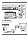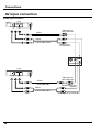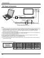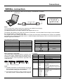
1
The model number and serial number are on the back
of your display. Record these numbers in the spaces below.
Refer to these numbers whenever you communicate
with your Toshiba dealer about this display.
50HP81
Model number:
Serial number:
TOSHIBA CORPORATION, 2001
WARNING
RISK OF ELECTRIC SHOCK
DO NOT OPEN
WARNING: To reduce the risk of electric shock do not remove cover or back. No
user-serviceable parts inside. Refer servicing to qualified service personnel.
The lightning flash with
arrow-head within a triangle
is intended to tell the user
that parts inside the product
are a risk of electric shock to
persons.
The exclamation point within
a triangle is intended to tell
the user that important
operating and servicing
instructions are in the papers
with the appliance.
WARNING: To prevent damage which may result in fire or shock hazard, do not expose this appliance to
rain or moisture.
WARNING: 1) To prevent electric shock, do not remove cover. No user serviceable parts inside. Refer servicing to
qualified service personnel.
2) Do not remove the grounding pin on the power plug. This apparatus is equipped with a three pin
grounding-type power plug. This plug will only fit a grounding-type power outlet. This is a safety
feature. If you are unable to insert the plug into the outlet, contact an electrician.
Do not defeat the purpose of the grounding plug.
2
Important Safety Instructions
1) Read these instructions.
All the safety and operating instructions should be read before the appliance is operated.
2) Keep these instructions.
The safety and operating instructions should be retained for future reference.
3) Heed all warnings.
All warnings on the appliance and in the operating instructions should be adhered to.
4) Follow all instructions.
All operating and use instructions should be followed.
5) Do not use this apparatus near water.
For example, near a bathtub, wash bowl, kitchen sink, or laundry tub, in a wet basement, or near a swimming pool, and
the like.
6) Clean only with a dry cloth.
Do not use liquid cleaners or aerosol cleaners. Use a dry cloth for cleaning.
7) Do not block any ventilation openings. Install in accordance with the manufacturer’s instructions.
Slots and openings in the cabinet are provided for ventilation and to ensure reliable operation of the product and to
protect it from overheating. The openings should never be blocked by placing the product on a bed, sofa, rug, or other
similar surface.
8) Do not install near any heat sources such as radiators, heat registers, stoves, or other apparatus (including amplifiers)
that produce heat.
This product should not be placed in a built-in installation such as a bookcase or rack unless proper ventilation is
provided or the manufacturer’s instructions have been adhered to.
9) Do not defeat the safety purpose of the polarized or grounding-type plug. A polarized plug has two blades with one wider
than the other. A grounding type plug has two blades and a third grounding prong. The wide blade or the third prong are
provided for your safety. If the provided plug does not fit into your outlet, consult an electrician for replacement of the
obsolete outlet.
10) Protect the power cord from being walked on or pinched particularly at plugs, convenience receptacles, and the point
where it exits the apparatus.
11) Only use attachments / accessories specified by the Manufacturer.
12) Use only with the cart, stand, tripod, bracket, or table specified by the manufacturer, or sold with the
apparatus. When a cart is used, use caution when moving the cart / apparatus combination to avoid
injury from tip-over.
Quick stops, excessive force, and uneven surfaces may cause the appliance and cart combination
to overturn.
13) Unplug this apparatus during lightning storms or when unused for long periods of time.
This will prevent damage to the product due to lightning and power-line surges.
14) Refer all servicing to qualified service personnel. Servicing is required when the apparatus has been damaged in any
way, such as power-supply cord or plug is damaged, liquid has been spilled or objects have fallen into the apparatus,
the apparatus has been exposed to rain or moisture, does not operate normally, or has been dropped.
3
Dear TOSHIBA Customer
Welcome to the TOSHIBA family of customers. We hope that you will have many years of enjoyment
from your new Wide Plasma Display.
To obtain maximum benefit from your set, please read these Instructions before making any adjustments,
and retain them for future reference.
Retain your purchase receipt also, and note the model number and serial number of your set in the
space provided on the front cover of these instructions.
Note:
Do not allow a still picture to be displayed for an extended period, as this can cause a permanent
ghost image to remain on the Wide Plasma Display.
Examples of still pictures include logos, video games, computer images, teletext and images
displayed in 4:3 mode.
Trademark Credits
VGA is a trademark of International Business Machines Corporation.
S-VGA is a registered trademark of the Video Electronics Standard Association.
Even if no special notation has been made of company or product trademarks, all trademarks have been fully
respected.
•
•
4
Table of Contents
Important Safety Instructions ....................................... 3
FCC STATEMENT ........................................................... 6
Safety Precautions ......................................................... 7
Accessories .................................................................... 9
Accessories Supplied .................................................... 9
Optional Accessories .................................................... 9
Remote Control Batteries ............................................ 10
Basic Controls .............................................................. 11
Connections ................................................................. 12
Speaker connection .................................................... 13
AV Input connection .................................................... 13
COMPONENT/RGB Input connection ........................ 15
PC Input connection .................................................... 16
SERIAL connection ..................................................... 17
Power ON/OFF and Input Signal Selection ................ 18
Power ON/OFF ........................................................... 18
Select the Input Signal ................................................ 19
On-Screen Menu Display from Remote Control ........ 20
Selecting the On-Screen Menu Language .................. 21
ASPECT Controls ......................................................... 22
Adjusting PICTURE POS./SIZE ................................... 24
SOUND Adjustment ..................................................... 26
MUTE .......................................................................... 26
SURROUND Controls .................................................. 27
PICTURE Adjustments ................................................. 28
ADVANCED SETTINGS .............................................. 29
SET UP for Input Signals ............................................. 30
COMPONENT/RGB IN SELECT ................................ 30
3D Y/C FILTER-For NTSC Video images ................... 30
COLOR SYSTEM / AUTO ........................................... 31
SYNC .......................................................................... 32
PULL IN RANGE ......................................................... 32
CLAMP POSITION ..................................................... 32
H-FREQ. (kHz)/V-FREQ. (Hz) .................................... 32
Troubleshooting ........................................................... 33
Specifications ............................................................... 34
Limited United States Warranty .................................. 36
LIMITED CANADIAN WARRANTY ............................... 37
5
FCC STATEMENT
FCC STATEMENT
This equipment has been tested and found to comply with the limits for a Class B digital device, pursuant to Part 15 of
the FCC Rules. These limits are designed to provide reasonable protection against harmful interference in a residential
installation. This equipment generates, uses and can radiate radio frequency energy and, if not installed and used in
accordance with the instructions, may cause harmful interference to radio communications. However, there is no
guarantee that interference will not occur in a particular installation. If this equipment does cause harmful interference
to radio or television reception, which can be determined by turning the equipment off and on, the user is encouraged
to try to correct the interference by one of the following measures:
• Reorient or relocate the receiving antenna.
• Increase the separation between the equipment and receiver.
• Connect the equipment into an outlet on a circuit different from that to which the receiver is connected.
• Consult the dealer or an experienced radio/TV technician for help.
This device complies with Part 15 of the FCC Rules. Operation is subject to the following two conditions: (1) This
device may not cause harmful interference, and (2) this device must accept any interference received, including
interference that may cause undesired operation.
FCC CAUTION:
To ensure continued compliance and to avoid possible undesirable interference, the provided ferrite cores must
be used when connecting this Wide Plasma Display to video equipment; and maintain at least 15.75˝ (40 cm) of
space from other peripheral devices. Refer to instructions on pages 13 and 16. Any changes or modifications not
expressly approved by Toshiba America Consumer Products, Inc. could cause harmful interference and may
void the user’s authority to operate this device.
FCC Declaration of Conformity
Responsible Party:
Toshiba America Consumer Products, Inc.
1420 Toshiba Drive, Lebanon, TN 37087
Contact Source:
Toshiba America Consumer Products, Inc.
1420 Toshiba Drive, Lebanon, TN 37087
CANADIAN NOTICE:
This Class B digital apparatus complies with Canadian ICES-003.
6
Safety Precautions
WARNING
Setup
Do not place the Wide Plasma Display on sloped or unstable surfaces.
The Wide Plasma Display may fall off or tip over.
•
Do not place any objects on top of the Wide Plasma Display.
If water spills onto the Wide Plasma Display or foreign objects get inside it, a short-circuit may occur which could
result in fire or electric shock. If any foreign objects get inside the Wide Plasma Display, please consult an
Authorized Service Center.
•
Do not cover the ventilation holes.
Doing so may cause the Wide Plasma Display to overheat, which can cause fire or damage to the Wide Plasma
Display.
•
If using the pedestal (optional accessory), leave a space of 3 15/16” (10 cm) or more at the top, left and right, 2 3/8”
(6 cm) or more at the bottom, and 2 3/4” (7 cm) or more at the rear. If using some other setting-up method, leave
a space of 3 15/16” (10 cm) or more at the top, bottom, left and right, and 3/4” (1.9 cm) or more at the rear.
AC Power Supply Cord
The Wide Plasma Display is designed to operate on 120 V AC, 50/60 Hz.
Securely insert the power cord plug as far as it will go.
If the plug is not fully inserted, heat may be generated which could cause fire. If the plug is damaged or the wall
socket plate is loose, they should not be used.
•
Do not handle the power cord plug with wet hands.
Doing so may cause electric shock.
•
Do not do anything that might damage the power cable. When disconnecting the power cable, hold the plug,
not the cable.
Do not make any modifications, place heavy objects on, place near hot objects, heat, bend, twist or forcefully pull
the power cable. Doing so may cause damage to the power cable which can cause fire or electric shock. If damage
to the cable is suspected, have it repaired at an Authorized Service Center.
•
If the Wide Plasma Display is not in use for a long period of time, unplug the power cord from the wall outlet.
If problems occur during use
If a problem occurs (such as no picture or no sound), or if smoke or an abnormal odor is detected from the
Wide Plasma Display, unplug the power cord immediately.
Continuous use of the Display under these conditions might cause fire or permanent damage to the unit. Have the
Display evaluated at an Authorized Service Center. Service to the Display by any unauthorized personnel is
strongly discouraged due to its high voltage and dangerous nature.
•
If water or foreign objects get inside the Wide Plasma Display, if the Wide Plasma Display is dropped, or if the
cabinet becomes damaged, disconnect the power cord plug immediately.
A short may occur, which could cause fire. Contact an Authorized Service Center for all repairs that need to be
made.
•
7
Safety Precautions
CAUTION
This Wide Plasma Display is for use only with the following optional accessories. Use with any other type of
optional accessories may cause instability which could result in the possibility of injury.
(All of the following accessories are manufactured by TOSHIBA Corporation)
................................................... PSS501
• Speakers....................................................
Pedestal
PTS501
•
..................
Wall-hanging
bracket
(vertical)
PWB501
•
..................
Wall-hanging
bracket
(angled)
PWB502
•
Always be sure to ask a qualified technician to install and set up accessories.
When using the Wide Plasma Display
Do not bring your hands, face or objects close to the ventilation holes of the Wide Plasma Display.
The top of the Wide Plasma Display is usually very hot due to the high temperature of exhaust air being released
through the ventilation holes. Burns or personal injuries can happen if any body parts are brought too close. Placing
any object near the top of the display could also result in heat damages to the object as well as to the Display if its
ventilation holes are blocked.
•
Be sure to disconnect all cables before moving the Wide Plasma Display.
Moving the Display with its cables attached might damage the cables which, in turn, can cause fire or electric
shock.
•
Disconnect the power plug from the wall outlet as a safety precaution before carrying out any cleaning.
Electric shock can result if this is not done.
•
Clean the power cable regularly to prevent it from becoming dusty.
Built-up dust on the power cord plug can increase humidity which might damage the insulation and cause fire.
Unplug the cord from the wall outlet and clean it with a dry cloth.
•
Cleaning and maintenance
The front of the display panel has been specially treated. Wipe the panel surface gently using only a dry, soft,
lint-free cloth.
Do not scratch or hit the surface of the panel with fingernails or other hard objects. Furthermore, avoid contact with
volatile substances such as insect sprays, solvents and thinner, otherwise the quality of the surface may be
adversely affected.
•
If the cabinet becomes dirty, wipe it with a soft, dry cloth.
If the cabinet is particularly dirty, soak the cloth in a weak detergent solution and then wring the cloth dry. Use this
cloth to wipe the cabinet, and then wipe it dry with a dry cloth.
Do not allow any detergent to come into direct contact with the surface of the Wide Plasma Display. If water
droplets get inside the unit, operating problems may result.
Avoid contact with volatile substances such as insect sprays, solvents and thinner, otherwise the quality of the
cabinet surface may be adversely affected or the coating may peel off. Furthermore, do not leave it for long periods
in contact with articles made from rubber or PVC.
•
•
•
Note:
Do not allow a still picture to be displayed for an extended period, as this can cause a permanent ghost image to
remain on the Wide Plasma Display.
Examples of still pictures include logos, video games, computer images, teletext and images displayed in 4:3 mode.
8
Accessories
Accessories Supplied
Check that you have the Accessories and items shown
Operating Instruction book
Remote Control Transmitter
EUR646527
Batteries for the Remote
Control Transmitter
(AA(R6) Battery × 2)
INPUT
SURROUND
VOL
N
R
PICTURE
SOUND
SET UP
PICTURE
POS. /SIZE
PC
ASPECT
OFF TIMER
PLASMA DISPLAY
RCA-BNC
adapter plug × 4
Speaker Wire × 2
Ferrite core
Note:
From the factory, these adapters have already been put on the rear input terminals.
Optional Accessories
• Speakers
• Pedestal
• Wall-hanging bracket (vertical)
• Wall-hanging bracket (angled)
PSS501
PWB501
PTS501
PWB502
For assembling
Full instructions are supplied with each optional accessories for use with this Wide Plasma Display.
9
Remote Control Batteries
Requires two AA batteries.
1. Turn the transmitter face down.
Press and slide off the battery
cover.
2. Install the batteries as shown in
the battery compartment.
(Polarity + or – must match the
markings in the compartment).
3. Replace the cover and slide it
back in until the lock snaps.
Two "AA" size
Helpful Hint:
For frequent remote control users, replace old batteries with
Alkaline batteries for longer life.
Precaution on battery use
Incorrect installation can cause battery leakage and corrosion that will damage the remote control transmitter.
Observe the following precautions:
1. Batteries should always be replaced as a pair. Always use new batteries when replacing the old set.
2. Do not combine a used battery with a new one.
3. Do not mix battery types (example: “Zinc Carbon” with “Alkaline”).
4. Do not attempt to charge, short-circuit, disassemble, heat or burn used batteries.
5. Battery replacement is necessary when the remote control acts sporadically or stops operating the Plasma Display.
10
Basic Controls
INPUT
R - STANDBY
G POWER ON
Main Power On/Off Switch
Power Indicator
The Power Indicator will light.
Power-OFF .... Indicator not illuminated (The unit
will still consume some power as long as the
power cord is still inserted into the wall outlet.)
Stand-by .... Red
Power-ON ..... Green
•
–
VOL
+
Input button
(VIDEO (S-VIDEO)/COMPONENT,
RGB/PC Mode Selection)
Push the “INPUT” button to select
VIDEO(S-VIDEO)/COMPONENT or
RGB/PC input signal modes sequentially.
Volume Adjustment
Push the Volume Up “+” or
Down “–” button to
increase or decrease the
sound volume level.
•
•
Stand-by (ON/OFF) button
The Wide Plasma Display must first be plugged into
the wall outlet and turned on at the Main Power On/
Off Switch on the Wide Plasma Display (see page 18).
Push this button to turn the Wide Plasma Display ON,
from STANDBY mode. Push it again to turn the Wide
Plasma Display OFF to STANDBY mode.
Status button
Push the “Status” button to display
the current system status.
VIDEO
NORMAL
SURROUND button
(see page 27)
Input button
(VIDEO(S-VIDEO)/COMPONENT,
RGB/PC Mode Selection)
Press to select VIDEO(S-VIDEO)/
COMPONENT or RGB/PC input signal
modes sequentially. (see page 19)
1
2
INPUT
SURROUND
OFF TIMER
90
Volume Adjustment
Press the Volume Up “+” or Down
“–” button to increase or decrease
the sound volume level.
3
1 VIDEO(S-VIDEO)/COMPONENT,
RGB/PC mode
2 Aspect mode (see page 22)
3 Off timer
The off timer indicator is displayed
only when the off timer has been set.
VOL
N
Sound mute On/Off (see page 26)
R
R button (see page 21, 24, 26, 30)
ACTION button
Press to make selections
N button
(see page 25, 26, 28, 29)
PICTURE
SOUND
SET UP
PICTURE button
(see page 28)
PICTURE
POS. /SIZE
POSITION buttons
SET UP button (see page 30)
SOUND button (see page 26)
ASPECT
PICTURE POS./SIZE button
(see page 24)
ASPECT button
Press to adjust the aspect ratio.
(see page 22)
PC
OFF TIMER
PC button
Push the “PC” mode selection
button to select the PC mode.
OFF TIMER button
This button is used to switch
The Wide Plasma Display may be preset to switch to stand-by after a fixed period.
directly to PC mode.
The setting changes to 30 minutes, 60 minutes, 90 minutes and 0 minutes (off
timer cancelled) each time the button is pressed.
30
60
90
0
When three minutes remain, “Off timer 3” will flash.
The off timer is canceled if a power interruption occurs.
11
Connections
SPEAKER
connectors (L)
SPEAKER
connectors (R)
– Cable fixing bands
Secure any excess cables with bands, as required.
To tighten:
To loosen:
Push
the knob
Pull
Pull
The TUNER connector is reserved
for future use
From monitor Out port on
Computer (see page 16)
L
L
AUDIO
S-VIDEO
AUDIO
VD
VIDEO
HD
PR/CR/R
PB/CB/B
Y/G
R
AV IN
AV IN connectors
(see page 13, 14)
12
From SERIAL port on Computer
(see page 17)
AUDIO
R
COMPONENT/RGB IN
PC IN
TUNER IN
COMPONENT/RGB IN and Audio IN connectors
(see page 15)
SERIAL
Connections
Speaker connection
When connecting the speakers, be sure to use only the optional accessory
speakers.
Refer to the speaker installation manual for details on speaker installation.
1
Make sure to use the supplied ferrite core
speaker cables to connect the speakers. Other
types of speaker cable are not suitable.
Remove the tubes from the
ends of the speaker cables.
2
Speakers (Optional accessories)
3
1
2
AV Input connection
Connect the signal source equipment (see pages 14 to 17).
(Example) When connecting an S-VIDEO VCR
(S-VIDEO VCR)
L
R
Audio
OUT
L
Video
OUT
S-Video
OUT
AUDIO
S-VIDEO
VIDEO
R
AV IN
S-VIDEO 4-pin connector
Luminance earth
Chrominance earth
Luminance in
Chrominance in
Video input to
S-VIDEO connector
S-VIDEO
AUDIO
2×RCA audio cables
Audio input to L/R connectors
13
Connections
AV Input connection
VIDEO signal connection
(VCR)
R
Audio
OUT L
Video
OUT
VIDEO
Video input to
BNC connector
RCA-BNC video cable
AUDIO
2×RCA audio cables
Audio input to
L/R connectors
L
AUDIO
VIDEO
S-VIDEO
R
AV IN
(VCR)
R
Audio
OUT L
Video
OUT
VIDEO
RCA video cable
AUDIO
Video input to
BNC connector
RCA-BNC adapter plug
(supplied)
2×RCA audio cables
Audio input to L/R connectors
14
Connections
COMPONENT/RGB Input connection
Component signals (Y, PB, PR) connection
DVD Player
L
AUDIO
VD
R
Audio
OUT L
HD
PB
PB/CB/B
Y/G
R
DVD (Y,PB, PR) OUT
Y
PR/CR/R
COMPONENT/RGB IN
PR
RCA-BNC adapter plug
(supplied)
Y, PB, PR
3×RCA
video cables
AUDIO
2×RCA audio cables
Audio input to L/R connectors
Notes:
(1) Change the “COMPONENT/RGB-IN” setting in the “SET UP” menu to “Y/PB/PR”. (see page 30, 32)
(2) Additional equipment and cables shown are not supplied with this set.
RGB signal (R, G, B, HD, VD) connection
Example of input signal source
RGB input to
R, G, B, HD, VD connectors
HDTV-compatible VCR
5×BNC
RGB cables
L
AUDIO
or
VD
HD
PR/CR/R
PB/CB/B
Y/G
R
COMPONENT/RGB IN
RGB camera
VD
HD
AUDIO
2×RCA audio cables
Audio input to
L/R connectors
Notes:
(1) Change the “COMPONENT/RGB-IN” setting in the “SET UP” menu to “RGB”. (see page 30, 32)
(2) Additional equipment and cables shown are not supplied with this set.
15
Connections
PC Input connection
COMPUTER
AUDIO
PC IN
POWER
/
R - STANDBY
INPUT
—
VOL
+
G POWER ON
Gender changer (if necessary)
D-sub 15p
RGB
PC cable
Ferrite core
(supplied)
Less than
7 7/8"
(20 cm)
Audio
1/8" (3mm) stereo plug
Connect a cable which matches
the audio output port on the computer.
Notes:
(1) Computer signals which can be input are those with a horizontal scanning frequency of 15.5 to 110 kHz and vertical
scanning frequency of 48 to 120 Hz. (However, signals exceeding 1200 lines may not be displayed properly.)
(2) The signal resolution is a maximum of 1024 × 768 dots when the aspect mode is set to “NORMAL”, and 1366 × 768
dots when the aspect mode is set to “FULL”. If the signal resolution exceeds these maximums, it may not be
possible to show fine detail with sufficient clarity.
(3) The PC input terminals are DDC1/2B-compatible. If the computer being connected is not DDC1/2B-compatible, you
will need to make setting changes to the computer at the time of connection.
(4) Some PC models cannot be connected to the set.
(5) There is no need to use an adapter for computers with an MS-DOS 5 (or greater) compatible D-sub 15P port.
(6) The computer shown in the illustration is for example purposes only.
(7) Additional equipment and cables shown are not supplied with this set.
(8) Do not set the horizontal and vertical scanning frequencies on the PC for PC signals which are above or below the
specified frequency range.
Signal Names for D-sub 15P Connector
11 12 13 14 15
6
7
1
9 10
8
2
3
4
5
Pin layout for PC input
terminal
16
Pin No.
1
2
3
4
5
Signal Name
R
G
B
GND (Ground)
GND (Ground)
Pin No.
Signal Name
Pin No.
6
GND (Ground)
11
7
GND (Ground)
12
8
GND (Ground)
13
9
NC (not connected)
14
10
GND (Ground)
15
Signal Name
GND (Ground)
SDA
HD/SYNC
VD/SYNC
SCL
Connections
SERIAL connection
The SERIAL port is used when the Wide Plasma Display is controlled by a computer.
COMPUTER
SERIAL
6
1
RS-232C cable
7
2
8
3
9
4
5
Pin layout for RS-232C
D-sub 9p
Notes:
(1) Use the RS-232C cable to connect the computer to the Wide Plasma Display.
(2) The computer shown is for example purposes only.
(3) Additional equipment and cables shown are not supplied with this set.
The SERIAL port conforms to the RS-232C interface specification, so that the Wide Plasma Display can be controlled
by a computer which is connected to this port.
The computer will require software which allows the sending and receiving of control data which satisfies the conditions
given below. Use a computer application such as a software programming language. Refer to the documentation for the
computer application for details.
Communication parameters
Signal level
Synchronization method
Baud rate
Parity
Character length
Stop bit
X parameter
S parameter
Basic format for control data
The transmission of control data from the computer starts
with a STX signal, followed by the command, the
parameters, and then an ETX signal in that order. If there
are no parameters, then the parameter signal does not
need to be sent.
STX
C1 C2 C3
Start
(02h)
:
RS-232C Pin assignment
Pin number
Signal
2
RXD
3
TXD
5
GND
4 • 6
NC
7
Shorted
8
1 • 9
NC
RS-232C compliant
Asynchronous
9600 bps
None
8 bits
1 bit
None
None
P1 P2 P3 P4 P5
ETX
Colon
Parameter(s)
(1 - 5 bytes)
3-character
command (3bytes)
End
(03h)
Note:
(1) If multiple commands are transmitted, be sure to wait
for the response for the first command to come from
this unit before sending the next command.
(2) If an incorrect command is sent by mistake, this unit
will send an “ER401” command back to the computer.
Command
Command
PON
POF
AUU
AUD
AMT
IIS
DAM
Parameter
None
None
None
None
None
None
VID
YP1
RG1
None
NORM
ZOOM
FULL
JUST
SELF
Control details
Power ON
Power OFF
Volume increase
Volume decrease
Mute (toggle)
Input select (toggle)
AV Mode
Component / RGB mode (processed as
Y/PB/PR or RGB signals as set by this unit)
PC mode
Screen mode select (toggle)
NORMAL (4:3)
ZOOM
FULL
JUST
AUTO
17
Power ON/OFF and Input Signal Selection
Power ON/OFF
Connecting the plug to the Wall Outlet
Push the POWER switch on the Wide Plasma Display to
turn the set on POWER-ON
Power Indicator: Green
Example: The screen below is displayed for a while after
the Wide Plasma Display is turned on. (setting
condition is an example.)
R - STANDBY
INPUT
–
VOL
When the POWER is turned on for the first time, the
LANGUAGE selection screen is displayed.
+
G POWER ON
From the second time on, language selection can be
done from the setup menu. (see page 21)
R - STANDBY
G POWER ON
Select the desired language using the
button.
press the store
Power Indicator
Remote Control Sensor
and
keys and
OSD LANGUAGE
English (UK)
Deutsch
Fran ais
Italiano
Espa ol
ENGLISH (US)
From the second time on, the screen shown below is
displayed (setting condition is an example).
VIDEO
NORMAL
INPUT
SURROUND
Press the
button on the remote control to turn the
Wide Plasma Display on
Power Indicator: Green
VOL
N
18
button on the remote control to turn the
Press the
Wide Plasma Display off
Power Indicator: Red (standby)
R
To turn the power for the Wide Plasma Display off, press
the
switch on the Wide Plasma Display, when the
Wide Plasma Display is on or in standby mode.
Power ON/OFF and Input Signal Selection
Select the Input Signal
INPUT
Press the INPUT button to select the input
video signal desired from equipment such as
a VCR which has been connected to the
Wide Plasma Display.
Input signals will change as follows:
For COMPONENT INPUT (see page 30)
R - STANDBY
INPUT
–
VOL
+
G POWER ON
VIDEO
INPUT
–
PC
For RGB INPUT (see page 30)
+
VOL
COMPONENT
VIDEO
RGB
PC
INPUT
SURROUND
VOL
N
R
19
On-Screen Menu Display from Remote Control
To PICTURE adjust menu
(see page 28)
PICTURE
NORMALIZE NORMAL
PICTURE MENU
PICTURE
BRIGHTNESS
COLOR
TINT
SHARPNESS
COLOR TEMP
ADVANCED SETTINGS
STANDARD
0
0
0
0
0
NORMAL
ON
INPUT
SURROUND
NORMALIZE
VOL
RETURN
ADJUST
SELECT
N
R
To ADVANCED SETTINGS
menu (see page 29)
ADVANCED SETTINGS
NORMALIZE NORMAL
BLACK EXTENSION
W/B HIGH R
W/B HIGH B
W/B LOW R
W/B LOW B
GAMMA
PICTURE
0
0
0
0
0
SOUND
SET UP
PICTURE
POS. /SIZE
ASPECT
2. 2
NORMALIZE
RETURN
ADJUST
SELECT
PC
OFF TIMER
PLASMA DISPLAY
To PICTURE POS./SIZE adjust
menu (see page 24)
PICTURE POS./SIZE
NORMALIZE
H-POS
H-SIZE
V-POS
V-SIZE
NORMAL
NORMALIZE
ADJUST
SELECT
20
RETURN
On-Screen Menu Display from Remote Control
To SOUND adjust menu (see page 26)
SOUND
NORMALIZE
AUDIO MENU
BASS
TREBLE
BALACE
SURROUND
To SIGNAL screen for VIDEO
(see page 31)
NORMAL
STANDARD
0
0
0
ON
[ VIDEO ]
SIGNAL
3D Y/C FILTER (NTSC)
COLOR SYSTEM
AUTO (4:3 )
NORMALIZE
ON
AUTO
NORMAL
RETURN
ADJUST
SELECT
To SIGNAL screen for
COMPONENT (see page 32)
[ COMPONENT ]
SIGNAL
CLAMP POSITION
1 Press to select “SIGNAL”
To SET UP menu (see page 30)
menu.
[ RGB ]
SIGNAL
SET UP
COMPONENT/RGB-IN SELECT
RGB
2 Press to access
SIGNAL
OSD LANGUAGE
To SIGNAL screen for RGB
(see page 32)
“SIGNAL” setup
menu.
ENGLISH (US)
RETURN
H&V
SYNC
NARROW
PULL-IN RANGE
CLAMP POSITION
H-FREQ. 31.5 kHz
V-FREQ. 60.0 Hz
R
SELECT
Press the R button to
return to “SET UP” menu.
Note:
“SIGNAL” setup menu displays different setting conditions for each input
signal. (see page 19)
To SIGNAL screen for PC
(see page 32)
[ PC ]
SIGNAL
H&V
SYNC
NARROW
PULL-IN RANGE
CLAMP POSITION
H-FREQ. 31.5 kHz
V-FREQ. 60.0 Hz
Selecting the On-Screen Menu Language
SET UP
Press to display the SET UP menu.
Press to select OSD LANGUAGE.
SET UP
COMPONENT/RGB-IN SELECT
RGB
Press to select your preferred language.
SIGNAL
Selectable
languages
OSD LANGUAGE
English (UK)
Deutsch
Français
Italiano
Español
ENGLISH (US)
ENGLISH (US)
RETURN
SELECT
..... (Japanese)
21
ASPECT Controls
The Wide Plasma Display will allow you to enjoy viewing the picture at its maximum size, including wide screen cinema
format picture.
ASPECT
INPUT
VOL
N
R
SOUND
SET UP
PICTURE
POS. /SIZE
PC
ASPECT
OFF TIMER
PLASMA DISPLAY
22
NORMAL
AUTO
SURROUND
PICTURE
ASPECT button
The aspect mode changes each time the ASPECT button
is pressed.
ZOOM
FULL
JUST
Notes:
(1) During RGB and PC input signal modes, the mode switches
between “NORMAL” and “FULL” only.
(2) For a 525p (480p) signal input using “COMPONENT” input signal
mode, the mode switches between “ZOOM” and “FULL” only.
(3) For a 1125i (1080i), 750p (720p) signal input using
“COMPONENT” input signal mode, the mode is set to “FULL”
mode, and switching is not possible.
For a 525i (480i), 625i (575i) signal input using “Component”
input signal mode, “Auto” cannot be selected.
(4) The aspect mode is stored separately for each input terminal
(VIDEO, COMPONENT, RGB and PC).
ASPECT Controls
Picture
Mode
Explanation
NORMAL mode will display a 4:3 picture at its standard
4:3 size.
4
NORMAL
NORMAL
3
4
ZOOM mode magnifies the central section of the picture.
16
ZOOM
ZOOM
3
4
9
FULL mode will display the picture at its maximum size
but with sight elongation.
16
FULL
FULL
3
4
9
16
JUST
JUST
3
4
9
16
AUTO
3
AUTO
For an elongated image
9
Image is expanded
4
3
For a 4:3 image
Changes in accordance
with the AUTO mode
setting (see page 31)
JUST mode (TheaterWide®) will display a 4:3 picture at
its maximum size but with aspect correction applied to
the center of the screen so that elongation is only
apparent at the left and right edges of the screen. The
size of the picture will depend on the original signal.
Auto mode will automatically enlarge the display
(depending on the picture source), allowing you to view
the picture at its maximum size.
Note:
AUTO mode is designed to automatically adjust the aspect
ratio to handle a mix of 16:9 and 4:3 program material.
Certain 4:3 program material, such as stock market data
screens, may occasionally cause the image size to change
unexpectedly. When viewing such programs, it is
recommended that the ASPECT be set to NORMAL.
Notes:
(1) Do not allow 4:3 mode to be displayed for an extended period, as this can cause a permanent ghost image to remain
on the Plasma Display Panel.
(2) The S-VIDEO terminal on this set can detect specially encoded signals that are compatible with a wide screen monitor.
When a full image from the S-VIDEO terminal of specially encoded video is detected by the set, the screen size is
automatically set to FULL mode.
23
Adjusting PICTURE POS./SIZE
Adjusting screen
1
ASPECT
Press to select the screen mode to
adjust (see page 23).
INPUT
2
SURROUND
PICTURE
POS. /SIZE
Press to display the PICTURE POS./
SIZE menu.
VOL
N
R
Press to select H-POS/H-SIZE/V-POS/
V-SIZE/CLOCK PHASE.
PICTURE
During “VIDEO” and
“COMPONENT” input signal modes.
During “RGB” and “PC”
input signal modes.
PICTURE POS./SIZE
PICTURE POS./SIZE
NORMALIZE
H-POS
H-SIZE
V-POS
V-SIZE
NORMALIZE NORMAL
H-POS
H-SIZE
V-POS
V-SIZE
CLOCK PHASE
NORMAL
NORMALIZE
ADJUST
SELECT
RETURN
SOUND
SET UP
PICTURE
POS. /SIZE
PC
ASPECT
OFF TIMER
NORMALIZE
ADJUST
RETURN
SELECT
PLASMA DISPLAY
3
Press to adjust screen/position
(see page 25).
R
Press to exit adjust mode.
Notes:
(1) Adjustment details are stored separately for different input signal formats (Adjustments for component signals are
stored for 525i (480i), 625i (575i), 525p (480p), 1125i (1080i) and 750p (720p) each, and RGB/PC signals are stored
for each frequency.)
(2) If a “Cue” or “Rew” signal from a VCR or DVD player is received, the picture position will shift up or down. This
picture position movement cannot be controlled by the PICTURE POS./SIZE function.
24
Adjusting PICTURE POS./SIZE
When the Position Left “ ” button is pressed
When the Position Right “ ” button is pressed
When the Position Left “ ” button is pressed
When the Position Right “ ” button is pressed
When the Position Left “ ” button is pressed
When the Position Right “ ” button is pressed
When the Position Left “ ” button is pressed
When the Position Right “ ” button is pressed
H-POS
H-SIZE
V-POS
V-SIZE
CLOCK PHASE
Flickering and distortion can be eliminated by using the Position Left “ ” or Right “ ” button to
(RGB/PC in Mode) carry out adjustment.
Helpful Hint (
N
/
NORMALIZE
Normalization)
While the PICTURE POS./SIZE display is active, if either the N button on the remote control is pressed at any time or
the
(ACTION button) is pressed during “NORMALIZE”, then all adjustment values are returned to the factory
settings.
25
SOUND Adjustment
1
Press the SOUND
2
Select to adjust each item.
button to display the SOUND menu.
INPUT
Press to select the desired adjustment menu.
SURROUND
VOL
Select the desired level by listening to the sound.
N
PICTURE
R
SOUND
SET UP
PICTURE
POS S
BASS
Adjusts low sounds
SOUND
NORMALIZE
AUDIO MENU
BASS
TREBLE
BALACE
SURROUND
TREBLE
Adjusts high sounds
BALANCE
Adjusts left and right
volumes
NORMAL
STANDARD
0
0
0
ON
NORMALIZE
ADJUST
RETURN
STANDARD
Emits the original sound.
AUTO
SELECT
Automatically controls
proper volume level.
SURROUND (see next page)
• To end adjustments
R
Press R button
Note:
Press the SURROUND button to directly turn the surround effect ON and OFF. (see page 27)
Helpful Hint (
N
/
NORMALIZE
Normalization)
While the “SOUND” menu is displayed, if either the N button on the remote control is pressed at any time or the
(ACTION button) is pressed during “NORMALIZE”, then all adjustment values are returned to the factory settings.
Mute
Useful when answering the phone or receiving unexpected visitors.
Press this button to mute the sound.
Press again to reactivate sound. Sound is also reactivated when power is turned off or
volume level is changed.
26
SURROUND Controls
SURROUND
INPUT
SURROUND Button
The benefits of surround sound are enormous. You can be
completely enveloped in sound; just as if you were at a concert
hall or cinema.
The surround setting switches on and off each time the
SURROUND button is pressed.
ON
SURROUND
OFF
VOL
N
R
PICTURE
SOUND
SET UP
SURROUND
PICTURE
POS. /SIZE
PC
ASPECT
ON
Note:
The surround settings are stored separately for each SOUND mode
(AUTO, STANDARD).
OFF TIMER
PLASMA DISPLAY
27
PICTURE Adjustments
1
2
PICTURE
PICTURE
Press the PICTURE button on the
Remote Control to display the
PICTURE menu.
NORMALIZE NORMAL
PICTURE MENU
PICTURE
BRIGHTNESS
COLOR
TINT
SHARPNESS
COLOR TEMP
ADVANCED SETTINGS
Select to adjust each item.
Press to select the menu to adjust.
STANDARD
0
0
0
0
0
NORMAL
ON
NORMALIZE
ADJUST
Select the desired level by looking at the picture
behind the menu.
Press the left
modes.
PICTURE
NORMALIZE NORMAL
PICTURE MENU
PICTURE
BRIGHTNESS
COLOR
TINT
SHARPNESS
COLOR TEMP
ADVANCED SETTINGS
DYNAMIC
CINEMA
STANDARD
STANDARD
For viewing in standard (evening
lighting) environments.
This menu selects the normal levels of
BRIGHTNESS and PICTURE.
DYNAMIC
DYNAMIC
For viewing in brighter environments.
This menu selects higher than normal
levels of BRIGHTNESS and PICTURE.
RETURN
SELECT
Press the left or right button to
select “ON”. Press the down button
to enter ADVANCED SETTINGS mode.
ADVANCED SETTINGS ON
Enables fine picture adjustment at a
professional level (see page 29).
ADVANCED SETTINGS
NORMALIZE NORMAL
BLACK EXTENSION
W/B HIGH R
W/B HIGH B
W/B LOW R
W/B LOW B
GAMMA
button to switch between
STANDARD
STANDARD
0
0
0
0
0
NORMAL
ON
NORMALIZE
ADJUST
or right
RETURN
SELECT
CINEMA
CINEMA
Ideal for movies.
Can be selected for VIDEO/
COMPONENT.
•
Note:
If you would like to change the picture and color of the
selected PICTURE menu, adjust using the items in the
PICTURE menu. (see page 29)
0
0
0
0
0
2. 2
ADVANCED SETTINGS OFF
Displays images with settings of the
PICTURE menu.
Helpful Hint (
N
/
NORMALIZE
Press the left or right button to switch between
modes.
NORMAL
COOL
WARM
Normalization)
While the “PICTURE” menu is displayed, if either the N button on the remote control is pressed at any time or the
(ACTION button) is pressed during “NORMALIZE”, then all adjustment values are returned to the factory settings.
28
PICTURE Adjustments
Item
Effect
Adjustments
PICTURE
Less
More
BRIGHTNESS
Darker
Brighter
Adjusts for easier viewing of dark pictures
such as night scenes and black hair.
Adjusts slightly to a lighter color.
COLOR
Less
TINT
(NTSC only)
Selects the proper brightness and
density for the room.
More
Adjusts skin color.
Reddish
Greenish
Displays a sharp image.
SHARPNESS
Less
More
Notes:
(1) “COLOR” , “TINT” and “SHARPNESS”
settings cannot be adjusted for “RGB”
and “PC” input signal modes.
(2) You can change the level of each
function (CONTRAST, BRIGHTNESS,
COLOR, TINT, SHARPNESS) for
each PICTURE menu.
(3) The setting details for normal,
dynamic and cinema are stored
separately for each input mode
(VIDEO, COMPONENT, RGB and
PC).
(4) The “TINT” setting can be adjusted for
NTSC signal only.
Note:
There is little change when PICTURE is increased with a bright picture or reduced with a dark picture.
ADVANCED SETTINGS
Item
BLACK
EXTENSION
Details
Effect
Adjusts the dark shades of the image in gradation.
Less
More
Less
More
Less
More
Less
More
Less
More
Down
Up
W/B HIGH R
Adjusts the white balance for light red areas.
W/B HIGH B
Adjusts the white balance for light blue areas.
W/B LOW R
Adjusts the white balance for dark red areas.
W/B LOW B
Adjusts the white balance for dark blue areas.
GAMMA
2.0
2.2
2.5
Notes:
(1) Carry out “W/B” adjustment as follows.
A Adjust the white balance of the bright sections using the “W/B HIGH R” and “W/B HIGH B” settings.
B Adjust the white balance of the dark sections using the “W/B LOW R” and “W/B LOW B” settings.
C Repeat steps A and B to adjust.
Steps A and B affect each other’s settings, so repeat each step in turn to make the adjustment.
(2) The adjustment values are stored separately for each input mode (VIDEO, COMPONENT, RGB and PC).
(3) The adjustment range values should be used as an adjustment reference.
Helpful Hint (
N
/
NORMALIZE
Normalization)
While the “ADVANCED SETTINGS” menu is displayed, if either the N button on the remote control is pressed at any
time or the
(ACTION button) is pressed during “NORMALIZE”, then all adjustment values are returned to the factory
settings.
29
SET UP for Input Signals
COMPONENT/RGB IN SELECT
Select to match the signals from the source connected to the COMPONENT/RGB input terminals.
Y, PB, PR signals
“COMPONENT”
R, G, B, HD, VD signals
“RGB”
1
SET UP
Press to display the SET UP menu screen.
INPUT
Press to select the “COMPONENT/RGB IN
SELECT”.
2
SURROUND
Press to select the desired mode.
VOL
N
SET UP
R
COMPONENT/RGB-IN SELECT
RGB
SIGNAL
ENGLISH (US)
OSD LANGUAGE
RETURN
PICTURE
SOUND
SELECT
SET UP
COMPONENT
PICTURE
POS. /SIZE
RGB
ASPECT
R
Press to exit from adjust mode.
3D Y/C FILTER – For NTSC Video images
Select the SIGNAL from the “SET UP” menu during VIDEO (S-VIDEO) input signal
mode. (“SIGNAL [VIDEO]” menu is displayed.)
SET UP
COMPONENT/RGB-IN SELECT
RGB
Press to select the “3D Y/C FILTER (NTSC)”
SIGNAL
OSD LANGUAGE
Press to set ON/OFF.
ENGLISH (US)
RETURN
SELECT
Press
[ VIDEO ]
SIGNAL
R
Press to exit from adjust mode.
3D Y/C FILTER (NTSC)
COLOR SYSTEM
AUTO (4:3 )
CHANGE
SELECT
Note:
When on, this setting only affects NTSC input signals.
30
(store) button
ON
AUTO
NORMAL
RETURN
SET UP for Input Signals
COLOR SYSTEM / AUTO
Select SIGNAL from the “SET UP” menu during VIDEO (S-VIDEO) input
signal mode. (“SIGNAL [VIDEO]” menu is displayed.)
SET UP
COMPONENT/RGB-IN SELECT
RGB
Press to select the “COLOR SYSTEM” or “AUTO”.
SIGNAL
OSD LANGUAGE
Press to select each function.
ENGLISH (US)
RETURN
SELECT
Press
If the picture image becomes unstable:
With the system set on Auto, under conditions of
low level or noisy input signals the image may in
rare cases become unstable. Should this occur,
set the system to match the format of the input
signal.
Mode
Color system
[ VIDEO ]
SIGNAL
3D Y/C FILTER (NTSC)
COLOR SYSTEM
AUTO (4:3 )
CHANGE
ON
AUTO
NORMAL
RETURN
SELECT
Function
Set the color system to match the input signal. If set to “AUTO”, the color system
is determined automatically.
AUTO
AUTO (4:3)
(store) button
PAL
SECAM
M NTSC
NTSC
Set to “NORMAL” to view 4:3 images in an unchanged format when
AUTO is selected. If you would like to view 4:3 images in “Just” format, set
to “JUST”.
31
SET UP for Input Signals
Select SIGNAL from the “SET UP” menu during RGB or PC input signal mode.
Press to select each item.
[ COMPONENT ]
SIGNAL
CLAMP POSITION
Press to adjust.
The following operation methods are the same for both the SIGNAL [RGB]
and SIGNAL [PC].
[ RGB ]
SIGNAL
H&V
SYNC
NARROW
PULL-IN RANGE
CLAMP POSITION
H-FREQ. 31.5 kHz
V-FREQ. 60.0 Hz
[ PC ]
SIGNAL
H&V
SYNC
NARROW
PULL-IN RANGE
CLAMP POSITION
H-FREQ. 31.5 kHz
V-FREQ. 60.0 Hz
SYNC
Setting RGB sync signal setting:
Confirm that the input is set to RGB INPUT (this setting is valid only for RGB INPUT).
H&V:
The H and V sync signals are input from the HD/VD (BNC) connector.
ON G:
Uses a synchronized signal on the Video G signal, which is input
from the G (BNC) connector.
ON VIDEO: Compatible with the scart plug (Europe)
The composite video signal input from the VIDEO input terminal is
used by dividing the sync signals.
SYNC
H&V
SYNC
ON G
SYNC
ON VIDEO
Setting PC sync signal setting:
Confirm that the input is set to PC INPUT (this setting is valid only for PC INPUT).
H&V: The H and V sync signals are input from the HD/VD (BNC) connector.
ON G: Uses a synchronized signal on the Video G signal, which is input from the G (BNC) connector.
PULL IN RANGE
Sets the width for different frequencies.
PULL IN RANGE
NARROW
PULL IN RANGE
WIDE
(This setting is the same for both SIGNAL [RGB] and SIGNAL [PC].)
CLAMP POSITION
Adjusts the clamp position.
CLAMP POSITION
The following operation methods are the same for “SIGNAL” menu during
COMPONENT, RGB and PC input signal mode.
Normally, these adjustments are set to appropriate levels and, therefore, do not
need to be altered.
H-FREQ (kHz)/V-FREQ (Hz)
Displays the H (Horizontal)/V (Vertical) frequencies.
This display is valid only for RGB input and PC input.
Display range:
Horizontal 15.5 - 110 kHz
Vertical 48 - 120 Hz
32
H-FREQ.
V-FREQ.
31.5 kHz
60.0 Hz
Troubleshooting
Before you call for service, determine the symptoms and make a few simple checks as shown below.
Symptoms
Picture
Checks
Sound
Electrical Appliances
Cars/Motorcycles
Fluorescent light
Interference
Noisy Sound
Volume
(Check whether the mute function has been
activated on the remote control.)
Normal Picture
No Picture
No Sound
No Sound
Not plugged into AC outlet.
Not switched on.
Check PICTURE and BRIGHTNESS/ Volume
setting by pushing the power switch or standby button on the remote control.
If a signal with a non-applicable color system
format, or frequency is input, only the input
terminal indication is displayed.
No Picture
Normal Sound
Color controls set at minimum level.
Color system (see page 28, 29)
No Color
Normal Sound
Plasma Display panel
Symptoms
Some parts of the screen do
not light up
Check
The plasma display panel is manufactured using an extremely high level of
precision technology, however, sometimes some parts of the screen may be
missing picture elements or have luminous spots. This is not a malfunction.
Do not allow a still picture to be displayed for an extended period, as this can
cause a permanent ghost image to remain on the Wide Plasma Display.
Examples of still pictures include logos, video games, computer images, teletext
and images displayed in 4:3 mode.
Ghost images appear
Whirring sounds can be heard
from the display unit.
Note:
The permanent ghost image on the Plasma Display resulting from fixed image use
is not an operating defect and as such is not covered by the Warranty.
This product is not designed to display fixed images for extended periods of time.
The display unit is fitted with a cooling fan to dissipate heat generated during normal use.
The whirring sound is caused by rotation of the fan and is not a malfunction.
33
Specifications
50HP81
Power Source
Power Consumption
120 V AC, 50/60 Hz
Normal use
Stand-by condition
Power off condition
Plasma Display panel
Contrast Ratio
Brightness Capability
Screen size
Max. Amps 5.5 A
2.4 W
0.7 W
Drive method AC type
50-inch, 16:9 aspect ratio
3000:1
(Panel only) 500 cd / m2
(As a set) 300 cd / m2
1106 mm (W) × 622 mm (H) × 1269 mm (diagonal)
No. of pixels
1,049,088 (1366 (W) × 768 (H)) [4,098 × 768 dots]
Operating condition
34°F - 104°F (0°C - 40°C)
20% - 80%
Temperature
Humidity
Applicable signals
Color System
Scanning format
PC signals
NTSC, PAL, PAL60, SECAM, Modified NTSC
525i (480i), 625i (575i), 525p (480p), 750p (720p), 1125i(1080i)
XGA display
VGA, SVGA
SXGA, UXGA (compressed)
Horizontal scanning frequency 15.5 - 110 kHz
Vertical scanning frequency 48 - 120 Hz
Connection terminals
AV
COMPONENT/RGB
PC
SERIAL
SPEAKERS (6 Ω)
34
Video IN (BNC)
S-VIDEO IN (MINI DIN 4PIN)
AUDIO IN (RCA PIN JACK × 2)
Y/G (BNC)
1.0 Vp-p (75-ohm)
Y: 1 Vp-p (75-ohm), C: 0.286 Vp-p (75-ohm)
0.5 Vrms (high impedance)
1.0 Vp-p/composite (75-ohm)
0.7 Vp-p/non-composite (75-ohm)
PB/B (BNC)
0.7 Vp-p (75-ohm)
PR/R (BNC)
0.7 Vp-p (75-ohm)
HD (BNC)
1.0 - 5.0 Vp-p (high impedance)
VD (BNC)
1.0 - 5.0 Vp-p (high impedance)
AUDIO IN (RCA PIN JACK × 2)
0.5 Vrms (high impedance)
(HIGH-DENSITY D-SUB 15PIN)
R,G,B/0.7 Vp-p (75-ohm)
HD, VD/1.0 - 5.0 Vp-p (high impedance)
AUDIO IN (M3.5 JACK)
0.5 Vrms (high impedance)
EXTERNAL CONTROL TERMINAL (D-SUB9PIN) RS-232C COMPATIBLE
16W [8 W + 8 W] (10% THD)
For PSS501 only
Specifications
50HP81
Accessories Supplied
Remote Control Transmitter
Batteries
RCA-BNC adapter plug
Ferrite core
Speaker Wire
EUR646527
2 × AA Size
4p
1p
1 sets
Optional Supplied
Speakers
Pedestal
Wall-hanging bracket
(vertical)
PSS501
PTS501
PWB501
Wall-hanging bracket
(angled)
PWB502
Dimensions
(W × D × H)
47.6” (1210 mm) × 28.5” (724 mm) × 3.9” (98mm)
3.9"
(98 mm)
28.5" (724 mm)
47.6" (1210 mm)
POWER
/
R - STANDBY
INPUT
–
VOL
+
G POWER ON
Weight (Mass)
approx. 99.2 lbs (main unit only)
approx. 109.3 lbs (with speakers)
Note:
Design and specifications are subject to change without notice. Weight and dimensions shown are approximate.
35
– IMPORTANT –
Limited United States Warranty
Products purchased in the U.S.A. and used in Canada are not covered by these warranties.
Products Purchased in Canada and used in the U.S.A. are not covered by these warranties.
Toshiba America Consumer Products, Inc. (“TACP”) and Toshiba Hawaii Inc. (“THI”) make the following limited warranties. These limited warranties extend to the original
consumer purchaser or any person receiving this set as a gift from the original consumer purchaser and to no other purchaser or transferee.
Limited One (1) Year Warranty
Owner’s Manual and Demographic Card
TACP and THI warrant this product and its parts against defects in materials or
workmanship for a period of one (1) year after the date of original retail purchase.
During this period, TACP and THI will repair or replace a defective part, at their
option, with a new or refurbished part, without charge to you. TACP/THI Authorized
Service Station personnel will come to your home when warranty service is required.
Depending on the type of repair required, the service will either be performed in
your home or the set will be taken to the TACP/THI Authorized Service Station for
repair and returned to your home at no cost to you.
You should read this owner’s manual thoroughly before operating this product.
You should complete and mail the enclosed Demographic card within ten days
after you, or the person who has given you this product as a gift, purchased this
product. This is one way to enable TACP/THI to provide you with better customer
service and improved products. Failure to return the Demographic card will not
affect your rights under this warranty.
Where in-home service is not available via Toshiba’s Authorized Service network,
Toshiba will fulfill its obligation for warranty service via other appropriate means to
be determined by Toshiba including, but not limited to, exchange, refund or shipping
to and from an Authorized Service Center for repair.
The above warranties are subject to the following conditions;
Rental Units
The warranty for rental units begins with the first rental or thirty (30) days from the
date of shipment to the rental firm, whichever comes first.
Commercial Units
Products sold and used for commercial use have a limited ninety (90) day warranty
for all parts and labor.
Your Responsibility
(1) You must retain your bill of sale or provide other proof of purchase.
(2) All warranty servicing of this product must be made by an Authorized TACP/
THI Service Station.
(3) These warranties are effective only if the product is purchased and operated in
the U.S.A. or Puerto Rico.
(4) Labor service charges for set installation, set up, adjustment of customer controls
and installation or repair of antenna systems are not covered by this warranty.
Reception problems caused by inadequate antenna systems are your
responsibility.
(5) Warranties extend only to defects in materials or workmanship as limited above
and do not extend to any product or parts which have been lost or discarded by
you or to damage to products or parts caused by misuse, accident, damage caused
by Acts of God, such as lightning or fluctuations in electric power, improper
installation, improper maintenance or use in violation of instructions furnished
by us; or to units which have been modified or had the serial number removed,
altered, defaced or rendered illegible.
How to Obtain Warranty Service
If after following all of the operating instructions in this manual and checking the
section “BEFORE CALLING SERVICE PERSONNEL”, you find that service is
needed;
(1) Call the TACP toll free number 1-800-631-3811 after you find a defective
product or part to find the nearest TOSHIBA Authorized Service Station.
(2) Please present your bill of sale or other proof to the Authorized Service
Station. “TACP/THI Authorized Service Station personnel will come to your
home when warranty service is required. Depending on the type of repair
required, the service will either be performed in your home or the set will be
taken to the TACP/THI Authorized Service Station for repair and returned to
your home at no cost to you.”
For additional information,
visit our web site:
www.toshiba.com/tacp
In Hawaii contact:
Toshiba Hawaii, Inc. 327 Kamakee Street. Honolulu,
Hawaii 96814 (808) 591 -9281
All warranties implied by state law, including the implied warranties of merchantability and fitness for a particular purpose, are expressly limited to the duration of the
limited warranties set forth above. With the exception of any warranties implied by state law as hereby limited, the foregoing warranty is exclusive and in lieu of all other
warranties, guarantees, agreements and similar obligations of manufacturer or seller with respect to the repair or replacement of any parts. In no event shall TACP or THI
be liable for consequential or incidental damages.
No person, agent, distributor, dealer or company is authorized to change, modify or extend the terms of these warranties in any manner whatsoever. The time within which
action must be commenced to enforce any obligation of TACP or THI arising under this warranty or under any state, or law of the United States or any state thereof, is hereby
limited to 90 days from the date you discover or should have discovered, the defect. This limitation does not apply to implied warranties arising under state law.
This warranty gives you specific legal rights and you may also have other rights which may vary from state to state. Some states do not allow limitation on how long an
implied warranty lasts, when an action may be brought, or the exclusion or limitation of incidental or consequential damages, so the above provisions may not apply to you.
36
– IMPORTANT –
LIMITED CANADIAN WARRANTY
Products purchased in Canada and used in the U.S.A. are not covered by these warranties.
Products purchased in the U.S.A.and used in Canada are not covered by these warranties.
CANADIAN EXTENDED WARRANTY
To obtain a “CANADIAN EXTENDED WARRANTY” the
consumer must complete and forward the attached “CANADIAN
EXTENDED WARRANTY REGISTRATION FORM” to
TOSHIBA of CANADA LIMITED, CONSUMER ELECTRONICS
GROUP, WARRANTY REGISTRATION OFFICE, 191 McNABB
STREET, MARKHAM, ON L3R 8H2, (envelope enclosed) within
30 days of purchase!
This warranty offer provides an extension of the manufacturer’s
parts and labour warranty provided that the consumer registers for
a CANADIAN EXTENDED WARRANTY.
To obtain service under warranty, contact the nearest authorized
TOSHIBA SERVICE CENTRE or the nearest TOSHIBA FACTORY
SERVICE DEPARTMENT (list enclosed).
PRODUCTS UTILIZED FOR RENTAL OR COMMERCIAL
PURPOSES ARE NOT COVERED BY THIS WARRANTY.
This warranty applies only to the original purchaser and is not
transferable. This warranty does not apply to sets subjected to misuse,
neglect, accident, act of God or improper installation.
Sets with serial number removed, altered, replaced or defaced will not be
covered by this warranty. ALL IN-WARRANTY REPAIRS MUST
BE MADE BY A TOSHIBA FACTORY SERVICE DEPARTMENT,
OR BY AN AUTHORIZED TOSHIBA SERVICE CENTRE.
REPAIRS MADE ELSEWHERE WILL INVALIDATE THIS
WARRANTY.
THIS WARRANTY IS ONLY VALID WHEN THE SET IS
PURCHASED FROM AN AUTHORIZED TOSHIBA DEALER
AND USED IN CANADA.
THIS WARRANTY IS IN LIEU OF ALL OTHER WARRANTIES,
GUARANTIES OR AGREEMENTS, WHETHER EXPRESSED OR
IMPLIED, AND NO PERSON, AGENT, DISTRIBUTOR,
DEALER, SERVICE CENTRE OR COMPANY IS AUTHORIZED
TO CHANGE, MODIFY OR EXTEND ITS TERMS IN ANY
MANNER WHATSOEVER.
IMPORTANT: Also keep your “Bill of Sale” as proof of purchase.
WARRANTY:
TYPE OF SET:
PARTS:
LABOUR:
REMOTE CONTROL:
IN-HOME SERVICE
PDP
12 MONTHS
12 MONTHS
12 MONTHS
Thank you for purchasing this fine product from one of our authorized:
CANADIAN TOSHIBA DEALERS
(Detach)
CANADIAN EXTENDED WARRANTY REGISTRATION FORM
Please complete and mail this card immediately.
MODEL NO.
SERIAL NO.
DATE PURCHASED
INVOICE NO.
YOUR NAME
ADDRESS
CITY
PROVINCE
POSTAL CODE
DEALER NAME
CITY
PROVINCE
37
SERVICE DIVISION/82 TOTOWA ROAD, WAYNE, NEW JERSEY 07470
NATIONAL SERVICE DIVISION:1420B TOSHIBA DRIVE, LEBANON, TN. 37087
“www.toshiba.com/tacp”
SERVICE DIVISION/327 KAMAKEE STREET, HONOLULU, HAWAII 96814, U.S.A. TEL: (808) 591-9281
HEAD OFFICE/191 McNABB STREET MARKHAM, ONTARIO L3R 8H2, CANADA TEL: (905) 470-5400
SERVICE CENTERS/TORONTO: 191 McNABB STREET MARKHAM, ONTARIO L3R 8H2, CANADA TEL: (905) 470-5400
5
MONTREAL: 1643 NORTH SERVICE RD.,TRANS-CANADA HIGHWAY, DORVAL QUEBEC, H9P 1J1, CANADA
5
TEL: (514) 856-4100
5
VANCOUVER: 22171 FRASERWOOD WAY, RICHMOND, B.C. V6W 1J5, CANADA TEL: (604) 303-2500
ColorStream and TheaterWide are registered trademarks of Toshiba America Consumer Products, Inc.
PRINTED IN JAPAN
(01-06)