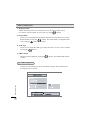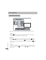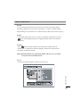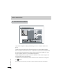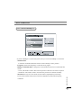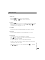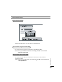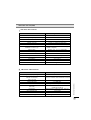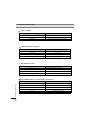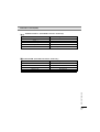
1
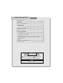
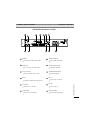
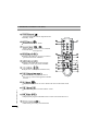
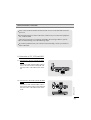
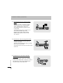
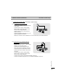
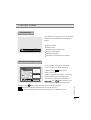
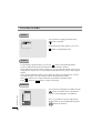
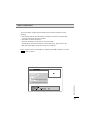
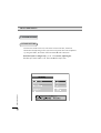
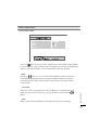
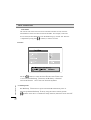
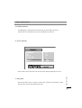
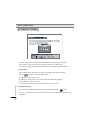
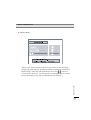
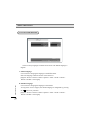
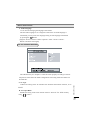
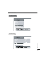
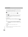
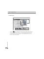
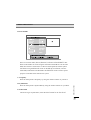
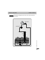
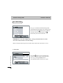
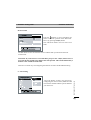
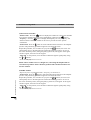
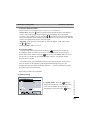
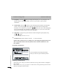
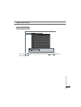
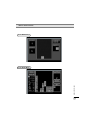
TOPFIELD
The User’s Manual
FREE TO AIR
Digital Satellite Receiver
TF3100FEi
TF3100FEP pro
- Embedded Positioner
Please read this User s Manual carefully.
The menu structure and specification can be changed without notice.
TABLE OF CONTENTS
INTRODUCTION
CONTENTS
FEATURES
FRONT/ REAR PANELS
1) FRONT PANEL
2) REAR PANEL
4
5
5
6
6
6
REMOTE CONTROL UNIT (RCU)
GETTING STARTED
FUNCTION GUIDE
MENU OPERATIONS
1) SYSTEM SETTING
2) ORGANIZING CHANNEL
3) ORGANIZING FAVORITES
4) INSTALLATION
* POSITIONER SETTING GUIDE(Positioner model only)
5) INFORMATION
6) GAME
TROUBLE SHOOTING (Q & A)
SPECIFICATIONS
8
14
15
17
18
28
30
31
38
50
52
54
55
CAUTION
RISK ELECTRIC SHOCK
Do NOT OPEN
This symbol indicates “dangerous voltage”
inside the product that presents a risk of
electric shock or personal injury.
This symbol indicates
important instructions
accompanying the product.
CAUTION: TO REDUCE THE RISK OF FIRE OR ELECTRIC SHOCK,
DO NOT EXPOSE THIS APPLIANCE TO RAIN OR MOISTURE
Please do not insert metal or alien substance into the slots
for the Modules and Cards.
In doing so can cause damage to the STB and reduce its life span.
WARNING Warning WARNING Warning WARNING
Please read the following recommended safety precautions carefully for your safety.
MAINS SUPPLY :
90-250V AC 50/60 Hz.
OVERLOADING :
Do not overload wall outlets, extension cords or adapters
as these can result in fire or electrical shock.
LIQUIDS :
Keep liquids away from the STB.
The apparatus shall not be exposed to dripping or splashing and
that no objects filled with liquids, such as vases, shall be placed
on the apparatus.
SMALL OBJECTS : Coins or other small objects must be kept away from the IRD
as they can fall through the ventilation slots of the IRD and
cause serious damage.
CLEANING :
Disconnect the IRD from the wall socket before cleaning it.
Use a dry cloth lightly dampened(no solvents) to clean
the exterior of the IRD.
VENTILATION :
Do not block the decoder’s ventilation slots.
Ensure that a free airflow is maintained around the IRD.
NEVER stand the IRD on soft furnishings or carpets.
Do not use or store the IRD where it is exposed to direct
sunlight or near a heater. NEVER stack other electronic
equipment on top of the IRD.
ATTACHMENTS : Do not use any attachments that are not recommended as these
may cause hazards or damage the equipment .
SERVICING :
Do not attempt to service this product yourself.
Refer all serving to qualified service agents.
LIGHTNING :
It is recommended that the IRD should remain connected at all
times to the mains supply and satellite dish (except when
working on the LNB). However, the manufacturer’s
instructions for safeguarding other equipment connected to the
IRD, i, e, TV set, must be followed during lightning storms.
LNB and the modem telephone line are essential.
EARTHING :
The LNB cable must be earthed to the system earth for
the satellite dish.
LOCATION :
Locate the IRD indoor place properly to prevent lightening,
raining and direct sunlight.
WARNI NG
CONNECTION TO THE SATELLITE DISH LNB :
Disconnect the IRD from the mains before connecting or
disconnecting the cable from the satellite dish.
FAILURE TO DO SO CAN DAMAGE THE LNB,
INTRODUCTION
Thank you for purchasing the Digital Satellite Receiver (STB).
This Digital Satellite Receiver is fully compliant with the international DVB
standard and thus transmits digital images, sounds, information guides and teletext
directly to your TV through the satellite. Now you can comfortably see and receive
digitally transmitted music, news, movie and sports satellite broadcasts in your office
or at your home.
In the Channel Search section, both the automatic channel search method and the
manual Search mode are provided. Also it supports DiSEqC 1.2, enabling you to move your
antenna in order to focus your preferred satellite. You can save up to 3500 TV and 1500
Radio channels and work around with the Favorite, Lock, Delete, Move and Sort
functions. The Menu is very modern and supports different languages.
All functions can be carried out using the remote control and some of the functions can
also be carried out using the front panel.
The STB is easy to use and adaptable for future advances. Please be aware that new
software may change the functions of the STB.
If you have any difficulties concerning the operation of your STB, please refer to the
relevant section of this manual, including the ‘Troubleshooting’. This Manual will
I NTRODUCTI ON
provide you with useful information on using the STB.
CONTENTS
Please ensure that the following items are included with the STB.
1) Remote control unit
2) Batteries (size AAA)
3) User’s Guide (this document)
FEATURES
Fully Compliant to DVB
Antenna/LNB control
- 22KHz mode On/Off
- 0/12V mode selection
- Automatic FEC Detection
- DiSEqC 1.0 & 1.2 compatible
- Built-In Positioner (High Power Azimuth Control-36DC,5A) ....(Positioner model only)
Satellite/Channel support
- 3500 TV channels, 1500 Radio channels storable
OSD (On Screen Display) support
- 256 color support.
- Multi-lingual menu text support.
- GMT and Time Offset support
- 10 favorite channel groups support
- Page Up/Page Down available on your channel list
- PIG ( Picture In Graphic ) support
Teletext
- Software emulation mode with always VBI insertion mode on.
Games are embedded.
CONTENTS / FEATURES
Video/Audio
- Automatic and Manual PAL/NTSC selection
- Multi-lingual Audio support
- Automatic channel search
FRONT / REAR PANELS
1) Front Panel
- STANDBY
The power button of STB (ON / Stand by)
- LED
REMOTE
STANDBY
- CHANNEL
The channel buttons are to change channels.
2) Rear Panel
FRONT/REAR PANEL S
(Non-Positioner model)
FRONT / REAR PANELS
Positioner model only
(Embedded Positioner model)
Connects the satellite antenna cable.
LNB OUT
Use it to connect to another STB.
0/12V OUTPUT
Chooses the LNB on the antenna.
RS232
Upgrades the STB Program & software.
TV SCART
Connects the TV SCART.
VCR SCART
Connects the VCR SCART.
VIDEO OUTPUT
Video output (YELLOW).
AUDIO-LEFT INPUT
Audio input (WHITE).
AUDIO-RIGHT INPUT
Audio input (RED).
RF IN
Connects the TV antenna.
RF OUT
Connects the TV.
DISH CONTROL
Connects the actuated dish.
FRONT/REAR PANEL S
LNB IN
REMOTE CONTROL UNIT (RCU)
Switches the STB between Operation and
Standby mode.
Enables/ Disables the Audio.
Selects the TV or Radio service channels
and individual menu options.
Displays the Menu on screen or returns to
previous menu from submenu.
Displays the EPG (Electronic Progam
Guide) on screen only when available.
Adjusts the volume (Increase/Decrease).
Tunes to the next or previous service.
Services up or down through the available
services.
Displays Channel List on screen. Selects the item in the menu mode.
REM OTE CONTROL UNI T
Returns to the previous menu and the screen.
Displays the program information box on the screen and removes it.
Selects the previously viewed channel.
REMOTE CONTROL UNIT (RCU)
Selects the TV/Radio mode.
Stills the playing picture.
Changes the terrestrial TV and Satellite mode.
Selects LEFT/RIGHT/MONO/STEREO sound function.
Selects the subtitle language list for the current service.
Enables the teletext with software emulation.
Displays the favorite channel list.
Selects function. (F1)
Selects function. (F3)
Selects function. (F4)
REM OTE CONTROL UNI T
Selects function. (F2)
REMOTE CONTROL UNIT (RCU)
Displays and alters the UHF setting in menu.
REM OTE CONTROL UNI T
Displays sleep time. When sleep time, the power automatically turns to the
OFF mode and the STB to the STANDBY mode.
INSTALLATION (Connection)
First, connect both the satellite antenna and the TV line to the STB and switch the
power on.
In this manual there are some of the most common ways to connect the equipment:
TV, VCR and STB.
There are several ways of connecting the STB to the existing Audio/TV system.
We recommend using one of the following setups.
If you have problems with your connections and need help, contact your dealer or
Service Provider.
1) Connection to TV, VCR and Hi-Fi
1-1) Connection to the TV with the SCART
Cable.
Connect one end of the SCART cable to
the TV SCART socket on the STB and
the other end to a SCART socket on the
TV.
Connect one end of the SCART cable to
the VCR SCART socket on the STB and
the other end to a SCART socket on the
VCR.
I NSTAL L ATI ON
1-2) Connection to the VCR with the SCART
Cable.
INSTALLATION (Connection)
1-3) Connection to the TV with the CINCH
Cable.
Connect one end (3 connectors) of the
CINCH cable to the AUDIO-RIGHT
(red), AUDIO-LEFT (white) and
the VIDEO OUTPUT (yellow) socket
on the STB.
Connect the other end (3 connectors) to
the AUDIO-RIGHT input (red),
AUDIO-LEFT input (white) and the
VIDEO input (yellow) socket on the
TV or Hi-Fi.
1-4) Connection to the TV using the RF cable.
Connect a terrestrial antenna to RF IN
socket on the STB.
Connect one end of the RF cable to the RF
OUT socket on the STB.
Connect the other end to the ANT IN socket
on the TV.
I NSTAL L ATI ON
2) Connection to the other Satellite
Receiver.
Connect the satellite cable to the LNB IN
socket on the STB. With a connector, connect
the LNB OUT socket on the STB and the
ANT IN socket of the other STB.
INSTALLATION (Connection)
Positioner model only
3. Connection to the dish. (Positioner model only)
3-1) Connection to an actuated dish
Connect the LNB IN socket of the STB
to the LNB.
Connect motor wires to M1 and M2.
Switch these connections if the motor
moves to the wrong direction.
Connect sensor wires to PULSE and
GND connector.
Connect a mechanical polarotor to +5V,
GND and SKEW connectors.
Improper connetion cause malfunction or may break down your STB and Motor
3-2) Connection to an actuated dish with
C/Ku switch .
I NSTAL L ATI ON
Connect the cables from C and ku-band
LNB to 12 Volt C/Ku switch.
Connect the coaxial cable from the
0/12 Volt switch to LNB IN connector.
Connect the power cable which comes
from the 0/12 Volt switch to the 0/12V
connector.
Connect motor wires to M1 and M2.
Switch these connections if the motor
moves to the wrong direction.
Connect sensor wires to PULSE and GND connectors.
Connect a mechanical polarotor to +5V,GND and SKEW connectors.
GETTING STARTED
Press the Power
button to operate the STB from the STANDBY mode.
Now, the Info box will appear for a given time and disappear. Pressing the
INFO
button,
the Info box will remain on the screen. The display time of the Info box is adjustable
under the I n s t a l l a t i o n Menu of the M a i n Menu.
If the current broadcast has EPG (Electronic Program Guide) with it, press the
GUIDE
button
to see not only the current channel’s but also other channel’s EPG without any time constraints.
Also, press the
button to reserve and save the current service and to watch the broadcast
automatically when it starts.
IMPORTANT: Before taking charge of your new STB, some important technical
settings are essential.
- Adjust your antenna through Dish Setting menu in installation menu.
- First, press the MENU button on the RCU to make the M a i n Menu appear.
- Go to the L N B S e t t i n g menu under the C h a n n e l S e a r c h item of the
I n s t a l l a t i o n menu and press
button.
- The Default PIN CODE is 0 0 0 0.
- Choose the right parameters for Satellite Name, LNB Frequency, 22KHz, 12 V,
DiSEqC 1.0, and Motorized System according to your LNB and satellite settings.
If the right Satellite Name and LNB Frequency were not found in the list, call the
dealer for satellite information.
- Then, press the MENU button and go back to the C h a n n e l S e a r c h menu.
- Set the S e a r c h M o d e to the A u t o mode. (A M a n u a l or A d v a n c e d S e a r c h
can always be performed later on)
- Select the S t a r t S e a r c h . . . item and press
GETTI NG STARTED
- The search procedure will take a while. Press the
button.
button when the searching
process is over (100%) to confirm and save the new channel list.
- For further information, please refer to the L N B S e t t i n g item of the MENU
OPERATIONS on this manual.
Function Guide
Information Box
Press INFO key on the RCU to see the program
information. The Information box displays as
follows:
Channel Number
Channel Name
Detailed Program Information
Signal Level & Quality
Satellite Information
Information of subtitle and / or teletext
EPG (Electronic Program Guide)
schedules. The
button makes the reservation for the next program.
button shows extended information of the current program.
button will change the contents of EPG between TV and Radio services.
FUNCTI ON GUI DE
To use currently showing TV, and Radio
services as well as to use next program
schedules, press
button on the
remote control unit.
If EPG is available on programs, you will see
the detailed description of the programs,
start/end time and programs schedules etc.
,
and
,
buttons will be used
to move program and to see next program
Function Guide
Subtitle
You can choose a language of subtitle using
button on the RCU.
If a broadcaster provides subtitles, you can see
symbol in the Information Box.
Teletext
If a broadcaster supports teletext, you can see
symbol in the Information Box.
There are VBI insertion mode and software emulation mode in teletext.
In the VBI insertion mode, which is always on, you can watch the teletext with your TV
using the RCU of your TV. To watch teletext with VBI insertion, your TV must support
teletext.
In the software emulation mode, you can watch the teletext even though your TV does
not support teletext. You can watch the teletext using the RCU of STB.
Press
button twice to watch the teletext with software emulation mode.
Press
button or EXIT button to escape from teletext.
Soundtrack
FUNCTI ON GUI DE
S ound Track
AUTO
Track 01
Track 02
Track 03
Track 04
Track 05
Track 06
Track 07
Track 08
S ound Mod e
Mono
You can choose a language of soundtrack using
button on the RCU when a broadcaster
supports various languages of soundtrack.
Also, it is possible to choose a mode among
S t e r e o, M o n o, L e f t and R i g h t using the
,
buttons on the RCU.
MENU OPERATIONS
Now this chapter assumes that the STB system has been installed correctly,
meaning:
* The satellite dish for the STB has been installed, connected to the STB and
correctly adjusted to the proper satellite.
* The STB is connected to the TV.
* The RCU has batteries and ready to control the STB.
If the STB has not been installed or connected properly, please refer to the
I N S T A L L A T I O N (connection) menu on this manual.
M ENU OPERATI ONS
Many of the functions of the STB are available from the M a i n Menu. Press the
MENU button to open it.
MENU OPERATIONS
I. SYSTEM SETTING
I-1 TIME SETTING
Various time modes can be set, such as the current local time, the Power
On/Off time and the Sleep Time. The exact local present time can be adjusted
by using the G M T, the T i m e O f f s e t and the M o d e sub menus.
M ENU OPERATI ONS
PLEASE NOTE: Configure the L o c a l T i m e before adjusting the
W a k e u p T i m e,P o w e r O f f T i m e or the S l e e p T i m e.
MENU OPERATIONS
A. Local Time Setting
Press the
button at L o c a l T i m e S e t t i n g item in the T i m e S e t t i n g Menu
to open the L o c a l T i m e S e t t i n g menu. Inside the L o c a l T i m e S e t t i n g menu,
there are 4 sub menus: M o d e, L o c a l T i m e,G M T and T i m e O f f s e t.
Local Time
The L o c a l T i m e is adjustable only when the M o d e is on the M a n u a l mode.
Adjust the current time, if necessary, by using the numeric buttons and the ,
buttons.
GMT
GMT is referred to the standard time of Greenwich. This cannot be changed.
M ENU OPERATI ONS
Mode
Bysing the ,
buttons, you can control the A u t o/M a n u a l mode. The A u t o
mode automatically updates the time settings by adding the GMT received from
the satellite and the T i m e O f f s e t value you have inserted. The A u t o mode is
recommended.
MENU OPERATIONS
Time Offset
The current time of the local area can be inserted. In another words, insert the
time difference of the local time zone from the GMT. For example, if the local
area is Seoul (the time difference from the GMT being 9), insert 9 : 0 0. The time
is adjustable by using the , buttons,15 minutes at a time.
B. Timer
M ENU OPERATI ONS
Use the
,
buttons to select the O n/O f f mode. If the T i m e r item
is set to O n, the W a k e u p T i m e item, the W a k e u p c h a n n e l
item and the P o w e r O f f T i m e item becomes adjustable.
C. Wakeup Time
The W a k e u p T i m e item sets up the time the STB automatically turns on.
Insert the preferable W a k e u p T i m e by using the numeric buttons and the
, buttons on the RCU. To disable the wakup function, make the T i m e r item O f f.
MENU OPERATIONS
D. Wakeup Channel
The W a k e u p C h a n n e l item automatically turns the STB to the preset
channel when it automatically turns on by the W a k e u p function.
E. Power Off Time
F. Sleep Time
The S l e e p T i m e item is similar to the P o w e r O f f menu. The S l e e p T i m e
function turns off after the adjusted sleep time.
M ENU OPERATI ONS
The P o w e r O f f T i m e item sets the time of the STB automatically turns off.
MENU OPERATIONS
I-2. PARENTAL CONTROL
The age rating control, the PIN(Personal Identification Number) Code and the
passwords to various menus can be configured. The PIN Code box will
automatically appear when this menu is selected. The default PIN Code is 0 0 0 0.
A. Censorship
M ENU OPERATI ONS
The C e n s o r s h i p item blocks programs according to each specific setting.
Use the ,
buttons to select the items below.
N o B l o c k: Access to everyone.
4 ~ 1 8 ( a g e ): Inaccessible for viewers within each minimum age limit.
T o t a l B l o c k: Access to no one .
If the channel is limitation free, the block function will not work.
B. Change PIN Code
Go to the P I N C o d e item to configure new PIN Code. Press the
button,
and a box will appear the screen. Enter the PIN code by using the numeric buttons on
your RCU.
MENU OPERATIONS
C. Access Control
M ENU OPERATI ONS
The A c c e s s C o n t r o l menu controls access to 6 items: T i m e S e t t i n g,
L a n g u a g e S e t t i n g, A / V O u t p u t S e t t i n g, O r g a n i z i n g C h a n n e l s,
O r g a n i z i n g F a v o r i t e s and I n s t a l l a t i o n. Press the , buttons to
L o c k/U n l o c k the access. L o c k i n g means controlling the access to specific
menus with the PIN Code system. The default PIN Code is 0 0 0 0.
MENU OPERATIONS
I-3. LANGUAGE SETTING
There are many languages available for the menu. The default language is
English.
M ENU OPERATI ONS
A. Menu Language
It is an item for changing the language of the M a i n Menu.
Select the language which the menus will be shown in.
[English / French / German / Italian / Spanish / Arabic / Greek / Turkish /
Danish / Swedish / Norwegian]
B. Subtitle Language
It is an item for changing the language of the subtitle.
As long as the services support, the subtitle language is changeable by pressing
the
button on your RCU.
[English / French / German / Italian / Spanish / Arabic / Greek / Turkish /
Danish / Swedish / Norwegian]
MENU OPERATIONS
C. Audio Language
It is an item for changing the language of the Audio.
The first audio language is set to English. If more than one audio language is
transmitted, you may select one language among several languages transmitted
by pressing the
button.
[English / French / German / Italian / Spanish / Arabic / Greek / Turkish /
Danish / Swedish / Norwegian]
I-4. A/V OUTPUT SETTING
A. TV Type
Enables the setting of the TV standard. For automatic PAL/NTSC selection, set to
M u l t i.
B. TV Aspect Ratio
Enables the setting of the screen format of the TV. Select 4 : 3 or 1 6 : 9 mode by
using
,
buttons.
M ENU OPERATI ONS
The STB has many A/V Outputs. Control this menu properly according to external
components connected to the STB. Configurations concerning Audio and Video can
be made here.
MENU OPERATIONS
C. Display Format
Enables the setting of the screen format of the TV. Select the L e t t e r B o x
or C e n t e r e x t r a c t mode of 16:9 pictures by using
,
buttons.
D. Sound Mode
Allows you to configure the sound mode. Select the S t e r e o, M o n o, L e f t and
R i g h t modes by using the , buttons. The Sound mode is configurable later
on by using the
button on your RCU.
E. UHF Type
Allows you to change the UHF Type. Select the PAL G, P A L I, P A L K modes
by using the ,
buttons.
F. UHF Channel
Choose the UHF Channel by using the
is CH36.
,
buttons. The default UHF channel
I-5. OSD Transparency
M ENU OPERATI ONS
Adjusts the OSD transparency level of all kinds of menus. The available levels
are ranging from 0% to 50%.
MENU OPERATIONS
I-6. Info Box Display Time
Adjusts the time-out of the Info Box. Sets the period of time the Info Box is
displayed on screen. The adjustable time is from 0 to 30 seconds.
I-7. Info Box Position
M ENU OPERATI ONS
Adjusts the position of the Info Box. Allows you to change the position by using the
, buttons.
MENU OPERATIONS
II. ORGANIZING CHANNELS
This mode can be used to rename, reorder, lock, hide and to delete TV Services.
A. Browse
Press the
button. Now, browsing through the O r g a n i z i n g C h a n n e l s
is possible. Press assigned buttons on the help message.
M ENU OPERATI ONS
B. Rename
Use the
,
buttons to select R e n a m e item and press the
button
to move the cursor to the Channel List. Press
button to display keyboard, and
rename the channel. After renaming it, be sure to save it by pressing the
button
at S a v e item.
C. Move
You can reorder and move the service to the preferred position. Mark the desired
channel to move and press
button. Use the
,
buttons to choose the
M o v e mode.
MENU OPERATIONS
D. Lock
You can restrain and lock the use of the services. From here, locking (and later
unlocking) channels in any of the lists is possible e.g. in order to prevent children
from watching it. If a locked service is selected, enter the PIN code in order to enjoy it.
E. Skip
You can ride and skip the services. In order to unlock the skip function, press the
button on the skipped channel. The skipped channels will not be visible on
channel list.
F. Delete
Press
button to delete channels. The delete function differs from the
skip function as it deletes the channel completely. Whereas, the skip function
just makes the channel invisible.
NOTE: Deleted channels are permanently deleted. The only way to reobtain
is to perform a new channel search.
M ENU OPERATI ONS
G. Sort
You can sort and rearrange the sequence for the services.
MENU OPERATIONS
M ENU OPERATI ONS
III. ORGANIZING FAVORITES
This mode is helpful in adding and deleting services to and from the favorite
group.
Under the menu O r g a n i z i n g F a v o r i t e s, there are three different modes:
F a v L i s t,F a v C H s and C h L i s t. On the F a v L i s t mode, four standard lists
are selected as the default menus: N e w s, S p o r t s, M o v i e and M u s i c. Up to
10 lists including these lists can be added and renamed.
When deleting a service, select a service in the F a v C H s section and press the
assigned button on the help message.
To add services into Favorites, locate the cursor to the desired service and press
the
button.
Even in the Favorite CHs, you will see basic satellite & Channel information.
MENU OPERATIONS
IV. INSTALLATION
M ENU OPERATI ONS
IV-1.LNB Setting
MENU OPERATIONS
The Low Noise Blockdown Converter (LNB) amplifies the signal received by
the satellite dish and lowers the frequency of the signal. The signal is then fed
from the LNB at the dish via cable to the STB.
For the LNB Settings, move the cursor to I N S T A L L A T I O N item and press
button.
Then, set the cursor to the L N B S e t t i n g item and press
button.
A. Satellite Name
Press the
button to display the Satellite List box. The Satellite name list is
put in alphabetical order. Select one of the preprogrammed satellites that
correspond to the value of the antenna. If the desired satellite name is not in
the list, then select O t h e r s .
B. LNB Frequency
Select the L.O. Frequency set to antenna. The LNB Frequency of 5150, 9750,
10600, 10750, 11475 MHz or Universal can be selected by using the or
button.
NOTE: If the Universal LNB is selected, both 9750 and 10600 MHz are
supported at the same time, and therefore the 22 KHz tone setting
is not required.
M ENU OPERATI ONS
C. LNB Power
Select LNB power ‘ On’ for internal and ‘ Off ’ for external.
D. 22 KHz
If you are using a 22 KHz tone switch box, make 22 KHz tone switch enable
or disable to select LNB or antenna.
MENU OPERATIONS
E. 12V
Use it if the switch box is controlled by 12V DC.
F. DiSEqC 1.0
The STB is designed to be DiSEqC 1.0 compatible. This allows multiple antennas
to be connected to the STB at the same time. If using two or more fixed antennas
or LNBs, then it is recommended to use a DiSEqC 1.0 switch.
Select from 1 of DiSEqC to 4 of DiSEqC, M i n i A , M i n i B or D i s a b l e
according to the option or the configuration of DiSEqC switch box or antenna.
G. Channel Search
To go to c h a n n e l s e a r c h menu directly from L N B s e t t i n g menu, press
button at this item.
M ENU OPERATI ONS
IV-2. Channel Search
MENU OPERATIONS
A. Satellite Name
Press the
button to display the Satellite List Box. The Satellite name list
is put in alphabetical order. Select one of the preprogrammed satellites that
M ENU OPERATI ONS
correspond to the value of the antenna. If the desired satellite name is not
in the list, then select O t h e r s.
MENU OPERATIONS
B. Search Mode
There are 4 search modes, A u t o, M a n u a l, A d v a n c e d and S M A T V.The
A u t o mode enables to search using the information the STB has. On the other
hand, there will be a need to know in advance the frequencies and the symbol
rates before using the M a n u a l mode. On the A d v a n c e d mode, enter the
Audio PID, Video PID or the PCR PID. The S M A T V mode is used to special
purposes on satellite master antenna TV system.
C. Frequency
Enter the Transponder’s Frequency by using the numeric buttons on your RCU.
Enter the Transponder’s Symbol Rate by using the numeric buttons on your RCU.
E. Polarization
Choose the Type of polarization, either the H o r i z o n t a l or the V e r t i c a l.
M ENU OPERATI ONS
D. Symbol Rate
MENU OPERATIONS
F. Network Search
This N e t w o r k S e a r c h item can be used if the S e a r c h m o d e is set to
the M a n u a l or A u t o mode. If the N e t w o r k S e a r c h item is set to O n and
the NIT (Network Information Table) is available, the Transponder’s information
can be found.
G. PID
Press
button to enter Video/Audio/PCR PID’s.
1) Video PID
Insert the Video PID by using the numeric buttons on your RCU.
2) Audio PID
Insert the Audio PID by using the numeric buttons on your RCU
3) PCR PID
Insert the PCR PID by using the numeric buttons on your RCU.
4) SAVE
To ensure the above Video/Audio/PCR PID change, press
at this item.
button
M ENU OPERATI ONS
H. FTA/ Scrambled
Choose your favorable channels among F T A o n l y / C A S o n l y / FTA+CAS.
MENU OPERATIONS
I. Start Search...
Searches for digital channels after the configuration of the LNB is over. To stop the
searching process on the way, press either the MENU button or the EXIT button.
This menu will be shown as long as the STB is searching for channels. All channels
found will be listed in two columns on the screen; with TV channels in one column
J. LNB Setting
To go to L N B S e t t i n g menu directly from C h a n n e l S e a r c h menu,press
button at this item.
M ENU OPERATI ONS
and Radio channels in the other. Please note that the search procedure may take
a few minutes. When the search procedure is completed, the screen will show
how many TV and Radio channels have been found. Press
button to save the
channels.
Positioner Setting Guide
Positioner model only
Positioner Setting Guide
For the viewing of certain programs and satellites, the satellite and the antenna has to be
configured. This is possible through the Motorized Dish Setting menu.
NOTE: The positioner should be installed correctly, before proceeding this part of
manual.
Installation
Warning: Disconnect STB from mains supply, before installing the positioner
and/or skew motors.
Positioner
There are 4 wires from actuator motor. That is to say, M1, M2, Pulse(or reed) and
GND wires. Please check and follow the procedures.
A. Connect the GND wire to the GND terminal on your STB.
B. Connect the motor wires of actuator to the motor terminal(M1,M2) on your STB.
: Please do not connect the pulse(or reed) wires to the motor
terminals(M1,M2) on STB. It may break down your STB and Motor.
C. Connect the reed wires of actuator to the ‘Pulse’ terminal on your STB.
POSI TI ONER SETTI NG GUI DE
: Please do not connect the motor wires(M1,M2) to the
pulse terminal on STB. It may break down your STB and motor.
Skew
There are 3 wires from skew motor. That is to say, +5V, Skew and GND wires.
Please check and follow the procedures.
A. Connect the GND wire of skew motor to the GND terminal on your STB.
B. Connect the +5V wire of skew motor to the +5V terminal on your STB.
C. Connect the skew wire of skew motor to the Skew terminal on your STB.
Positioner Setting Guide
Positioner model only
: Please do not exchange the above three wires. It May break down
your STB and skew motor.
Skew motor
S
positioner motor
P
M1
pulse
M2
Skew wire
+5V
GND wire
POSI TI ONER SETTI NG GUI DE
GND
Positioner Setting Guide
Positioner model only
IV-3. Dish Setting
First, go to the Motorized Dish Setting under
the Installation-Dish Setting-Auto Setting menu.
Please note that the
button always indicates
the eastern direction and similarly the
button always the western direction.
IMPORTANT: After the configurations, “saving” the information is crucial!
Press the red (F1) button to save the settings.
Before setting the antenna position, the East Limit and the West limit have to be set.
POSI TI ONER SETTI NG GUI DE
A. East Limit
Press the button to move and adjust the
motor to a certain position of the East limit.
Save it by pressing red (F1) button.
The indicated number will be set as 1000.
Positioner Setting Guide
Positioner model only
B. West Limit
Press the
button to move and adjust the
motor to a certain position of the West limit.
Save it by pressing red (F1) button.
The indicated number will increase from
1000.
The dish limits are now saved in the receiver and the dish is positioned to the most
western limit.
CAUTION: If you do not have a movable dish, just press the red(F1) button twice to
program the East and the West limit in the same position. This will be indicated by a
numeric value of 1000 for both limits.
There are two main ways of configuring the antenna: the Auto and the Manual setting.
The Auto Setting consists of 4 main steps:
configuring the most western,middle and the
most eastern satellite and the specific Satellite
you want to set.
POSI TI ONER SETTI NG GUI DE
C. Auto Setting
Positioner Setting Guide
Positioner model only
1) Most Western Satellite
. Satellite Name : Press the
button to display the satellite list. Choose the desirable
most western satellite among the list by highlighting it and press the
button.
. Frequency : Press the
button to display the frequency list. Any frequency will
function. Please contact the installer or the service provider for more specific
information.
. Position dish : Press the
button to search and allocate the antenna to the adequate
position. The positioning procedure might not succeed the first time.
Repeat the procedure, if it is needed. As you press the / buttons, the cursor will
subsequently move to the left/right until it finds the matching position. As soon as
the cursor finds the position, the signal quality(yellow bar) will appear. If the signal
strenth is appear, the motor will be stopped.
. Align dish : In the position, move the dish to obtain the highest signal quality using
the or buttons.
. Press the red (F1) button to save it!
POSI TI ONER SETTI NG GUI DE
NOTE: There could be an error, though rare, concerning the misplacement of
east and west positions. Please check the position of the Antenna Positioner for
the best solution.
2) Middle Satellite
. Repeat the first 2 steps(Satellite Name, Frequency) as listed above.
. Position dish : Press the
button to search and allocate the antenna to the adequate
position. The positioning procedure might not succeed the first time.
Repeat the procedure, if it is needed. As you press the / button, the cursor will
subsequently move to the left/right until it finds the matching position. As soon as
the cursor finds the position, the signal quality (yellow bar) will appear. If the signal
strenth is appear, the motor will be stopped.
. Align dish : In the position, move the dish to obtain the highest signal quality using
the or
buttons.
. Press the red (F1) button to save it!
Positioner Setting Guide
Positioner model only
3) The Most Eastern Satellite
. Repeat the first 2 steps(Satellite Name, Frequency) as listed above.
. Position dish : Press the button to search and allocate the antenna to the adequate
position. The positioning procedure might not succeed the first time. (Repeat the
procedure, if it is needed.) As you press the
/
button, the cursor will subsequently
move to the left/right until it finds the matching position. As soon as the cursor finds the
position, the signal quality (yellow bar) will appear.
. Align dish : In the position, peak the dish to obtain the highest signal quality using
the or
buttons.
Press the red (F1) button to save it!
4) Program Satellites
Now go to the Satellite Name section and press
to display the satellite list.
Accordingly, check all satellites you want to positioned between the most western
and the most eastern satellite using the
button. Press the red (F1) button to save it.
Let the receiver calculate all intermediate satellite positions. All selected satellite
positions are now stored.
The STB now has programmed the position of all selected satellites. Next step is to
store all channels on the satellite. Under the same Dish Setting menu, go to the
Channel Search section. Select the S t a r t S e a r c h . . . section to launch the searching
procedure and to store all channels.
Repeat this procedure for all satellites.
1) Satellite Name : Press the
button to
display the satellite list. Choose the desirable
most western satellite among the list by
highlighting it and pressing the
button.
POSI TI ONER SETTI NG GUI DE
D. Manual Setting
Positioner Setting Guide
Positioner model only
button to display the frequency list. Any frequency will
2) Frequency : Press the
function. Please contact the installer or the service provider for more specific
information.
3) Position dish : Press the
button to search and allocate the antenna to the adequate
position. The positioning procedure might not succeed the first time. Repeat the
procedure, if it is needed. As you press the /
buttons, the cursor will subsequently
move to the left/right until it finds the matching position. As soon as the cursor finds
the position, the quality signal (yellow bar) will appear.
4) Align dish : In the position, peak the dish to obtain the highest signal quality using
the or
buttons.
. Press the red (F1) button to save it!
5) Channel Search : Select S t a r t S e a r c h . . . to store all channels.
NOTE: There could be an error, though rare, concerning the misplacement of east
and west positions. Please check the position of the Antenna Positioner for the
best solution.
E. Initialize Position Data
POSI TI ONER SETTI NG GUI DE
You can initialize all stored position data
when you want set up new satellite position.
F. Moving Confirmaton Box
If this item is set to Off, you need not confirm the moving when channel is changed to
other satellite.
If this item is set to On, you have to confirm the moving antenna position when
channel is changed to other satellite.
MENU OPERATIONS
If you have DiSEqC 1.2 motorised system, then you can use the DiSEqC 1.2 functions.
. Satellite Name
A selection of satellite names that will be used to identify a motor position.
. Frequency: Selects the frequency to catch the strong signal.
. DiSEqC Command Mode : Change the current mode between U s e r and I n s t a l l e r
modes.
- U s e r: This mode is used to fine-tune the position of the motor for better reception.
- I n s t a l l e r: This mode is used to search for the position of a satellite manually.
. Movement: In case of U s e r mode, the movement is adjustable by fine-tuning.
In case of I n s t a l l e r mode, the movement is adjustable by E a s t, W e s t going
command.
M ENU OPERATI ONS
IV-4 . Motorized DiSEqC 1.2
MENU OPERATIONS
. Motor Control
- G o t o : Moves the motor to the stored position of the selected satellite.
- S t o r e : Stores the current position of the motor for the selected satellite.
- R e s e t : Resets all stored position of the motor relative to the “0” position.
(I n s t a l l e r mode only)
- R e c a l c u l a t e : Recalculates the position of the Stab Rotor motor.
- L i m i t E , W: Limits east and west position.
- L i m i t O F F : Setting of the limitation.
- G o t o R e f : Goes to reference.
. Channel Search: After saving the DiSEqC configuration at the highest signal quality,
press
button to start channel searching of the selected satellite.
M ENU OPERATI ONS
IV-5. SAT/Tp Edit
MENU OPERATIONS
A. Satellite Name
By pressing
Then,using
button, you can see the listed satellite names .
,
, or buttons, you can select satellite.
B. Frequency
By pressing
button, you can see the all frequencies of transponders of a satellite,
and also you can select a frequency. Or, by pressing
,
, or
buttons,
you can select and view a frequency one by one.
C. Symbol Rate
You can see the symbol rate of specified satellite on the right side of the menu.
D. Polarization
You can select the polarization from H o r i z o n t a l and V e r t i c a l modes.
E. SAT Name Edit
Notes: You can move the cursor in the satellite name row by
by
or
button.
or
and column
M ENU OPERATI ONS
You can change the name of the satellite name by this menu.
Press
button to display a keyboard. There are several items such as O t h e r,
S a v e and S p a c e in the keyboard.
By selecting O t h e r item, you can see a new alphabet character sets.
The S p a c e item a space between two characters. And the S a v e item is used to
confirm the new name of the satellite.
MENU OPERATIONS
F. Add New TP
In case of new transponder information is added by broadcaster, you can add new
TP(transponder) information and enjoy new services.
Before adding new TP information, you should know the frequency, symbol rate and
polarization types.
After adding new information, you should confirm the new information by pressing
button at O K item.
G. Delete TP
By selecting this item, you can delete the selected TP(Transponder) information.
H. Add Satellite
Using this menu, you can add new satellite name by keyboard, then it will be
added in the Satellite Name menu.
I. Delete Satellite
By selecting this item, you can delete the selected satellite information.
J. Channel Search
M ENU OPERATI ONS
It is used to go to C h a n n e l S e a r c h menu directly from SAT/Tp Edit menu.
MENU OPERATIONS
IV-6. Factory Setting
All the stored data can be reset just like it was manufactured.
IV-7.Transfer Program to Other IRD
It is used to transfer program to other IRD for upgrading the IRD.
Notes: Please proceed this menu with connecting the IRD of same model
and same specification.
It is used to transfer data such as satellite/TP information to other IRD for
upgrading the IRD.
Notes: Please proceed this menu with connecting the IRD of same model and
same specification.
M ENU OPERATI ONS
IV-8.Transfer Data to Other IRD
MENU OPERATIONS
V. INFORAMTION
You can check the STB version and refer the calendar.
V-1. IRD STATUS
M ENU OPERATI ONS
Check the IRD’s system information. It shows the IRD’s:
System ID
Loader Version
Device Version
Application Version
Last Update
MENU OPERATIONS
V-2. CALENDAR
or
button to
M ENU OPERATI ONS
Press the or button to select the year. Press the
select the month.
MENU OPERATIONS
V I GAME
V I-1. Block
M ENU OPERATI ONS
V I-2. Poker
MENU OPERATIONS
V I-3. Bricks Lay
M ENU OPERATI ONS
V I-4. Bomb Hexa
TROUBLESHOOTING (Q & A)
Problem
Nothing appears on the
Front Panel.
Possible Causes
The main power cable
is not connected.
Check that the main power
cable is plugged into the power
socket.
No sound or picture, but
the front panel shows the
time or -- : --
STB is in standby mode.
No Picture, No Sound.
The satellite dish is not
pointing at the satellite.
No Signal or Weak Signal.
LNB is faulty.
The UHF Key is
pushed down .
Adjust the dish.
Check the settings in one of
the channel search submenus.
Check the cable connections.
Replace the LNB.
Get out of the UHF mode.
The Remote Control Unit
(RCU) is not working.
No Batteries.
The RCU is incorrectly
aimed.
The STB is in standby
mode.
Change the batteries (both).
Aim the RCU properly to
the STB.
Change the mode to the
normal mode.
You have forgotten your
secret PIN Code.
TROUBL ESHOOTI NG(Q & A)
What to do
Turn the power ON.
Contact your Service Provider.
Time Setting is wrong.
The Time is not set properly.
Adjust the Time on the Menu.
2 broadcasts overlap.
The channels are not
configured properly on the
RF mode.
Set the channels in the RF mode
under the A/V setting of the
Menu between 21 to 69 on the TV.
SPECIFICATIONS(IRD)
STB SPECIFICATIONS
Item
Specification
Power
Input Frequency
DATA Service
SCART
CINCH A/V Out
LNB Power
90 - 250VAC, 50 / 60Hz
950 - 2150 MHz
1 RS - 232C, 115kbps
2 SCARTS: 1 VCR, 1 TV
1Video / 2 Audio (left and right)
Convertible 13.5/18V (500mA max)
QPSK / Multiple convolution coding
(DVB Compliant)
Modulation / FEC Type
DiSEqC Bus
Tone Switching
RF Modulator
Specification
Video Compression
Aspect Ratio
On-Screen Display
EPG
DiSEqC Ver. 1.0 / 1.2 compatible
22 KHz
UHF Ch. 21-69 with PAL I/G/B
MPEG - 2/DVB Compliant SI
MP@ML in MPEG-2
4:3 or 16:9
256 colors with full resolution
Supported
Item
Specification
Input Frequency Range
950 - 2150 MHz
Number of Channels
3500 TV Channels and 1500 Radio Channels
Tuning System
Tuning Step Size
Modulation
PLL Digital Synthesis Channels
125 KHz Max
QPSK (DVB Specification)
Outer FEC
Input Symbol Rate
IF Bandwidth
Rates: 1/2, 2/3, 3/4, 5/6, 7/8
(DVB Specification)
Reed Solomon coding RS (204, 188, t=8)
2 to 45 Ms/s
27MHz
Connector Type
F Type ( IEC 169 - 24 female)
Inner FEC
SPECI FI CATI ONS (I RD)
CHANNEL PROCESSING
SPECIFICATIONS(IRD)
MPEG AUDIO
Item
Specification
Operation Mode
Sampling Rates
Resolution
Mono , Left , Right and Stereo
32, 44.1 and 48 kHz
18 bit digital to analogue Converters
VIDEO SPECIFICATIONS
Item
Specification
Specification
TV System
Video Decoding
Video Resolution
Meets ETR 154 amended in ALM-95-021
PAL I ,G,K
ISO / IEC 13818-2, MP@ML
720 pixels 576 lines 25 frames per sec.
RF MODULATOR
Item
Specification
Features
Connector
Channel Range
Input RF bypass Supported.
IEC Coaxial female 9.5 mm.(IEC 168-2)
CCIR UHF E 22-69 adjustable
Channel 36 (or TBD)
Pre-Set Channel
SPECI FI CATI ONS (I RD)
. POWER SUPPLY (Non-Positioner model only)
Item
Specification
Input Voltage
Type
Power Consumption
Standby Power
Protection
90 - 250VAC, 50 / 60Hz
SMPS
Max.30Watt
8Watt
Separate internal fuse
SPECIFICATIONS(IRD)
. POWER SUPPLY (Embedded Positioner model only)
Item
Specification
Input Voltage
Type
Power Consumption
Standby Power
Protection
90 - 250VAC, 50 / 60Hz
SMPS
Max.230Watt
8Watt
Separate internal fuse
Item
Specification
Satellite Position
Azimuth Control
Output Power
Sensor Type
50
4 push terminals (M1,M2,Pulse,GND)
36VDC, 5A Max
Reed Switch
SPECI FI CATI ONS (I RD)
. POSITIONER (Embedded Positioner model only)